EP3059548B1 - Procédé et ensemble de test permettant de déterminer des paramètres de machine - Google Patents
Procédé et ensemble de test permettant de déterminer des paramètres de machine Download PDFInfo
- Publication number
- EP3059548B1 EP3059548B1 EP15155654.5A EP15155654A EP3059548B1 EP 3059548 B1 EP3059548 B1 EP 3059548B1 EP 15155654 A EP15155654 A EP 15155654A EP 3059548 B1 EP3059548 B1 EP 3059548B1
- Authority
- EP
- European Patent Office
- Prior art keywords
- assembly
- dynamically varying
- force
- varying portion
- predetermined force
- Prior art date
- Legal status (The legal status is an assumption and is not a legal conclusion. Google has not performed a legal analysis and makes no representation as to the accuracy of the status listed.)
- Active
Links
Images


Classifications
-
- G—PHYSICS
- G01—MEASURING; TESTING
- G01B—MEASURING LENGTH, THICKNESS OR SIMILAR LINEAR DIMENSIONS; MEASURING ANGLES; MEASURING AREAS; MEASURING IRREGULARITIES OF SURFACES OR CONTOURS
- G01B21/00—Measuring arrangements or details thereof, where the measuring technique is not covered by the other groups of this subclass, unspecified or not relevant
- G01B21/02—Measuring arrangements or details thereof, where the measuring technique is not covered by the other groups of this subclass, unspecified or not relevant for measuring length, width, or thickness
- G01B21/04—Measuring arrangements or details thereof, where the measuring technique is not covered by the other groups of this subclass, unspecified or not relevant for measuring length, width, or thickness by measuring coordinates of points
- G01B21/042—Calibration or calibration artifacts
-
- B—PERFORMING OPERATIONS; TRANSPORTING
- B23—MACHINE TOOLS; METAL-WORKING NOT OTHERWISE PROVIDED FOR
- B23Q—DETAILS, COMPONENTS, OR ACCESSORIES FOR MACHINE TOOLS, e.g. ARRANGEMENTS FOR COPYING OR CONTROLLING; MACHINE TOOLS IN GENERAL CHARACTERISED BY THE CONSTRUCTION OF PARTICULAR DETAILS OR COMPONENTS; COMBINATIONS OR ASSOCIATIONS OF METAL-WORKING MACHINES, NOT DIRECTED TO A PARTICULAR RESULT
- B23Q17/00—Arrangements for observing, indicating or measuring on machine tools
-
- B—PERFORMING OPERATIONS; TRANSPORTING
- B23—MACHINE TOOLS; METAL-WORKING NOT OTHERWISE PROVIDED FOR
- B23Q—DETAILS, COMPONENTS, OR ACCESSORIES FOR MACHINE TOOLS, e.g. ARRANGEMENTS FOR COPYING OR CONTROLLING; MACHINE TOOLS IN GENERAL CHARACTERISED BY THE CONSTRUCTION OF PARTICULAR DETAILS OR COMPONENTS; COMBINATIONS OR ASSOCIATIONS OF METAL-WORKING MACHINES, NOT DIRECTED TO A PARTICULAR RESULT
- B23Q17/00—Arrangements for observing, indicating or measuring on machine tools
- B23Q17/09—Arrangements for observing, indicating or measuring on machine tools for indicating or measuring cutting pressure or for determining cutting-tool condition, e.g. cutting ability, load on tool
-
- B—PERFORMING OPERATIONS; TRANSPORTING
- B23—MACHINE TOOLS; METAL-WORKING NOT OTHERWISE PROVIDED FOR
- B23Q—DETAILS, COMPONENTS, OR ACCESSORIES FOR MACHINE TOOLS, e.g. ARRANGEMENTS FOR COPYING OR CONTROLLING; MACHINE TOOLS IN GENERAL CHARACTERISED BY THE CONSTRUCTION OF PARTICULAR DETAILS OR COMPONENTS; COMBINATIONS OR ASSOCIATIONS OF METAL-WORKING MACHINES, NOT DIRECTED TO A PARTICULAR RESULT
- B23Q17/00—Arrangements for observing, indicating or measuring on machine tools
- B23Q17/22—Arrangements for observing, indicating or measuring on machine tools for indicating or measuring existing or desired position of tool or work
-
- B—PERFORMING OPERATIONS; TRANSPORTING
- B23—MACHINE TOOLS; METAL-WORKING NOT OTHERWISE PROVIDED FOR
- B23Q—DETAILS, COMPONENTS, OR ACCESSORIES FOR MACHINE TOOLS, e.g. ARRANGEMENTS FOR COPYING OR CONTROLLING; MACHINE TOOLS IN GENERAL CHARACTERISED BY THE CONSTRUCTION OF PARTICULAR DETAILS OR COMPONENTS; COMBINATIONS OR ASSOCIATIONS OF METAL-WORKING MACHINES, NOT DIRECTED TO A PARTICULAR RESULT
- B23Q17/00—Arrangements for observing, indicating or measuring on machine tools
- B23Q17/22—Arrangements for observing, indicating or measuring on machine tools for indicating or measuring existing or desired position of tool or work
- B23Q17/2233—Arrangements for observing, indicating or measuring on machine tools for indicating or measuring existing or desired position of tool or work for adjusting the tool relative to the workpiece
-
- G—PHYSICS
- G01—MEASURING; TESTING
- G01B—MEASURING LENGTH, THICKNESS OR SIMILAR LINEAR DIMENSIONS; MEASURING ANGLES; MEASURING AREAS; MEASURING IRREGULARITIES OF SURFACES OR CONTOURS
- G01B7/00—Measuring arrangements characterised by the use of electric or magnetic techniques
- G01B7/14—Measuring arrangements characterised by the use of electric or magnetic techniques for measuring distance or clearance between spaced objects or spaced apertures
-
- G—PHYSICS
- G01—MEASURING; TESTING
- G01B—MEASURING LENGTH, THICKNESS OR SIMILAR LINEAR DIMENSIONS; MEASURING ANGLES; MEASURING AREAS; MEASURING IRREGULARITIES OF SURFACES OR CONTOURS
- G01B7/00—Measuring arrangements characterised by the use of electric or magnetic techniques
- G01B7/16—Measuring arrangements characterised by the use of electric or magnetic techniques for measuring the deformation in a solid, e.g. by resistance strain gauge
Definitions
- the present invention relates to a method for determining machine parameters and a test assembly for performing said method.
- the method and test assembly according to the invention can be used with basically any kind of mechanical structure, such as machine tools, robots or coordinate measuring machines.
- industry uses various types of machine tools for processing and manufacturing various parts. This involves the need to be able to monitor the status of such machines in order, for example, to be able to do repairs and adjustments in time to avoid stoppages or bad precision of parts being manufactured.
- the objective is to be able to detect changes quickly and to be able to rectify them before major and expensive defects develop.
- a conventional method for testing a machine is to make representative parts and then check their dimensions in order to assess the machine's performance. Disadvantages observed in this respect include the need to use tools and test pieces and difficulty in comparing results from different tests. Using standardised test pieces certainly facilitates comparisons but still requires test pieces and tools.
- Another method comprises monitoring the machine's rigidity in different directions by applying a suitable force by means of a hydraulic cylinder and measuring the resulting deflection by means, for example, of a micrometer.
- a disadvantage of this method is that it is time-consuming and measurement cannot be done with the machine in operation.
- a further known practice comprises the use of a special instrument, a so-called "ball bar", fitted between workpiece holders and tool holders, to test the machine's ability to perform a circular movement.
- Measuring equipment in the instrument is used to record any deviations from a circle.
- Various such tests can be carried out at different times and compared to provide information on various characteristics of the machine, such as circularity, servo response, rectilinearity, play etc. Tests can also be done at various feed rates, in various feed directions and using bars of various lengths, and placing the workpiece holder at various different points. There nevertheless remains the disadvantage of it not being easy to gain a proper assessment of the machine's characteristics under load.
- US 2002/0189379 A1 solves this problem by applying a predetermined static force between the first and second elements during mutual displacement between them, and simultaneously measuring the resulting deformation. This makes it possible to carry out machine testing in much more production-like conditions than was previously possible. Analysis can be further refined by also varying the manner in which the displacement takes place, as regards both movement configuration and direction of movement, and also by varying the magnitude of the force applied.
- At least one of these objects is achieved by the method for determining machine parameters according to claim 1, the assembly for determining machine parameters according to claim 10, and/or the dependent claims of the present invention.
- a first aspect of the invention pertains to a method for determining machine parameters of a mechanical device in which a first element and a second element are mutually movable in settable patterns of movement.
- the method comprises
- the predetermined force comprises a dynamically varying portion.
- the dynamically varying portion is time dependent or position dependent, particularly wherein the dynamically varying portion is sinusoidal, subject to an analytic function or subject to a step function.
- the method comprises at least one measurement operation, particularly a plurality of subsequently performed measurement operations, each of which comprising moving the first and second elements mutually in a settable pattern of movement and recording the resulting actual movement path, the predetermined force applied during each measurement operation comprising a dynamically varying portion, so that the applied force varies dynamically during each measurement operation, particularly wherein the applied dynamically varying force is different for each measurement operation.
- the dynamically varying portion is generated at least partially by means of a piezo actuator. In an alternative embodiment, it is generated at least partially by means of a hydraulic actuator, a pneumatic actuator, an electromagnetic actuator or an electric motor.
- the predetermined force comprises a static portion, particularly wherein the dynamically varying portion and the static portion are generated by different means.
- the static portion can be positive, negative or zero.
- the predetermined force is applied in various mutual positions between the first and second elements.
- recording the resulting actual movement path comprises dynamically determining a current length or a length difference of the measuring arm while the predetermined force is applied.
- the machine parameters comprise at least stiffness, particularly measured in at least two directions based on an applied force vector and on a deflection vector, and particularly comprising a dynamic stiffness value.
- the machine parameters comprise at least displacement in dependence of a direction of movement, hysteresis, rectilinearity, and/or damping.
- the mechanical device is a machine tool, wherein the first element is adapted to support a machining tool, and the second element is adapted to support a workpiece.
- the mechanical device is a coordinate measuring machine, wherein the first element is adapted to support a measuring head, and the second element is adapted to support an object to be measured.
- the second element is adapted to provide a fixation for holding the workpiece or the object to be measured, respectively, in its place, particularly by means of clamping, and the machine parameters comprise a stiffness of the fixation.
- the mechanical device is a machine tool
- the method comprises a tooling simulation of a specific tooling operation of the machine tool, in the course of which
- a second aspect of the invention relates to an assembly for determining machine parameters of a mechanical device in which a first element and a second element are mutually movable.
- the assembly comprises
- the power unit is arranged to apply a predetermined force that comprises at least a dynamically varying portion.
- the dynamically varying portion is time dependent or position dependent, particularly wherein the dynamically varying portion is sinusoidal, subject to an analytic function or subject to a step function.
- the power unit comprises at least one piezo actuator that is adapted to generate the dynamically varying portion.
- the power unit comprises at least one hydraulic actuator, pneumatic actuator, electromagnetic actuator or electric motor that is adapted to generate the dynamically varying portion.
- the power unit in yet another embodiment, the power unit
- the first element is a rotating spindle, particularly wherein the assembly comprises an adaptor for fixing the assembly to the spindle, and is adapted to measure a stiffness of the spindle, the stiffness varying with a rotational speed of the spindle.
- the assembly is adapted to be operated cordless and by means of a battery, the assembly particularly comprising a fixedly installed accumulator battery or means for accepting an exchangeable battery.
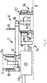
- Figure 1 shows a schematic view of a machine-tool 1 intended for the machining of workpieces by means of a tool fitted in the machine.
- This machine incorporates a first element 2 in the form of a spindle, and a second element 3 in the form of a worktable, which are movable relative to one another in a conventional manner in various directions for machining of a workpiece (not depicted) which is intended to be secured to the worktable and be machined by a tool inserted in the spindle.
- the first element 2 is supported by a spindle head 4 which is itself supported by a frame 5 which also supports the second element 3.
- a test assembly 6 described below and designed according to the invention is clamped between the first element 2 and the second element 3.
- the test assembly 6 incorporates a conventional measuring arm 7 of the "ball bar” type, which has one of its ends linked by an articulation 8 to a bracket 9 intended to be secured in the second element 2 of the machine 1, and has its other end linked via an articulation 10 to a bracket 11 intended to be fixed relative to the second element 3.
- a telescopic element 12 links the two articulations 8 and 10 and is provided internally with measuring equipment (not depicted) for recording changes in the distance between the articulations 8 and 10.
- the measuring arm 7 and its measuring equipment can be connected by an electrical line 13 to suitable external equipment for recording and analysis of measurement results.
- the test assembly 6 also incorporates a power unit 14 which, like the measuring arm 7, is intended to be fixed between the first element 2 and the second element 3.
- a power unit 14 which, like the measuring arm 7, is intended to be fixed between the first element 2 and the second element 3.
- a bracket 15 for fixing to the first element 2 there is not only a bracket 15 for fixing to the first element 2 but also a bracket 16 for fixing to the second element 3.
- the bracket 16 supports a pivotingly mounted arm 18 which has its free end connected to a yoke 19 in which piston rods 20,21 to two working cylinders arranged in a cylinder housing 22 are fastened.
- the cylinder housing 22 is provided with working medium via a line 23 and is fixed to the holder 15 which is intended to be pivotable about the first element 2 via a bearing 24.
- the power unit 14 can be used to apply a force in either direction, parting or drawing together the two brackets 15 and 16, and hence also the first element 2 and the second element 3, when the test assembly 6 is fitted for use according to Figure 1 .
- the measuring arm 7 can at the same time be used to ascertain the magnitude of the resulting displacements between the elements 2 and 3.
- test assembly according to the invention can be used with basically any kind of mechanical structure. It could be part of a machine tool (as described here) as well as of various kinds of robots or coordinate measuring machines.
- Figures 3a and 3b show the results of two test series.
- the results of a first test series are depicted schematically in Figure 3a , in which the machine 1 was programmed to cause the second element 3 to perform a circular movement about the first element 2 during simultaneous application of force between the elements 2 and 3.
- a coordinate system with X-axis and Y-axis has been placed with its centre 24 in the first element 2, and curves a-f show the magnitude of the deflection in various positions resulting from various amounts of force.
- curves b, d and f (provided with arrows) the movement was in a clockwise direction, while that depicted by the other curves a, c and e was in an anticlockwise direction.
- the force applied was 330N on curves a and b, 660N on curves c and d and 825N on curves e and f.
- the feed rate was 1000 mm/min in all cases. As can be seen, the amount of displacement increases with the amount of force applied but differently in different directions of movement.
- Figure 3b shows schematically the results of a test series in somewhat different conditions from the test series in Figure 3a .
- the feed rate was increased to 5000 mm/min.
- the force applied for curves a-d was the same as in Figure 3a but was increased to 990N for curves e and f.
- the amount of deflection increases with the amount of force applied and differs in different directions, but not in the same way as in Figure 3a .
- FIGs in Figures 3a and 3b may be said to constitute the machine's "fingerprint” in various situations and provide, inter alia, information on how its rigidity (or stiffness) varies in different directions at different amounts of load. They also provide a picture of the precision with which the machine can perform a certain type of movement under given conditions.
- FIG. 4 Another type of test result is depicted in Figure 4 , where the change in rectilinearity S, measured in ⁇ m (micrometers), is shown as a function of the magnitude of the force applied F, indicated in N (newtons). It shows that the change is linear.
- bearings 17 and 24 used must have good accuracy, i.e. minimum play, and, at the same time, low friction.
- Sliding or rolling bearings e. g. needle bearings, may be suitable for the purpose but magnetic or hydrostatic bearings are also attractive, although expensive.
- Signal transmission from the measuring arm 7 is here depicted via an electrical line 13 but other versions are of course conceivable, e. g. using some kind of wireless transmission (such as Bluetooth or WiFi transmission) to avoid problems with electrical lines during rotary movements.
- some kind of wireless transmission such as Bluetooth or WiFi transmission
- the first element 2 is fixed while the second element 3 is movable in a plane perpendicular to the plane of the drawing.
- the second element 3 is fixed instead while the first element 2 may be movable.
- a combination of such movements is also possible, depending on what is necessary and desirable in the particular case.
- the power unit 14 described above may within the scope of the invention also take a number of different forms, e. g. it is possible for the arm 18 to take the form of a cylinder housing instead. It is also possible for a single cylinder to be used instead of two, etc.
- brackets 15 and 16 are to make it possible to use the power unit 14 to load the first element 2 and the second element 3, so said brackets have within the scope of the invention to be adapted as appropriate to the particular type of machine.
- Diagrams of the type depicted in Figures 3a, 3b and 4 may be used for calculating a large number of different parameters which characterise the machine's behaviour under load. Precision in circular movement can be read off, but precision in linear movements and various types of composite movement can also be calculated. The amount of force dependency provides a good measure of the machine's quality in that little force dependency indicates good quality and good precision, whereas great force dependency indicates less good quality and inferior precision.
- the measured values arising from testing a certain machine tool according to the invention may be used for imposing corrections to rectify deflection in various load situations in the control programme for the machine concerned.
- the machine's accuracy might thus be substantially improved.
- the economic gains might become significant if relatively inexpensive machines could therefore be used instead of more expensive high-precision machines.
- Said measured values obtained may also be used in digital Simulation of the actual machining process to provide a more realistic picture of that process.
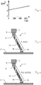
- Figures 5 and 6 each show a schematic representation of a measuring arm 7 of a test assembly, illustrating the working principles of a test assembly of the prior art and of a test assembly according to the invention.
- the measuring arm 7 of the assembly of Figure 5 is fixed to a machine spindle 2 by means of a first bracket 9 and a first articulation 8, and to a machine table 3 by means of a second bracket 11 and a second articulation 10.
- Such an assembly is known from the art and described in US 2002/0189379 A1 .
- Figure 6 illustrates the working principle of an exemplary embodiment of an assembly according to the invention. With the assembly of Figure 6 a dynamic measurement is introduced. The depicted elements of the measuring arm 7 are the same as in Figure 5 .
- the power unit (not shown) of the assembly of Figure 6 is adapted to generate a dynamic, time varying force F(t) between the two articulations 8 and 10 (e. g. by means of a piezo actuator). From the perspective of the machine, this can be regarded as a force vector dependent on the relative position between the two articulations 8 and 10. Accordingly, the measuring arm 7 is adapted to measure the varying length vector dL(F(t)) that in the same way will result in varying stiffness in different directions.
- the applied force F comprises a static component F 0 and a dynamic component F(t).
- the latter is time variant, e. g. sinusoidal or comprising a step function.
- a dynamic force F(t) is applied in combination with a static force F 0 (where the static force can be F 0 ⁇ 0).
- the dynamic component F(t) is designed so that, when observing the system from outside, it behaves as if it would have a negative damping.
- the output comprises the static stiffness (with a constant applied force) as well as the dynamic stiffness (with a time-varying force F(t)) and the damping.
- the static force F 0 and the dynamic force can be generated by the same means or separately, e. g. the static force by means of at least one working cylinder of the power unit (as described with respect to Figures 2a and 2b ) and the dynamic force by means of a piezo actuator.
- the method comprises one or more measurement operations, each of which comprising moving the machine spindle 9 relative to the machine table 3 in a settable pattern of movement and recording the resulting actual movement path.
- this can be a rotational movement with different forces applied by the test assembly.
- the predetermined force F applied during each of the one or more measurement operation comprises a dynamically varying portion F(t), so that the applied force varies dynamically during each of the measurement operations.
- the dynamically varying force can be different for each measurement operation.
- the measuring part for measuring the deflection vector dL(F) and the force-generation part can be designed to be independent components. This means that if the force-generation part is affected by friction or creates deflections in the device, the measuring part will not be affected by these defects and be able to measure the true deflections on the machine.
- test assembly can be used with a rotating spindle, e. g. fixed to the spindle by means of a special adaptor, as the stiffness in the spindle varies with the rotational speed.
- a rotating spindle e. g. fixed to the spindle by means of a special adaptor, as the stiffness in the spindle varies with the rotational speed.
- the forces are applied and the measurement is performed during the rotation of the rotating spindle.
- test assembly can also be used for measuring the stiffness in fixtures that are used for holding the workpiece in its place.
- the assembly can be battery operated.
Landscapes
- Engineering & Computer Science (AREA)
- Mechanical Engineering (AREA)
- Physics & Mathematics (AREA)
- General Physics & Mathematics (AREA)
- Force Measurement Appropriate To Specific Purposes (AREA)
- Machine Tool Sensing Apparatuses (AREA)
Claims (15)
- Procédé permettant de déterminer des paramètres machine d'un dispositif mécanique (1) dans lequel un premier élément (2) et un deuxième élément (3) sont mobiles l'un par rapport à l'autre selon des schémas de mouvement réglables, ledit procédé comprenant• le placement d'un bras mesureur (7) entre le premier et le deuxième élément (2, 3),• le déplacement relatif du premier et du deuxième élément (2, 3) selon une trajectoire prédéterminée souhaitée,• l'application d'une force prédéterminée (F) entre le premier élément (2) et le deuxième élément (3) sensiblement dans le sens longitudinal du bras mesureur (7),• l'enregistrement de la trajectoire résultante réelle au moyen du bras mesureur (7), et ainsi la détermination de la différence entre la trajectoire souhaitée et la trajectoire réelle, et• l'obtention, à partir de la différence ainsi déterminée, de paramètres machine indiquant un état du dispositif mécanique (1),caractérisé en ce que
la force prédéterminée (F) comporte une composante à variation dynamique (F(t)) et une composante statique (F0), la composante à variation dynamique (F(t)) et la composante statique (F0) étant générées par des moyens différents. - Procédé selon la revendication 1,
caractérisé en ce que
la composante à variation dynamique (F(t)) est fonction du temps ou de la position, ladite composante à variation dynamique (F(t)) étant notamment sinusoïdale, ou suivant notamment une fonction analytique ou une fonction échelon. - Procédé selon la revendication 1 ou 2,
caractérisé par
au moins une opération de mesure, notamment une pluralité d'opérations de mesure successives, chacune comprenant le déplacement relatif du premier et du deuxième élément (2, 3) selon un schéma de mouvement réglable et l'enregistrement de la trajectoire résultante réelle, la force prédéterminée (F) appliquée pendant chaque opération de mesure comportant une composante à variation dynamique (F(t)) de sorte que la force appliquée varie dynamiquement pendant chaque opération de mesure, ladite force appliquée qui varie dynamiquement étant notamment différente pour chaque opération de mesure. - Procédé selon l'une quelconque des revendications précédentes,
caractérisé en ce que
la composante à variation dynamique (F(t)) est générée au moins en partie au moyen d'un actionneur piézoélectrique, d'un actionneur hydraulique, d'un actionneur pneumatique, d'un actionneur électromagnétique ou d'un moteur électrique. - Procédé selon l'une quelconque des revendications précédentes,
caractérisé en ce que
la force prédéterminée (F) est définie par
où F est la force prédéterminée, F0 est sa composante statique et (F(t)) est sa composante à variation dynamique. - Procédé selon l'une quelconque des revendications précédentes,
caractérisé en ce que• la force prédéterminée (F) est appliquée alors que le premier et le deuxième élément sont dans diverses positions relatives ; et/ou• l'enregistrement de la trajectoire résultante réelle comprend la détermination dynamique d'une longueur courante ou d'une différence de longueur (dL(F)) du bras mesureur (7) pendant que la force prédéterminée (F) est appliquée. - Procédé selon l'une quelconque des revendications précédentes,
caractérisé en ce que
les paramètres machine comprennent au moins l'un des suivants :• une rigidité, notamment mesurée dans au moins deux directions au moyen d'un vecteur force appliquée et d'un vecteur flexion, et comprenant notamment une valeur de rigidité dynamique ;• un déplacement en fonction d'une direction de mouvement ;• une hystérésis ;• une rectitude ; et/ou• un amortissement. - Procédé selon l'une quelconque des revendications précédentes,
caractérisé en ce que• le dispositif mécanique (1) est une machine-outil, le premier élément (2) étant conçu pour porter un outil d'usinage et le deuxième élément (3) étant conçu pour porter une pièce à usiner, ou• le dispositif mécanique (1) est une machine à mesurer les coordonnées, le premier élément (2) étant conçu pour porter une tête de mesure et le deuxième élément (3) étant conçu pour porter un objet à mesurer,dans lequel procédé, notamment,• le deuxième élément (3) est conçu pour fournir une fixation destinée à maintenir à sa place la pièce à usiner ou l'objet à mesurer, respectivement, notamment au moyen d'un serrage, et• les paramètres machine comprennent une rigidité de la fixation. - Procédé selon l'une quelconque des revendications précédentes,
caractérisé en ce que
le dispositif mécanique (1) est une machine-outil et le procédé comprend une simulation d'usinage d'une opération d'usinage spécifique de la machine-outil, au cours de laquelle• il est effectué des mouvements relatifs du premier élément (2) et du deuxième élément (3) qui sont typiques de l'opération d'usinage, et• la composante à variation dynamique (F(t)) est appliquée d'après les forces typiquement observées pendant l'opération d'usinage. - Assemblage (6) permettant de déterminer des paramètres machine d'un dispositif mécanique (1) dans lequel un premier élément (2) et un deuxième élément (3) sont mobiles l'un par rapport à l'autre, notamment selon le procédé de l'une quelconque des revendications précédentes, ledit assemblage (6) comprenant• un bras mesureur (7) doté, à ses extrémités, de dispositifs de fixation (9, 11) permettant de fixer, au moyen d'articulations (8, 10), respectivement le premier élément (2) et le deuxième élément (3) ; le bras mesureur (7) comprenant un élément télescopique (12) reliant les articulations (8, 10), ainsi que du matériel de mesure servant à enregistrer des variations de distance entre les articulations (8, 10) pour permettre de mesurer des variations de position entre le premier élément (2) et le deuxième élément (3),• une unité motrice (14) conçue pour appliquer au premier élément (2) et au deuxième élément (3) une force prédéterminée sensiblement parallèle au bras mesureur (7),
caractérisé en ce que
l'unité motrice (14) est conçue pour appliquer une force prédéterminée (F) qui comporte au moins une composante à variation dynamique (F(t)) et une composante statique (F0), ladite composante à variation dynamique (F(t)) et ladite composante statique (F0) étant générées par des moyens différents. - Assemblage (6) selon la revendication 10,
caractérisé en ce que
la composante à variation dynamique (F(t)) est fonction du temps ou de la position, ladite composante à variation dynamique (F(t)) étant notamment sinusoïdale, ou suivant notamment une fonction analytique ou une fonction échelon. - Assemblage (6) selon la revendication 10 ou 11,
caractérisé en ce que
l'unité motrice (14) comprend au moins un actionneur piézoélectrique, un actionneur hydraulique, un actionneur pneumatique, un actionneur électromagnétique ou un moteur électrique conçu pour générer la composante à variation dynamique (F(t)). - Assemblage (6) selon l'une quelconque des revendications 10 à 12,
caractérisé en ce que
l'unité motrice (14)• comprend au moins un vérin actif conçu pour générer une composante statique (F0) de la force prédéterminée (F) ; et/ou• est dotée d'une première monture (15) destinée à être fixée au premier élément (2) et d'une deuxième monture (16) destinée à être fixée au deuxième élément (3), la première et la deuxième monture (15, 16) étant chacune dotées d'un roulement (24, 17) qui permet la rotation de l'unité motrice (14), la deuxième monture (16) étant notamment dotée de dispositifs permettant d'en fixer une extrémité au bras mesureur (7). - Assemblage (6) selon l'une quelconque des revendications 10 à 13,
caractérisé en ce que
le premier élément (2) est une broche rotative, ledit assemblage (6), notamment,• comprenant un adaptateur destiné à fixer l'assemblage (6) à la broche, et• étant conçu pour mesurer une rigidité de la broche, la rigidité variant avec la vitesse de rotation de la broche. - Assemblage (6) selon l'une quelconque des revendications 10 à 14,
caractérisé en ce que
celui-ci est conçu pour fonctionner sans fil et au moyen d'une batterie, ledit assemblage (6) comprenant notamment une batterie à accumulateur installée de manière fixe ou des moyens permettant de recevoir une batterie amovible.
Priority Applications (3)
| Application Number | Priority Date | Filing Date | Title |
|---|---|---|---|
| EP15155654.5A EP3059548B1 (fr) | 2015-02-18 | 2015-02-18 | Procédé et ensemble de test permettant de déterminer des paramètres de machine |
| CN201610080977.8A CN105881099B (zh) | 2015-02-18 | 2016-02-04 | 用于确定机器参数的方法及测试组件 |
| US15/045,905 US10675725B2 (en) | 2015-02-18 | 2016-02-17 | Method and test assembly for determining machine parameters |
Applications Claiming Priority (1)
| Application Number | Priority Date | Filing Date | Title |
|---|---|---|---|
| EP15155654.5A EP3059548B1 (fr) | 2015-02-18 | 2015-02-18 | Procédé et ensemble de test permettant de déterminer des paramètres de machine |
Publications (2)
| Publication Number | Publication Date |
|---|---|
| EP3059548A1 EP3059548A1 (fr) | 2016-08-24 |
| EP3059548B1 true EP3059548B1 (fr) | 2017-11-22 |
Family
ID=52574046
Family Applications (1)
| Application Number | Title | Priority Date | Filing Date |
|---|---|---|---|
| EP15155654.5A Active EP3059548B1 (fr) | 2015-02-18 | 2015-02-18 | Procédé et ensemble de test permettant de déterminer des paramètres de machine |
Country Status (3)
| Country | Link |
|---|---|
| US (1) | US10675725B2 (fr) |
| EP (1) | EP3059548B1 (fr) |
| CN (1) | CN105881099B (fr) |
Families Citing this family (5)
| Publication number | Priority date | Publication date | Assignee | Title |
|---|---|---|---|---|
| TWI850251B (zh) | 2018-09-03 | 2024-08-01 | 義大利商Hsd股份公司 | 工具機、用於工具機的操作裝置、以及收集工具機的操作資料的系統及方法 |
| ES2969876T3 (es) * | 2019-01-18 | 2024-05-23 | Szipka Karoly | Sistema de medición, y un procedimiento en relación con el sistema de medición |
| CN112496859B (zh) * | 2020-12-07 | 2024-09-24 | 中国工程物理研究院机械制造工艺研究所 | 一种液体静压导轨综合性能的动态测量装置及方法 |
| JP7650597B2 (ja) * | 2021-06-15 | 2025-03-25 | 株式会社ディスコ | 測定治具、動作精度測定システム、及び動作精度測定方法 |
| TWI774504B (zh) * | 2021-08-06 | 2022-08-11 | 國立陽明交通大學 | 工具機循圓量測調機方法 |
Family Cites Families (12)
| Publication number | Priority date | Publication date | Assignee | Title |
|---|---|---|---|---|
| KR910005508B1 (ko) * | 1989-05-23 | 1991-07-31 | 박준호 | 컴퓨터 원용 키이니매틱 트랜듀서 링크 시스템 및 그 시스템을 사용한 nc 공작기계 정밀도의 측정 및 해석방법 |
| US5440183A (en) * | 1991-07-12 | 1995-08-08 | Denne Developments, Ltd. | Electromagnetic apparatus for producing linear motion |
| GB9401692D0 (en) * | 1994-01-28 | 1994-03-23 | Renishaw Plc | Performing measurement or calibration on positioning machines |
| US5671541A (en) * | 1995-09-01 | 1997-09-30 | Brown & Sharpe Manufacturing Company | Accuracy verification devices for coordinate measuring machines |
| US6468082B1 (en) * | 1997-09-17 | 2002-10-22 | Advanced Motion Technologies, Llc | Motion-imparting apparatus |
| SE514469C2 (sv) | 1999-12-29 | 2001-02-26 | Scania Cv Ab | Förfarande och anordning vid maskinprovning |
| DE10131408C2 (de) * | 2001-06-28 | 2003-10-23 | Daimler Chrysler Ag | Diagnosesystem für Dreh-Schwenkköpfe |
| WO2004034164A1 (fr) * | 2002-10-11 | 2004-04-22 | Fidia S.P.A. | Systeme te procede de mesure, de compensation et de test de tetes et/ou de tables d'outil de machine a commande numerique |
| US7245982B2 (en) | 2002-10-11 | 2007-07-17 | Fidia S.P.A. | System and process for measuring, compensating and testing numerically controlled machine tool heads and/or tables |
| CN101813550A (zh) * | 2009-11-05 | 2010-08-25 | 吉林大学 | 一体式铁路车辆转向架参数动态测试台 |
| CN103158035A (zh) * | 2011-12-16 | 2013-06-19 | 贵州大学 | 轴类零件的静态挤压力测试装置 |
| CN103286633B (zh) * | 2013-06-14 | 2015-10-14 | 沈阳飞机工业(集团)有限公司 | 五坐标数控机床摆角快速测量系统及误差补偿方法 |
-
2015
- 2015-02-18 EP EP15155654.5A patent/EP3059548B1/fr active Active
-
2016
- 2016-02-04 CN CN201610080977.8A patent/CN105881099B/zh active Active
- 2016-02-17 US US15/045,905 patent/US10675725B2/en active Active
Non-Patent Citations (1)
| Title |
|---|
| None * |
Also Published As
| Publication number | Publication date |
|---|---|
| US20160236313A1 (en) | 2016-08-18 |
| CN105881099B (zh) | 2018-10-30 |
| EP3059548A1 (fr) | 2016-08-24 |
| US10675725B2 (en) | 2020-06-09 |
| CN105881099A (zh) | 2016-08-24 |
Similar Documents
| Publication | Publication Date | Title |
|---|---|---|
| EP3059548B1 (fr) | Procédé et ensemble de test permettant de déterminer des paramètres de machine | |
| EP2156921B1 (fr) | Dispositif de réduction d'oscillations d'une broche d'outil | |
| Archenti et al. | Accuracy analysis of machine tools using Elastically Linked Systems | |
| CN104204717B (zh) | 确定用于监测流体轴承和具有至少一个流体轴承的机器的校正值的方法 | |
| JP2021088024A (ja) | 数値制御装置、及び制御方法 | |
| CN109807685B (zh) | 工具寿命判定装置 | |
| US11400597B2 (en) | Methods for the correction of axis motions | |
| CN1824461A (zh) | 测量数控机床的方法 | |
| KR20180116361A (ko) | 공작기계의 열변위 보정 파라메터 자동 변환 장치 및 변환 방법 | |
| US12485512B2 (en) | Apparatus for active contact force control in machining and handling operations | |
| CN115931223A (zh) | 一种大型异形结构件的高精度质心测量的工艺方法 | |
| EP1247064B1 (fr) | Procede et dispositif permettant de tester une machine-outil | |
| DE102020212982A1 (de) | Verfahren zur Verringerung von Messfehlern eines Koordinatenmessgeräts und Koordinatenmessgerät | |
| KR101823052B1 (ko) | 자동 선반 가공 후 자동 보정을 위한 가공물 측정 방법 | |
| Røsjordet et al. | Methods for experimentally determining stiffness of a multi-axis machining centre | |
| Brecher et al. | Static Behavior of Machine Tools | |
| Laspas | Closed force loop evaluation of machining systems | |
| KR20250131718A (ko) | 공작 기계의 기하 오차 동정 방법 | |
| Magoulidou et al. | Comparative study of the static andquasi-static compliance measurementprocedures on machine tools | |
| Tonoiu et al. | Equipment and procedure for experimental determination of static rigidity of engine lathes | |
| Michalski et al. | The impact of support points during the measurement of machine tool bodies on Coordinate Measuring Machines | |
| Kuric et al. | Quality of CNC machine tools and monitoring of their accuracy | |
| Shen et al. | Analysis on volumetric positioning error development due to thermal effect based on the diagonal measurement | |
| PL243073B1 (pl) | Urządzenie do doświadczalnego wyznaczania sztywności obrabiarek skrawających | |
| Hong et al. | Influence of component errors of rotary axes on a machining test of cone frustum by five-axis machine tools |
Legal Events
| Date | Code | Title | Description |
|---|---|---|---|
| PUAI | Public reference made under article 153(3) epc to a published international application that has entered the european phase |
Free format text: ORIGINAL CODE: 0009012 |
|
| AK | Designated contracting states |
Kind code of ref document: A1 Designated state(s): AL AT BE BG CH CY CZ DE DK EE ES FI FR GB GR HR HU IE IS IT LI LT LU LV MC MK MT NL NO PL PT RO RS SE SI SK SM TR |
|
| AX | Request for extension of the european patent |
Extension state: BA ME |
|
| 17P | Request for examination filed |
Effective date: 20170216 |
|
| RBV | Designated contracting states (corrected) |
Designated state(s): AL AT BE BG CH CY CZ DE DK EE ES FI FR GB GR HR HU IE IS IT LI LT LU LV MC MK MT NL NO PL PT RO RS SE SI SK SM TR |
|
| GRAP | Despatch of communication of intention to grant a patent |
Free format text: ORIGINAL CODE: EPIDOSNIGR1 |
|
| RIC1 | Information provided on ipc code assigned before grant |
Ipc: B23Q 17/00 20060101ALI20170703BHEP Ipc: B23Q 17/22 20060101ALI20170703BHEP Ipc: G01B 21/04 20060101AFI20170703BHEP Ipc: G01B 7/14 20060101ALI20170703BHEP |
|
| INTG | Intention to grant announced |
Effective date: 20170718 |
|
| RIN1 | Information on inventor provided before grant (corrected) |
Inventor name: ARCHENTI, ANDREAS Inventor name: PETTERSSON, BO |
|
| GRAS | Grant fee paid |
Free format text: ORIGINAL CODE: EPIDOSNIGR3 |
|
| GRAA | (expected) grant |
Free format text: ORIGINAL CODE: 0009210 |
|
| AK | Designated contracting states |
Kind code of ref document: B1 Designated state(s): AL AT BE BG CH CY CZ DE DK EE ES FI FR GB GR HR HU IE IS IT LI LT LU LV MC MK MT NL NO PL PT RO RS SE SI SK SM TR |
|
| REG | Reference to a national code |
Ref country code: GB Ref legal event code: FG4D |
|
| REG | Reference to a national code |
Ref country code: CH Ref legal event code: EP |
|
| REG | Reference to a national code |
Ref country code: IE Ref legal event code: FG4D |
|
| REG | Reference to a national code |
Ref country code: AT Ref legal event code: REF Ref document number: 948825 Country of ref document: AT Kind code of ref document: T Effective date: 20171215 |
|
| REG | Reference to a national code |
Ref country code: DE Ref legal event code: R096 Ref document number: 602015006091 Country of ref document: DE |
|
| REG | Reference to a national code |
Ref country code: CH Ref legal event code: NV Representative=s name: KAMINSKI HARMANN PATENTANWAELTE AG, LI |
|
| REG | Reference to a national code |
Ref country code: NL Ref legal event code: FP |
|
| REG | Reference to a national code |
Ref country code: FR Ref legal event code: PLFP Year of fee payment: 4 |
|
| REG | Reference to a national code |
Ref country code: SE Ref legal event code: TRGR |
|
| REG | Reference to a national code |
Ref country code: LT Ref legal event code: MG4D |
|
| REG | Reference to a national code |
Ref country code: AT Ref legal event code: MK05 Ref document number: 948825 Country of ref document: AT Kind code of ref document: T Effective date: 20171122 |
|
| PG25 | Lapsed in a contracting state [announced via postgrant information from national office to epo] |
Ref country code: NO Free format text: LAPSE BECAUSE OF FAILURE TO SUBMIT A TRANSLATION OF THE DESCRIPTION OR TO PAY THE FEE WITHIN THE PRESCRIBED TIME-LIMIT Effective date: 20180222 Ref country code: ES Free format text: LAPSE BECAUSE OF FAILURE TO SUBMIT A TRANSLATION OF THE DESCRIPTION OR TO PAY THE FEE WITHIN THE PRESCRIBED TIME-LIMIT Effective date: 20171122 Ref country code: LT Free format text: LAPSE BECAUSE OF FAILURE TO SUBMIT A TRANSLATION OF THE DESCRIPTION OR TO PAY THE FEE WITHIN THE PRESCRIBED TIME-LIMIT Effective date: 20171122 Ref country code: FI Free format text: LAPSE BECAUSE OF FAILURE TO SUBMIT A TRANSLATION OF THE DESCRIPTION OR TO PAY THE FEE WITHIN THE PRESCRIBED TIME-LIMIT Effective date: 20171122 |
|
| PG25 | Lapsed in a contracting state [announced via postgrant information from national office to epo] |
Ref country code: RS Free format text: LAPSE BECAUSE OF FAILURE TO SUBMIT A TRANSLATION OF THE DESCRIPTION OR TO PAY THE FEE WITHIN THE PRESCRIBED TIME-LIMIT Effective date: 20171122 Ref country code: AT Free format text: LAPSE BECAUSE OF FAILURE TO SUBMIT A TRANSLATION OF THE DESCRIPTION OR TO PAY THE FEE WITHIN THE PRESCRIBED TIME-LIMIT Effective date: 20171122 Ref country code: HR Free format text: LAPSE BECAUSE OF FAILURE TO SUBMIT A TRANSLATION OF THE DESCRIPTION OR TO PAY THE FEE WITHIN THE PRESCRIBED TIME-LIMIT Effective date: 20171122 Ref country code: BG Free format text: LAPSE BECAUSE OF FAILURE TO SUBMIT A TRANSLATION OF THE DESCRIPTION OR TO PAY THE FEE WITHIN THE PRESCRIBED TIME-LIMIT Effective date: 20180222 Ref country code: LV Free format text: LAPSE BECAUSE OF FAILURE TO SUBMIT A TRANSLATION OF THE DESCRIPTION OR TO PAY THE FEE WITHIN THE PRESCRIBED TIME-LIMIT Effective date: 20171122 Ref country code: GR Free format text: LAPSE BECAUSE OF FAILURE TO SUBMIT A TRANSLATION OF THE DESCRIPTION OR TO PAY THE FEE WITHIN THE PRESCRIBED TIME-LIMIT Effective date: 20180223 |
|
| PG25 | Lapsed in a contracting state [announced via postgrant information from national office to epo] |
Ref country code: SK Free format text: LAPSE BECAUSE OF FAILURE TO SUBMIT A TRANSLATION OF THE DESCRIPTION OR TO PAY THE FEE WITHIN THE PRESCRIBED TIME-LIMIT Effective date: 20171122 Ref country code: CZ Free format text: LAPSE BECAUSE OF FAILURE TO SUBMIT A TRANSLATION OF THE DESCRIPTION OR TO PAY THE FEE WITHIN THE PRESCRIBED TIME-LIMIT Effective date: 20171122 Ref country code: DK Free format text: LAPSE BECAUSE OF FAILURE TO SUBMIT A TRANSLATION OF THE DESCRIPTION OR TO PAY THE FEE WITHIN THE PRESCRIBED TIME-LIMIT Effective date: 20171122 Ref country code: CY Free format text: LAPSE BECAUSE OF FAILURE TO SUBMIT A TRANSLATION OF THE DESCRIPTION OR TO PAY THE FEE WITHIN THE PRESCRIBED TIME-LIMIT Effective date: 20171122 Ref country code: EE Free format text: LAPSE BECAUSE OF FAILURE TO SUBMIT A TRANSLATION OF THE DESCRIPTION OR TO PAY THE FEE WITHIN THE PRESCRIBED TIME-LIMIT Effective date: 20171122 |
|
| REG | Reference to a national code |
Ref country code: DE Ref legal event code: R097 Ref document number: 602015006091 Country of ref document: DE |
|
| PG25 | Lapsed in a contracting state [announced via postgrant information from national office to epo] |
Ref country code: PL Free format text: LAPSE BECAUSE OF FAILURE TO SUBMIT A TRANSLATION OF THE DESCRIPTION OR TO PAY THE FEE WITHIN THE PRESCRIBED TIME-LIMIT Effective date: 20171122 Ref country code: RO Free format text: LAPSE BECAUSE OF FAILURE TO SUBMIT A TRANSLATION OF THE DESCRIPTION OR TO PAY THE FEE WITHIN THE PRESCRIBED TIME-LIMIT Effective date: 20171122 Ref country code: SM Free format text: LAPSE BECAUSE OF FAILURE TO SUBMIT A TRANSLATION OF THE DESCRIPTION OR TO PAY THE FEE WITHIN THE PRESCRIBED TIME-LIMIT Effective date: 20171122 Ref country code: IT Free format text: LAPSE BECAUSE OF FAILURE TO SUBMIT A TRANSLATION OF THE DESCRIPTION OR TO PAY THE FEE WITHIN THE PRESCRIBED TIME-LIMIT Effective date: 20171122 |
|
| PG25 | Lapsed in a contracting state [announced via postgrant information from national office to epo] |
Ref country code: MC Free format text: LAPSE BECAUSE OF FAILURE TO SUBMIT A TRANSLATION OF THE DESCRIPTION OR TO PAY THE FEE WITHIN THE PRESCRIBED TIME-LIMIT Effective date: 20171122 |
|
| PLBE | No opposition filed within time limit |
Free format text: ORIGINAL CODE: 0009261 |
|
| STAA | Information on the status of an ep patent application or granted ep patent |
Free format text: STATUS: NO OPPOSITION FILED WITHIN TIME LIMIT |
|
| 26N | No opposition filed |
Effective date: 20180823 |
|
| REG | Reference to a national code |
Ref country code: IE Ref legal event code: MM4A |
|
| REG | Reference to a national code |
Ref country code: BE Ref legal event code: MM Effective date: 20180228 |
|
| PG25 | Lapsed in a contracting state [announced via postgrant information from national office to epo] |
Ref country code: SI Free format text: LAPSE BECAUSE OF FAILURE TO SUBMIT A TRANSLATION OF THE DESCRIPTION OR TO PAY THE FEE WITHIN THE PRESCRIBED TIME-LIMIT Effective date: 20171122 Ref country code: LU Free format text: LAPSE BECAUSE OF NON-PAYMENT OF DUE FEES Effective date: 20180218 |
|
| PG25 | Lapsed in a contracting state [announced via postgrant information from national office to epo] |
Ref country code: IE Free format text: LAPSE BECAUSE OF NON-PAYMENT OF DUE FEES Effective date: 20180218 |
|
| PG25 | Lapsed in a contracting state [announced via postgrant information from national office to epo] |
Ref country code: BE Free format text: LAPSE BECAUSE OF NON-PAYMENT OF DUE FEES Effective date: 20180228 |
|
| PG25 | Lapsed in a contracting state [announced via postgrant information from national office to epo] |
Ref country code: MT Free format text: LAPSE BECAUSE OF NON-PAYMENT OF DUE FEES Effective date: 20180218 |
|
| PG25 | Lapsed in a contracting state [announced via postgrant information from national office to epo] |
Ref country code: TR Free format text: LAPSE BECAUSE OF FAILURE TO SUBMIT A TRANSLATION OF THE DESCRIPTION OR TO PAY THE FEE WITHIN THE PRESCRIBED TIME-LIMIT Effective date: 20171122 |
|
| PGFP | Annual fee paid to national office [announced via postgrant information from national office to epo] |
Ref country code: NL Payment date: 20200219 Year of fee payment: 6 Ref country code: SE Payment date: 20200220 Year of fee payment: 6 |
|
| PG25 | Lapsed in a contracting state [announced via postgrant information from national office to epo] |
Ref country code: PT Free format text: LAPSE BECAUSE OF FAILURE TO SUBMIT A TRANSLATION OF THE DESCRIPTION OR TO PAY THE FEE WITHIN THE PRESCRIBED TIME-LIMIT Effective date: 20171122 |
|
| PGFP | Annual fee paid to national office [announced via postgrant information from national office to epo] |
Ref country code: CH Payment date: 20200219 Year of fee payment: 6 |
|
| PG25 | Lapsed in a contracting state [announced via postgrant information from national office to epo] |
Ref country code: MK Free format text: LAPSE BECAUSE OF NON-PAYMENT OF DUE FEES Effective date: 20171122 Ref country code: HU Free format text: LAPSE BECAUSE OF FAILURE TO SUBMIT A TRANSLATION OF THE DESCRIPTION OR TO PAY THE FEE WITHIN THE PRESCRIBED TIME-LIMIT; INVALID AB INITIO Effective date: 20150218 |
|
| PG25 | Lapsed in a contracting state [announced via postgrant information from national office to epo] |
Ref country code: IS Free format text: LAPSE BECAUSE OF FAILURE TO SUBMIT A TRANSLATION OF THE DESCRIPTION OR TO PAY THE FEE WITHIN THE PRESCRIBED TIME-LIMIT Effective date: 20180322 Ref country code: AL Free format text: LAPSE BECAUSE OF FAILURE TO SUBMIT A TRANSLATION OF THE DESCRIPTION OR TO PAY THE FEE WITHIN THE PRESCRIBED TIME-LIMIT Effective date: 20171122 |
|
| REG | Reference to a national code |
Ref country code: SE Ref legal event code: EUG |
|
| PG25 | Lapsed in a contracting state [announced via postgrant information from national office to epo] |
Ref country code: LI Free format text: LAPSE BECAUSE OF NON-PAYMENT OF DUE FEES Effective date: 20210228 Ref country code: CH Free format text: LAPSE BECAUSE OF NON-PAYMENT OF DUE FEES Effective date: 20210228 |
|
| PG25 | Lapsed in a contracting state [announced via postgrant information from national office to epo] |
Ref country code: SE Free format text: LAPSE BECAUSE OF NON-PAYMENT OF DUE FEES Effective date: 20210219 |
|
| REG | Reference to a national code |
Ref country code: NL Ref legal event code: MM Effective date: 20210301 |
|
| PG25 | Lapsed in a contracting state [announced via postgrant information from national office to epo] |
Ref country code: NL Free format text: LAPSE BECAUSE OF NON-PAYMENT OF DUE FEES Effective date: 20210301 |
|
| REG | Reference to a national code |
Ref country code: DE Ref legal event code: R081 Ref document number: 602015006091 Country of ref document: DE Owner name: HEXAGON INNOVATION HUB GMBH, CH Free format text: FORMER OWNER: HEXAGON TECHNOLOGY CENTER GMBH, HEERBRUGG, CH |
|
| REG | Reference to a national code |
Ref country code: GB Ref legal event code: 732E Free format text: REGISTERED BETWEEN 20260305 AND 20260311 |
|
| PGFP | Annual fee paid to national office [announced via postgrant information from national office to epo] |
Ref country code: GB Payment date: 20260219 Year of fee payment: 12 |
|
| PGFP | Annual fee paid to national office [announced via postgrant information from national office to epo] |
Ref country code: DE Payment date: 20260218 Year of fee payment: 12 |
|
| PGFP | Annual fee paid to national office [announced via postgrant information from national office to epo] |
Ref country code: FR Payment date: 20260218 Year of fee payment: 12 |