EP3059559A1 - Système de radar FMCW - Google Patents
Système de radar FMCW Download PDFInfo
- Publication number
- EP3059559A1 EP3059559A1 EP15156085.1A EP15156085A EP3059559A1 EP 3059559 A1 EP3059559 A1 EP 3059559A1 EP 15156085 A EP15156085 A EP 15156085A EP 3059559 A1 EP3059559 A1 EP 3059559A1
- Authority
- EP
- European Patent Office
- Prior art keywords
- signal
- radar system
- fmcw radar
- processing unit
- digital processing
- Prior art date
- Legal status (The legal status is an assumption and is not a legal conclusion. Google has not performed a legal analysis and makes no representation as to the accuracy of the status listed.)
- Withdrawn
Links
Images
Classifications
-
- G—PHYSICS
- G01—MEASURING; TESTING
- G01S—RADIO DIRECTION-FINDING; RADIO NAVIGATION; DETERMINING DISTANCE OR VELOCITY BY USE OF RADIO WAVES; LOCATING OR PRESENCE-DETECTING BY USE OF THE REFLECTION OR RERADIATION OF RADIO WAVES; ANALOGOUS ARRANGEMENTS USING OTHER WAVES
- G01S13/00—Systems using the reflection or reradiation of radio waves, e.g. radar systems; Analogous systems using reflection or reradiation of waves whose nature or wavelength is irrelevant or unspecified
- G01S13/02—Systems using reflection of radio waves, e.g. primary radar systems; Analogous systems
- G01S13/06—Systems determining position data of a target
- G01S13/08—Systems for measuring distance only
- G01S13/32—Systems for measuring distance only using transmission of continuous waves, whether amplitude-, frequency-, or phase-modulated, or unmodulated
- G01S13/34—Systems for measuring distance only using transmission of continuous waves, whether amplitude-, frequency-, or phase-modulated, or unmodulated using transmission of continuous, frequency-modulated waves while heterodyning the received signal, or a signal derived therefrom, with a locally-generated signal related to the contemporaneously transmitted signal
-
- G—PHYSICS
- G01—MEASURING; TESTING
- G01F—MEASURING VOLUME, VOLUME FLOW, MASS FLOW OR LIQUID LEVEL; METERING BY VOLUME
- G01F23/00—Indicating or measuring liquid level or level of fluent solid material, e.g. indicating in terms of volume or indicating by means of an alarm
- G01F23/22—Indicating or measuring liquid level or level of fluent solid material, e.g. indicating in terms of volume or indicating by means of an alarm by measuring physical variables, other than linear dimensions, pressure or weight, dependent on the level to be measured, e.g. by difference of heat transfer of steam or water
- G01F23/28—Indicating or measuring liquid level or level of fluent solid material, e.g. indicating in terms of volume or indicating by means of an alarm by measuring physical variables, other than linear dimensions, pressure or weight, dependent on the level to be measured, e.g. by difference of heat transfer of steam or water by measuring the variations of parameters of electromagnetic or acoustic waves applied directly to the liquid or fluent solid material
- G01F23/284—Electromagnetic waves
-
- G—PHYSICS
- G01—MEASURING; TESTING
- G01S—RADIO DIRECTION-FINDING; RADIO NAVIGATION; DETERMINING DISTANCE OR VELOCITY BY USE OF RADIO WAVES; LOCATING OR PRESENCE-DETECTING BY USE OF THE REFLECTION OR RERADIATION OF RADIO WAVES; ANALOGOUS ARRANGEMENTS USING OTHER WAVES
- G01S13/00—Systems using the reflection or reradiation of radio waves, e.g. radar systems; Analogous systems using reflection or reradiation of waves whose nature or wavelength is irrelevant or unspecified
- G01S13/02—Systems using reflection of radio waves, e.g. primary radar systems; Analogous systems
- G01S13/06—Systems determining position data of a target
- G01S13/08—Systems for measuring distance only
- G01S13/32—Systems for measuring distance only using transmission of continuous waves, whether amplitude-, frequency-, or phase-modulated, or unmodulated
- G01S13/34—Systems for measuring distance only using transmission of continuous waves, whether amplitude-, frequency-, or phase-modulated, or unmodulated using transmission of continuous, frequency-modulated waves while heterodyning the received signal, or a signal derived therefrom, with a locally-generated signal related to the contemporaneously transmitted signal
- G01S13/343—Systems for measuring distance only using transmission of continuous waves, whether amplitude-, frequency-, or phase-modulated, or unmodulated using transmission of continuous, frequency-modulated waves while heterodyning the received signal, or a signal derived therefrom, with a locally-generated signal related to the contemporaneously transmitted signal using sawtooth modulation
-
- G—PHYSICS
- G01—MEASURING; TESTING
- G01S—RADIO DIRECTION-FINDING; RADIO NAVIGATION; DETERMINING DISTANCE OR VELOCITY BY USE OF RADIO WAVES; LOCATING OR PRESENCE-DETECTING BY USE OF THE REFLECTION OR RERADIATION OF RADIO WAVES; ANALOGOUS ARRANGEMENTS USING OTHER WAVES
- G01S13/00—Systems using the reflection or reradiation of radio waves, e.g. radar systems; Analogous systems using reflection or reradiation of waves whose nature or wavelength is irrelevant or unspecified
- G01S13/02—Systems using reflection of radio waves, e.g. primary radar systems; Analogous systems
- G01S13/06—Systems determining position data of a target
- G01S13/08—Systems for measuring distance only
- G01S13/32—Systems for measuring distance only using transmission of continuous waves, whether amplitude-, frequency-, or phase-modulated, or unmodulated
- G01S13/34—Systems for measuring distance only using transmission of continuous waves, whether amplitude-, frequency-, or phase-modulated, or unmodulated using transmission of continuous, frequency-modulated waves while heterodyning the received signal, or a signal derived therefrom, with a locally-generated signal related to the contemporaneously transmitted signal
- G01S13/345—Systems for measuring distance only using transmission of continuous waves, whether amplitude-, frequency-, or phase-modulated, or unmodulated using transmission of continuous, frequency-modulated waves while heterodyning the received signal, or a signal derived therefrom, with a locally-generated signal related to the contemporaneously transmitted signal using triangular modulation
-
- G—PHYSICS
- G01—MEASURING; TESTING
- G01S—RADIO DIRECTION-FINDING; RADIO NAVIGATION; DETERMINING DISTANCE OR VELOCITY BY USE OF RADIO WAVES; LOCATING OR PRESENCE-DETECTING BY USE OF THE REFLECTION OR RERADIATION OF RADIO WAVES; ANALOGOUS ARRANGEMENTS USING OTHER WAVES
- G01S7/00—Details of systems according to groups G01S13/00, G01S15/00, G01S17/00
- G01S7/02—Details of systems according to groups G01S13/00, G01S15/00, G01S17/00 of systems according to group G01S13/00
- G01S7/40—Means for monitoring or calibrating
- G01S7/4052—Means for monitoring or calibrating by simulation of echoes
-
- G—PHYSICS
- G01—MEASURING; TESTING
- G01S—RADIO DIRECTION-FINDING; RADIO NAVIGATION; DETERMINING DISTANCE OR VELOCITY BY USE OF RADIO WAVES; LOCATING OR PRESENCE-DETECTING BY USE OF THE REFLECTION OR RERADIATION OF RADIO WAVES; ANALOGOUS ARRANGEMENTS USING OTHER WAVES
- G01S7/00—Details of systems according to groups G01S13/00, G01S15/00, G01S17/00
- G01S7/02—Details of systems according to groups G01S13/00, G01S15/00, G01S17/00 of systems according to group G01S13/00
- G01S7/40—Means for monitoring or calibrating
- G01S7/4052—Means for monitoring or calibrating by simulation of echoes
- G01S7/4056—Means for monitoring or calibrating by simulation of echoes specially adapted to FMCW
-
- G—PHYSICS
- G01—MEASURING; TESTING
- G01S—RADIO DIRECTION-FINDING; RADIO NAVIGATION; DETERMINING DISTANCE OR VELOCITY BY USE OF RADIO WAVES; LOCATING OR PRESENCE-DETECTING BY USE OF THE REFLECTION OR RERADIATION OF RADIO WAVES; ANALOGOUS ARRANGEMENTS USING OTHER WAVES
- G01S13/00—Systems using the reflection or reradiation of radio waves, e.g. radar systems; Analogous systems using reflection or reradiation of waves whose nature or wavelength is irrelevant or unspecified
- G01S13/88—Radar or analogous systems specially adapted for specific applications
- G01S13/93—Radar or analogous systems specially adapted for specific applications for anti-collision purposes
- G01S13/931—Radar or analogous systems specially adapted for specific applications for anti-collision purposes of land vehicles
-
- G—PHYSICS
- G01—MEASURING; TESTING
- G01S—RADIO DIRECTION-FINDING; RADIO NAVIGATION; DETERMINING DISTANCE OR VELOCITY BY USE OF RADIO WAVES; LOCATING OR PRESENCE-DETECTING BY USE OF THE REFLECTION OR RERADIATION OF RADIO WAVES; ANALOGOUS ARRANGEMENTS USING OTHER WAVES
- G01S3/00—Direction-finders for determining the direction from which infrasonic, sonic, ultrasonic or electromagnetic waves, or particle emission, not having a directional significance, are being received
- G01S3/02—Direction-finders for determining the direction from which infrasonic, sonic, ultrasonic or electromagnetic waves, or particle emission, not having a directional significance, are being received using radio waves
- G01S3/14—Systems for determining direction or deviation from predetermined direction
- G01S3/46—Systems for determining direction or deviation from predetermined direction using antennas spaced apart and measuring phase or time difference between signals therefrom, i.e. path-difference systems
- G01S3/48—Systems for determining direction or deviation from predetermined direction using antennas spaced apart and measuring phase or time difference between signals therefrom, i.e. path-difference systems the waves arriving at the antennas being continuous or intermittent and the phase difference of signals derived therefrom being measured
-
- G—PHYSICS
- G01—MEASURING; TESTING
- G01S—RADIO DIRECTION-FINDING; RADIO NAVIGATION; DETERMINING DISTANCE OR VELOCITY BY USE OF RADIO WAVES; LOCATING OR PRESENCE-DETECTING BY USE OF THE REFLECTION OR RERADIATION OF RADIO WAVES; ANALOGOUS ARRANGEMENTS USING OTHER WAVES
- G01S7/00—Details of systems according to groups G01S13/00, G01S15/00, G01S17/00
- G01S7/02—Details of systems according to groups G01S13/00, G01S15/00, G01S17/00 of systems according to group G01S13/00
- G01S7/40—Means for monitoring or calibrating
- G01S7/4052—Means for monitoring or calibrating by simulation of echoes
- G01S7/406—Means for monitoring or calibrating by simulation of echoes using internally generated reference signals, e.g. via delay line, via RF or IF signal injection or via integrated reference reflector or transponder
-
- G—PHYSICS
- G01—MEASURING; TESTING
- G01S—RADIO DIRECTION-FINDING; RADIO NAVIGATION; DETERMINING DISTANCE OR VELOCITY BY USE OF RADIO WAVES; LOCATING OR PRESENCE-DETECTING BY USE OF THE REFLECTION OR RERADIATION OF RADIO WAVES; ANALOGOUS ARRANGEMENTS USING OTHER WAVES
- G01S7/00—Details of systems according to groups G01S13/00, G01S15/00, G01S17/00
- G01S7/02—Details of systems according to groups G01S13/00, G01S15/00, G01S17/00 of systems according to group G01S13/00
- G01S7/40—Means for monitoring or calibrating
- G01S7/4052—Means for monitoring or calibrating by simulation of echoes
- G01S7/406—Means for monitoring or calibrating by simulation of echoes using internally generated reference signals, e.g. via delay line, via RF or IF signal injection or via integrated reference reflector or transponder
- G01S7/4073—Means for monitoring or calibrating by simulation of echoes using internally generated reference signals, e.g. via delay line, via RF or IF signal injection or via integrated reference reflector or transponder involving an IF signal injection
Definitions
- the invention relates to an FMCW radar system for level or distance measurement, comprising:
- Such an FMCW radar system is known from WO 2013/164456 A1 .
- the analog filter unit has a high-pass characteristic in order to reduce the dynamic range of the beat signal.
- the filter function can affect the curve of the beat signal and thus the accuracy of the measurement.
- the signal generator generates a reference signal which is used to correct errors of the filtered and digitized beat signal, which errors are caused by the analog filter unit.
- the reference signal is swept from 0 Hz to the highest occurring beat frequency and the filter function (with attenuation and phase response) is recorded by the digital processing unit. From this data, an inverse filter function is calculated and used to correct the digitized sampled values of the beat signal obtained during the level or distance measurement.
- FMEDA Failure Modes, Effects and Diagnostic Analysis
- the beat signal is a complex waveform consisting of several frequency components which depend on the target conditions.
- the filter unit has the double function of improving the dynamic range of the beat signal by increasing the gain as the measurement range increases and anti-aliasing to remove high frequency components from the beat signal before digitization and processing. All this results in a complex filter design which negatively affects the probability of a failure being detected.
- this object is achieved in that in the above-mentioned FMCW radar system
- switching unit may include equivalent elements such as a summer which, by control, receives either the beat signal or the test signal.
- the broadband signal is to be understood to be a multi-harmonic signal, i.e. a signal that contains a multiplicity of harmonics at the same time, such as a square wave, triangle wave, a series of spike pulses or the like.
- the square wave has the advantage that it is rich in defined harmonics and can be easily generated by a microcontroller.
- the signal generator may be included in the digital processing unit so that there is no need of a separate signal generator.
- a series of positive and negative spike pulses may be produced by differentiation of a square wave.
- the resulting spectrum of the digitized filtered test signal calculated by Fast Fourier Transform is already the response of the filter unit at discrete frequencies.
- the response of the filter unit is calculated in one step, and there is no necessity for a swept-frequency test signal.
- the digital processing unit is adapted to process the digitized filtered beat signal at first in a Fast Fourier Transform step so that a frequency spectrum or echo profile in the frequency-domain is obtained that is further analyzed in order to determine the target distance to be measured.
- the evaluation of the test signal after having passed through the filter unit is based on and takes advantage of an evaluation capability that is already included in the FMCW radar system.
- the reference spectrum to which the calculated spectrum of the digitized filtered test signal is compared, is preferably recorded in the device.
- the digital processing unit may include a memory for storing a calculated spectrum of the test signal as the reference spectrum during manufacture or calibration of the system.
- the periodic waveform signal at different fundamental frequency in each step (e.g. apply a 200 Hz square signal and measure harmonics up to 2 kHz, then apply 2 kHz and measure harmonics up to 100 kHz).
- a fault signal is generated if the currently calculated spectrum of the digitized filtered test signal differs from a reference spectrum by a predetermined amount.
- the fault signal may be outputted by the FMCW radar system as an alarm.
- the digital processing unit may preferably additionally or alternatively place the FMCW radar system into a fail-safe state upon generation of the fault signal.
- the test of the filter unit is preferably performed with a repetition period less than or equal to a predetermined fault reaction time of the FMCW radar system.
- the invention allows for diagnosing a failure in the beat signal filter unit of an FMCW radar by providing a simple way to characterize the filter and determine if the filter characteristic has changed.
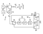
- the Figure shows a functional block diagram of a FMCW radar system for measuring the distance of a target 1 such as a filling level of a material in a container.
- the system comprises a transmit/receive unit 2 for generating a frequency modulated signal 3 to be transmitted to the target 1 and for mixing an echo signal 4 received from the target 1 with the generated frequency modulated signal 3 to produce a beat signal 5.
- a function generator 6 periodically generates a linear, e.g. triangular or sawtooth-shaped, modulation function 7 for controlling a voltage-controlled microwave oscillator 8 which generates the frequency modulated signal 3.
- the microwave signal 3 is supplied via a circulator or directional coupler 9 to an antenna 10 from which it is transmitted as a transmit signal 11 to the target 1.
- the echo 12 from the target 1 is received by the antenna 10 as the echo signal 4 after a propagation time proportional to the distance to be measured.
- the received echo signal 4 is directed by the circulator or directional coupler 9 to a mixer 13, in which it is mixed with the frequency modulated signal 3 to generate the beat signal 5.
- the beat signal 5 has a frequency corresponding to the difference of the frequencies of the signals 3 and 4. Since the frequency modulation of the transmit signal 3 is linear over time, the frequency of the beat signal 5 is directly proportional to the distance to be measured.
- the quality of the beat signal 5 is affected by unwanted echoes (clutter) so that the beat signal 5 is a complex waveform consisting of many frequency components.
- the beat signal 5 is fed via a switching unit 14 through an analog filter unit 15 which has a high pass filter 16 for reducing the dynamic range of the beat signal 5 and a low pass filter 17 for anti-aliasing purpose.
- the filtered beat signal 5 is then provided to a digital processing unit 18 comprising an analog-to- digital converter 19 and a microcontroller 20.
- the filtered and digitized beat signal 13 is subjected to a Fast Fourier Transform algorithm 21 to obtain a frequency spectrum or echo profile that is further analyzed in order to determine the target distance to be measured and provide it at an output 22.
- the microcontroller 20 includes a signal generator 23 which generates a test signal 24, here in the form of a square wave.
- the microcontroller 20 further includes a timer unit 25 which controls the switching unit 14 to intermittently disconnect the beat signal 5 from the analog filter unit 15 and instead connect the test signal 24 to the filter unit 15.
- the microcontroller 20 calculates a spectrum of the digitized filtered test signal 5 by using the Fast Fourier Transform algorithm 21 and generates a fault signal if the calculated spectrum differs from a reference spectrum by a predetermined amount.
- the square wave test signal 24 is rich in Harmonics, the resulting spectrum calculated is already the filter response at discrete frequencies. There are many ways to compare the currently obtained spectrum or filter response with the reference spectrum.
- an envelope of the peaks of the spectrum may be calculated and compared with a corresponding envelope of the reference spectrum.
- An allowable variation of the envelope of the currently obtained spectrum may be selected as a tolerance band defined above and below the envelope of the reference spectrum.
- the reference spectrum or, in the present example, its envelope is determined once during manufacturing or calibration of the FMCW radar system and stored in a memory 26 of the microcontroller 20.
- the fault signal may be outputted via output 22 as an alarm and/or is used to place the FMCW radar system into a fail-safe state.
- the time during which the test signal 24 is fed to the filter unit 5 should be sufficiently long to capture a steady-state filter response (e.g. 10 ms at a 2 kHz square wave test signal 24).
- the repetition period between two consecutive test signals 24 applied to the filter unit 5 is less than or equal to a predetermined fault reaction time of the FMCW radar system (e.g. 20 s).
Landscapes
- Engineering & Computer Science (AREA)
- Physics & Mathematics (AREA)
- Radar, Positioning & Navigation (AREA)
- Remote Sensing (AREA)
- General Physics & Mathematics (AREA)
- Computer Networks & Wireless Communication (AREA)
- Electromagnetism (AREA)
- Thermal Sciences (AREA)
- Fluid Mechanics (AREA)
- Signal Processing (AREA)
- Radar Systems Or Details Thereof (AREA)
Priority Applications (3)
| Application Number | Priority Date | Filing Date | Title |
|---|---|---|---|
| EP15156085.1A EP3059559A1 (fr) | 2015-02-23 | 2015-02-23 | Système de radar FMCW |
| CN201610037262.4A CN105911530B (zh) | 2015-02-23 | 2016-01-20 | Fmcw雷达系统 |
| US15/001,399 US10852408B2 (en) | 2015-02-23 | 2016-01-20 | Frequency-modulated continuous-wave (FMCW) |
Applications Claiming Priority (1)
| Application Number | Priority Date | Filing Date | Title |
|---|---|---|---|
| EP15156085.1A EP3059559A1 (fr) | 2015-02-23 | 2015-02-23 | Système de radar FMCW |
Publications (1)
| Publication Number | Publication Date |
|---|---|
| EP3059559A1 true EP3059559A1 (fr) | 2016-08-24 |
Family
ID=52596348
Family Applications (1)
| Application Number | Title | Priority Date | Filing Date |
|---|---|---|---|
| EP15156085.1A Withdrawn EP3059559A1 (fr) | 2015-02-23 | 2015-02-23 | Système de radar FMCW |
Country Status (3)
| Country | Link |
|---|---|
| US (1) | US10852408B2 (fr) |
| EP (1) | EP3059559A1 (fr) |
| CN (1) | CN105911530B (fr) |
Cited By (5)
| Publication number | Priority date | Publication date | Assignee | Title |
|---|---|---|---|---|
| EP3401652A1 (fr) * | 2017-05-09 | 2018-11-14 | VEGA Grieshaber KG | Jauge radar équipée d'une boucle à verrouillage de phase |
| EP3605135A1 (fr) | 2018-08-02 | 2020-02-05 | Omron Europe B.V. | Dispositif de surveillance et procédé de surveillance d'une zone de sécurité |
| CN110865349A (zh) * | 2018-08-28 | 2020-03-06 | 英飞凌科技股份有限公司 | 使用毫米波雷达在降雨和降雪条件下检测目标 |
| CN114124032A (zh) * | 2020-08-28 | 2022-03-01 | 罗克韦尔自动化技术公司 | 用于测试冗余信号路径中的滤波器的系统和方法 |
| CN116184334A (zh) * | 2021-11-29 | 2023-05-30 | 德斯拜思有限公司 | 用于产生模拟的雷达回波信号的方法和雷达目标模拟器 |
Families Citing this family (30)
| Publication number | Priority date | Publication date | Assignee | Title |
|---|---|---|---|---|
| US9846228B2 (en) | 2016-04-07 | 2017-12-19 | Uhnder, Inc. | Software defined automotive radar systems |
| US10261179B2 (en) | 2016-04-07 | 2019-04-16 | Uhnder, Inc. | Software defined automotive radar |
| WO2017187306A1 (fr) * | 2016-04-25 | 2017-11-02 | Uhnder, Inc. | Filtrage adaptatif pour atténuation d'interférence fmcw dans des systèmes de radar pmcw |
| DE102017100269A1 (de) | 2017-01-09 | 2018-07-12 | Endress+Hauser SE+Co. KG | Verfahren zur Detektion eines Fehlerzustandes an einem FMCW-basierten Füllstandsmessgerät |
| WO2018146530A1 (fr) | 2017-02-10 | 2018-08-16 | Uhnder, Inc. | Corrélation basée sur une fft à complexité réduite pour un radar automobile |
| US9971020B1 (en) | 2017-02-10 | 2018-05-15 | Uhnder, Inc. | Radar data buffering |
| US10097287B1 (en) * | 2017-09-07 | 2018-10-09 | Nxp B.V. | RF radar device BIST using secondary modulation |
| CH714313A1 (de) * | 2017-11-09 | 2019-05-15 | Elesta Gmbh Ostfildern De Zweigniederlassung Bad Ragaz | Vorrichtung mit einem Sensor und einem Betätiger, insbesondere zur Verwendung als Türkontaktschalter, und Verfahren zum Testen der Vorrichtung. |
| DE102017222272B4 (de) * | 2017-12-08 | 2024-05-23 | Vega Grieshaber Kg | Radargerät zur Objekterkennung |
| US11105890B2 (en) | 2017-12-14 | 2021-08-31 | Uhnder, Inc. | Frequency modulated signal cancellation in variable power mode for radar applications |
| CN108195443B (zh) * | 2017-12-29 | 2020-10-02 | 北京奥特美克科技股份有限公司 | 水位测量方法、系统及设备 |
| CN108535719B (zh) * | 2017-12-29 | 2020-06-16 | 西安电子科技大学 | 基于多普勒频谱重心校正的调频连续波着陆雷达测速方法 |
| US11474225B2 (en) | 2018-11-09 | 2022-10-18 | Uhnder, Inc. | Pulse digital mimo radar system |
| US11204410B2 (en) * | 2019-02-11 | 2021-12-21 | Nxp B.V. | Radar-based communication |
| US11681017B2 (en) | 2019-03-12 | 2023-06-20 | Uhnder, Inc. | Method and apparatus for mitigation of low frequency noise in radar systems |
| KR102843866B1 (ko) * | 2019-03-29 | 2025-08-11 | 한국전자통신연구원 | 레이더 및 레이더의 제어방법 |
| US11513190B2 (en) * | 2019-05-31 | 2022-11-29 | Texas Instruments Incorporated | Methods and apparatus to test radar integrated circuits |
| CN110187317B (zh) * | 2019-06-17 | 2021-01-05 | 北京无线电测量研究所 | 一种fmcw信号非线性误差补偿方法、装置及存储介质 |
| CN112782674A (zh) * | 2019-11-07 | 2021-05-11 | 上海禾赛科技股份有限公司 | 激光雷达及其控制方法 |
| EP3822663B1 (fr) * | 2019-11-15 | 2022-02-23 | Axis AB | Procédé, produit-programme d'ordinateur, appareil et système de radar à onde continue à fréquence modulée |
| DE102019132149A1 (de) * | 2019-11-27 | 2021-05-27 | Endress+Hauser SE+Co. KG | FMCW-basiertes Abstandsmessgerät |
| WO2021144710A2 (fr) | 2020-01-13 | 2021-07-22 | Uhnder, Inc. | Procédé et système pour le fonctionnement multi-puce de systèmes radar |
| JP2021156713A (ja) * | 2020-03-26 | 2021-10-07 | 古河電気工業株式会社 | レーダ装置 |
| US11550027B2 (en) | 2020-05-04 | 2023-01-10 | Nxp B.V. | Predistortion technique for joint radar/communication systems |
| CN114076941B (zh) * | 2020-08-21 | 2025-04-22 | 上海禾赛科技有限公司 | 利用调频连续波探测的方法、雷达和计算机可读存储介质 |
| CN113589242B (zh) * | 2021-07-30 | 2024-04-30 | 米传科技(上海)有限公司 | 一种毫米波雷达接收回路频谱特性测量系统及方法 |
| US12007465B2 (en) | 2021-10-19 | 2024-06-11 | Nxp B.V. | Radar apparatus and method with content embedded in the radar signal |
| US12498452B2 (en) | 2021-12-02 | 2025-12-16 | Robert Bosch Gmbh | Radar system with enhanced processing for increased contrast ratio, improved angular separability and accuracy, and elimination of ghost targets in a single-snapshot |
| CN114185013A (zh) * | 2021-12-03 | 2022-03-15 | 江西洪都航空工业集团有限责任公司 | 一种基于实验室的低高度无线电回波信号模拟方法和系统 |
| DE102022127132A1 (de) * | 2022-10-17 | 2024-04-18 | Vega Grieshaber Kg | Adaptives SFC-Filter für Füllstandsensoren |
Citations (1)
| Publication number | Priority date | Publication date | Assignee | Title |
|---|---|---|---|---|
| EP2660568A1 (fr) * | 2012-05-03 | 2013-11-06 | VEGA Grieshaber KG | Compensation d'erreurs par la mesure de la fonction de filtre STC |
Family Cites Families (18)
| Publication number | Priority date | Publication date | Assignee | Title |
|---|---|---|---|---|
| US5198748A (en) * | 1991-10-28 | 1993-03-30 | The United States Of America As Represented By The Secretary Of The Air Force | Frequency measurement receiver with bandwidth improvement through synchronized phase shifted sampling |
| JP3045977B2 (ja) * | 1997-06-18 | 2000-05-29 | 本田技研工業株式会社 | Fm−cwレーダ装置 |
| JP3011164B2 (ja) * | 1997-11-14 | 2000-02-21 | 日本電気株式会社 | レーダ装置 |
| JP3534164B2 (ja) * | 1998-04-28 | 2004-06-07 | トヨタ自動車株式会社 | Fm−cwレーダ装置 |
| JP2003028951A (ja) * | 2001-07-11 | 2003-01-29 | Fujitsu Ten Ltd | レーダ装置 |
| US20030061163A1 (en) * | 2001-09-27 | 2003-03-27 | Durfield Richard C. | Method and apparatus for verification/authorization by credit or debit card owner of use of card concurrently with merchant transaction |
| WO2003050370A1 (fr) * | 2001-12-10 | 2003-06-19 | Omron Co., Ltd. | Capteur d'objet et controleur |
| JP3944130B2 (ja) | 2003-07-08 | 2007-07-11 | 三菱電機株式会社 | 移動体のレ−ダ方式、レ−ダ装置、レーダ信号処理方法、及びレーダ信号処理装置 |
| WO2005124388A1 (fr) | 2004-06-21 | 2005-12-29 | Fujitsu Ten Limited | Appareil radar |
| US7327308B2 (en) | 2005-04-28 | 2008-02-05 | Chung Shan Institute Of Science And Technology, Armaments Bureau, M.N.D. | Programmable method and test device for generating target for FMCW radar |
| JP2008232832A (ja) | 2007-03-20 | 2008-10-02 | Denso Corp | 干渉判定方法,fmcwレーダ |
| DE102008050117A1 (de) * | 2008-10-06 | 2010-04-08 | Endress + Hauser Gmbh + Co. Kg | Kalibration einer Radareinheit mit gerätespezifischen Korrekturkurven |
| CN101807077A (zh) | 2009-02-17 | 2010-08-18 | 扬州市万泰电器厂有限公司 | 一种具有隐性故障检测的伺服系统 |
| CA2709762C (fr) * | 2009-07-16 | 2018-03-06 | Simon Fraser University | Dispositif et methodes de detection de rotation |
| KR101223539B1 (ko) * | 2010-12-15 | 2013-01-21 | 에스케이하이닉스 주식회사 | 반도체 집적 회로 장치 |
| JP5312503B2 (ja) * | 2011-03-16 | 2013-10-09 | 三菱電機株式会社 | レーダ装置 |
| DE102011115309A1 (de) * | 2011-09-29 | 2013-04-04 | Infineon Technologies Ag | Radarschaltung, Radarsystem und Verfahren zum Testen einer Verbindung zwischen einer Radarschaltung und einer Radarantenne in einem Fahrzeug |
| JP5912879B2 (ja) * | 2012-05-31 | 2016-04-27 | 株式会社デンソー | レーダ装置 |
-
2015
- 2015-02-23 EP EP15156085.1A patent/EP3059559A1/fr not_active Withdrawn
-
2016
- 2016-01-20 US US15/001,399 patent/US10852408B2/en active Active
- 2016-01-20 CN CN201610037262.4A patent/CN105911530B/zh not_active Expired - Fee Related
Patent Citations (2)
| Publication number | Priority date | Publication date | Assignee | Title |
|---|---|---|---|---|
| EP2660568A1 (fr) * | 2012-05-03 | 2013-11-06 | VEGA Grieshaber KG | Compensation d'erreurs par la mesure de la fonction de filtre STC |
| WO2013164456A1 (fr) | 2012-05-03 | 2013-11-07 | Vega Grieshaber Kg | Compensation d'erreur par la mesure de la fonction de filtre gtv |
Non-Patent Citations (3)
| Title |
|---|
| FRENCH R C: "TRANSFER FUNCTION MEASUREMENT USING FAST PULSES", ELECTRONIC ENGINEERING, MORGAN-GRAMPIAN LTD. LONDON, GB, 1 August 1996 (1996-08-01), pages 516 - 519, XP009017627, ISSN: 0013-4902 * |
| KROEGER H ET AL: "LINEARE SYSTEME MIT RATIONALER UEBERTRAGUNGSFUNKTION IM FALLE ZWEIER POLSTELLEN BEI ERREGUNG DURCH EINEN PERIODISCHEN RECHTECKPULS", ATM. ARCHIV FUER TECHNISCHES MESSEN UND INDUSTRIELLEMESSTECHNIK, OLDENBOURG VERLAG, MUENCHEN, DE, no. 413, 1 June 1970 (1970-06-01), pages 131 - 134, XP009017752, ISSN: 0365-7418 * |
| ULRICH KARRENBERG: "Signale Prozesse Systeme", 1 January 2001, SPRINGER-VERLAG, Heidelberg Berlin, York New, ISBN: 978-3-54-041769-9, ISSN: 0012-0472, article "Kapitel 6: Systemanalyse", pages: 141 - 174, XP055200378 * |
Cited By (10)
| Publication number | Priority date | Publication date | Assignee | Title |
|---|---|---|---|---|
| EP3401652A1 (fr) * | 2017-05-09 | 2018-11-14 | VEGA Grieshaber KG | Jauge radar équipée d'une boucle à verrouillage de phase |
| EP3605135A1 (fr) | 2018-08-02 | 2020-02-05 | Omron Europe B.V. | Dispositif de surveillance et procédé de surveillance d'une zone de sécurité |
| CN110865349A (zh) * | 2018-08-28 | 2020-03-06 | 英飞凌科技股份有限公司 | 使用毫米波雷达在降雨和降雪条件下检测目标 |
| CN114124032A (zh) * | 2020-08-28 | 2022-03-01 | 罗克韦尔自动化技术公司 | 用于测试冗余信号路径中的滤波器的系统和方法 |
| EP3961228A1 (fr) * | 2020-08-28 | 2022-03-02 | Rockwell Automation Technologies, Inc. | Système et procédé de test de filtres dans des trajets de signaux redondants |
| US11496254B2 (en) | 2020-08-28 | 2022-11-08 | Rockwell Automation Technologies, Inc. | System and method for testing filters in redundant signal paths |
| US11716178B2 (en) | 2020-08-28 | 2023-08-01 | Rockwell Automation Technologies, Inc. | Safety rated input module for an industrial controller |
| EP4254088A3 (fr) * | 2020-08-28 | 2023-11-15 | Rockwell Automation Technologies, Inc. | Système et procédé de test de filtres dans des voies de signal redondantes |
| CN114124032B (zh) * | 2020-08-28 | 2025-06-24 | 罗克韦尔自动化技术公司 | 用于测试冗余信号路径中的滤波器的系统和方法 |
| CN116184334A (zh) * | 2021-11-29 | 2023-05-30 | 德斯拜思有限公司 | 用于产生模拟的雷达回波信号的方法和雷达目标模拟器 |
Also Published As
| Publication number | Publication date |
|---|---|
| US20160245909A1 (en) | 2016-08-25 |
| CN105911530A (zh) | 2016-08-31 |
| CN105911530B (zh) | 2019-10-15 |
| US10852408B2 (en) | 2020-12-01 |
Similar Documents
| Publication | Publication Date | Title |
|---|---|---|
| US10852408B2 (en) | Frequency-modulated continuous-wave (FMCW) | |
| US8847816B2 (en) | Calibration of a radar unit with device-specific correction curves | |
| US9448301B2 (en) | Calibrated radar apparatus and associated methods | |
| US9910135B2 (en) | FMCW radar self-test | |
| US20240094371A1 (en) | Radar device, method of detecting failure of radar device, and method of operating radar device | |
| CN104024882B (zh) | 雷达装置和用于识别雷达装置接收波道的故障的方法 | |
| US9612147B2 (en) | Radar level gauge system with multiple receiver branches | |
| US10371799B1 (en) | Methods of calibration for radar apparatus | |
| WO2014019948A1 (fr) | Procédé servant à déterminer et/ou à surveiller le niveau de remplissage d'un milieu dans un récipient | |
| US9780833B2 (en) | De-embedding cable effect for waveform monitoring for arbitrary waveform and function generator | |
| KR20130005803A (ko) | 케이블 결함 진단 시스템 및 방법 | |
| US12135389B2 (en) | Methods and apparatuses for testing one or more reception paths in a radar receiver | |
| US11313967B2 (en) | Self-testing measuring system | |
| DE2835703C2 (fr) | ||
| EP4222507A1 (fr) | Dispositif et procédé de mesure de débit de fluide à résonance acoustique | |
| US20190360853A1 (en) | Method for detecting a fault state at an fmcw-based filling level measuring device | |
| CN102445687A (zh) | 具有相位调整振荡器的雷达传感器 | |
| KR101044000B1 (ko) | 도플러 주파수 측정방법과 장치 및 이를 이용한 레이더 세트의 시험 시스템 | |
| US20160320217A1 (en) | Self-calibrating linear voltage differential transformer demodulator | |
| US10866133B2 (en) | Capacitive limit level switch | |
| KR20120132598A (ko) | 부분방전 신호측정 방법과 장치 | |
| US20120310583A1 (en) | Device and method for testing apd measuring device | |
| Cheon et al. | A Novel Over-The-Air Measurement Method for Linear Frequency Modulation Signals Using Continuous Wave Receiver | |
| RU2568408C1 (ru) | Способ измерения параметров антенных систем с использованием метода пространственно-временной селекции и системы автоматизированной настройки для его осуществления | |
| RU2334953C2 (ru) | Способ радиоволнового измерения уровня |
Legal Events
| Date | Code | Title | Description |
|---|---|---|---|
| PUAI | Public reference made under article 153(3) epc to a published international application that has entered the european phase |
Free format text: ORIGINAL CODE: 0009012 |
|
| AK | Designated contracting states |
Kind code of ref document: A1 Designated state(s): AL AT BE BG CH CY CZ DE DK EE ES FI FR GB GR HR HU IE IS IT LI LT LU LV MC MK MT NL NO PL PT RO RS SE SI SK SM TR |
|
| AX | Request for extension of the european patent |
Extension state: BA ME |
|
| STAA | Information on the status of an ep patent application or granted ep patent |
Free format text: STATUS: REQUEST FOR EXAMINATION WAS MADE |
|
| 17P | Request for examination filed |
Effective date: 20170224 |
|
| RBV | Designated contracting states (corrected) |
Designated state(s): AL AT BE BG CH CY CZ DE DK EE ES FI FR GB GR HR HU IE IS IT LI LT LU LV MC MK MT NL NO PL PT RO RS SE SI SK SM TR |
|
| RAP1 | Party data changed (applicant data changed or rights of an application transferred) |
Owner name: SIEMENS AKTIENGESELLSCHAFT |
|
| STAA | Information on the status of an ep patent application or granted ep patent |
Free format text: STATUS: EXAMINATION IS IN PROGRESS |
|
| 17Q | First examination report despatched |
Effective date: 20180426 |
|
| REG | Reference to a national code |
Ref country code: DE Ref legal event code: R079 Free format text: PREVIOUS MAIN CLASS: G01F0023284000 Ipc: G01S0007400000 |
|
| GRAP | Despatch of communication of intention to grant a patent |
Free format text: ORIGINAL CODE: EPIDOSNIGR1 |
|
| STAA | Information on the status of an ep patent application or granted ep patent |
Free format text: STATUS: GRANT OF PATENT IS INTENDED |
|
| RIC1 | Information provided on ipc code assigned before grant |
Ipc: G01F 23/284 20060101ALI20240207BHEP Ipc: G01S 13/34 20060101ALI20240207BHEP Ipc: G01S 7/40 20060101AFI20240207BHEP |
|
| RIN1 | Information on inventor provided before grant (corrected) |
Inventor name: SERBAN, MIHAI-GABRIEL Inventor name: LIU, JING Inventor name: DUIVENVOORDEN, JOHANNES THEODORUS CORNELIS Inventor name: ASLETT, ALAN |
|
| INTG | Intention to grant announced |
Effective date: 20240227 |
|
| GRAJ | Information related to disapproval of communication of intention to grant by the applicant or resumption of examination proceedings by the epo deleted |
Free format text: ORIGINAL CODE: EPIDOSDIGR1 |
|
| STAA | Information on the status of an ep patent application or granted ep patent |
Free format text: STATUS: EXAMINATION IS IN PROGRESS |
|
| GRAP | Despatch of communication of intention to grant a patent |
Free format text: ORIGINAL CODE: EPIDOSNIGR1 |
|
| STAA | Information on the status of an ep patent application or granted ep patent |
Free format text: STATUS: GRANT OF PATENT IS INTENDED |
|
| INTC | Intention to grant announced (deleted) | ||
| INTG | Intention to grant announced |
Effective date: 20240731 |
|
| STAA | Information on the status of an ep patent application or granted ep patent |
Free format text: STATUS: THE APPLICATION IS DEEMED TO BE WITHDRAWN |
|
| 18D | Application deemed to be withdrawn |
Effective date: 20241203 |