EP3059850A1 - Mobile induktions- und stromerzeugungsvorrichtung - Google Patents
Mobile induktions- und stromerzeugungsvorrichtung Download PDFInfo
- Publication number
- EP3059850A1 EP3059850A1 EP13895739.4A EP13895739A EP3059850A1 EP 3059850 A1 EP3059850 A1 EP 3059850A1 EP 13895739 A EP13895739 A EP 13895739A EP 3059850 A1 EP3059850 A1 EP 3059850A1
- Authority
- EP
- European Patent Office
- Prior art keywords
- movement
- induction
- magnetic element
- magnetic
- displacement
- Prior art date
- Legal status (The legal status is an assumption and is not a legal conclusion. Google has not performed a legal analysis and makes no representation as to the accuracy of the status listed.)
- Withdrawn
Links
Images



Classifications
-
- H—ELECTRICITY
- H02—GENERATION; CONVERSION OR DISTRIBUTION OF ELECTRIC POWER
- H02K—DYNAMO-ELECTRIC MACHINES
- H02K7/00—Arrangements for handling mechanical energy structurally associated with dynamo-electric machines, e.g. structural association with mechanical driving motors or auxiliary dynamo-electric machines
- H02K7/18—Structural association of electric generators with mechanical driving motors, e.g. with turbines
- H02K7/1892—Generators with parts oscillating or vibrating about an axis
-
- B—PERFORMING OPERATIONS; TRANSPORTING
- B62—LAND VEHICLES FOR TRAVELLING OTHERWISE THAN ON RAILS
- B62J—CYCLE SADDLES OR SEATS; AUXILIARY DEVICES OR ACCESSORIES SPECIALLY ADAPTED TO CYCLES AND NOT OTHERWISE PROVIDED FOR, e.g. ARTICLE CARRIERS OR CYCLE PROTECTORS
- B62J6/00—Arrangement of optical signalling or lighting devices on cycles; Mounting or supporting thereof; Circuits therefor
- B62J6/06—Arrangement of lighting dynamos or drives therefor
-
- H—ELECTRICITY
- H02—GENERATION; CONVERSION OR DISTRIBUTION OF ELECTRIC POWER
- H02K—DYNAMO-ELECTRIC MACHINES
- H02K21/00—Synchronous motors having permanent magnets; Synchronous generators having permanent magnets
- H02K21/12—Synchronous motors having permanent magnets; Synchronous generators having permanent magnets with stationary armatures and rotating magnets
- H02K21/14—Synchronous motors having permanent magnets; Synchronous generators having permanent magnets with stationary armatures and rotating magnets with magnets rotating within the armatures
-
- H—ELECTRICITY
- H02—GENERATION; CONVERSION OR DISTRIBUTION OF ELECTRIC POWER
- H02K—DYNAMO-ELECTRIC MACHINES
- H02K35/00—Generators with reciprocating, oscillating or vibrating coil system, magnet, armature or other part of the magnetic circuit
- H02K35/02—Generators with reciprocating, oscillating or vibrating coil system, magnet, armature or other part of the magnetic circuit with moving magnets and stationary coil systems
-
- H—ELECTRICITY
- H02—GENERATION; CONVERSION OR DISTRIBUTION OF ELECTRIC POWER
- H02K—DYNAMO-ELECTRIC MACHINES
- H02K49/00—Dynamo-electric clutches; Dynamo-electric brakes
- H02K49/10—Dynamo-electric clutches; Dynamo-electric brakes of the permanent-magnet type
- H02K49/102—Magnetic gearings, i.e. assembly of gears, linear or rotary, by which motion is magnetically transferred without physical contact
Definitions
- the present invention relates to a generator converting slight movement or vibration into electrical energy.
- the primary objective of the present invention is to provide a novel movement induction generator, which employs a vibration-induced generation technology using multiple magnetic elements with relative movement.
- the problem of slight vibration or movement cannot generate electricity with good collecting value can be solved, providing significant energy converting and collecting effects for slight vibration or movement.
- the present invention is very suitable for practical usage.
- a movement induction generator in accordance the present invention comprises an induction movement magnetic element, a displacement magnetic element, and an induction coil, wherein:
- the adjacent magnetic poles with opposite polarities of the displacement magnetic element change their polarities repeatedly relative to the induction movement magnetic element when they move along the movement trajectory, making the induction movement magnetic element to move along the passive movement trajectory.
- the induction movement magnetic element comprises at least one magnetic pole set and a rotation axle, and the at least one magnetic pole set is disposed in a radical direction of the rotation axle and rotates around the rotation axle.
- the induction movement magnetic element is disc-shaped and comprises a magnetic pole set, and the magnetic pole set has a semicircular N-pole and a semicircular S-pole;
- the rotation axle is disposed at an axial direction of the induction movement magnetic element, and the direction of the passive movement trajectory is the circumferentially tangent direction of the rotation axle.
- the two adjacent magnetic poles with opposite polarities of one magnetic pole set of the displacement magnetic element are N-pole and S-pole of a block magnet
- the displacement magnetic element comprises a movement promotion element connected to or contacted with the block magnet
- the displacement magnetic element comprises multiple magnets disposed in a circular arrangement and two adjacent magnets have opposite magnetic poles, and the circular arrangement of two adjacent magnetic poles with opposite polarities of each magnet is toward a radical direction or an axial direction of a circle.
- the displacement magnetic element has a single magnetic pole toward the direction of the rotation axle of the induction movement magnetic element and moves back and forth in the radical direction of the rotation axle or moves eccentrically in the axial direction of the rotation axle.
- the induction coil is disposed around and outside the induction movement magnetic element.
- the induction coil is connected to a load, and the load is a light-emitting device, a wireless signal transmitting module, a sensor, or an electricity storage device.
- the present invention has obvious advantages and benefits compared to the prior art.
- the movement induction generator in accordance the present invention has at least the following advantages and benefits:
- the present invention relates to a movement induction generator, which comprises an induction movement magnetic element, a displacement magnetic element, and an induction coil.
- the induction movement magnetic element is able to be driven by an external magnetic field to move along a passive movement trajectory, and the induction movement magnetic element comprises at least one magnetic pole set.
- the displacement magnetic element has at least one magnetic pole set each having two adjacent magnetic poles with opposite polarities and the at least one magnetic pole set moves along a movement trajectory relative to the induction movement magnetic element, the displacement magnetic element actuates the induction movement magnetic element to move along the passive movement trajectory.
- the induction coil is disposed adjacent to the induction movement magnetic element or the displacement magnetic element, induced by an alternating magnetic field generated by the movements of the induction movement magnetic element or the displacement magnetic element, and generates an induction current due to the alternating magnetic field.
- Fig. 1 is a schematic diagram of a construction of a first preferred embodiment in accordance with the present invention.
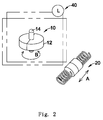
- Fig. 2 is a schematic diagram of a construction of a second preferred embodiment in accordance with the present invention.
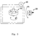
- Fig. 3 is a schematic diagram of a construction of a third preferred embodiment in accordance with the present invention.
- Fig. 4 is a schematic diagram of a construction of a forth preferred embodiment in accordance with the present invention.
- a preferred embodiment of the movement induction generator in accordance with the present invention comprises an induction movement magnetic element (10), a displacement magnetic element (20), and an induction coil (30).
- the induction movement magnetic element (10) is able to be driven by an external magnetic field to move along a passive movement trajectory (B).
- the induction movement magnetic element (10) of this embodiment comprises at least one magnetic pole set (12).
- the magnetic pole set (12) is disposed in a radical direction of the induction movement magnetic element (10).
- the magnetic pole set (12) rotates around a rotation axle (14).
- the magnetic pole set (12) has a major magnetic pole direction pointing from S-pole to N-pole.
- the major magnetic pole direction is preferably disposed radically relative to the rotation axle (14) or an angle between the magnetic pole direction and the rotation axle (14) in the radical direction is less than 30 degrees.
- the induction movement magnetic element (10) of this embodiment is disc-shaped and comprises a magnetic pole set (12).
- the magnetic pole set (12) has a semicircular N-pole and a semicircular S-pole.
- the rotation axle (14) is disposed at an axial direction of the induction movement magnetic element (10).
- the direction of the passive movement trajectory (B) is the circumferentially tangent direction of the rotation axle (14).
- the magnetic field of the displacement magnetic element (20) can move along a movement trajectory (A) relative to the induction movement magnetic element (10).
- the so-called movement along the movement trajectory (A) has the meaning described below.
- At least one magnetic pole set of the displacement magnetic element (20) each having two adjacent magnetic poles (24) with opposite polarities has a positional relationship with the induction movement magnetic element (10).
- the displacement magnetic element (20) moves or rotates along the movement trajectory (A).
- the so-called two adjacent magnetic poles with opposite polarities is not limited to N-pole and S-pole of the same magnet, but can be two adjacent or contacting magnets whose N-poles and S-poles are disposed opposite each other.
- the movement direction of the displacement magnetic element (20) along the movement trajectory (A) can correspond with the axial direction of the induction movement magnetic element (10) as shown in Fig. 1 or a tangent direction when the induction movement magnetic element (10) is rotated as shown in Fig. 2 .
- the movement trajectory (A) can be linear as shown in Fig. 1 , or an arc path as shown in Figs. 3 and 4 .
- the polarities of the magnetic poles will change repeatedly relative to the induction movement magnetic element (10) when the adjacent magnetic poles with opposite polarities of the displacement magnetic element (20) move along the movement trajectory (A).
- the induction movement magnetic element (10) will be attracted or guided to move along the passive movement trajectory (B).
- a movement promotion element (22) can be used and contacted with the two adjacent magnetic poles (24) with opposite polarities.
- the two adjacent magnetic poles (24) with opposite polarities are N-pole and S-pole of a block magnet.
- the movement promotion element (22) is a spring or a reed or another vibration or rotation maintaining structure connected to the block magnet. When the block magnet moves because of external conditions, the spring or reed can extend the movement of the block magnet.
- Fig. 5 is a schematic diagram of the forth preferred embodiment in accordance with the present invention in use.
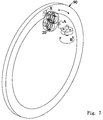
- Fig. 7 is another schematic diagram of the forth preferred embodiment in accordance with the present invention in use.
- the displacement magnetic element (20) may comprise multiple magnets disposed in a circular arrangement and two adjacent magnets have opposite magnetic poles.
- the displacement magnetic element (20) comprises multiple magnetic poles set each having two adjacent magnetic poles with opposite polarities.
- the circular arrangement of two adjacent magnetic poles with opposite polarities of each magnet is preferably toward a radical direction (as shown in Figs. 4 and 5 ) or an axial direction (as shown in Fig. 7 ) of a circle.
- each magnetic pole is rotated along the movement trajectory (A)
- the magnetic poles of the displacement magnetic element (20) keep changing, causing the magnetic pole set (12) of the induction movement magnetic element (10) moves along the passive movement trajectory (B) with alternating.
- the above-mentioned rotation maintaining structure may be a winding structure or a ratchet rotating structure, and etc. After winding up, the winding structure can keep the displacement magnetic element (20) rotating for a period of time.
- the ratchet rotating structure can keep rotating in a specific direction for a period of time by pressing or swinging the ratchet rotating structure.
- magnets disposed in the circular arrangement can be close to a moving metal (90).
- the moving metal (90) When the moving metal (90) has a relative movement relative to the displacement magnetic element (20), the moving metal (90) will be induced magnetically and generate a eddy current, bringing each magnet of the displacement magnetic element (20) to rotate along the movement trajectory (A).
- the induction movement magnetic element (10) is then induced by the alternating displacement magnetic element (20) and rotates or swings.
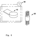
- Fig. 6 is a schematic diagram of a construction of a fifth preferred embodiment in accordance with the present invention.
- the induction movement magnetic element (10) may be a magnet with a spring or a reed mounted thereon.
- the displacement magnetic element (20) moves along the movement trajectory (A)
- the induction movement magnetic element (10) is attracted or repelled and vibrates.
- the induction coil (30) is disposed adjacent to the induction movement magnetic element (10) or/and the displacement magnetic element (20), induced by an alternating magnetic field generated by the movements of the induction movement magnetic element (10) or/and the displacement magnetic element (20).
- the induction coil (30) generates an induction current due to the alternating magnetic field.
- the induction coil (30) may be connected to a load (40), so the load can work due to the induction current.
- the winding direction of the induction coil (30) as shown in Figs. 1 , 2 , 3 , 4 , and 6 is only for illustration.
- the preferable winding direction for generating the induction current must correspond with the direction of the alternating magnetic field.
- the principle of better winding is known in the art and unnecessary details are omitted herein.
- the load (40) may be a light-emitting device (e.g. LED or OLED), a wireless signal transmitting module (e.g. RF transmitter or WIFI transmitter), a sensor (e.g. temperature, pressure, humidity or heart rate), or an electricity storage device (e.g. rechargeable battery or super capacitor).
- a light-emitting device e.g. LED or OLED
- a wireless signal transmitting module e.g. RF transmitter or WIFI transmitter
- a sensor e.g. temperature, pressure, humidity or heart rate
- an electricity storage device e.g. rechargeable battery or super capacitor
- the induction coil (30) can be disposed around and outside the induction movement magnetic element (10).
- the displacement magnetic element (20) moves along the movement trajectory (A) due to movement or vibration from the external conditions.
- the induction coil (30) generates a current input to the load (40) due to the alternating magnetic field generated from the movement of the induction movement magnetic element (10).
- a portion of the induction movement magnetic element (10) and a portion of the induction coil (30) can be mounted in the same housing.
- the displacement magnetic element (20) can have the movement promotion element (22), vibration or movement of the housing can be extended when the housing is forced to move or vibrate.
- the induction movement magnetic element (10) can be driven to have a relative movement and the induction coil (30) is induced to generate electricity.
- the induction movement magnetic element (10) and the displacement magnetic element (20) can be mounted on a runner or a bicycle.
- the displacement magnetic element (20) can vibrate with the movement of the runner or the bicycle so as to achieve the object of electricity generation.
- the displacement magnetic element (20) can also have a single magnetic pole toward the axial direction of the rotation axle (14) of the induction movement magnetic element (10) and moves back and forth in the radical direction of the rotation axle (14) or moves eccentrically in the axial direction of the rotation axle (14).
- the induction movement magnetic element (10) can comprises two magnetic poles with opposite polarities, the magnetic poles mutually attracting the displacement magnetic element (20) will move as the displacement magnetic element (20) moves, making the induction movement magnetic element (10) swing or rotate and generating an electricity output.
Landscapes
- Engineering & Computer Science (AREA)
- Power Engineering (AREA)
- Mechanical Engineering (AREA)
- Reciprocating, Oscillating Or Vibrating Motors (AREA)
- Chemical & Material Sciences (AREA)
- Combustion & Propulsion (AREA)
- General Engineering & Computer Science (AREA)
- Connection Of Motors, Electrical Generators, Mechanical Devices, And The Like (AREA)
- General Electrical Machinery Utilizing Piezoelectricity, Electrostriction Or Magnetostriction (AREA)
- Measurement Of Length, Angles, Or The Like Using Electric Or Magnetic Means (AREA)
Applications Claiming Priority (1)
| Application Number | Priority Date | Filing Date | Title |
|---|---|---|---|
| PCT/CN2013/001232 WO2015054803A1 (zh) | 2013-10-14 | 2013-10-14 | 移动感应及发电装置 |
Publications (2)
| Publication Number | Publication Date |
|---|---|
| EP3059850A1 true EP3059850A1 (de) | 2016-08-24 |
| EP3059850A4 EP3059850A4 (de) | 2017-06-07 |
Family
ID=52827513
Family Applications (1)
| Application Number | Title | Priority Date | Filing Date |
|---|---|---|---|
| EP13895739.4A Withdrawn EP3059850A4 (de) | 2013-10-14 | 2013-10-14 | Mobile induktions- und stromerzeugungsvorrichtung |
Country Status (7)
| Country | Link |
|---|---|
| US (1) | US10033249B2 (de) |
| EP (1) | EP3059850A4 (de) |
| JP (1) | JP6092414B2 (de) |
| KR (1) | KR20160042134A (de) |
| CN (2) | CN108266343A (de) |
| CA (1) | CA2926957A1 (de) |
| WO (1) | WO2015054803A1 (de) |
Cited By (5)
| Publication number | Priority date | Publication date | Assignee | Title |
|---|---|---|---|---|
| EP3499032A1 (de) * | 2017-12-13 | 2019-06-19 | Wistron Corporation | Mitkonstruierte stromerzeugungsvorrichtung |
| WO2021102316A1 (en) * | 2019-11-21 | 2021-05-27 | Wepower Technologies Llc | Tangentially actuated magnetic momentum transfer generator |
| US11251007B2 (en) | 2017-10-30 | 2022-02-15 | Wepower Technologies Llc | Magnetic momentum transfer generator |
| USRE49840E1 (en) | 2012-04-06 | 2024-02-13 | Wepower Technologies Llc | Electrical generator with rotational gaussian surface magnet and stationary coil |
| US12062965B2 (en) | 2019-07-20 | 2024-08-13 | Wepower Technologies Llc | Offset triggered cantilever actuated generator |
Families Citing this family (12)
| Publication number | Priority date | Publication date | Assignee | Title |
|---|---|---|---|---|
| US20140246960A1 (en) * | 2013-03-04 | 2014-09-04 | Stephen Smith | Energy transfer system and method |
| TW201723307A (zh) * | 2015-12-31 | 2017-07-01 | 三宅圀博 | 風力發電裝置及其轉子組件 |
| TW201725314A (zh) * | 2016-01-05 | 2017-07-16 | 三宅圀博 | 雙殼式流體發電裝置及其轉子組件 |
| JP6464339B2 (ja) * | 2017-01-05 | 2019-02-06 | 信 羽鳥 | 発電装置 |
| US10141804B2 (en) * | 2017-01-11 | 2018-11-27 | Infinitum Electric Inc. | System, method and apparatus for modular axial field rotary energy device |
| JP2018157616A (ja) * | 2017-03-15 | 2018-10-04 | Thk株式会社 | 直動装置における発電システム |
| US10855158B2 (en) * | 2018-04-19 | 2020-12-01 | Watasensor, Inc. | Magnetic power generation |
| KR101961108B1 (ko) * | 2018-08-16 | 2019-03-25 | 전북대학교산학협력단 | 발전장치 및 그 제어 방법 |
| EP3966451B1 (de) * | 2019-05-10 | 2025-12-31 | Volvo Construction Equipment AB | Umwandlung von schwingungsenergie in elektrische energie in einer vibrationsverdichtungsmaschine |
| CN111248846B (zh) * | 2020-01-15 | 2021-02-09 | 吉林大学 | 一种安装有辅助护理功能的消化胃镜装置 |
| CN112883745A (zh) * | 2021-02-03 | 2021-06-01 | 广西电网有限责任公司电力科学研究院 | 一种无源非接触式矩阵磁场取能器 |
| FR3131657A1 (fr) * | 2021-12-30 | 2023-07-07 | Commissariat A L'energie Atomique Et Aux Energies Alternatives | Récuperateur d'energie a large gamme de vitesse de fonctionnement |
Family Cites Families (64)
| Publication number | Priority date | Publication date | Assignee | Title |
|---|---|---|---|---|
| US3360704A (en) * | 1965-04-22 | 1967-12-26 | Kohlhagen Walter | Spring-type electromechanical oscillator |
| JPS553677B2 (de) * | 1972-09-14 | 1980-01-26 | ||
| US4207773A (en) * | 1976-11-04 | 1980-06-17 | Stahovic Robert F | Magnetic piston machine |
| DK152477C (da) * | 1977-03-14 | 1988-08-01 | Burundukov Valentin M | Elektrodynamisk transducer til omsaetning af mekaniske svingninger til elektriske signaler eller omvendt, samt stereofonisk og monofonisk pickuphoved og elektrodynamisk mikrofon med en saadan transducer. |
| DE2817169C2 (de) * | 1978-04-20 | 1986-10-23 | Robert Bosch Gmbh, 7000 Stuttgart | Einrichtung zur Abgabe von Impulsen |
| US4196365A (en) * | 1978-07-03 | 1980-04-01 | Doy Presley | Magnetic motor having rotating and reciprocating permanent magnets |
| DE3112709C2 (de) * | 1981-03-31 | 1986-11-27 | Doduco KG Dr. Eugen Dürrwächter, 7530 Pforzheim | Induktiver Drehgeber |
| US4598221A (en) * | 1985-01-23 | 1986-07-01 | Lawson William J | Permanent magnet motor having rockable rotor magnets |
| US4901357A (en) * | 1987-01-20 | 1990-02-13 | Albright Eugene A | Electromagnetic transducer |
| US5347186A (en) * | 1992-05-26 | 1994-09-13 | Mcq Associates, Inc. | Linear motion electric power generator |
| US5455474A (en) * | 1992-06-23 | 1995-10-03 | Magnetic Revolutions Limited L.L.C. | Magnetic motor construction |
| DE4223826C2 (de) * | 1992-07-20 | 1994-05-11 | Gerd Schuesler | Magnetisches Parallelwellengetriebe |
| DE4342069C2 (de) * | 1993-12-02 | 2000-02-24 | Walter Mehnert | Positionsdetektor |
| DE69840886D1 (de) * | 1997-03-17 | 2009-07-23 | Citizen Holdings Co Ltd | Elektronische uhr mit generator |
| US6002184A (en) * | 1997-09-17 | 1999-12-14 | Coactive Drive Corporation | Actuator with opposing repulsive magnetic forces |
| US6220719B1 (en) * | 1998-02-11 | 2001-04-24 | Applied Innovative Technologies, Inc. | Renewable energy flashlight |
| US6166465A (en) * | 1998-04-30 | 2000-12-26 | Delta Tooling Co., Ltd. | Vibration generating mechanism using repulsive forces of permanent magnets |
| JP2000308326A (ja) * | 1999-04-15 | 2000-11-02 | Japan Science & Technology Corp | 発電装置およびそれを使用した生体用電子機器 |
| US6084322A (en) * | 1999-04-19 | 2000-07-04 | Rounds; Donald E. | Amplifying mechanical energy with magnetomotive force |
| WO2001033700A1 (en) * | 1999-11-02 | 2001-05-10 | Relight | An electricity generating device for a vehicle |
| US6501357B2 (en) * | 2000-03-16 | 2002-12-31 | Quizix, Inc. | Permanent magnet actuator mechanism |
| DK1305807T3 (da) * | 2000-08-03 | 2010-03-08 | Direct Thrust Designs Ltd | Lineær elektrisk kortslagsaktuator |
| JP2004515193A (ja) * | 2000-11-27 | 2004-05-20 | フランク・ジェイ・フェセラ | 永久磁石モータ |
| AU2002340926A1 (en) * | 2001-05-09 | 2002-11-18 | Harmonic Drive, Inc. | Linear magnetic harmonic motion converter |
| CN1407708A (zh) * | 2001-08-15 | 2003-04-02 | 剩沅科技股份有限公司 | 一种发电系统 |
| US7288860B2 (en) * | 2002-02-19 | 2007-10-30 | Teledyne Licensing, Inc. | Magnetic transducer with ferrofluid end bearings |
| US6812583B2 (en) * | 2002-02-19 | 2004-11-02 | Rockwell Scientific Licensing, Llc | Electrical generator with ferrofluid bearings |
| US6812598B2 (en) * | 2002-02-19 | 2004-11-02 | Rockwell Scientific Licensing, Llc | Multiple magnet transducer with differential magnetic strengths |
| US6768230B2 (en) * | 2002-02-19 | 2004-07-27 | Rockwell Scientific Licensing, Llc | Multiple magnet transducer |
| US6798090B2 (en) * | 2002-04-18 | 2004-09-28 | Rockwell Scientific Licensing, Llc | Electrical power generation by coupled magnets |
| JP2004215472A (ja) * | 2003-01-06 | 2004-07-29 | Sasayuri Green:Kk | 振子式簡易発電装置及び懸架発電装置 |
| EA007416B1 (ru) * | 2003-01-17 | 2006-10-27 | Магнетик Торк Интернэшнл, Лтд. | Преобразователь крутящего момента и система, использующая преобразователь крутящего момента |
| US7268454B2 (en) * | 2003-01-17 | 2007-09-11 | Magnetic Torque International, Ltd. | Power generating systems |
| US7233088B2 (en) * | 2003-01-17 | 2007-06-19 | Magnetic Torque International, Ltd. | Torque converter and system using the same |
| CN2624512Y (zh) * | 2003-04-17 | 2004-07-07 | 力致科技股份有限公司 | 往复暨旋转回动装置 |
| US8084904B2 (en) * | 2004-06-30 | 2011-12-27 | Future Force, Llc | Magnetic propulsion motor |
| AU2005260746B2 (en) * | 2004-06-30 | 2010-12-02 | Future Force, Llc | Magnetic propulsion motor |
| US7151332B2 (en) * | 2005-04-27 | 2006-12-19 | Stephen Kundel | Motor having reciprocating and rotating permanent magnets |
| KR100687095B1 (ko) * | 2005-06-14 | 2007-02-26 | 한국전력기술 주식회사 | 질소 화합물의 역전전기투석-전기화학적 폐수처리 공정 |
| US7148583B1 (en) * | 2005-09-05 | 2006-12-12 | Jeng-Jye Shau | Electrical power generators |
| US7345372B2 (en) * | 2006-03-08 | 2008-03-18 | Perpetuum Ltd. | Electromechanical generator for, and method of, converting mechanical vibrational energy into electrical energy |
| US7688036B2 (en) * | 2006-06-26 | 2010-03-30 | Battelle Energy Alliance, Llc | System and method for storing energy |
| CN101197550A (zh) * | 2006-08-18 | 2008-06-11 | 刘广野 | 隔磁式发电机 |
| US7847421B2 (en) * | 2007-01-19 | 2010-12-07 | Willowview Systems, Inc. | System for generating electrical energy from ambient motion |
| JP4882805B2 (ja) * | 2007-03-05 | 2012-02-22 | パナソニック電工株式会社 | アクチュエータ |
| DK2178738T3 (da) * | 2007-07-30 | 2011-07-25 | Reelight Aps | Generator til en cykel |
| US8087186B2 (en) * | 2008-03-13 | 2012-01-03 | Omnitek Partners Llc | Piezoelectric-based toe-heaters for frostbite protection |
| US8030786B2 (en) * | 2008-08-22 | 2011-10-04 | Willowview Systems, Inc. | System for generating electrical energy from ambient energy |
| DK2443024T3 (da) * | 2009-06-15 | 2014-11-03 | Reelight Aps | Induktionsgenerator til en cykel |
| ES2377656B1 (es) * | 2009-06-16 | 2013-02-06 | Consejo Superior De Investigaciones Científicas (Csic) | Dispositivo para generar energía eléctrica a partir de pequeños movimientos. |
| CN101997385B (zh) * | 2009-08-17 | 2013-07-31 | 点晶科技股份有限公司 | 发电装置 |
| US8350394B2 (en) * | 2009-09-30 | 2013-01-08 | Alcatel Lucent | Energy harvester apparatus having improved efficiency |
| US20110169271A1 (en) * | 2010-01-11 | 2011-07-14 | Chia-Li Chen | Micro power generating device |
| JP2011151944A (ja) * | 2010-01-21 | 2011-08-04 | Panasonic Corp | 発電装置 |
| CN103026062A (zh) * | 2010-06-07 | 2013-04-03 | 动态能源技术有限责任公司 | 转动动能转换系统 |
| JP2012039824A (ja) * | 2010-08-10 | 2012-02-23 | Brother Ind Ltd | 振動発電機 |
| US9356499B2 (en) * | 2010-11-30 | 2016-05-31 | Seiko Instruments Inc. | Electromagnetic generator |
| DE202011107060U1 (de) * | 2011-07-01 | 2012-10-09 | Dirk Strothmann | Vorrichtung zur berührungslosen Stromerzeugung, insbesondere Fahrraddynamo, Fahrzeugbeleuchtungsanlage und Fahrrad |
| US8487484B1 (en) * | 2012-03-15 | 2013-07-16 | Torque Multipliers, LLC | Permanent magnet drive apparatus and operational method |
| US9371856B2 (en) * | 2012-08-03 | 2016-06-21 | Stephen Kundel | Non-contact thrust bearing using permanent magnets |
| US20140265347A1 (en) * | 2013-03-18 | 2014-09-18 | Marius Angelo Paul | Universal cross hyperbaric, hybrid, thermal electric engine compressor, expander and universal mobility systems |
| JP6089191B2 (ja) * | 2013-03-26 | 2017-03-08 | 信 羽鳥 | 発電装置 |
| US20150054288A1 (en) * | 2013-08-21 | 2015-02-26 | Wolfhart Hans Willimczik | Rotary Linear Generator (stroke-rotor generator) |
| US20150188389A1 (en) * | 2014-01-01 | 2015-07-02 | Dujiang Wan | Energy Harvesting System with Multiple Cells |
-
2013
- 2013-10-14 EP EP13895739.4A patent/EP3059850A4/de not_active Withdrawn
- 2013-10-14 US US15/026,667 patent/US10033249B2/en active Active
- 2013-10-14 CA CA2926957A patent/CA2926957A1/en not_active Abandoned
- 2013-10-14 KR KR1020167006810A patent/KR20160042134A/ko not_active Ceased
- 2013-10-14 CN CN201810161783.XA patent/CN108266343A/zh active Pending
- 2013-10-14 WO PCT/CN2013/001232 patent/WO2015054803A1/zh not_active Ceased
- 2013-10-14 CN CN201380079909.4A patent/CN105659489A/zh active Pending
- 2013-10-14 JP JP2015542132A patent/JP6092414B2/ja not_active Expired - Fee Related
Cited By (9)
| Publication number | Priority date | Publication date | Assignee | Title |
|---|---|---|---|---|
| USRE49840E1 (en) | 2012-04-06 | 2024-02-13 | Wepower Technologies Llc | Electrical generator with rotational gaussian surface magnet and stationary coil |
| US11251007B2 (en) | 2017-10-30 | 2022-02-15 | Wepower Technologies Llc | Magnetic momentum transfer generator |
| US11915898B2 (en) | 2017-10-30 | 2024-02-27 | Wepower Technologies Llc | Magnetic momentum transfer generator |
| US12505969B2 (en) | 2017-10-30 | 2025-12-23 | Wepower Technologies Llc | Magnetic momentum transfer generator |
| EP3499032A1 (de) * | 2017-12-13 | 2019-06-19 | Wistron Corporation | Mitkonstruierte stromerzeugungsvorrichtung |
| US12062965B2 (en) | 2019-07-20 | 2024-08-13 | Wepower Technologies Llc | Offset triggered cantilever actuated generator |
| WO2021102316A1 (en) * | 2019-11-21 | 2021-05-27 | Wepower Technologies Llc | Tangentially actuated magnetic momentum transfer generator |
| CN115053437A (zh) * | 2019-11-21 | 2022-09-13 | 威能科技有限责任公司 | 切向致动的磁动量传输发电机 |
| US11973391B2 (en) | 2019-11-21 | 2024-04-30 | Wepower Technologies Llc | Tangentially actuated magnetic momentum transfer generator |
Also Published As
| Publication number | Publication date |
|---|---|
| EP3059850A4 (de) | 2017-06-07 |
| US20160254727A1 (en) | 2016-09-01 |
| US10033249B2 (en) | 2018-07-24 |
| JP6092414B2 (ja) | 2017-03-08 |
| JP2016503641A (ja) | 2016-02-04 |
| CN105659489A (zh) | 2016-06-08 |
| WO2015054803A1 (zh) | 2015-04-23 |
| KR20160042134A (ko) | 2016-04-18 |
| CA2926957A1 (en) | 2015-04-23 |
| CN108266343A (zh) | 2018-07-10 |
Similar Documents
| Publication | Publication Date | Title |
|---|---|---|
| US10033249B2 (en) | Mobile induction and power-generation device | |
| US20090146508A1 (en) | Reciprocating power generating module | |
| CN105846642A (zh) | 磁体阵列平面转动式能量采集器 | |
| CN101994639B (zh) | 波浪直线发电机单元 | |
| CN103414309A (zh) | 一种便携式发电装置 | |
| CN102104311A (zh) | 电磁式振荡能量收集装置 | |
| US9759195B2 (en) | Wind turbine | |
| CN104883026B (zh) | 滚动振子直线振动能量收集装置 | |
| CN202475217U (zh) | 一种可振动发电的5号(aa)和7号(aaa)电池 | |
| CN104868690B (zh) | 一种振动能量收集装置 | |
| CN103280910B (zh) | 轴向磁场磁电式微发电机 | |
| CN106856382B (zh) | 一种可旋转运动和轴向运动的压电能量收集装置 | |
| CN204391792U (zh) | 带发电转轮的无线充电手机 | |
| CN204652198U (zh) | 一种振动能量收集装置 | |
| CN204089551U (zh) | 一种鼠标自发电结构 | |
| WO2005106244A1 (en) | Self-generator for transforming tiny kinetic energy into electric energy | |
| CN102761218B (zh) | 一种发电机 | |
| TWI578667B (zh) | 移動感應及發電裝置 | |
| CN220711363U (zh) | 一种偏心式摩擦电-电磁复合型发电装置 | |
| KR20160028688A (ko) | 발전 효율이 향상된 유도 발전기 | |
| CN104249343B (zh) | 动力工具 | |
| CN202424480U (zh) | 双磁式马达 | |
| CN202715246U (zh) | 一种惯性玩具车 | |
| CN202798101U (zh) | 一种利用噪音发电的装置 | |
| CN103780153A (zh) | 整永磁干扰波侧向重叠排列的磁能输出系统 |
Legal Events
| Date | Code | Title | Description |
|---|---|---|---|
| PUAI | Public reference made under article 153(3) epc to a published international application that has entered the european phase |
Free format text: ORIGINAL CODE: 0009012 |
|
| 17P | Request for examination filed |
Effective date: 20160331 |
|
| AK | Designated contracting states |
Kind code of ref document: A1 Designated state(s): AL AT BE BG CH CY CZ DE DK EE ES FI FR GB GR HR HU IE IS IT LI LT LU LV MC MK MT NL NO PL PT RO RS SE SI SK SM TR |
|
| AX | Request for extension of the european patent |
Extension state: BA ME |
|
| DAX | Request for extension of the european patent (deleted) | ||
| TPAC | Observations filed by third parties |
Free format text: ORIGINAL CODE: EPIDOSNTIPA |
|
| A4 | Supplementary search report drawn up and despatched |
Effective date: 20170511 |
|
| RIC1 | Information provided on ipc code assigned before grant |
Ipc: H02K 21/14 20060101ALI20170504BHEP Ipc: B62J 6/08 20060101ALI20170504BHEP Ipc: H02K 49/10 20060101ALI20170504BHEP Ipc: H02N 11/00 20060101AFI20170504BHEP |
|
| STAA | Information on the status of an ep patent application or granted ep patent |
Free format text: STATUS: THE APPLICATION IS DEEMED TO BE WITHDRAWN |
|
| 18D | Application deemed to be withdrawn |
Effective date: 20171212 |