EP3060087B1 - Machine pour distribuer des boissons - Google Patents
Machine pour distribuer des boissons Download PDFInfo
- Publication number
- EP3060087B1 EP3060087B1 EP14802181.9A EP14802181A EP3060087B1 EP 3060087 B1 EP3060087 B1 EP 3060087B1 EP 14802181 A EP14802181 A EP 14802181A EP 3060087 B1 EP3060087 B1 EP 3060087B1
- Authority
- EP
- European Patent Office
- Prior art keywords
- capsule
- infusion
- holder
- machine according
- engagement
- Prior art date
- Legal status (The legal status is an assumption and is not a legal conclusion. Google has not performed a legal analysis and makes no representation as to the accuracy of the status listed.)
- Not-in-force
Links
- 235000013361 beverage Nutrition 0.000 title claims description 16
- 239000002775 capsule Substances 0.000 claims description 116
- 238000001802 infusion Methods 0.000 claims description 90
- 230000033001 locomotion Effects 0.000 claims description 25
- 238000000605 extraction Methods 0.000 claims description 9
- 230000008878 coupling Effects 0.000 claims description 7
- 238000010168 coupling process Methods 0.000 claims description 7
- 238000005859 coupling reaction Methods 0.000 claims description 7
- 238000003780 insertion Methods 0.000 claims description 7
- 230000037431 insertion Effects 0.000 claims description 7
- 235000016213 coffee Nutrition 0.000 claims description 6
- 235000013353 coffee beverage Nutrition 0.000 claims description 6
- 230000005484 gravity Effects 0.000 claims description 5
- 241001122767 Theaceae Species 0.000 claims description 4
- 235000015092 herbal tea Nutrition 0.000 claims description 4
- 235000013616 tea Nutrition 0.000 claims description 4
- 238000013519 translation Methods 0.000 claims description 4
- 230000001939 inductive effect Effects 0.000 claims description 2
- 230000000717 retained effect Effects 0.000 claims description 2
- 230000014759 maintenance of location Effects 0.000 claims 2
- 230000002093 peripheral effect Effects 0.000 claims 1
- 230000007246 mechanism Effects 0.000 description 7
- 239000007788 liquid Substances 0.000 description 4
- 238000000034 method Methods 0.000 description 4
- 238000007789 sealing Methods 0.000 description 4
- XLYOFNOQVPJJNP-UHFFFAOYSA-N water Substances O XLYOFNOQVPJJNP-UHFFFAOYSA-N 0.000 description 3
- 238000004891 communication Methods 0.000 description 2
- 239000003978 infusion fluid Substances 0.000 description 2
- 239000002245 particle Substances 0.000 description 2
- 230000008569 process Effects 0.000 description 2
- 230000009471 action Effects 0.000 description 1
- 238000013459 approach Methods 0.000 description 1
- 230000000694 effects Effects 0.000 description 1
- 239000012530 fluid Substances 0.000 description 1
- 235000012171 hot beverage Nutrition 0.000 description 1
- 230000003993 interaction Effects 0.000 description 1
- 238000002360 preparation method Methods 0.000 description 1
- 230000009467 reduction Effects 0.000 description 1
- 238000004513 sizing Methods 0.000 description 1
Images



Classifications
-
- A—HUMAN NECESSITIES
- A47—FURNITURE; DOMESTIC ARTICLES OR APPLIANCES; COFFEE MILLS; SPICE MILLS; SUCTION CLEANERS IN GENERAL
- A47J—KITCHEN EQUIPMENT; COFFEE MILLS; SPICE MILLS; APPARATUS FOR MAKING BEVERAGES
- A47J31/00—Apparatus for making beverages
- A47J31/24—Coffee-making apparatus in which hot water is passed through the filter under pressure, i.e. in which the coffee grounds are extracted under pressure
- A47J31/34—Coffee-making apparatus in which hot water is passed through the filter under pressure, i.e. in which the coffee grounds are extracted under pressure with hot water under liquid pressure
- A47J31/36—Coffee-making apparatus in which hot water is passed through the filter under pressure, i.e. in which the coffee grounds are extracted under pressure with hot water under liquid pressure with mechanical pressure-producing means
- A47J31/3604—Coffee-making apparatus in which hot water is passed through the filter under pressure, i.e. in which the coffee grounds are extracted under pressure with hot water under liquid pressure with mechanical pressure-producing means with a mechanism arranged to move the brewing chamber between loading, infusing and ejecting stations
- A47J31/3623—Cartridges being employed
- A47J31/3633—Means to perform transfer from a loading position to an infusing position
-
- A—HUMAN NECESSITIES
- A47—FURNITURE; DOMESTIC ARTICLES OR APPLIANCES; COFFEE MILLS; SPICE MILLS; SUCTION CLEANERS IN GENERAL
- A47J—KITCHEN EQUIPMENT; COFFEE MILLS; SPICE MILLS; APPARATUS FOR MAKING BEVERAGES
- A47J31/00—Apparatus for making beverages
- A47J31/40—Beverage-making apparatus with dispensing means for adding a measured quantity of ingredients, e.g. coffee, water, sugar, cocoa, milk, tea
- A47J31/407—Beverage-making apparatus with dispensing means for adding a measured quantity of ingredients, e.g. coffee, water, sugar, cocoa, milk, tea with ingredient-containing cartridges; Cartridge-perforating means
Definitions
- the present invention relates to an infusion group to be used in a machine for dispensing beverages in form of infuse extracted from a capsule or disposable pod, in particular coffee, tea, herbal teas and the like.
- the used - generally disposable or single-dose - pods or capsules indeed contain a product in granular or particle form.
- the final beverage is obtained by means of a process of so-called “extraction”, which is constituted in making the pod or capsule to be passed through by a liquid with high temperature, typically water.
- the liquid downwards of such "infusion” through the pod or capsule, implements the beverage which is dispensed to the consumer.
- Such extracting and dispensing process is implemented in a dedicated group of the machine, called indeed infusion group.
- the latter typically comprises a capsule-holding body and an infusion head bearing the ducts and the mechanisms for feeding the liquid which has to cross the capsule received in the capsule-holding body.
- the infusion group has to be able of:
- Such sequence of procedures typically is performed in automatic way, through controlled mechanisms to determine a relative motion between infusion head and capsule-holding body coordinated with the above-mentioned phases of inserting the capsule, infusion and ejection of the capsule itself.
- the relative motion between infusion head ad capsule-holding body is of translatory type and it is performed according to a longitudinal direction of the infusion group, allowing a selective approaching and departing therebetween.
- the known configurations use generally complex mechanisms to implement in a coordinated way the motions of the infusion head, of the capsule-holder and of the capsule itself, with important mechanical stresses and working strokes at the expense of the several components, to the detriment of the overall reliability of the system.
- WO 2008/014830 discloses a device to prepare beverages from capsules.
- the technical problem placed and solved by the present invention is to provide an infusion group to be used in a machine for dispensing beverages starting from a disposable capsule or pod allowing to obviate the drawbacks mentioned above with reference to the known art.
- Such problem is solved by a device for guiding the capsule according to claim 1 and by an infusion group including it.
- capsule is to be meant in its widest meaning to include pods or any disposable or multi-use receptacle or particle infusion portion.
- the infusion group of the invention obtains an optimum motion for inserting and extracting the capsule by means of a simple and extremely reliable guiding mechanism. It allows reducing the time necessary to insert and eject the capsule and therefore on the whole the time between subsequent dispensing procedures. At the same time, the infusion conditions, in particular as far as the seal and the pressure exerted on the capsule are concerned, result to be optimum.
- the capsule and the capsule-holder have mutual coupling, or engagement, means, suitable to determine, by engaging, a relative motion ending in a predetermined position of the capsule in the capsule-holder. During the engagement, a relative rotation between capsule and capsule-holder can be induced.
- the above-mentioned mutual engagement means comprises or are constituted by one or more positive connection means, preferably implemented like one or more teeth or projections obtained on the capsule and one or more corresponding seats or recesses obtained on the walls of the infusion chamber defined within the capsule-holder, and/or viceversa.
- positive connection means preferably implemented like one or more teeth or projections obtained on the capsule and one or more corresponding seats or recesses obtained on the walls of the infusion chamber defined within the capsule-holder, and/or viceversa.
- the engagement means comprises one or more tilted, in particular plane, profiles, mutually engageable and obtained on the capsule-holder and on the capsule.
- the above-illustrated figures show portions of a machine for dispensing infused beverages extracted from disposable capsules, in particular for example coffee, tea, herbal teas and the like and, in figure 4 , an example of single-dose and disposable capsule apt to be used in such machine.
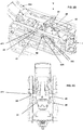
- the above-illustrated machine mainly comprises: a capsule-holder 1; an infusion head 2 apt to cooperated with the capsule-holder 1 for the extraction of the beverage; and moving means for the relative motion of the infusion head 2 and of the capsule-holder 1.
- the capsule-holder 1, the infusion head 2 and the just illustrated moving means can be considered a portion of an infusion group 101 of the machine.
- the above-mentioned moving means are suitable to determine a relative translational motion in a direction L of approaching/departing of the infusion head 2 to/from the capsule-holder 1.
- the capsule-holder 1 is stationary and the infusion head 2 moves in a direction L, the latter preferably horizontal.
- Such direction L even corresponds to that dispensing the infusion liquid and for this reason it can be defined even direction of infusion.
- it also corresponds to a longitudinal direction, possibly of symmetry, of the infusion group 101.
- proximal will designate each element nearest to the infusion head 2 along such direction L and “distal” will designate each element indeed farest from such head 2.
- the above-mentioned moving means even allow a relative shifting, still in direction L, of the capsule C with respect to the capsule-holder 1, allowing in particular the selective approaching/departing of the first one to/from the second one, and this by means of a pair of guiding devices which will be described shortly.
- the infusion group 101 even comprises a frame 102 which receives the capsule-holder 1 and the infusion head 2, the latter, as said, selectively mobile with respect to the frame 102 and to the capsule-holder 1 itself and apt to cooperate with the latter for the extraction of the beverage.
- the infusion head 2 bears one or more dispensing nozzles or channels 20 of an extraction fluid, typically water (one of such channels is partially visible in the above-mentioned figure).
- the head 2 is further in communication with relative fluid-feeding means at least partially external to the frame 102. Since the latter components are well known for a person skilled in the art on themselves, one will not further dwell upon the description thereof.
- the head 2 bears a plurality of boring teeth of the capsule, one thereof designated by way of example with 21.
- a sealing, preferably round gasket 22 is further provided, arranged like a crown or a ring around the boring teeth 21.
- the gasket 22 is mounted integral to such teeth 21 and fastened to a generally larger inner proximal gasket (the latter not visible in the figures).
- the overall configuration known on itself, is so that, at the beginning of the infusion, such more internal gasket deforms in a predetermined way in direction L due to the effect of the pressure induced by a pump feeding the dispensing channels 20. In this way, such inner gasket makes the gasket 22 and the teeth 21 to perform a calibrated distal shifting with respect to the remaining portion of the infusion head 2 guaranteeing the optimum perforation of the capsule and the sealing of the gasket 22 itself.
- the infusion head 2 further bears a pair of engagement elements 24, arranged bilaterally thereon and visible for example in figures 2B and 2C , the function thereof will be explained hereinafter.
- engagement elements 24 are shaped like a post or pin.
- elastic means - not represented in the figures - can be associated, arranged in several places and apt to connect the head 2 itself to the frame 102. Since even such arrangement of elastic means is known on itself, one will not further dwell upon the relative description.
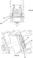
- FIG. 5A A preferred embodiment of the capsule-holder 1 is shown in figures 5A and 5B .
- the capsule-holder 1 defines an infusion chamber 10 suitable to receive the capsule indeed during the infusion and which thus implements a seat or receptacle for the capsule itself.
- the infusion chamber 10 substantially is shaped like a cup or however it has a suitable convex shape.
- the chamber 10 and the capsule-holder 1 have a substantially circular geometry. Still in the present example, the chamber 10 has a tapered, in particular substantially truncated conical shape, with larger base 111 arranged at the inlet of the infusion liquid, that is proximally, and smaller base 112 arranged on the opposite side, that is at the side dispensing the beverage and thus distally.
- the capsule-holder 1 at its own wall or side skirt 11 delimiting the infusion chamber 10, has a shaped projection, or tooth, 12 apt to engage a recess R of the capsule C shown in figure 4 .
- the tooth 12 implements engagement means of the capsule C apt to determine a predetermined, in case univocal positioning, of the capsule itself within the capsule-holder 1.
- the tooth 12 starts the engagement with a recess R of the capsule, by inducing the latter to rotate to implement a complete engagement of the tooth 12 in the recess R.
- the capsule C has a plurality of shaped recesses R, preferably six. The relative sizing between capsule and capsule-holder is so that, in any initial orientation of the capsule upon the insertion in the capsule-holder, there is a recess R engaging at least partially the tooth 12.
- both for the capsule C and for the capsule-holder 1 the position of the recesses R or of the tooth 12 determines even a variation in the cross section, and in particular a reduction thereof in the direction of infusion L, as already mentioned above.
- Embodiment variants can provide mutual engagement means between capsule-holder and capsule different from those considered herein, and in particular an inverted position of the number and type of projections and recesses between capsule and capsule-holder.
- the coupling between capsule and capsule-holder which brings the first one to rotate with respect to the second one substantially according to an axis parallel to L is based upon the engagement of respective tilted profiles or planes.
- the capsule C further has a projecting upper edge B suitable to allow to retain the capsule during the insertion and extraction phases, as it will be described in details hereinafter.
- the infusion group 101 further comprises at least a guiding device of a capsule C for inserting and extracting the latter into/from the capsule-holder 1.
- two guiding devices are advantageously provided, both represented in figure 1 and herein designated with 100 and 100'.
- the latter preferably are identical and arranged bilaterally with respect to the direction of infusion L.
- the device 100 will be described and it will be referred to, the same description for the device 100' being valid.
- the device 100 is in form of a monolithic body, in case implemented as one piece.
- the device 100 first of all comprises means for retaining the capsule during a relative motion between the latter and the capsule-holder 1.
- Such retaining means in turn comprises a first retaining element 31 and a second retaining element 32 of the edge B of the capsule C.
- each one of the elements 31 and 32 is configured like a guide or channel, wherein preferably the edge B of the capsule is retained between two substantially parallel walls.
- each element 31, 32 bears a longitudinal seat, respectively 311 and 321, extending in a direction V of engagement of the edge B of the capsule.
- Such direction V is substantially orthogonal to the of infusion L and, in the present example, substantially vertical for both the elements 31 and 32.
- the first retaining element 31 is apt to retain the capsule during a relative motion that carries the capsule to be infused to enter the infusion chamber 10
- the second retaining element 32 is configured so as to retain the capsule during a relative motion of extracting the used capsule from the infusion chamber 10, by allowing the ejection thereof by gravity from the group 101.
- the first retaining element 31 is configured in form of guide extending along the engagement direction V and bears terminal stop means 312 (visible in figure 1 only for the device 100').
- the configuration of the first element 31 is so that the edge B of the capsule engages the seat 311, slide within it according to the direction V and abuts on the terminal stop means 312.
- the latter is constituted in an edge arranged substantially orthogonal to the engagement direction V.
- the first element 31 comprises an invitation to the insertion 314.
- the first retaining element 31, at or near the terminal stop means 312, has a profile or lateral seat 313 substantially shaped like a squared "C" or a jaw, and in general with a shape allowing the release of the edge B when the element 31 is moved in a direction of departing from the capsule.
- the retaining element 31 Upwardly such seat 313, that is in a distal direction with respect to the abutment edge 312, the retaining element 31 bears a recess 313', preferably with arcuate and in particular circular profile.
- Such recess 313' extends in cross direction, that is substantially orthogonal both to the direction of infusion L and to the engagement direction V. It defines a communication between the seats or channels 311 and 321.
- the recess 313' allows an easy release of the capsule from the channel 311 in the capsule-holder 1 and it favours, in a subsequent phase after the infusion, to hook the capsule by the second retaining element 32.
- the configuration of the recess 313' allows avoiding interferences of the guiding device 100 with the capsule-holder 1 in said phases of insertion and extraction into/from the capsule-holder 1.
- the second retaining element 32 is configured in a shape substantially like a "L” or “C”. In particular, it bears an engagement edge or flange 322 (better visible in figure 1 for the device 100'), and in general a hooking element, suitable to "hook” and, in the present example, to drag the edge B of the capsule to allow the disengagement thereof from the capsule-holder 1 and a subsequent fall by gravity outside the infusion group 101.
- the first and the second element 31 and 32 has an oblong shape and extend according to the engagement direction V, which is indeed the direction of prevailing extension.
- the first element 31 is longer than the second element 32 along such direction to allow the insertion and guide of a "fresh" capsule in the position abutted onto the edge 312.
- the second element 32 indeed, is shorter and it extends parallelly to the first element 31 at the ending portion thereof, even to not interfere with other mechanisms of the infusion group 101, and in particular with the infusion head 2.
- the device 100 further comprises a pair of arms 41 and 42, which define mechanical control means apt to determine that the relative motion between capsule C and capsule-holder 1 is performed in coordinated way with the relative position between capsule-holder 1 and infusion head 2.
- the guiding device 100 that carries the capsule generally, is released from the infusion head 2; however, through such mechanical control means the device can be induced to move integrally to the head 2 in selected phases of an infusion cycle, as it will be illustrated in more details shortly.
- each arm 41, 42 is configured to engage a corresponding seat or guide 103 obtained in the frame 102 of the infusion group 101.
- the terminal end of the arm 42 distal with respect to the retaining elements 31 and 32 bears an engagement element 421, suitable to be slidingly coupled and/or guided in the seat or guide 103 on the frame 102.
- the arm 41 bears too, at the terminal distal end with respect to the retaining elements 31 and 32, an engagement element 411.
- Such element 411 of the arm 41 is apt to interact with a respective engagement element 24 of the head 2.
- the coupling between elements 411 and 24 is so as to allow a selective dragging in translation of the devices 100 and 100' by the head 2 during a return stroke after infusion.
- the first arm 41 further bears, in intermediate position, a cam profile 412, or equivalent means, suitable to establish a positive connection with a respective engagement element 24 of the infusion head 2. Still as it will be illustrated hereinafter by referring to the operating modes of the machine, such connection is so that the head 2 can induce each one of the devices 101 and 101' to rotate around an axis substantially parallel to the direction V and arranged at the profile 412, so as to approach/depart selectively the retaining elements 31 and 32 to/from the capsule.
- the devices 100 and 100' are then mounted on the machine, and in particular on the frame 102, so that they can slide, as said above, along the direction L and they can further rotate around respective axes substantially parallel to the direction V and substantially localized at the profiles 412.
- contrast means is provided suitable to brink the devices 100 and 100' back into the not rotated position shown in the herein considered figures 2B and 2C .
- the arms 41 and 42 extend according to mutually angled directions.
- the machine of the present example provides a lever or actuating arm 104 associated to a knuckle mechanism.
- the lever 104 is actuated in rotation (as designated schematically by the double arrow in figure 2B ) so as to make accessible the infusion group 101, and in particular the first retaining elements 31 of the devices 100 and 100'.
- the edge B of the capsule C can be then inserted in such elements 31 according to the engagement direction V, until abutting onto the edges 312.
- the infusion head 2 is in a retracted position, spaced apart from the capsule-holder 1.
- the actuating lever 104 is rotated again to close back onto the frame 102.
- Such motion of the lever 104 directly or by means of a control unit, controls the feeding of the infusion head 2 towards the capsule-holder 1.
- the actuation of the lever 104 can be manual or can be performed by means of suitable control means of the dispensing machine wherein the infusion group 101 is mounted.
- the overall configuration is so that, in this phase, the devices 100 and 100' do not move integrally to the infusion head 2, as the engagement elements 24 of the latter slide along the arms 41, by departing from the elements 411 along the direction L.
- the engagement elements 24 of the head 2 have met the cam profiles 412, while they continue to slide, they drag in translation the devices 100, 100'.
- the coupling between elements 24 and cam profiles 412 determines a rotation motion, and in particular a divarication motion, of the devices 100 and 100' (double arrows in figure 2D ).
- the retaining elements 31 wholly release the edge B of the capsule at an infusion position wherein the capsule C is inserted in the infusion chamber 10 of the capsule-holder 1 according to the modes already described above.
- the overall configuration is so that at this point the infusion head 2 is in abutment on the larger base 101 of the capsule-holder 1.
- the infusion head 2 adds hot liquid within the capsule C, performing the phase of extracting the beverage.
- the above-mentioned configuration with double circular sealing gasket, the most external thereof designated with 22, makes that the closing of the lever 104 has not to be as strong as to guarantee the pressure tightness, since in fact it is assigned to the deformation of the above-mentioned inner gasket of the infusion head 2. Furthermore, during the pressure release (typically guaranteed by a release electric valve) there is the outlet of the inner pressure of the capsule at the circular gasket 22 with release of coffee/water in a tray for collecting used capsules, thus avoiding the very boring dripping of coffee from the dispensing nozzle in the cup, typical of all the machines nowadays on sale.
- the head 2 starts its own return stroke in direction L.
- Such return stroke can be obtained by means of the action of the above-mentioned elastic means, which connects the head 2 to the frame 102.
- the engagement elements 24 disengage the profiles 412, by allowing a rotation of the retaining elements 32 towards the edge B of the capsule.
- the motion of inverse rotation performed by the guiding devices 100 and 100' after the interaction of the engagement elements 24 with the cam profiles 412 is guided indeed by the shape of such profiles. It is so that, once ended the rotation, the retaining elements 31 are arranged upwardly of the edge and the elements 32 engaged thereon.
- the recesses 313' favour to hook the capsule in the seats 321.
- the devices 100 and 100' start again to move integrally to the head 2 as the elements 24 of the latter have brought in abutment on the elements 411.
- the retaining elements 32 drag the capsule C outside the capsule-holder 1.
- the capsule falls by gravity outside the infusion group 101.
- An embodiment variant can provide that the capsule-holder is mounted on the infusion head and moves in a coordinated way therewith and that the guiding device(s) is/are stationary and arranged at the end of the infusion stroke.
- the above-mentioned engagement means 24 could be associated to the capsule-holder.
- the set of the invention is particularly suitable to be used with disposable and/or single-dose capsules, in principle it can be applied even to re-usable or multi-use and/or multi-use capsules.
Landscapes
- Engineering & Computer Science (AREA)
- Food Science & Technology (AREA)
- Mechanical Engineering (AREA)
- Apparatus For Making Beverages (AREA)
Claims (16)
- Machine pour distribuer des boissons infusées extraites à partir de capsules, en particulier du café, du thé, des tisanes et similaires, comprenant un groupe d'infusion (101), lequel groupe d'infusion (101) comprend :un support de capsule (1) qui définit une chambre d'infusion (10) ;une tête d'infusion (2) appropriée pour coopérer avec ledit support de capsule (1) pour l'extraction de la boisson ;un moyen de déplacement pour le mouvement relatif d'une capsule (C) par rapport audit support de capsule (1), approprié pour déterminer un mouvement de translation relatif dans une direction d'infusion (L) qui est une direction d'approche/éloignement de la capsule vers/de ladite chambre d'infusion (10) ; etun dispositif de guidage (100), de préférence deux dispositifs de guidage (100, 100') agencés de manière bilatérale par rapport à la direction d'infusion (L),lequel dispositif de guidage (100) comprend :un moyen de retenue (31, 32) de la capsule pendant ledit mouvement relatif entre ladite capsule et le support de capsule (1), comprenant au moins un premier (31) et un second élément (32) pour retenir un bord en saillie périphérique (B) de la capsule,dans laquelle ledit premier élément de retenue (31) est configuré pour retenir la capsule pendant un mouvement relatif qui amène la capsule à infuser à entrer dans la chambre d'infusion (10),et ledit second élément de retenue (32) est configuré afin de retenir la capsule pendant un mouvement relatif d'extraction de la capsule utilisée, à partir de la chambre d'infusion (10) pour permettre son éjection par gravité de la machine ; etun moyen de commande mécanique (41, 42) approprié pour déterminer que le mouvement relatif entre la capsule et le support de capsule (1) est réalisé d'une manière coordonnée avec la position relative entre le support de capsule (1) et la tête d'infusion (2),dans lequel ledit moyen de commande mécanique comprend à son tour :un ou une paire de bras (41, 42), chacun configuré pour être couplé de manière coulissante avec un bâti (102) de la machine ;un moyen de mise en prise (412) obtenu sur ledit bras ou l'un desdits bras (41), approprié pour se coupler avec un profil correspondant de la machine (24), ledit couplage provoquant, à l'usage une déviation du dispositif (100) par rapport à la tête d'infusion (2) ; caractérisé en ce que ledit moyens de commande mécanique comprend en outre :un élément de mise en prise (411) obtenu sur ledit bras ou sur l'un desdits bras (41), approprié pour se coupler avec un élément de mise en prise (24) respectif de la machine afin de permettre une trainée sélective de translation du dispositif (100) pendant une course de retour, après l'infusion.
- Machine selon la revendication précédente, dont la configuration globale est telle que, à l'usage, ladite direction d'infusion (L) est une direction sensiblement horizontale et ladite direction de mise en prise (V) est une direction sensiblement verticale.
- Machine selon la revendication 1 ou 2, dans laquelle ladite tête d'infusion (2) et ledit moyen de commande mécanique (4) dudit dispositif de guidage (100) sont configurés afin de déterminer un éloignement, en particulier une déviation et de préférence une rotation, dudit (desdits) premier(s) élément(s) de support (31) par rapport à la capsule (C) au niveau de ou à proximité d'une position de butée mutuelle de ladite tête (2) et dudit support de capsule (1) qui correspond à l'infusion.
- Machine selon l'une quelconque des revendications 1 à 3, dans laquelle ladite tête d'infusion (2) et/ou ledit support de capsule (1) comprennent un moyen de mise en prise (24) dudit moyen de commande mécanique (41) dudit (desdits) dispositif(s) (100), la configuration globale étant telle que le couplage entre ledit moyen de mise en prise (24) et ledit moyen de commande mécanique (41) détermine sélectivement une trainée de translation et/ou une rotation dudit (desdits) dispositif(s) (100).
- Machine selon l'une quelconque des revendications 1 à 4, dans laquelle ledit support de capsule (1) a, au niveau d'une paroi latérale (11) définissant ladite chambre d'infusion (10), un moyen de mise en prise de la capsule (12) approprié pour déterminer un positionnement prédéterminé de la capsule à l'intérieur du support de capsule (1) en induisant un mouvement de rotation de la capsule par rapport au support de capsule (1), de préférence selon un axe sensiblement parallèle à ladite direction d'infusion (L).
- Machine selon la revendication précédente, dans laquelle ledit moyen de mise en prise de la capsule (12) comprend un ou plusieurs profils ou plans inclinés.
- Machine selon la revendication 5 ou 6, dans laquelle ledit moyen de mise en prise de capsule comprend au moins une saillie ou dent (12) obtenue sur ladite paroi latérale (11) et appropriée pour mettre en prise un évidement (R) respectif de la capsule.
- Machine selon l'une quelconque des revendications précédentes, dans laquelle un ou chacun parmi ledit premier (31) et ledit second (32) élément de retenue a un siège d'insertion/retenue oblong (311, 321) du bord (B) de la capsule, lequel siège s'étend, à l'usage, selon une direction de mise en prise (V) sensiblement perpendiculaire à la direction d'infusion (L).
- Machine selon l'une quelconque des revendications précédentes, dans laquelle un ou chacun parmi ledit premier (31) et ledit second (32) élément de retenue est configuré sous la forme d'un guide ou d'un canal s'étendant le long d'une direction de mise en prise (V), de préférence de sorte que le bord (B) de la capsule est guidé/retenu entre deux parois sensiblement parallèles.
- Machine selon l'une quelconque des revendications précédentes, dans laquelle ledit premier élément de retenue (31) à un moyen de butée terminal (312), de sorte que, à l'usage, le bord (B) de la capsule peut mettre en prise ledit premier élément de retenue (31), coulisser à l'intérieur de ce dernier et venir en butée sur ledit moyen de butée terminal (312).
- Machine selon l'une quelconque des revendications précédentes, dans laquelle ledit premier élément de retenue (31) a, au niveau de ou à proximité d'une extrémité de retenue terminale, une forme de mâchoire ou en forme de « C » sensiblement carré, capable de permettre la libération du bord (B) de la capsule lorsque l'élément de retenue (31) s'éloigne de la capsule.
- Machine selon l'une quelconque des revendications précédentes, dans laquelle ledit second élément de retenue (32) est configuré sensiblement sous la forme de « L », « C » ou d'un crochet afin de permettre le dégagement de la capsule du support de capsule (1) et la chute consécutive par gravité de la capsule.
- Machine selon l'une quelconque des revendications précédentes, dans laquelle les bras de ladite paire (41, 42) s'étendent dans des directions mutuellement coudées.
- Machine selon l'une quelconque des revendications précédentes, dans laquelle ledit dispositif de guidage (100) est configuré pour être, à l'usage, couplé de manière coulissante et rotative avec un bâti (102) de la machine.
- Machine selon l'une quelconque des revendications précédentes, dans laquelle ledit dispositif de guidage (100) se présente sous la forme d'un corps monolithique.
- Machine selon l'une quelconque des revendications précédentes, dans laquelle ledit moyen de mise en prise obtenu sur ledit bras ou l'un desdits bras (41) est un profil de mise en prise de came (412).
Applications Claiming Priority (2)
| Application Number | Priority Date | Filing Date | Title |
|---|---|---|---|
| ITRM20130593 ITRM20130593A1 (it) | 2013-10-25 | 2013-10-25 | Macchina per erogazione di bevande |
| PCT/IB2014/065469 WO2015059621A1 (fr) | 2013-10-25 | 2014-10-20 | Machine pour distribuer des boissons |
Publications (2)
| Publication Number | Publication Date |
|---|---|
| EP3060087A1 EP3060087A1 (fr) | 2016-08-31 |
| EP3060087B1 true EP3060087B1 (fr) | 2017-07-19 |
Family
ID=49683980
Family Applications (1)
| Application Number | Title | Priority Date | Filing Date |
|---|---|---|---|
| EP14802181.9A Not-in-force EP3060087B1 (fr) | 2013-10-25 | 2014-10-20 | Machine pour distribuer des boissons |
Country Status (5)
| Country | Link |
|---|---|
| US (1) | US10188236B2 (fr) |
| EP (1) | EP3060087B1 (fr) |
| CN (1) | CN105764388A (fr) |
| IT (1) | ITRM20130593A1 (fr) |
| WO (1) | WO2015059621A1 (fr) |
Families Citing this family (5)
| Publication number | Priority date | Publication date | Assignee | Title |
|---|---|---|---|---|
| US20170251863A1 (en) * | 2016-03-03 | 2017-09-07 | Juicero, Inc. | Angled juicing system |
| CA3117932A1 (fr) | 2018-10-30 | 2020-05-07 | Keurig Green Mountain, Inc. | Machine de preparation de boissons dote d'un agencement d'entree |
| CN110250914B (zh) * | 2019-07-04 | 2023-12-19 | 深圳市西啡科技有限公司 | 饮料冲泡结构与饮料机 |
| CN110279297B (zh) * | 2019-07-04 | 2024-02-09 | 深圳市西啡科技有限公司 | 冲泡组件与饮料机 |
| IT202100031661A1 (it) * | 2021-12-17 | 2023-06-17 | Gise Caffe’ S R L | Macchina per la preparazione e l'estrazione di una bevanda calda |
Family Cites Families (16)
| Publication number | Priority date | Publication date | Assignee | Title |
|---|---|---|---|---|
| ITMI20050854A1 (it) * | 2005-05-12 | 2006-11-13 | Perfect Steam Appliances Ltd | Gruppo di infusione per macchine per la preparazione di bevande |
| PT1859712E (pt) * | 2006-05-24 | 2009-02-02 | Nestec Sa | Módulo de perfuração de cápsulas |
| ITFI20060194A1 (it) * | 2006-08-04 | 2008-02-05 | Saeco Ipr Ltd | Dispositivo di infusione per la preparazione di bevande da capsule monodose |
| WO2009084059A1 (fr) * | 2008-01-03 | 2009-07-09 | Essence-Sbt Sa | Système destiné à acheminer des boissons d'infusion et capsule d'infusion |
| DK2368466T3 (en) * | 2010-03-24 | 2014-03-03 | Delica Ag | A device for preparing a beverage |
| US20150125586A1 (en) * | 2010-05-03 | 2015-05-07 | Apiqe | Beverage system with flavor pod dispenser |
| CN103153143B (zh) * | 2010-10-08 | 2016-08-24 | 皇家飞利浦电子股份有限公司 | 具有水平运动的泡制单元 |
| ITMI20110877A1 (it) * | 2011-05-18 | 2012-11-19 | Swiss Caffe Asia Ltd | Gruppo infusore, particolarmente per capsule e/o cialde per l'ottenimento di bevande infuse e simili. |
| EP2543290A1 (fr) * | 2011-07-08 | 2013-01-09 | Koninklijke Philips Electronics N.V. | Unité de brassage dotée d'un chauffage pour l'eau |
| PT2747611T (pt) * | 2011-08-25 | 2017-12-26 | Nestec Sa | Câmara de cartucho de sistema de extração |
| EP2747610B1 (fr) * | 2011-08-25 | 2018-02-28 | Nestec S.A. | Système de suppression de cartouche |
| ITTO20110819A1 (it) * | 2011-09-14 | 2013-03-15 | Lavazza Luigi Spa | Dispositivo per la preparazione di bevande e relativo procedimento |
| JP6086929B2 (ja) * | 2012-01-25 | 2017-03-01 | キュー・ビー・オー・コーヒー・ゲゼルシャフト・ミット・ベシュレンクテル・ハフツングQbo Coffee Gmbh | ブリューイングモジュール |
| US9795245B2 (en) * | 2012-03-14 | 2017-10-24 | Hamilton Beach Brands, Inc. | Kitchen appliance for preparing a beverage and method of operating same |
| ITTO20120503A1 (it) * | 2012-06-08 | 2013-12-09 | Lavazza Luigi Spa | Gruppo erogatore per macchine per la preparazione di bevande tramite capsule |
| ITTO20120659A1 (it) * | 2012-07-26 | 2014-01-27 | Lavazza Luigi Spa | Gruppo erogatore per macchine per la preparazione di bevande tramite capsule |
-
2013
- 2013-10-25 IT ITRM20130593 patent/ITRM20130593A1/it unknown
-
2014
- 2014-10-20 US US15/032,504 patent/US10188236B2/en not_active Expired - Fee Related
- 2014-10-20 WO PCT/IB2014/065469 patent/WO2015059621A1/fr not_active Ceased
- 2014-10-20 CN CN201480064457.7A patent/CN105764388A/zh active Pending
- 2014-10-20 EP EP14802181.9A patent/EP3060087B1/fr not_active Not-in-force
Non-Patent Citations (1)
| Title |
|---|
| None * |
Also Published As
| Publication number | Publication date |
|---|---|
| US10188236B2 (en) | 2019-01-29 |
| US20160309945A1 (en) | 2016-10-27 |
| CN105764388A (zh) | 2016-07-13 |
| WO2015059621A1 (fr) | 2015-04-30 |
| ITRM20130593A1 (it) | 2015-04-26 |
| EP3060087A1 (fr) | 2016-08-31 |
Similar Documents
| Publication | Publication Date | Title |
|---|---|---|
| EP2877067B1 (fr) | Ensemble de distribution pour machines pour la préparation de boissons à l'aide de capsules | |
| EP3060087B1 (fr) | Machine pour distribuer des boissons | |
| EP2717749B1 (fr) | Ensemble de distribution pour machines de préparation de produits liquides utilisant des cartouches | |
| EP2717748B1 (fr) | Ensemble de distribution pour machines permettant de préparer des produits liquides au moyen de cartouches | |
| EP2571405B1 (fr) | Système de fabrication de boisson par utilisation de capsules | |
| EP2827752B1 (fr) | Ensemble de distribution pour machines pour la préparation de produits liquides par l'intermédiaire de cartouches | |
| WO2014174462A1 (fr) | Machine pour distribuer des boissons | |
| AU2012265877A1 (en) | Delivery assembly for machines for preparing liquid products via cartridges | |
| CN101897545A (zh) | 饮料酿造机构及具有该酿造机构的饮料制作装置 | |
| EP2378933B1 (fr) | Ensemble d'infusion pour une machine destinée à la préparation de boissons | |
| EP2509475B1 (fr) | Machine pour la distribution d'infusions | |
| HK1227269B (en) | Machine for dispensing beverages | |
| HK1227269A1 (en) | Machine for dispensing beverages | |
| CN201743501U (zh) | 饮料酿造机构及具有该酿造机构的饮料制作装置 | |
| EP3125729B1 (fr) | Unité d'infusion | |
| US20150101488A1 (en) | Machine for preparing beverages | |
| HK1177669B (en) | Machine for dispensing infusions | |
| IT201700020604A1 (it) | Macchina per la preparazione di bevande che utilizza cariche preconfezionate adatte a tale preparazione |
Legal Events
| Date | Code | Title | Description |
|---|---|---|---|
| PUAI | Public reference made under article 153(3) epc to a published international application that has entered the european phase |
Free format text: ORIGINAL CODE: 0009012 |
|
| 17P | Request for examination filed |
Effective date: 20160503 |
|
| AK | Designated contracting states |
Kind code of ref document: A1 Designated state(s): AL AT BE BG CH CY CZ DE DK EE ES FI FR GB GR HR HU IE IS IT LI LT LU LV MC MK MT NL NO PL PT RO RS SE SI SK SM TR |
|
| AX | Request for extension of the european patent |
Extension state: BA ME |
|
| DAX | Request for extension of the european patent (deleted) | ||
| GRAP | Despatch of communication of intention to grant a patent |
Free format text: ORIGINAL CODE: EPIDOSNIGR1 |
|
| INTG | Intention to grant announced |
Effective date: 20170221 |
|
| GRAS | Grant fee paid |
Free format text: ORIGINAL CODE: EPIDOSNIGR3 |
|
| GRAA | (expected) grant |
Free format text: ORIGINAL CODE: 0009210 |
|
| AK | Designated contracting states |
Kind code of ref document: B1 Designated state(s): AL AT BE BG CH CY CZ DE DK EE ES FI FR GB GR HR HU IE IS IT LI LT LU LV MC MK MT NL NO PL PT RO RS SE SI SK SM TR |
|
| REG | Reference to a national code |
Ref country code: GB Ref legal event code: FG4D |
|
| REG | Reference to a national code |
Ref country code: CH Ref legal event code: EP |
|
| REG | Reference to a national code |
Ref country code: IE Ref legal event code: FG4D |
|
| REG | Reference to a national code |
Ref country code: AT Ref legal event code: REF Ref document number: 909539 Country of ref document: AT Kind code of ref document: T Effective date: 20170815 |
|
| REG | Reference to a national code |
Ref country code: DE Ref legal event code: R096 Ref document number: 602014012104 Country of ref document: DE |
|
| REG | Reference to a national code |
Ref country code: HK Ref legal event code: DE Ref document number: 1227269 Country of ref document: HK |
|
| REG | Reference to a national code |
Ref country code: FR Ref legal event code: PLFP Year of fee payment: 4 |
|
| REG | Reference to a national code |
Ref country code: CH Ref legal event code: NV Representative=s name: PATENTANWAELTE SCHAAD, BALASS, MENZL AND PARTN, CH |
|
| REG | Reference to a national code |
Ref country code: NL Ref legal event code: MP Effective date: 20170719 |
|
| REG | Reference to a national code |
Ref country code: LT Ref legal event code: MG4D |
|
| PG25 | Lapsed in a contracting state [announced via postgrant information from national office to epo] |
Ref country code: NO Free format text: LAPSE BECAUSE OF FAILURE TO SUBMIT A TRANSLATION OF THE DESCRIPTION OR TO PAY THE FEE WITHIN THE PRESCRIBED TIME-LIMIT Effective date: 20171019 Ref country code: NL Free format text: LAPSE BECAUSE OF FAILURE TO SUBMIT A TRANSLATION OF THE DESCRIPTION OR TO PAY THE FEE WITHIN THE PRESCRIBED TIME-LIMIT Effective date: 20170719 Ref country code: LT Free format text: LAPSE BECAUSE OF FAILURE TO SUBMIT A TRANSLATION OF THE DESCRIPTION OR TO PAY THE FEE WITHIN THE PRESCRIBED TIME-LIMIT Effective date: 20170719 Ref country code: HR Free format text: LAPSE BECAUSE OF FAILURE TO SUBMIT A TRANSLATION OF THE DESCRIPTION OR TO PAY THE FEE WITHIN THE PRESCRIBED TIME-LIMIT Effective date: 20170719 Ref country code: SE Free format text: LAPSE BECAUSE OF FAILURE TO SUBMIT A TRANSLATION OF THE DESCRIPTION OR TO PAY THE FEE WITHIN THE PRESCRIBED TIME-LIMIT Effective date: 20170719 Ref country code: FI Free format text: LAPSE BECAUSE OF FAILURE TO SUBMIT A TRANSLATION OF THE DESCRIPTION OR TO PAY THE FEE WITHIN THE PRESCRIBED TIME-LIMIT Effective date: 20170719 |
|
| PGFP | Annual fee paid to national office [announced via postgrant information from national office to epo] |
Ref country code: FR Payment date: 20171024 Year of fee payment: 4 Ref country code: DE Payment date: 20171019 Year of fee payment: 4 |
|
| PG25 | Lapsed in a contracting state [announced via postgrant information from national office to epo] |
Ref country code: RS Free format text: LAPSE BECAUSE OF FAILURE TO SUBMIT A TRANSLATION OF THE DESCRIPTION OR TO PAY THE FEE WITHIN THE PRESCRIBED TIME-LIMIT Effective date: 20170719 Ref country code: BG Free format text: LAPSE BECAUSE OF FAILURE TO SUBMIT A TRANSLATION OF THE DESCRIPTION OR TO PAY THE FEE WITHIN THE PRESCRIBED TIME-LIMIT Effective date: 20171019 Ref country code: PL Free format text: LAPSE BECAUSE OF FAILURE TO SUBMIT A TRANSLATION OF THE DESCRIPTION OR TO PAY THE FEE WITHIN THE PRESCRIBED TIME-LIMIT Effective date: 20170719 Ref country code: LV Free format text: LAPSE BECAUSE OF FAILURE TO SUBMIT A TRANSLATION OF THE DESCRIPTION OR TO PAY THE FEE WITHIN THE PRESCRIBED TIME-LIMIT Effective date: 20170719 Ref country code: GR Free format text: LAPSE BECAUSE OF FAILURE TO SUBMIT A TRANSLATION OF THE DESCRIPTION OR TO PAY THE FEE WITHIN THE PRESCRIBED TIME-LIMIT Effective date: 20171020 Ref country code: ES Free format text: LAPSE BECAUSE OF FAILURE TO SUBMIT A TRANSLATION OF THE DESCRIPTION OR TO PAY THE FEE WITHIN THE PRESCRIBED TIME-LIMIT Effective date: 20170719 Ref country code: IS Free format text: LAPSE BECAUSE OF FAILURE TO SUBMIT A TRANSLATION OF THE DESCRIPTION OR TO PAY THE FEE WITHIN THE PRESCRIBED TIME-LIMIT Effective date: 20171119 |
|
| PGFP | Annual fee paid to national office [announced via postgrant information from national office to epo] |
Ref country code: LU Payment date: 20170821 Year of fee payment: 12 |
|
| REG | Reference to a national code |
Ref country code: DE Ref legal event code: R097 Ref document number: 602014012104 Country of ref document: DE |
|
| PG25 | Lapsed in a contracting state [announced via postgrant information from national office to epo] |
Ref country code: RO Free format text: LAPSE BECAUSE OF FAILURE TO SUBMIT A TRANSLATION OF THE DESCRIPTION OR TO PAY THE FEE WITHIN THE PRESCRIBED TIME-LIMIT Effective date: 20170719 Ref country code: DK Free format text: LAPSE BECAUSE OF FAILURE TO SUBMIT A TRANSLATION OF THE DESCRIPTION OR TO PAY THE FEE WITHIN THE PRESCRIBED TIME-LIMIT Effective date: 20170719 Ref country code: CZ Free format text: LAPSE BECAUSE OF FAILURE TO SUBMIT A TRANSLATION OF THE DESCRIPTION OR TO PAY THE FEE WITHIN THE PRESCRIBED TIME-LIMIT Effective date: 20170719 |
|
| REG | Reference to a national code |
Ref country code: HK Ref legal event code: GR Ref document number: 1227269 Country of ref document: HK |
|
| PLBE | No opposition filed within time limit |
Free format text: ORIGINAL CODE: 0009261 |
|
| STAA | Information on the status of an ep patent application or granted ep patent |
Free format text: STATUS: NO OPPOSITION FILED WITHIN TIME LIMIT |
|
| PG25 | Lapsed in a contracting state [announced via postgrant information from national office to epo] |
Ref country code: SK Free format text: LAPSE BECAUSE OF FAILURE TO SUBMIT A TRANSLATION OF THE DESCRIPTION OR TO PAY THE FEE WITHIN THE PRESCRIBED TIME-LIMIT Effective date: 20170719 Ref country code: SM Free format text: LAPSE BECAUSE OF FAILURE TO SUBMIT A TRANSLATION OF THE DESCRIPTION OR TO PAY THE FEE WITHIN THE PRESCRIBED TIME-LIMIT Effective date: 20170719 Ref country code: EE Free format text: LAPSE BECAUSE OF FAILURE TO SUBMIT A TRANSLATION OF THE DESCRIPTION OR TO PAY THE FEE WITHIN THE PRESCRIBED TIME-LIMIT Effective date: 20170719 Ref country code: MC Free format text: LAPSE BECAUSE OF FAILURE TO SUBMIT A TRANSLATION OF THE DESCRIPTION OR TO PAY THE FEE WITHIN THE PRESCRIBED TIME-LIMIT Effective date: 20170719 |
|
| 26N | No opposition filed |
Effective date: 20180420 |
|
| REG | Reference to a national code |
Ref country code: IE Ref legal event code: MM4A |
|
| PG25 | Lapsed in a contracting state [announced via postgrant information from national office to epo] |
Ref country code: LU Free format text: LAPSE BECAUSE OF NON-PAYMENT OF DUE FEES Effective date: 20171020 |
|
| REG | Reference to a national code |
Ref country code: BE Ref legal event code: MM Effective date: 20171031 |
|
| PG25 | Lapsed in a contracting state [announced via postgrant information from national office to epo] |
Ref country code: SI Free format text: LAPSE BECAUSE OF FAILURE TO SUBMIT A TRANSLATION OF THE DESCRIPTION OR TO PAY THE FEE WITHIN THE PRESCRIBED TIME-LIMIT Effective date: 20170719 Ref country code: BE Free format text: LAPSE BECAUSE OF NON-PAYMENT OF DUE FEES Effective date: 20171031 |
|
| PG25 | Lapsed in a contracting state [announced via postgrant information from national office to epo] |
Ref country code: MT Free format text: LAPSE BECAUSE OF NON-PAYMENT OF DUE FEES Effective date: 20171020 |
|
| PG25 | Lapsed in a contracting state [announced via postgrant information from national office to epo] |
Ref country code: IE Free format text: LAPSE BECAUSE OF NON-PAYMENT OF DUE FEES Effective date: 20171020 |
|
| REG | Reference to a national code |
Ref country code: AT Ref legal event code: UEP Ref document number: 909539 Country of ref document: AT Kind code of ref document: T Effective date: 20170719 |
|
| REG | Reference to a national code |
Ref country code: DE Ref legal event code: R119 Ref document number: 602014012104 Country of ref document: DE |
|
| REG | Reference to a national code |
Ref country code: CH Ref legal event code: PL |
|
| GBPC | Gb: european patent ceased through non-payment of renewal fee |
Effective date: 20181020 |
|
| PG25 | Lapsed in a contracting state [announced via postgrant information from national office to epo] |
Ref country code: HU Free format text: LAPSE BECAUSE OF FAILURE TO SUBMIT A TRANSLATION OF THE DESCRIPTION OR TO PAY THE FEE WITHIN THE PRESCRIBED TIME-LIMIT; INVALID AB INITIO Effective date: 20141020 |
|
| PG25 | Lapsed in a contracting state [announced via postgrant information from national office to epo] |
Ref country code: DE Free format text: LAPSE BECAUSE OF NON-PAYMENT OF DUE FEES Effective date: 20190501 |
|
| PG25 | Lapsed in a contracting state [announced via postgrant information from national office to epo] |
Ref country code: FR Free format text: LAPSE BECAUSE OF NON-PAYMENT OF DUE FEES Effective date: 20181031 Ref country code: LI Free format text: LAPSE BECAUSE OF NON-PAYMENT OF DUE FEES Effective date: 20181031 Ref country code: CH Free format text: LAPSE BECAUSE OF NON-PAYMENT OF DUE FEES Effective date: 20181031 |
|
| PG25 | Lapsed in a contracting state [announced via postgrant information from national office to epo] |
Ref country code: CY Free format text: LAPSE BECAUSE OF FAILURE TO SUBMIT A TRANSLATION OF THE DESCRIPTION OR TO PAY THE FEE WITHIN THE PRESCRIBED TIME-LIMIT Effective date: 20170719 Ref country code: GB Free format text: LAPSE BECAUSE OF NON-PAYMENT OF DUE FEES Effective date: 20181020 |
|
| PG25 | Lapsed in a contracting state [announced via postgrant information from national office to epo] |
Ref country code: MK Free format text: LAPSE BECAUSE OF FAILURE TO SUBMIT A TRANSLATION OF THE DESCRIPTION OR TO PAY THE FEE WITHIN THE PRESCRIBED TIME-LIMIT Effective date: 20170719 |
|
| PG25 | Lapsed in a contracting state [announced via postgrant information from national office to epo] |
Ref country code: TR Free format text: LAPSE BECAUSE OF FAILURE TO SUBMIT A TRANSLATION OF THE DESCRIPTION OR TO PAY THE FEE WITHIN THE PRESCRIBED TIME-LIMIT Effective date: 20170719 |
|
| PG25 | Lapsed in a contracting state [announced via postgrant information from national office to epo] |
Ref country code: PT Free format text: LAPSE BECAUSE OF FAILURE TO SUBMIT A TRANSLATION OF THE DESCRIPTION OR TO PAY THE FEE WITHIN THE PRESCRIBED TIME-LIMIT Effective date: 20170719 |
|
| PG25 | Lapsed in a contracting state [announced via postgrant information from national office to epo] |
Ref country code: AL Free format text: LAPSE BECAUSE OF FAILURE TO SUBMIT A TRANSLATION OF THE DESCRIPTION OR TO PAY THE FEE WITHIN THE PRESCRIBED TIME-LIMIT Effective date: 20170719 |
|
| PGFP | Annual fee paid to national office [announced via postgrant information from national office to epo] |
Ref country code: IT Payment date: 20210817 Year of fee payment: 8 |
|
| PGFP | Annual fee paid to national office [announced via postgrant information from national office to epo] |
Ref country code: AT Payment date: 20211021 Year of fee payment: 8 |
|
| REG | Reference to a national code |
Ref country code: AT Ref legal event code: MM01 Ref document number: 909539 Country of ref document: AT Kind code of ref document: T Effective date: 20221020 |
|
| PG25 | Lapsed in a contracting state [announced via postgrant information from national office to epo] |
Ref country code: AT Free format text: LAPSE BECAUSE OF NON-PAYMENT OF DUE FEES Effective date: 20221020 |
|
| PG25 | Lapsed in a contracting state [announced via postgrant information from national office to epo] |
Ref country code: IT Free format text: LAPSE BECAUSE OF NON-PAYMENT OF DUE FEES Effective date: 20221020 |