EP3060427B1 - Système d'alimentation en air pour un siège de véhicule et procédé pour fonctionnement du système d'alimentation en air - Google Patents
Système d'alimentation en air pour un siège de véhicule et procédé pour fonctionnement du système d'alimentation en air Download PDFInfo
- Publication number
- EP3060427B1 EP3060427B1 EP14786212.2A EP14786212A EP3060427B1 EP 3060427 B1 EP3060427 B1 EP 3060427B1 EP 14786212 A EP14786212 A EP 14786212A EP 3060427 B1 EP3060427 B1 EP 3060427B1
- Authority
- EP
- European Patent Office
- Prior art keywords
- fan
- supply device
- air
- control unit
- fan speed
- Prior art date
- Legal status (The legal status is an assumption and is not a legal conclusion. Google has not performed a legal analysis and makes no representation as to the accuracy of the status listed.)
- Active
Links
Images
Classifications
-
- B—PERFORMING OPERATIONS; TRANSPORTING
- B60—VEHICLES IN GENERAL
- B60N—SEATS SPECIALLY ADAPTED FOR VEHICLES; VEHICLE PASSENGER ACCOMMODATION NOT OTHERWISE PROVIDED FOR
- B60N2/00—Seats specially adapted for vehicles; Arrangement or mounting of seats in vehicles
- B60N2/56—Heating or ventilating devices
- B60N2/5607—Heating or ventilating devices characterised by convection
- B60N2/5621—Heating or ventilating devices characterised by convection by air
- B60N2/5671—Heating or ventilating devices characterised by convection by air forming a windbreak, e.g. warm air blown on the neck of the passenger of an open vehicle
-
- B—PERFORMING OPERATIONS; TRANSPORTING
- B60—VEHICLES IN GENERAL
- B60N—SEATS SPECIALLY ADAPTED FOR VEHICLES; VEHICLE PASSENGER ACCOMMODATION NOT OTHERWISE PROVIDED FOR
- B60N2/00—Seats specially adapted for vehicles; Arrangement or mounting of seats in vehicles
- B60N2/56—Heating or ventilating devices
- B60N2/5607—Heating or ventilating devices characterised by convection
- B60N2/5621—Heating or ventilating devices characterised by convection by air
-
- B—PERFORMING OPERATIONS; TRANSPORTING
- B60—VEHICLES IN GENERAL
- B60N—SEATS SPECIALLY ADAPTED FOR VEHICLES; VEHICLE PASSENGER ACCOMMODATION NOT OTHERWISE PROVIDED FOR
- B60N2/00—Seats specially adapted for vehicles; Arrangement or mounting of seats in vehicles
- B60N2/56—Heating or ventilating devices
- B60N2/5678—Heating or ventilating devices characterised by electrical systems
- B60N2/5685—Resistance
Definitions
- the invention relates to a vehicle seat according to the preamble of claim 1, as well as a method for operating a correspondingly configured air supply device.
- an air supply device for a vehicle seat according to the preamble of claim 1 with an air outlet opening provided in the upper area of the vehicle seat, via which the head, shoulder and neck area of the seat occupant can be exposed to an air flow, is already known, the air flow through a control unit Control or regulation of a fan speed of a blower is adjustable and can be heated via a heating element, and the control unit is supplied with at least one switch-on signal for switching on the air supply device and a temperature signal from a temperature sensor that provides information about the interior temperature.
- preconditioning of the heating element is initiated before the air supply device is switched on as soon as the vehicle is unlocked and / or opened and at the same time the outside temperature and / or inside temperature falls below a threshold value previously stored in a memory device.
- Such an air supply device or a corresponding operation of the air supply device leads to the fact that the outflowing air is already at a pleasant temperature when the air supply device is switched on, but this is associated with a not inconsiderable load on the vehicle's electrical system and correspondingly high energy consumption even before the vehicle is operated .
- An air supply device for a vehicle seat designed for the neck area is also known, the control device of the air supply device regulating the fan speed of the blower in response to the outside temperature and the driving speed.
- the object of the invention is now to provide a vehicle seat and a corresponding method for operating an air supply device for a vehicle seat, by means of which the driver experiences a comfortable temperature of the head, shoulder and neck area in an energy-efficient manner when the air supply device is switched on.
- the vehicle seat has an air outflow opening provided in the upper area of the vehicle seat, via which the head, shoulder and neck area of the seat occupant can be subjected to an air flow.
- the air flow is by means of a Control unit adjustable by controlling or regulating a fan speed of a blower and can be heated via a controllable heating element.
- the basic idea of the invention is, from an energy-efficient point of view, to activate the air supply device or the heating element and the fan in principle only when a switch-on signal for switching on the air supply device is present.
- a switch-on signal is present when a vehicle occupant operates an operating element provided for activating the air supply device.
- a switch-on signal can also be generated on the basis of an automatic activation of the air supply device, for example when the vehicle top is opened and if a further condition is present, and sent to the control unit or generated there.
- the invention provides that the control unit is additionally supplied with a temperature signal that provides information about the interior temperature, and that the control unit switches on the heating element and the fan in response to the switch-on signal and at least controls the fan as a function of the interior temperature.
- the control unit is designed in such a way that, in response to a switch-on signal, it causes the fan to be operated only at a predetermined low minimum fan speed if the temperature signal indicates that the interior temperature is lower than a predetermined temperature threshold value.
- both the minimum fan speed and the temperature threshold value can be predefined in a fixed manner or variably as a function of predefined parameter values and stored in a corresponding memory unit.
- a temperature of approx. 10 ° C can be specified for this, for example.
- the minimum fan speed can be, for example, a value between 5% and 30% of the maximum fan speed.
- control unit causes the fan to be operated only at the low minimum fan speed when the air supply device is switched on due to a low interior temperature
- the control unit can then, in an advantageous development, cause the fan speed to increase when the temperature signal indicates that the interior temperature is no longer lower than the specified temperature threshold.
- control unit can also cause the fan speed of the fan to be increased (regardless of the interior temperature) if the fan has already been operated at the minimum fan speed for more than a predetermined period of time.
- the two above-mentioned change conditions can also be combined in such a way that the control unit then causes the fan operated at the minimum fan speed to be operated at a higher fan speed when the temperature signal indicates that the interior is no longer smaller than the
- the predetermined temperature threshold value is, regardless of the interior temperature, at the latest, however, when the fan has been operated at the minimum fan speed for more than a predetermined time interval.
- the fan speed is increased as soon as the first of the two conditions (temperature threshold value exceeded or time lapse) is met.
- the fan speed can be increased to a uniformly predetermined target speed when increasing due to the increased interior temperature or due to the expiration of the timer is generally higher than the minimum speed.
- the air supply device can, for example, be operated in different power levels in the same way as a seat heater, if the fan speed is increased, the blower can be operated at a power level fan speed that is dependent on the requested power level of the air supply device.
- the temperature threshold value and / or the minimum fan speed can also be specified as a function of the requested power level of the air supply unit.
- control unit also causes the temperature signal to indicate that the interior temperature is not less than a specified temperature threshold value, even if the switch-on signal is already present the fan is operated directly with a power stage fan speed which is dependent on a requested power level of the air supply device and which is greater than a predetermined minimum fan speed.
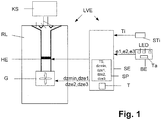
- the Fig. 1 now shows in a greatly simplified representation the backrest RL of a vehicle seat with a headrest KS arranged at the top.
- an air outflow opening LA ⁇ Integrated into the backrest as part of the air supply device LVE for the vehicle seat in the upper area of the vehicle seat is an air outflow opening LA ⁇ , via which the head, shoulder and neck area of the seat occupant can be subjected to an air flow.
- the air flow can be adjusted by means of a control unit SE by controlling or regulating a fan speed of a blower G and can be heated via a heating element HE, which can also be controlled by the control unit SE.
- the control unit SE receives at least the following signals: a switch-on signal e1, e2 or e3 for switching on the air supply device LVE and a temperature signal Ti from a temperature sensor STi, the temperature signal Ti of which informs the control unit SE about the interior temperature Ti.
- a switch-on signal e1, e2 or e3 is generated when a control element BE arranged in the vehicle is actuated, the control element having a button Ta, and when it is actuated, a desired output level is selected from a selection of 3 power levels of the air supply device by pressing the button Ta one or more times can be.
- the light-emitting diodes LED shown in the control element BE show the user which power level he has selected.
- the switch-on signal e1, e2 or e3 is sent to the control unit SE.
- control unit SE also includes a memory S in which various memory values, such as e.g. B. a temperature threshold TS or predefined target fan speeds dzmin, dze1, dze2 and dze3 are stored for the various control scenarios.
- control unit SE is designed in such a way that it switches on the heating element HE and the fan G in response to a switch-on signal e1, e2 or e3, and at least the fan G as a function of the supplied interior temperature Ti by specifying different fan speeds dzmin, dze1, dze2 and dze3 controls.
- the control unit SE also includes a so-called timer T, which can be activated when the fan is activated at a minimum speed dzmin and is used for time monitoring.
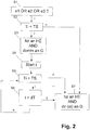
- step S1 it is checked in the control unit SE whether a switch-on signal e1, e2 or e3 for switching on the air supply device LVE is present.
- the air supply device can be operated in 3 power levels, the user being able to request that the air supply device LVE be switched on in one of the 3 power levels by pressing the Ta key accordingly.
- the switch-on signal e1, e2 or e3 is sent to the control unit SE.
- step S2 If a switch-on signal e1, e2 or e3 is present, the process goes to step S2 and there it is determined whether the temperature signal Ti indicates that the current interior temperature Ti is less than a predetermined and stored temperature threshold value TS. If this is not the case, the process goes to step S7, where the control unit SE causes the heating element HE to be switched on by sending out a heating control signal hz, the fan G to be switched on and the fan output to be controlled or regulated in such a way that the fan G also a fan speed dz (ei) dependent on the requested power level ei (where i can have the value 1, 2 or 3) is operated. This setting is retained until the user deactivates the air supply device LVE again or selects a different power level e1, e2, e3.
- step S2 If, however, it is determined in step S2 that the current interior temperature Ti is less than a predefined and stored temperature threshold value TS, the process goes to step S3.
- the control unit SE causes the heating element HE to be switched on by sending out a heating control signal hz, the fan G to be switched on and the fan output to be controlled or regulated in such a way that the fan G is operated at a predetermined and stored minimum fan speed dzmin.
- This minimum fan speed dzmin is significantly lower than the above-described fan speed dz (ei) which is dependent on the requested power level ei.
- step S4 a timer T for time measurement is started, whereby the elapsed time since the start of the fan control with the minimum fan speed can be determined.
- step S5 it is checked again whether the current interior temperature TI is still lower than the predefined and stored temperature threshold value TS. If the temperature has risen above the specified temperature threshold, the process goes to step S7 analogously to step S2, where the control unit SE switches on the heating element HE by sending out a heating control signal hz, switches on the fan G and controls or regulates the in this way Fan output causes the fan G to be operated with a fan speed dz (ei) that is dependent on the requested output level ei (where i can have the value 1, 2 or 3).
- step S5 If, however, it is determined in step S5 that the current interior temperature Ti is still lower than the predefined and stored temperature threshold value TS, a check is then made in step S6 to determine whether the time t that has elapsed since the start of the timer T is greater than a predefined time dT . If this is the case, there is also a transition from step S6 to step S7 and - as already described above - activation and Control or regulation of the heating element HE and the fan initiated. If the time t that has elapsed since the start of the timer T is not greater than a predetermined time dT, the system jumps back to step S5.
- control unit SE increases the fan output of the fan G to a fan speed dz (ei) dependent on the requested output level ei when the interior temperature Ti is greater than the specified temperature threshold value TS, but at the latest after the time t that has elapsed since the start of the timer T is greater than the specified time dT.
Landscapes
- Engineering & Computer Science (AREA)
- Aviation & Aerospace Engineering (AREA)
- Transportation (AREA)
- Mechanical Engineering (AREA)
- Air-Conditioning For Vehicles (AREA)
Claims (5)
- Siège de véhicule comprenant un dispositif d'alimentation en air, une ouverture de sortie d'air qui est prévue dans la zone supérieure du siège du véhicule et par laquelle la région couvrant la tête, les épaules et le cou de l'occupant du siège peut être soumise à un courant d'air, et le courant d'air pouvant être réglé au moyen d'une unité de commande par commande ou régulation de la vitesse de ventilateur d'une soufflante et pouvant être chauffé par un élément chauffant, et l'unité de commande recevant au moins un signal d'activation destiné à activer le dispositif d'alimentation en air et un signal de température qui informe sur la température de l'habitacle, caractérisé en ce que l'unité de commande (SE) active, en réponse au signal d'activation (e1, e2, e3), l'élément chauffant (HE) et la soufflante (G) et commande au moins la soufflante (G) en fonction de la température de l'habitacle, l'unité de commande (SE) ordonnant, en réponse au signal d'activation (e1, e2, e3), le fonctionnement de la soufflante (G) à une vitesse de rotation de ventilateur minimale spécifiée (dzmin) lorsque le signal de température (Ti) indique que la température (Ti) de l'habitacle est inférieure à une valeur de seuil de température spécifiée (TS).
- Siège de véhicule selon la revendication 1, caractérisé en ce que l'unité de commande (SE) ordonne le fonctionnement de la soufflante (G), fonctionnant à la vitesse de rotation de ventilateur minimale (dzmin), à une vitesse de rotation de ventilateur plus élevée, notamment à une vitesse de rotation de ventilateur à niveaux de puissance (dzel, dze2, dze3) dépendant d'un niveau de puissance requis du dispositif d'alimentation en air (LVE), dès que le signal de température (Ti) indique que la température (Ti) de l'habitacle n'est plus inférieure à une valeur de seuil de température spécifiée (TS).
- Siège de véhicule selon la revendication 1 ou 2, caractérisé en ce que l'unité de commande (SE) ordonne le fonctionnement de la soufflante (G) à la vitesse de rotation de ventilateur minimale (dzmin), indépendamment du signal de température (Ti), au plus tard à une vitesse de rotation de ventilateur plus élevée, notamment à une vitesse de rotation de ventilateur à niveaux de puissance (dzel, dze2, dze3) dépendant d'un niveau de puissance requis du dispositif d'alimentation en air (LVE), seulement lorsque la soufflante (G) a fonctionné à la vitesse de ventilateur minimale (dzmin) pendant plus d'un intervalle de temps (dT) .
- Siège de véhicule selon l'une des revendications précédentes, caractérisé en ce que l'unité de commande (SE) ordonne, en réponse au signal d'activation (e1, e2, e3), le fonctionnement de la soufflante (G) directement à une vitesse de rotation de ventilateur à niveaux de puissance (dzel, dze2, dze3) dépendant d'un niveau de puissance requis du dispositif d'alimentation en air (LVE), qui est supérieure à une vitesse de rotation de ventilateur minimale spécifiée (dzmin), lorsque le signal de température (Ti) indique que la température (Ti) de l'habitacle n'est pas inférieure à la valeur de seuil de température spécifiée (TS).
- Procédé de fonctionnement d'un dispositif d'alimentation en air destiné à un siège de véhicule et comprenant une ouverture de sortie d'air qui est prévue dans la zone supérieure du siège du véhicule et par laquelle la région couvrant la tête, les épaules et le cou de l'occupant du siège peut être soumise à un courant d'air, et le courant d'air pouvant être réglé au moyen d'une unité de commande par commande ou régulation de la vitesse de ventilateur d'une soufflante et pouvant être chauffé par un élément chauffant, et l'unité de commande recevant au moins un signal d'activation destiné à activer le dispositif d'alimentation en air et un signal de température qui informe sur la température de l'habitacle, caractérisé par les étapes suivantes,- (S1) vérifier la présence d'un signal d'activation (e1, e2, e3) destiné à activer le dispositif d'alimentation en air (LVE), puis si c'est le cas,- (S2) déterminer si la température (Ti) de l'habitacle dépasse une valeur de seuil de température spécifiée (TS), et si c'est le cas, activer l'élément chauffant (HE) et la soufflante (G) et commander ou réguler la puissance de la soufflante de telle manière que la soufflante (G) fonctionne à une vitesse de rotation de ventilateur à niveaux de puissance (dzel, dze2, dze3) dépendant du niveau de puissance requis du dispositif d'alimentation en air (LVE), sinon,- (S3) activer l'élément chauffant (HE) et la soufflante (G) et commander ou réguler la puissance de la soufflante de manière que la soufflante (G) fonctionne à une vitesse de rotation de ventilateur minimale spécifiée (dzmin), qui est inférieure à la vitesse de rotation de ventilateur (dzel, dze2, dze3), puis- (S4) démarrer un chronomètre (T) pour mesurer le temps, puis- (S5) vérifier si la température (Ti) de l'habitacle dépasse la valeur de seuil de température spécifiée (TS), et si c'est le cas, commander ou réguler la puissance de la soufflante de manière que la soufflante (G) fonctionne à une vitesse de rotation de ventilateur à niveaux de puissance (dzel, dze2, dze3) dépendant du niveau de puissance requis du dispositif d'alimentation en air (LVE), sinon- (S6) vérifier si la durée (t) qui s'est écoulée depuis le démarrage du chronomètre (T) est supérieure à une durée prédéterminée (dT), et si ce n'est pas le cas, retourner à (S5), sinon- (S7) commander ou réguler la puissance de la soufflante de manière que la soufflante (G) fonctionne à une vitesse de rotation de ventilateur à niveaux de puissance (dzel, dze2, dze3) dépendant du niveau de puissance requis du dispositif d'alimentation en air (LVE).
Applications Claiming Priority (2)
| Application Number | Priority Date | Filing Date | Title |
|---|---|---|---|
| DE201310221516 DE102013221516A1 (de) | 2013-10-23 | 2013-10-23 | Luftversorgungseinrichtung für einen Fahrzeugsitz und Verfahren zum Betreiben der Luftversorgungseinrichtung |
| PCT/EP2014/072438 WO2015059092A1 (fr) | 2013-10-23 | 2014-10-20 | Dispositif d'alimentation en air d'un siège de véhicule et procédé permettant de faire fonctionner ledit dispositif d'alimentation en air |
Publications (2)
| Publication Number | Publication Date |
|---|---|
| EP3060427A1 EP3060427A1 (fr) | 2016-08-31 |
| EP3060427B1 true EP3060427B1 (fr) | 2021-05-19 |
Family
ID=51743450
Family Applications (1)
| Application Number | Title | Priority Date | Filing Date |
|---|---|---|---|
| EP14786212.2A Active EP3060427B1 (fr) | 2013-10-23 | 2014-10-20 | Système d'alimentation en air pour un siège de véhicule et procédé pour fonctionnement du système d'alimentation en air |
Country Status (5)
| Country | Link |
|---|---|
| US (1) | US11052798B2 (fr) |
| EP (1) | EP3060427B1 (fr) |
| CN (1) | CN105658477B (fr) |
| DE (1) | DE102013221516A1 (fr) |
| WO (1) | WO2015059092A1 (fr) |
Families Citing this family (5)
| Publication number | Priority date | Publication date | Assignee | Title |
|---|---|---|---|---|
| DE102013221516A1 (de) * | 2013-10-23 | 2015-04-23 | Bayerische Motoren Werke Aktiengesellschaft | Luftversorgungseinrichtung für einen Fahrzeugsitz und Verfahren zum Betreiben der Luftversorgungseinrichtung |
| DE102015211858B4 (de) * | 2015-06-25 | 2025-06-12 | Bayerische Motoren Werke Aktiengesellschaft | Kraftfahrzeug |
| KR102140506B1 (ko) * | 2016-02-10 | 2020-08-04 | 젠썸 게엠베하 | 차량 시트의 사용자 경부 부위의 온도 조절 장치 |
| CN106956627A (zh) | 2017-03-20 | 2017-07-18 | 上海安闻汽车电子有限公司 | 一种汽车座椅 |
| FR3114059B1 (fr) * | 2020-09-15 | 2022-09-09 | Faurecia Sieges Dautomobile | Siège de véhicule comprenant un élément de support |
Citations (1)
| Publication number | Priority date | Publication date | Assignee | Title |
|---|---|---|---|---|
| US20030150229A1 (en) * | 2002-02-12 | 2003-08-14 | Shinji Aoki | Vehicle seat air conditioning system having electric heater and blower unit |
Family Cites Families (105)
| Publication number | Priority date | Publication date | Assignee | Title |
|---|---|---|---|---|
| JPS5948168B2 (ja) * | 1980-04-10 | 1984-11-24 | 株式会社ボッシュオートモーティブ システム | 車輛用空気調和装置の制御方法 |
| US4351425A (en) * | 1980-12-29 | 1982-09-28 | Eaton Corporation | Dual stage control for viscous fluid coupling |
| JPH01285417A (ja) * | 1988-05-10 | 1989-11-16 | Nissan Motor Co Ltd | 自動車用空調装置 |
| JP2572628B2 (ja) * | 1988-05-16 | 1997-01-16 | 株式会社ゼクセル | 車両用空調装置の風量制御装置 |
| DE3843898A1 (de) * | 1988-12-24 | 1990-06-28 | Porsche Ag | Klimatisierungssystem fuer ein fahrzeug |
| US5082173A (en) * | 1989-02-22 | 1992-01-21 | Mcmaster University | Environmental controller for a sealed structure |
| JP3028580B2 (ja) * | 1990-10-04 | 2000-04-04 | 株式会社デンソー | 車両用空調装置 |
| DE4130226C1 (fr) * | 1991-09-11 | 1993-03-11 | Webasto Ag Fahrzeugtechnik, 8035 Stockdorf, De | |
| US5524439A (en) * | 1993-11-22 | 1996-06-11 | Amerigon, Inc. | Variable temperature seat climate control system |
| US5626021A (en) * | 1993-11-22 | 1997-05-06 | Amerigon, Inc. | Variable temperature seat climate control system |
| US5873256A (en) * | 1994-07-07 | 1999-02-23 | Denniston; James G. T. | Desiccant based humidification/dehumidification system |
| US6012515A (en) * | 1996-11-27 | 2000-01-11 | Sikorsky Aircraft Corporation | System and method for automatically controlling cabin air temperature in an aircraft |
| US5974350A (en) * | 1997-06-11 | 1999-10-26 | Ford Global Technologies, Inc. | Compact fuzzy logic algorithm |
| JP3807072B2 (ja) * | 1998-02-09 | 2006-08-09 | 株式会社デンソー | 車両用空調装置 |
| JP2000142080A (ja) * | 1998-11-05 | 2000-05-23 | Sanden Corp | 建設車両用空調装置 |
| US6237675B1 (en) * | 1999-06-14 | 2001-05-29 | Ford Global Technolgies, Inc. | Automatic temperature controlled seats |
| US6793016B2 (en) * | 2000-01-28 | 2004-09-21 | Denso Corporation | Vehicle air conditioning system with seat air conditioning unit |
| JP2001213243A (ja) * | 2000-01-31 | 2001-08-07 | Pioneer Electronic Corp | 車載用情報処理装置 |
| JP4317902B2 (ja) * | 2000-05-19 | 2009-08-19 | 株式会社デンソー | 車両用空調装置 |
| DE10060610B4 (de) * | 2000-12-05 | 2005-09-22 | Webasto Ag | Fahrzeugdach mit integriertem Lüfter |
| DE10105094B4 (de) * | 2001-02-05 | 2004-07-08 | W.E.T. Automotive Systems Ag | Fahrzeugsitz |
| US6439468B1 (en) * | 2001-04-09 | 2002-08-27 | Delphi Technologies, Inc. | Acoustic HVAC control system |
| DE10226008B4 (de) * | 2002-06-12 | 2006-02-02 | Daimlerchrysler Ag | Luftversorgungseinrichtung für einen Fahrzeugsitz |
| DE10257587B3 (de) * | 2002-12-09 | 2004-04-15 | Daimlerchrysler Ag | Verfahren zur Regelung einer Klimaanlage für ein Fahrzeug mit verschließbaren Karosserieöffnungen |
| JP2004255921A (ja) * | 2003-02-24 | 2004-09-16 | Denso Corp | 車両用換気装置および車両用空調装置 |
| DE10316275B4 (de) * | 2003-04-08 | 2009-06-18 | Johnson Controls Gmbh | Fahrzeugsitz |
| US7084774B2 (en) * | 2003-11-13 | 2006-08-01 | International Business Machines Corporation | Temperature control system |
| US7204429B2 (en) * | 2004-04-28 | 2007-04-17 | Intelligent Power Management, Inc | Controller for forced-air HVAC system |
| DE102004030707B4 (de) * | 2004-06-25 | 2007-02-15 | Daimlerchrysler Ag | Verfahren zum Betreiben einer Luftversorgungseinrichtung für einen Fahrzeugsitz |
| DE102004030705B3 (de) | 2004-06-25 | 2005-12-01 | Daimlerchrysler Ag | Luftversorgungseinrichtung für einen Fahrzeugsitz sowie Verfahren zum Betreiben derselben |
| DE102004030706B3 (de) * | 2004-06-25 | 2005-09-08 | Daimlerchrysler Ag | Luftversorgungseinrichtung für einen Fahrzeugsitz sowie Verfahren zum Betreiben derselben |
| US20060037565A1 (en) * | 2004-08-18 | 2006-02-23 | Coates George J | Vehicle mounted filter assembly for entrapment of ambient air pollutants |
| DE102005003086B4 (de) * | 2005-01-22 | 2012-06-06 | Bayerische Motoren Werke Aktiengesellschaft | Verfahren zum Ermitteln der Soll-Ausblastemperatur einer automatischen Klimaanlage in einem Cabrio |
| US20070000659A1 (en) * | 2005-06-29 | 2007-01-04 | Schlanger Steven E | Vehicle environmental control system and related method |
| US7513439B2 (en) * | 2005-09-15 | 2009-04-07 | Nissan Technical Center North America, Inc. | Automatic climate control system for vehicle |
| US8565969B2 (en) * | 2007-04-03 | 2013-10-22 | Clean Emissions Technologies, Inc. | Over the road/traction/cabin comfort retrofit |
| DE102006015667B4 (de) * | 2006-04-04 | 2009-11-12 | Daimler Ag | Rückenlehne für einen Kraftfahrzeugsitz |
| US20080014852A1 (en) * | 2006-07-11 | 2008-01-17 | Mielke Richard A | Air conditioner control for vehicular no-idle system using batteries |
| US7962441B2 (en) * | 2006-09-22 | 2011-06-14 | Denso Corporation | Air conditioner for vehicle and controlling method thereof |
| US7797958B2 (en) * | 2006-11-15 | 2010-09-21 | Glacier Bay, Inc. | HVAC system controlled by a battery management system |
| JP4325669B2 (ja) * | 2006-12-26 | 2009-09-02 | トヨタ自動車株式会社 | 車両用空調装置 |
| JP4697136B2 (ja) * | 2006-12-28 | 2011-06-08 | 株式会社デンソー | データ記録装置の放熱制御装置 |
| JP4321594B2 (ja) * | 2007-01-17 | 2009-08-26 | 株式会社デンソー | 車両用空調装置 |
| US20090130966A1 (en) * | 2007-11-16 | 2009-05-21 | David Wayne Tucker | Vehicle cabin venting arrangement |
| JP4990115B2 (ja) * | 2007-12-06 | 2012-08-01 | 株式会社デンソー | 位置範囲設定装置、移動物体搭載装置の制御方法および制御装置、ならびに車両用空調装置の制御方法および制御装置 |
| EP2402209B1 (fr) * | 2008-01-24 | 2013-06-05 | Eberspächer catem GmbH & Co. KG | Chauffage électrique additionel pour vehicules |
| US20100080399A1 (en) * | 2008-09-30 | 2010-04-01 | Visteon Global Technologies, Inc. | Method For Reducing Vehicle Noise |
| US20100089563A1 (en) * | 2008-10-15 | 2010-04-15 | Sundhar Shaam P | Vehicle air conditioning improvement |
| CN101737910A (zh) * | 2008-11-07 | 2010-06-16 | 塞莫金公司 | 新鲜空气箱 |
| CA2691245C (fr) * | 2009-01-28 | 2018-09-25 | Bryn Gough Magee | Entree amelioree |
| US8209073B2 (en) * | 2009-05-06 | 2012-06-26 | Ford Global Technologies, Llc | Climate control system and method for optimizing energy consumption of a vehicle |
| JP2011020478A (ja) * | 2009-07-13 | 2011-02-03 | Denso Corp | 車両用空調装置 |
| JP5508625B2 (ja) * | 2009-12-14 | 2014-06-04 | トヨタ自動車株式会社 | 車両の制御装置及び車両の制御方法 |
| JP5475501B2 (ja) * | 2010-02-24 | 2014-04-16 | サンデン株式会社 | 車両用空調装置 |
| JP4952822B2 (ja) * | 2010-05-24 | 2012-06-13 | ダイキン工業株式会社 | 熱源側熱交換器用ファンの制御方法および空気調和装置 |
| US20120097465A1 (en) * | 2010-10-22 | 2012-04-26 | Gm Global Technology Operations, Inc. | System and method for controlling a shutter in a vehicle via a cooling fan duty-cycle |
| US8589024B2 (en) * | 2010-11-29 | 2013-11-19 | GM Global Technology Operations LLC | Thermal conditioning of rechargeable energy storage systems of vehicles |
| CA2826476C (fr) * | 2011-02-04 | 2015-06-23 | Bombardier Transportation Gmbh | Systeme de ventilation pour un vehicule de transport de passagers |
| JP5673221B2 (ja) * | 2011-03-03 | 2015-02-18 | 富士通株式会社 | 風量制御装置、風量制御方法及び風量制御プログラム |
| US20120234815A1 (en) * | 2011-03-18 | 2012-09-20 | GM Global Technology Operations LLC | Time sensitive heated seat control |
| US9150132B2 (en) * | 2011-06-13 | 2015-10-06 | Ford Global Technologies, Llc | Vehicle comfort system with efficient coordination of complementary thermal units |
| JP5246374B1 (ja) * | 2011-06-15 | 2013-07-24 | トヨタ自動車株式会社 | 車両用暖房制御装置、方法及びプログラム |
| DE102012014678A1 (de) * | 2011-08-19 | 2013-02-21 | W.E.T. Automotive Systems Ag | Heizeinrichtung |
| JP5742607B2 (ja) * | 2011-09-08 | 2015-07-01 | 三菱自動車工業株式会社 | ハイブリッド電気自動車の制御装置 |
| KR101305830B1 (ko) * | 2011-11-16 | 2013-09-06 | 현대자동차주식회사 | 차량의 실내 환기방법 |
| KR101345849B1 (ko) * | 2011-11-22 | 2013-12-30 | 갑을오토텍(주) | 시트용 통풍장치 |
| KR101345872B1 (ko) * | 2012-01-04 | 2013-12-30 | 갑을오토텍(주) | 차량용 시트 냉난방장치 및 그 냉난방방법 |
| US9371024B2 (en) * | 2012-02-13 | 2016-06-21 | Denso Corporation | Air-conditioner for vehicle |
| EP2634021B1 (fr) * | 2012-03-02 | 2015-04-08 | Halla Visteon Climate Control Corp. | Système de pompe à chaleur pour véhicule et procédé de commande de celui-ci |
| US8839632B2 (en) * | 2012-03-09 | 2014-09-23 | Visteon Global Technologies, Inc. | Control strategy for a zonal heating, ventilating, and air conditioning system of a vehicle |
| US8849487B2 (en) * | 2012-06-07 | 2014-09-30 | Ford Global Technologies, Llc | Utilization of vehicle portal states to assess interior comfort and adjust vehicle operation to provide additional fuel economy |
| US9494954B2 (en) * | 2012-07-26 | 2016-11-15 | Dell Products Lp | Thermal control systems and methods for information handling systems |
| US11079126B2 (en) * | 2012-09-11 | 2021-08-03 | Ventamatic, Ltd. | Climate smart fan ventilation |
| US9092030B2 (en) * | 2013-03-14 | 2015-07-28 | Rockwell Automation Technologies, Inc. | Method to implement drive diagnostics and prognostics automatically |
| CN105324272B (zh) * | 2013-07-02 | 2017-07-21 | 松下知识产权经营株式会社 | 交通工具用制热系统 |
| DE102013214554A1 (de) * | 2013-07-25 | 2015-01-29 | Bayerische Motoren Werke Aktiengesellschaft | Verfahren zum Heizen des Innenraums eines Fahrzeugs |
| DE102013214555A1 (de) * | 2013-07-25 | 2015-01-29 | Bayerische Motoren Werke Aktiengesellschaft | Verfahren zum Heizen des Innenraums eines Fahrzeugs |
| EP2832918B1 (fr) * | 2013-08-01 | 2018-01-31 | Electrolux Appliances Aktiebolag | Appareil de traitement du linge et procédé pour faire fonctionner un tel appareil |
| DE102013221516A1 (de) * | 2013-10-23 | 2015-04-23 | Bayerische Motoren Werke Aktiengesellschaft | Luftversorgungseinrichtung für einen Fahrzeugsitz und Verfahren zum Betreiben der Luftversorgungseinrichtung |
| KR101566735B1 (ko) * | 2013-12-05 | 2015-11-06 | 현대자동차 주식회사 | 하이브리드 차량의 실내 난방 방법 및 장치 |
| US20150231947A1 (en) * | 2014-02-17 | 2015-08-20 | GM Global Technology Operations LLC | Systems and methods for ventilation |
| US10414245B2 (en) * | 2014-08-12 | 2019-09-17 | David Horn | Vehicle ventilation system |
| JP6422295B2 (ja) * | 2014-10-08 | 2018-11-14 | キヤノン株式会社 | 画像形成装置 |
| US9822696B2 (en) * | 2015-02-13 | 2017-11-21 | Ford Global Technologies, Llc | Turbocharger system having an air-cooled wastegate actuator |
| CN105987550B (zh) * | 2015-02-27 | 2021-04-09 | 开利公司 | 制冷系统冷凝器风扇控制 |
| JP6222159B2 (ja) * | 2015-04-10 | 2017-11-01 | トヨタ自動車株式会社 | 車載二次電池の冷却システム |
| DE102015218825B4 (de) * | 2015-09-30 | 2026-03-12 | Bayerische Motoren Werke Aktiengesellschaft | Verfahren und Steuerungssystem zur Klimatisierung eines Fahrzeugs |
| US10823185B2 (en) * | 2015-12-18 | 2020-11-03 | Carrier Corporation | Motor interface assembly and a method of using the same |
| AU2017101887A4 (en) * | 2016-01-16 | 2020-10-08 | Dometic Sweden Ab | Parking cooler |
| KR102140506B1 (ko) * | 2016-02-10 | 2020-08-04 | 젠썸 게엠베하 | 차량 시트의 사용자 경부 부위의 온도 조절 장치 |
| JP6904333B2 (ja) * | 2016-03-24 | 2021-07-14 | 日本電気株式会社 | 冷却装置、制御方法および記憶媒体 |
| US20170297412A1 (en) * | 2016-04-13 | 2017-10-19 | GM Global Technology Operations LLC | Method of controlling a hvac system of a vehicle |
| US10209750B2 (en) * | 2016-05-02 | 2019-02-19 | Samsung Electronics Co., Ltd. | SSD driven system level thermal management |
| KR101836664B1 (ko) * | 2016-07-08 | 2018-04-20 | 현대자동차주식회사 | 차량용 냉온 헤드레스트의 작동 제어방법 |
| US10571979B2 (en) * | 2017-03-16 | 2020-02-25 | Dell Products L.P. | Cooling fan speed control profile |
| JP6496790B2 (ja) * | 2017-09-08 | 2019-04-03 | 株式会社Subaru | 車載機器冷却装置 |
| EP3653946B1 (fr) * | 2017-10-19 | 2023-07-05 | GD Midea Air-Conditioning Equipment Co., Ltd. | Climatiseur, procédé et dispositif de commande associé, et support de stockage lisible par ordinateur |
| US9994100B1 (en) * | 2017-10-27 | 2018-06-12 | GM Global Technology Operations LLC | Shutter control arrangement for a vehicle |
| US10479163B2 (en) * | 2017-11-14 | 2019-11-19 | GM Global Technology Operations LLC | Method for controlling a thermal comfort control system for ride share vehicles |
| US10836236B2 (en) * | 2017-12-01 | 2020-11-17 | International Truck Intellectual Property Company Llc | Vehicle engine-off heating and cooling climate control using super-heated fluid for heating |
| US10518602B2 (en) * | 2017-12-08 | 2019-12-31 | Ford Global Technologies, Llc | Automatic control of heating and cooling of a vehicle seating assembly pursuant to predictive modeling that recalibrates based on occupant manual control |
| WO2019119761A1 (fr) * | 2017-12-18 | 2019-06-27 | 青岛海信激光显示股份有限公司 | Procédé permettant d'activer un ventilateur de dissipation de chaleur |
| US20190191812A1 (en) * | 2017-12-22 | 2019-06-27 | Mohamed Salem | Hat with forced air cooling |
| US10801392B2 (en) * | 2018-05-25 | 2020-10-13 | Ford Global Technologies, Llc | Systems and methods for expedited vehicle soak |
| TWI705188B (zh) * | 2018-08-01 | 2020-09-21 | 緯創資通股份有限公司 | 風扇系統與風扇系統的抑音方法 |
-
2013
- 2013-10-23 DE DE201310221516 patent/DE102013221516A1/de not_active Withdrawn
-
2014
- 2014-10-20 CN CN201480058067.9A patent/CN105658477B/zh active Active
- 2014-10-20 WO PCT/EP2014/072438 patent/WO2015059092A1/fr not_active Ceased
- 2014-10-20 EP EP14786212.2A patent/EP3060427B1/fr active Active
-
2016
- 2016-04-22 US US15/136,073 patent/US11052798B2/en active Active
Patent Citations (1)
| Publication number | Priority date | Publication date | Assignee | Title |
|---|---|---|---|---|
| US20030150229A1 (en) * | 2002-02-12 | 2003-08-14 | Shinji Aoki | Vehicle seat air conditioning system having electric heater and blower unit |
Also Published As
| Publication number | Publication date |
|---|---|
| DE102013221516A1 (de) | 2015-04-23 |
| CN105658477A (zh) | 2016-06-08 |
| WO2015059092A1 (fr) | 2015-04-30 |
| EP3060427A1 (fr) | 2016-08-31 |
| US20160236599A1 (en) | 2016-08-18 |
| US11052798B2 (en) | 2021-07-06 |
| CN105658477B (zh) | 2018-07-17 |
Similar Documents
| Publication | Publication Date | Title |
|---|---|---|
| EP3060427B1 (fr) | Système d'alimentation en air pour un siège de véhicule et procédé pour fonctionnement du système d'alimentation en air | |
| EP2082919B1 (fr) | Chauffage électrique d'appoint pour un véhicule automobile | |
| EP2082920B1 (fr) | Chauffage électrique d'appoint pour véhicule automobile | |
| DE102012221723B4 (de) | Heizungssteuereinheit und heizungssteuerverfahren für eine elektrische fahrzeugsitzheizung | |
| DE102004030707B4 (de) | Verfahren zum Betreiben einer Luftversorgungseinrichtung für einen Fahrzeugsitz | |
| EP1778521A2 (fr) | Système d'alimentation en air pour un siège de véhicule et procédé pour son fonctionnement | |
| DE112021003577T5 (de) | Steuerung von Funktionen eines Fahrzeuglenkrads | |
| DE102020007458A1 (de) | Verfahren zur automatischen Steuerung einer Sitzklimatisierung in einem Fahrzeug | |
| DE102012023366A1 (de) | Verfahren für den Betrieb einer in einem Kraftfahrzeug einsetzbaren Heizung, Heizung für ein Bauteil eines Kraftfahrzeugs und Kraftfahrzeug | |
| DE10337771B4 (de) | Steuerungsvorrichtung für eine Heizeinrichtung und Verfahren zur Steuerung einer Heizeinrichtung | |
| DE102016009831A1 (de) | Verfahren zum Beheizen von Flächen im Innenraum eines Fahrzeugs | |
| DE10002286B4 (de) | Vorrichtung zur Steuerung einer Einrichtung zur Klimatisierung eines Fahrzeugsitzes | |
| DE10007195A1 (de) | Verfahren zum Betreiben eines Heizgeräts, insbesondere Fahrzeug-Heizgerät | |
| DE102006034466B4 (de) | Kraftfahrzeug | |
| DE19830274A1 (de) | Heizungsanlage für Kraftfahrzeuge | |
| WO2004106094A1 (fr) | Installation de chauffage et/ou de climatisation de vehicule et procede pour la regulation du chauffage et/ou de la climatisation dans des vehicules | |
| EP1524139B1 (fr) | Chauffage supplémentaire à élément PTC pour véhicules | |
| DE102005054618B4 (de) | Verfahren zum Beheizen eines Fahrgastraums eines Fahrzeugs | |
| DE102023202723A1 (de) | Steuerung und Verfahren für eine Sitzheizung eines Kraftfahrzeugs | |
| DE102006011522A1 (de) | Heizvorrichtung mit einer Niedertemperaturheizung | |
| EP2339893B1 (fr) | Dispositif d'appareil de cuisson | |
| DE102011110134A1 (de) | Sollwertverschiebung einer KFZ-Klimaanlage | |
| DE102014220556A1 (de) | Verfahren zum Betreiben eines Fahrzeugsitzes, Fahrzeugsitz und Fahrzeug | |
| WO2010066650A2 (fr) | Procédé de réglage et de commande d'un mécanisme de positionnement pour un brûleur | |
| DE102017001169A1 (de) | Heizgerät zur Wassererwärmung und Betriebsverfahren |
Legal Events
| Date | Code | Title | Description |
|---|---|---|---|
| PUAI | Public reference made under article 153(3) epc to a published international application that has entered the european phase |
Free format text: ORIGINAL CODE: 0009012 |
|
| 17P | Request for examination filed |
Effective date: 20160511 |
|
| AK | Designated contracting states |
Kind code of ref document: A1 Designated state(s): AL AT BE BG CH CY CZ DE DK EE ES FI FR GB GR HR HU IE IS IT LI LT LU LV MC MK MT NL NO PL PT RO RS SE SI SK SM TR |
|
| AX | Request for extension of the european patent |
Extension state: BA ME |
|
| DAX | Request for extension of the european patent (deleted) | ||
| STAA | Information on the status of an ep patent application or granted ep patent |
Free format text: STATUS: EXAMINATION IS IN PROGRESS |
|
| 17Q | First examination report despatched |
Effective date: 20190424 |
|
| GRAP | Despatch of communication of intention to grant a patent |
Free format text: ORIGINAL CODE: EPIDOSNIGR1 |
|
| STAA | Information on the status of an ep patent application or granted ep patent |
Free format text: STATUS: GRANT OF PATENT IS INTENDED |
|
| INTG | Intention to grant announced |
Effective date: 20210125 |
|
| GRAS | Grant fee paid |
Free format text: ORIGINAL CODE: EPIDOSNIGR3 |
|
| GRAA | (expected) grant |
Free format text: ORIGINAL CODE: 0009210 |
|
| STAA | Information on the status of an ep patent application or granted ep patent |
Free format text: STATUS: THE PATENT HAS BEEN GRANTED |
|
| AK | Designated contracting states |
Kind code of ref document: B1 Designated state(s): AL AT BE BG CH CY CZ DE DK EE ES FI FR GB GR HR HU IE IS IT LI LT LU LV MC MK MT NL NO PL PT RO RS SE SI SK SM TR |
|
| REG | Reference to a national code |
Ref country code: GB Ref legal event code: FG4D Free format text: NOT ENGLISH |
|
| REG | Reference to a national code |
Ref country code: CH Ref legal event code: EP |
|
| REG | Reference to a national code |
Ref country code: DE Ref legal event code: R096 Ref document number: 502014015601 Country of ref document: DE |
|
| REG | Reference to a national code |
Ref country code: AT Ref legal event code: REF Ref document number: 1393666 Country of ref document: AT Kind code of ref document: T Effective date: 20210615 |
|
| REG | Reference to a national code |
Ref country code: IE Ref legal event code: FG4D Free format text: LANGUAGE OF EP DOCUMENT: GERMAN |
|
| REG | Reference to a national code |
Ref country code: LT Ref legal event code: MG9D |
|
| REG | Reference to a national code |
Ref country code: NL Ref legal event code: MP Effective date: 20210519 |
|
| PG25 | Lapsed in a contracting state [announced via postgrant information from national office to epo] |
Ref country code: HR Free format text: LAPSE BECAUSE OF FAILURE TO SUBMIT A TRANSLATION OF THE DESCRIPTION OR TO PAY THE FEE WITHIN THE PRESCRIBED TIME-LIMIT Effective date: 20210519 Ref country code: FI Free format text: LAPSE BECAUSE OF FAILURE TO SUBMIT A TRANSLATION OF THE DESCRIPTION OR TO PAY THE FEE WITHIN THE PRESCRIBED TIME-LIMIT Effective date: 20210519 Ref country code: LT Free format text: LAPSE BECAUSE OF FAILURE TO SUBMIT A TRANSLATION OF THE DESCRIPTION OR TO PAY THE FEE WITHIN THE PRESCRIBED TIME-LIMIT Effective date: 20210519 Ref country code: BG Free format text: LAPSE BECAUSE OF FAILURE TO SUBMIT A TRANSLATION OF THE DESCRIPTION OR TO PAY THE FEE WITHIN THE PRESCRIBED TIME-LIMIT Effective date: 20210819 |
|
| PG25 | Lapsed in a contracting state [announced via postgrant information from national office to epo] |
Ref country code: ES Free format text: LAPSE BECAUSE OF FAILURE TO SUBMIT A TRANSLATION OF THE DESCRIPTION OR TO PAY THE FEE WITHIN THE PRESCRIBED TIME-LIMIT Effective date: 20210519 Ref country code: NO Free format text: LAPSE BECAUSE OF FAILURE TO SUBMIT A TRANSLATION OF THE DESCRIPTION OR TO PAY THE FEE WITHIN THE PRESCRIBED TIME-LIMIT Effective date: 20210819 Ref country code: PL Free format text: LAPSE BECAUSE OF FAILURE TO SUBMIT A TRANSLATION OF THE DESCRIPTION OR TO PAY THE FEE WITHIN THE PRESCRIBED TIME-LIMIT Effective date: 20210519 Ref country code: PT Free format text: LAPSE BECAUSE OF FAILURE TO SUBMIT A TRANSLATION OF THE DESCRIPTION OR TO PAY THE FEE WITHIN THE PRESCRIBED TIME-LIMIT Effective date: 20210920 Ref country code: RS Free format text: LAPSE BECAUSE OF FAILURE TO SUBMIT A TRANSLATION OF THE DESCRIPTION OR TO PAY THE FEE WITHIN THE PRESCRIBED TIME-LIMIT Effective date: 20210519 Ref country code: SE Free format text: LAPSE BECAUSE OF FAILURE TO SUBMIT A TRANSLATION OF THE DESCRIPTION OR TO PAY THE FEE WITHIN THE PRESCRIBED TIME-LIMIT Effective date: 20210519 Ref country code: LV Free format text: LAPSE BECAUSE OF FAILURE TO SUBMIT A TRANSLATION OF THE DESCRIPTION OR TO PAY THE FEE WITHIN THE PRESCRIBED TIME-LIMIT Effective date: 20210519 Ref country code: GR Free format text: LAPSE BECAUSE OF FAILURE TO SUBMIT A TRANSLATION OF THE DESCRIPTION OR TO PAY THE FEE WITHIN THE PRESCRIBED TIME-LIMIT Effective date: 20210820 Ref country code: IS Free format text: LAPSE BECAUSE OF FAILURE TO SUBMIT A TRANSLATION OF THE DESCRIPTION OR TO PAY THE FEE WITHIN THE PRESCRIBED TIME-LIMIT Effective date: 20210919 |
|
| PG25 | Lapsed in a contracting state [announced via postgrant information from national office to epo] |
Ref country code: NL Free format text: LAPSE BECAUSE OF FAILURE TO SUBMIT A TRANSLATION OF THE DESCRIPTION OR TO PAY THE FEE WITHIN THE PRESCRIBED TIME-LIMIT Effective date: 20210519 |
|
| PG25 | Lapsed in a contracting state [announced via postgrant information from national office to epo] |
Ref country code: SM Free format text: LAPSE BECAUSE OF FAILURE TO SUBMIT A TRANSLATION OF THE DESCRIPTION OR TO PAY THE FEE WITHIN THE PRESCRIBED TIME-LIMIT Effective date: 20210519 Ref country code: SK Free format text: LAPSE BECAUSE OF FAILURE TO SUBMIT A TRANSLATION OF THE DESCRIPTION OR TO PAY THE FEE WITHIN THE PRESCRIBED TIME-LIMIT Effective date: 20210519 Ref country code: DK Free format text: LAPSE BECAUSE OF FAILURE TO SUBMIT A TRANSLATION OF THE DESCRIPTION OR TO PAY THE FEE WITHIN THE PRESCRIBED TIME-LIMIT Effective date: 20210519 Ref country code: CZ Free format text: LAPSE BECAUSE OF FAILURE TO SUBMIT A TRANSLATION OF THE DESCRIPTION OR TO PAY THE FEE WITHIN THE PRESCRIBED TIME-LIMIT Effective date: 20210519 Ref country code: EE Free format text: LAPSE BECAUSE OF FAILURE TO SUBMIT A TRANSLATION OF THE DESCRIPTION OR TO PAY THE FEE WITHIN THE PRESCRIBED TIME-LIMIT Effective date: 20210519 Ref country code: RO Free format text: LAPSE BECAUSE OF FAILURE TO SUBMIT A TRANSLATION OF THE DESCRIPTION OR TO PAY THE FEE WITHIN THE PRESCRIBED TIME-LIMIT Effective date: 20210519 |
|
| REG | Reference to a national code |
Ref country code: DE Ref legal event code: R097 Ref document number: 502014015601 Country of ref document: DE |
|
| PLBE | No opposition filed within time limit |
Free format text: ORIGINAL CODE: 0009261 |
|
| STAA | Information on the status of an ep patent application or granted ep patent |
Free format text: STATUS: NO OPPOSITION FILED WITHIN TIME LIMIT |
|
| 26N | No opposition filed |
Effective date: 20220222 |
|
| REG | Reference to a national code |
Ref country code: CH Ref legal event code: PL |
|
| PG25 | Lapsed in a contracting state [announced via postgrant information from national office to epo] |
Ref country code: IS Free format text: LAPSE BECAUSE OF FAILURE TO SUBMIT A TRANSLATION OF THE DESCRIPTION OR TO PAY THE FEE WITHIN THE PRESCRIBED TIME-LIMIT Effective date: 20210919 Ref country code: AL Free format text: LAPSE BECAUSE OF FAILURE TO SUBMIT A TRANSLATION OF THE DESCRIPTION OR TO PAY THE FEE WITHIN THE PRESCRIBED TIME-LIMIT Effective date: 20210519 |
|
| REG | Reference to a national code |
Ref country code: BE Ref legal event code: MM Effective date: 20211031 |
|
| PG25 | Lapsed in a contracting state [announced via postgrant information from national office to epo] |
Ref country code: MC Free format text: LAPSE BECAUSE OF FAILURE TO SUBMIT A TRANSLATION OF THE DESCRIPTION OR TO PAY THE FEE WITHIN THE PRESCRIBED TIME-LIMIT Effective date: 20210519 |
|
| PG25 | Lapsed in a contracting state [announced via postgrant information from national office to epo] |
Ref country code: LU Free format text: LAPSE BECAUSE OF NON-PAYMENT OF DUE FEES Effective date: 20211020 Ref country code: BE Free format text: LAPSE BECAUSE OF NON-PAYMENT OF DUE FEES Effective date: 20211031 |
|
| PG25 | Lapsed in a contracting state [announced via postgrant information from national office to epo] |
Ref country code: LI Free format text: LAPSE BECAUSE OF NON-PAYMENT OF DUE FEES Effective date: 20211031 Ref country code: CH Free format text: LAPSE BECAUSE OF NON-PAYMENT OF DUE FEES Effective date: 20211031 |
|
| PG25 | Lapsed in a contracting state [announced via postgrant information from national office to epo] |
Ref country code: IE Free format text: LAPSE BECAUSE OF NON-PAYMENT OF DUE FEES Effective date: 20211020 |
|
| REG | Reference to a national code |
Ref country code: AT Ref legal event code: MM01 Ref document number: 1393666 Country of ref document: AT Kind code of ref document: T Effective date: 20211020 |
|
| PG25 | Lapsed in a contracting state [announced via postgrant information from national office to epo] |
Ref country code: AT Free format text: LAPSE BECAUSE OF NON-PAYMENT OF DUE FEES Effective date: 20211020 |
|
| PG25 | Lapsed in a contracting state [announced via postgrant information from national office to epo] |
Ref country code: HU Free format text: LAPSE BECAUSE OF FAILURE TO SUBMIT A TRANSLATION OF THE DESCRIPTION OR TO PAY THE FEE WITHIN THE PRESCRIBED TIME-LIMIT; INVALID AB INITIO Effective date: 20141020 |
|
| P01 | Opt-out of the competence of the unified patent court (upc) registered |
Effective date: 20230502 |
|
| PG25 | Lapsed in a contracting state [announced via postgrant information from national office to epo] |
Ref country code: CY Free format text: LAPSE BECAUSE OF FAILURE TO SUBMIT A TRANSLATION OF THE DESCRIPTION OR TO PAY THE FEE WITHIN THE PRESCRIBED TIME-LIMIT Effective date: 20210519 |
|
| PG25 | Lapsed in a contracting state [announced via postgrant information from national office to epo] |
Ref country code: MK Free format text: LAPSE BECAUSE OF FAILURE TO SUBMIT A TRANSLATION OF THE DESCRIPTION OR TO PAY THE FEE WITHIN THE PRESCRIBED TIME-LIMIT Effective date: 20210519 |
|
| PG25 | Lapsed in a contracting state [announced via postgrant information from national office to epo] |
Ref country code: TR Free format text: LAPSE BECAUSE OF FAILURE TO SUBMIT A TRANSLATION OF THE DESCRIPTION OR TO PAY THE FEE WITHIN THE PRESCRIBED TIME-LIMIT Effective date: 20210519 |
|
| PG25 | Lapsed in a contracting state [announced via postgrant information from national office to epo] |
Ref country code: MT Free format text: LAPSE BECAUSE OF FAILURE TO SUBMIT A TRANSLATION OF THE DESCRIPTION OR TO PAY THE FEE WITHIN THE PRESCRIBED TIME-LIMIT Effective date: 20210519 |
|
| PGFP | Annual fee paid to national office [announced via postgrant information from national office to epo] |
Ref country code: DE Payment date: 20251021 Year of fee payment: 12 |
|
| PGFP | Annual fee paid to national office [announced via postgrant information from national office to epo] |
Ref country code: GB Payment date: 20251024 Year of fee payment: 12 |
|
| PGFP | Annual fee paid to national office [announced via postgrant information from national office to epo] |
Ref country code: IT Payment date: 20251031 Year of fee payment: 12 |
|
| PGFP | Annual fee paid to national office [announced via postgrant information from national office to epo] |
Ref country code: FR Payment date: 20251024 Year of fee payment: 12 |