EP3060433B1 - Système de siège - Google Patents
Système de siège Download PDFInfo
- Publication number
- EP3060433B1 EP3060433B1 EP14786689.1A EP14786689A EP3060433B1 EP 3060433 B1 EP3060433 B1 EP 3060433B1 EP 14786689 A EP14786689 A EP 14786689A EP 3060433 B1 EP3060433 B1 EP 3060433B1
- Authority
- EP
- European Patent Office
- Prior art keywords
- seat
- backrest
- bead
- seat arrangement
- pressure load
- Prior art date
- Legal status (The legal status is an assumption and is not a legal conclusion. Google has not performed a legal analysis and makes no representation as to the accuracy of the status listed.)
- Active
Links
Images


Classifications
-
- B—PERFORMING OPERATIONS; TRANSPORTING
- B60—VEHICLES IN GENERAL
- B60R—VEHICLES, VEHICLE FITTINGS, OR VEHICLE PARTS, NOT OTHERWISE PROVIDED FOR
- B60R21/00—Arrangements or fittings on vehicles for protecting or preventing injuries to occupants or pedestrians in case of accidents or other traffic risks
- B60R21/02—Occupant safety arrangements or fittings, e.g. crash pads
- B60R21/16—Inflatable occupant restraints or confinements designed to inflate upon impact or impending impact, e.g. air bags
- B60R21/20—Arrangements for storing inflatable members in their non-use or deflated condition; Arrangement or mounting of air bag modules or components
- B60R21/207—Arrangements for storing inflatable members in their non-use or deflated condition; Arrangement or mounting of air bag modules or components in vehicle seats
-
- B—PERFORMING OPERATIONS; TRANSPORTING
- B60—VEHICLES IN GENERAL
- B60N—SEATS SPECIALLY ADAPTED FOR VEHICLES; VEHICLE PASSENGER ACCOMMODATION NOT OTHERWISE PROVIDED FOR
- B60N2/00—Seats specially adapted for vehicles; Arrangement or mounting of seats in vehicles
- B60N2/90—Details or parts not otherwise provided for
- B60N2/986—Side-rests
-
- B—PERFORMING OPERATIONS; TRANSPORTING
- B60—VEHICLES IN GENERAL
- B60N—SEATS SPECIALLY ADAPTED FOR VEHICLES; VEHICLE PASSENGER ACCOMMODATION NOT OTHERWISE PROVIDED FOR
- B60N2/00—Seats specially adapted for vehicles; Arrangement or mounting of seats in vehicles
- B60N2/002—Seats provided with an occupancy detection means mounted therein or thereon
- B60N2/0021—Seats provided with an occupancy detection means mounted therein or thereon characterised by the type of sensor or measurement
- B60N2/003—Seats provided with an occupancy detection means mounted therein or thereon characterised by the type of sensor or measurement characterised by the sensor mounting location in or on the seat
-
- B—PERFORMING OPERATIONS; TRANSPORTING
- B60—VEHICLES IN GENERAL
- B60N—SEATS SPECIALLY ADAPTED FOR VEHICLES; VEHICLE PASSENGER ACCOMMODATION NOT OTHERWISE PROVIDED FOR
- B60N2/00—Seats specially adapted for vehicles; Arrangement or mounting of seats in vehicles
- B60N2/002—Seats provided with an occupancy detection means mounted therein or thereon
- B60N2/0021—Seats provided with an occupancy detection means mounted therein or thereon characterised by the type of sensor or measurement
- B60N2/0035—Seats provided with an occupancy detection means mounted therein or thereon characterised by the type of sensor or measurement characterised by the sensor data transmission, e.g. wired connections or wireless transmitters therefor; characterised by the sensor data processing, e.g. seat sensor signal amplification or electric circuits for providing seat sensor information
-
- B—PERFORMING OPERATIONS; TRANSPORTING
- B60—VEHICLES IN GENERAL
- B60N—SEATS SPECIALLY ADAPTED FOR VEHICLES; VEHICLE PASSENGER ACCOMMODATION NOT OTHERWISE PROVIDED FOR
- B60N2210/00—Sensor types, e.g. for passenger detection systems or for controlling seats
- B60N2210/40—Force or pressure sensors
-
- B—PERFORMING OPERATIONS; TRANSPORTING
- B60—VEHICLES IN GENERAL
- B60N—SEATS SPECIALLY ADAPTED FOR VEHICLES; VEHICLE PASSENGER ACCOMMODATION NOT OTHERWISE PROVIDED FOR
- B60N2230/00—Communication or electronic aspects
- B60N2230/20—Wireless data transmission
Definitions
- the invention relates to a trained according to the preamble of claim 1 seat assembly for a motor vehicle.
- a seat assembly of the type mentioned is, for example DE 100 18 170 A1 known.
- a side airbag device adjacent to a side boundary of a seatback's seat assembly is integrated with the seatback to provide a shock load on an exterior side structure of a vehicle body, such as a side impact of another vehicle, one in a passenger compartment of the vehicle Sitting person to provide protection against side impact injuries.
- the invention has for its object to provide a seat assembly according to the preamble of claim 1 so that gasskissenentfaltungsbeding injury of a person sitting on the seat assembly can be prevented.
- a seat arrangement for a motor vehicle has a seat according to claim 1.
- the seat arrangement according to the invention is characterized in that the seat padding has, as an edge region, a bead which exceeds the seat height, in that the seat arrangement has a sensor device with a first pressure sensor which engages in the bead in such a way that it projects obliquely from the top of the seat surface from above Recognize the pressure load acting on the bead and can generate a first detection signal upon detection of such a pressure load, and with a second pressure sensor which engages the bead so that it can detect a pressure load acting vertically from above on the bead and upon detection of such a pressure load generates a second detection signal, wherein by means of the first detection signal from the electronic control device to which the sensor device is connected generates a warning signal and legislativen by means of a visual output device and / or a sound-producing output device for the people in the passenger compartment ehmbar, and that, when the second detection signal is present, it is recognized by the electronic control device as the overlap signal and by the electronic control device based on an
- the side wall is in the width direction of the seat assembly or transverse direction of the motor vehicle between the lateral structures of the body and the soairbag issued, and by the overlap of the Soairbag issued by the side cheek, the side wall forms a structural shield or a protective shield, which at an outside on the side Structures of the body of the motor vehicle acting impact load, such as a side crash, which then enters the passenger compartment intruding lateral body structures, such as the vehicle body.
- the seat structure and the backrest structure may be made of structural strength and stiffness-providing metal, thus each forming a supporting metal structure.
- the seat structure and / or the backrest structure from another structural strength and stiffness providing material such as a carbon fiber composite material or from a Combination of metal and other structural strength and stiffness-providing materials are made.
- the side cheek seen in the width direction of the seat assembly has a width such that it completely covers the Soairbag manufactured on the side of the lateral backrest limitation.
- the side airbag device is arranged in the width direction of the seat arrangement at a predetermined distance from the side cheek of the backrest structure.
- the seat assembly is configured as a seat for a motor vehicle designed as a transporter, wherein the seat structure is configured to provide structural dimensions and structural strength for seated seating of a plurality of persons, and wherein the seatback structure is provided for providing structural dimensions and structural strength to the trailing side Support of multiple people is configured.
- the invention can be used particularly advantageously in a seat of a van, since in this case there is generally a small distance between the lateral boundaries of the seat and the lateral structures of the body of the van.
- the seat is configured as a double passenger seat for a van, wherein the seat structure is configured to provide structural dimensions and structural strength for seated seating of two persons, and wherein the seatback structure is adapted for Providing structural dimensions and structural strength configured for back-side support of two persons.
- the distance between the lateral boundaries of the seat of the lateral structures of the body of the van can be particularly low, since here possibly the B-pillar of the lateral structures of the body protrudes into the passenger compartment.
- an application of the invention is especially preferable in this case.
- the seat assembly further comprises a sensor device adapted to detect when a person on the seat assembly has a seat on the seat back, i. in overlapping an overlapping signal, wherein the sensor device is operatively connected to the side airbag device such that the side airbag device is deactivated upon the output of the overlap signal.
- the functional connection of the sensor device with the side airbag device can be realized, for example, via a preferably electronic control device for the side airbag device and associated electrical lines. But also a wireless functional connection of the sensor device with the Soairbag fitted directly or via the control device by means of eg Nah Buffalosfunk is conceivable.
- the sensor device may be provided on the seat and / or on the backrest and may e.g. have one or more optical and / or mechanical sensors.
- the sensor device is integrated into the seat adjacent to a lateral seat limitation corresponding to the lateral backrest limitation.
- the sensor device engages as a pressure sensor device embodied in the seat upholstery, so that the sensor device can detect a pressure loading of the seat upholstery in a width direction of the seat arrangement having a predetermined width lateral edge region and can output the overlap signal upon detection of such a pressure load.
- the pressure sensor can be fastened and / or supported on the seat structure and extend with its sensitive element into the seat cushion.
- the edge region can preferably be formed so wide that, viewed in a depth direction of the seat arrangement or in a longitudinal direction of the motor vehicle, it includes the preferably linear or seam-shaped gas cushion exit region on the backrest and preferably in the width direction of the seat arrangement or in the transverse direction of the motor vehicle predetermined safety measure towards the center of the seat assembly out across the gas cushion exit area extends beyond.
- the lateral edge area having the predetermined width which in particular has the predetermined safety dimension, a threatening overlap of the gas cushion exit area can be recognized early and thus the reliability of operation can be increased even more.
- the seat padding has, as an edge region, a bead which exceeds the seat surface, wherein the sensor device extends into the seat Border engages, so that the sensor device can detect a pressure load on the bead and can output the overlap signal upon detection of a compressive load of the bead.
- the bead may preferably be provided as (haltwulst for the person sitting on the seat assembly laterally outside and thus fulfill a dual function, namely on the one hand provide lateral support and on the other hand give a tactile warning to the person located laterally outside, that it may be placed later unfavorable.
- the sensor device has a first pressure sensor which engages in the bead so that it can detect a pressure load acting on the bead obliquely from the top side of the seat surface and generate a first detection signal upon detection of such a pressure load, and a second pressure sensor engaging the bead so as to detect a compressive load acting vertically from above on the bead and to generate a second detection signal upon detecting such a pressure load, the sensor means being arranged to apply the overlap signal based on at least one output from the first and second detection signals.
- the overlap signal can be output when the first and second detection signals are present or when one of the two detection signals is present.
- a warning signal generated and made perceptible by means of a visual and / or sound-producing output device for the people in the passenger compartment.
- this can be recognized by the preferred electronic control device as the overlap signal and can be output by the control device based on the overlap signal, a deactivation signal to the Soairbag sensible.
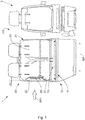
- FIGS. 1 to 3 Embodiments of a seat assembly 1 for a motor vehicle according to the invention will be described.
- the seat assembly 1 is designed as a double passenger seat of a trained as a transporter motor vehicle (not fully shown) and arranged in a fixed position together with a driver's seat assembly 2 in a passenger compartment FR of the transporter.
- the seat assembly comprises a seat 10, a backrest 20, a side airbag device 30 and a sensor device 40 (see Fig. 3 ) on.
- the seat 10 has a preferably metallic seat structure (with a support frame) 11 for providing structural dimensions and structural strength for seated seating of two persons (not shown) and a seat cushion 14 applied to at least one seating surface portion 13 of the seat structure 11 so as to form a seat 15 for the two persons (when seated).
- the backrest 20 has a preferably metallic seat back structure (with a support frame) 21 for providing structural dimensions and structural strength for rear support of the two persons (when seated) and a seat back padding 24 applied to at least a landing surface portion 23 of the seat back structure 21; so that it forms a leaning surface 25 for the two persons (when sitting taken).
- the side airbag device 30 is integrated into the backrest 20 adjacent to a lateral backrest boundary 26. More specifically, the side airbag device 30 is integrated with the seat back 20 so as to be offset toward a center 20a of the seatback 20 in a widthwise direction BR of the seat assembly 1, as opposed to a preferably metallic side wall 22 of the seatback 21 corresponding to the lateral seatback 26, and in the width direction BR (as seen by a sight BR1 in FIG Fig. 1 indicated arrow) is overlapped by the side cheek 22 on the side of the lateral backrest limitation 26.
- the side cheek 22 seen in the width direction BR of the seat assembly 1 (according to the direction indicated by the arrow BR1) have a width such that the side cheek 22 completely covers the Soairbag issued 30 on the side of the side backrest 26 limitation.
- the side airbag device 30 is fastened to the backrest structure 21 via a holder 31 connected thereto and is preferably arranged in the width direction BR of the seat arrangement 1 at a predetermined distance A1 (eg 20 mm to 30 mm) from the side wall 22 of the backrest structure 21.
- A1 eg 20 mm to 30 mm
- the sensor device 40 of the seat assembly 1 is adapted to detect when a person located on the seat assembly 1 has a seam-shaped gas cushion exit region 32 formed adjacent the backrest 20 adjacent the backrest 20 (see the dashed line in FIG Fig. 2 ) of the side airbag device 30 overlapping and outputting an overlap signal, the sensor device 40 being operatively connected to the side airbag device 30 so that the side airbag device 30 is deactivated upon the output of the overlap signal.
- the functional connection of the sensor device 40 with the side airbag device 30 is preferably realized via an electronic control device (not shown) for the side airbag device 30 and associated electrical lines (also not shown).
- the sensor device 40 is preferably adjacent to a side seat limiter 16 corresponding to the lateral backrest limiter 26 (see FIG Figures 2 and 3 ) integrated into the seat 10.
- the sensor device 40 preferably engages in the seat upholstery 14 as a pressure sensor device, so that the sensor device 40 in a width direction BR of the seat arrangement 1 having a predetermined width (eg 20 mm to 40 mm) has a pressure load recognize the seat cushion 14 and can output the overlap signal upon detection of such a pressure load.
- the seat padding 14 as edge region has a bead 14a which exceeds the seat surface 15, wherein the sensor device 40 engages the bead 14a, so that the sensor device 40 can detect a pressure load on the bead 14a and output the overlap signal upon detection of a pressure load on the bead 14a ,
- the sensor device 40 may include a first pressure sensor 41 which engages the bead 14a so as to detect a pressure load acting on the bead 14a from the seat 15 obliquely from above and generate a first detection signal upon detection of such pressure load; a second pressure sensor 42 which engages the bead 14a so as to detect a compressive load acting vertically from above on the bead 14a and to generate a second detection signal upon detection of such pressure load.
- the sensor device 40 is configured to output the overlap signal based on the second detection signal.
- the overlap signal may be output when the second detection signal is present.
- a warning signal is generated and made perceptible by a visual output device (e.g., warning lamp) and / or a sound producing output device (e.g., a buzzer) to the passengers in the passenger compartment.
- a visual output device e.g., warning lamp
- a sound producing output device e.g., a buzzer
- a protective function provided by the side airbag device 30 for a person in the passenger compartment FR on the seat arrangement 1 is more reliably ensured against side impact injuries.
- the side airbag device 30 as described above, it is possible to prevent gas cushion deployment-related injuries to a person on the seat arrangement 1.
Landscapes
- Engineering & Computer Science (AREA)
- Mechanical Engineering (AREA)
- Aviation & Aerospace Engineering (AREA)
- Transportation (AREA)
- Computer Networks & Wireless Communication (AREA)
- Air Bags (AREA)
- Seats For Vehicles (AREA)
Claims (10)
- Système de siège (1) pour un véhicule automobile, présentant:un siège (10), qui possède une structure de siège (11) destinée à offrir des dimensions de structure et une solidité de structure permettant d'accueillir au moins une personne en position assise ainsi qu'un rembourrage de siège (14), qui est placé au moins sur une partie de surface d'assise (13) de la structure de siège (11), de telle manière qu'il forme une surface d'assise (15) pour ladite au moins une personne,un dossier (20), qui possède une structure de dossier (21) destinée à offrir des dimensions de structure et une solidité de structure permettant d'assurer un appui dorsal à ladite au moins une personne ainsi qu'un rembourrage de dossier (24), qui est placé au moins sur une partie de surface de dossier (23) de la structure de dossier (21), de telle manière qu'il forme une surface d'appui (25) pour ladite au moins une personne, etun système de coussin gonflable latéral (30), qui est intégré dans le dossier (20) à proximité d'un bord latéral de dossier (26), dans lequel le système de coussin gonflable latéral (30) est intégré dans le dossier (20) de telle manière qu'il soit décalé en direction d'un milieu (20a) du dossier (20) dans une direction de largeur (BR) du système de siège (1) par rapport à une joue latérale (22) de la structure de dossier (21) correspondant au bord latéral de dossier (26) et que, vu dans la direction de largeur (BR), il soit recouvert par la joue latérale (22) du côté du bord latéral de dossier (26),caractérisé en ce quele rembourrage de siège (14) présente comme zone de bord un bourrelet (14a) dépassant en hauteur la surface d'assise (15), etle système de siège présente un dispositif de capteurs (40), avec un premier capteur de pression (41), qui s'engage dans le bourrelet (14a) de telle manière qu'il puisse détecter une charge de pression agissant à partir de la surface d'assise (15) en oblique par le haut sur le bourrelet (14a) et émettre un premier signal de détection en cas de détection d'une telle charge de pression, et avec un deuxième capteur de pression (42), qui s'engage dans le bourrelet (14a) de telle manière qu'il détectent une charge de pression agissant verticalement de haut en bas sur le bourrelet (14a) et qu'il produise un deuxième signal de détection en cas de détection d'une telle charge de pression, dans lequel un signal d'avertissement est produit au moyen du premier signal de détection par le dispositif de commande électronique, auquel le dispositif de capteurs 30 est connecté et est perceptible par les personnes présentes dans l'habitacle (FR) au moyen d'un dispositif d'émission visuelle et/ou d'un dispositif d'émission acoustique, eten cas de présence du deuxième signal de détection, celui-ci est reconnu par le dispositif de commande électronique comme signal de recouvrement et un signal de désactivation est envoyé au système de coussin gonflable latéral par le dispositif de commande électronique sur la base d'un signal de recouvrement, lorsqu'une personne se trouvant sur le système de siège (1) recouvre une zone de sortie de coussin de gaz (32) du système de coussin gonflable latéral (30) en forme de couture réalisée sur le dossier (20) à proximité du bord latéral de coussin gonflable (26).
- Système de siège (1) selon la revendication 1, dans lequel la joue latérale (22), vue dans la direction de largeur (BR) du système de siège (1), présente une largeur telle qu'elle recouvre entièrement le système de coussin gonflable latéral (30) du côté du bord latéral de dossier (26).
- Système de siège (1) selon la revendication 1 ou 2, dans lequel le système de coussin gonflable latéral (30) est disposé, dans la direction de largeur (BR) du système de siège (1), à une distance prédéterminée (A1) de la joue latérale (22) de la structure de dossier (21).
- Système de siège (1) selon l'une quelconque des revendications 1 à 3, dans lequel le système de siège (1) est configuré en forme de banquette pour un véhicule automobile constitué par une camionnette, dans lequel la structure de siège (11) est configurée de façon à offrir des dimensions de structure et une solidité de structure permettant d'accueillir plusieurs personnes en position assise, et dans lequel la structure de dossier (21) est configurée de façon à offrir des dimensions de structure et une solidité de structure permettant d'assurer un appui dorsal auxdites plusieurs personnes.
- Système de siège (1) selon la revendication 4, dans lequel la banquette de siège est configurée en forme de banquette double pour passager pour la camionnette, dans lequel la structure de siège (11) est configurée de façon à offrir des dimensions de structure et une solidité de structure permettant d'accueillir deux personnes en position assise, et dans lequel la structure de dossier (21) est configurée de façon à offrir des dimensions de structure et une solidité de structure permettant d'assurer un appui dorsal auxdites deux personnes.
- Système de siège (1) selon la revendication 5, avec un dispositif de capteurs (40), qui est conçu pour détecter lorsqu'une personne se trouvant sur le système de siège (1) recouvre une zone de sortie de coussin de gaz (32) du système de coussin gonflable (30) formée sur le dossier (20) à proximité du bord latéral de dossier (26), et en cas de recouvrement pour émettre un signal de recouvrement, dans lequel le dispositif de capteurs (40) est en liaison fonctionnelle avec le système de coussin gonflable latéral (30), de telle manière que le système de coussin gonflable latéral (30) soit désactivé lors de l'émission du signal de recouvrement.
- Système de siège (1) selon la revendication 6, dans lequel le dispositif de capteurs (40) est intégré dans le siège (10) à proximité d'un bord latéral de siège (16) correspondant au bord latéral de dossier (26).
- Système de siège (1) selon la revendication 7, dans lequel le dispositif de capteurs (40) réalisé sous forme de dispositif de capteurs de pression s'engage dans le rembourrage de siège (14), de telle manière que le dispositif de capteurs (40) puisse détecter une charge de pression sur le rembourrage de siège (14) dans une région de bord latéral présentant une largeur prédéterminée dans la direction de largeur (BR) du système de siège (1) et émettre le signal de recouvrement en cas de détection d'une telle charge de pression.
- Système de siège (1) selon la revendication 8, dans lequel le rembourrage de siège (14) présente comme zone de bord un bourrelet (14a) dépassant la surface d'assise (15), et dans lequel le dispositif de capteurs (40) s'engage dans le bourrelet (14a), de telle manière que le dispositif de capteurs (40) puisse détecter une charge de pression sur le bourrelet (14a) et émettre le signal de recouvrement en cas de détection d'une charge de pression sur le bourrelet (14a).
- Système de siège (1) selon la revendication 9, dans lequel le dispositif de capteurs (40) présente un premier capteur de pression (41), qui s'engage dans le bourrelet (14a) de telle manière qu'il puisse détecter une charge de pression agissant à partir de la surface d'assise (15) en oblique par le haut sur le bourrelet (14a) et émettre un premier signal de détection en cas de détection d'une telle charge de pression, et un deuxième capteur de pression (42), qui s'engage dans le bourrelet (14a) de telle manière qu'il puisse détecter une charge de pression agissant verticalement de haut en bas sur le bourrelet (14a) et produire un deuxième signal de détection en cas de détection d'une telle charge de pression, et dans lequel le dispositif de capteurs (40) est conçu pour émettre le signal de recouvrement sur la base d'au moins un du premier et du deuxième signal de détection.
Applications Claiming Priority (2)
| Application Number | Priority Date | Filing Date | Title |
|---|---|---|---|
| DE201310221657 DE102013221657A1 (de) | 2013-10-24 | 2013-10-24 | Sitzanordnung |
| PCT/EP2014/072613 WO2015059174A1 (fr) | 2013-10-24 | 2014-10-22 | Système de siège |
Publications (2)
| Publication Number | Publication Date |
|---|---|
| EP3060433A1 EP3060433A1 (fr) | 2016-08-31 |
| EP3060433B1 true EP3060433B1 (fr) | 2018-10-03 |
Family
ID=51753239
Family Applications (1)
| Application Number | Title | Priority Date | Filing Date |
|---|---|---|---|
| EP14786689.1A Active EP3060433B1 (fr) | 2013-10-24 | 2014-10-22 | Système de siège |
Country Status (4)
| Country | Link |
|---|---|
| EP (1) | EP3060433B1 (fr) |
| CN (1) | CN105473386B (fr) |
| DE (1) | DE102013221657A1 (fr) |
| WO (1) | WO2015059174A1 (fr) |
Families Citing this family (2)
| Publication number | Priority date | Publication date | Assignee | Title |
|---|---|---|---|---|
| DE102015215148A1 (de) | 2015-08-07 | 2017-02-09 | Bayerische Motoren Werke Aktiengesellschaft | Kraftfahrzeugsitz mit Anprallschutz sowie Kraftfahrzeug mit einem solchen Kraftfahrzeugsitz |
| CN106389069A (zh) * | 2016-11-09 | 2017-02-15 | 广东美的安川服务机器人有限公司 | 康复训练装置及康复训练装置的康复训练方法 |
Citations (1)
| Publication number | Priority date | Publication date | Assignee | Title |
|---|---|---|---|---|
| DE10018170A1 (de) * | 2000-04-12 | 2001-10-25 | Takata Europ Gmbh | Luftsackanordnung |
Family Cites Families (13)
| Publication number | Priority date | Publication date | Assignee | Title |
|---|---|---|---|---|
| DE19620537B4 (de) * | 1995-06-03 | 2006-10-12 | Volkswagen Ag | Airbag-Einrichtung |
| DE19820567A1 (de) * | 1998-05-08 | 1999-11-11 | Bayerische Motoren Werke Ag | Seitenaufprallschutz für Kraftfahrzeuge |
| DE19904071A1 (de) * | 1999-02-02 | 2000-08-03 | Volkswagen Ag | Sicherheitsvorrichtung für ein Kraftfahrzeug mit einem Airbag |
| US6578871B2 (en) * | 2001-10-09 | 2003-06-17 | Delphi Technologies, Inc. | Vehicle occupant weight detection system with occupant position compensation |
| CN102099227B (zh) * | 2008-07-15 | 2014-04-16 | 高田-彼得里公开股份有限公司 | 机动车辆的车辆座椅设备和气囊设备及保护车辆乘员的方法 |
| DE102009016888A1 (de) * | 2009-04-08 | 2010-10-14 | GM Global Technology Operations, Inc., Detroit | Seitenschutzairbaganordnung |
| DE102010027401B4 (de) * | 2010-07-15 | 2022-05-12 | Autoliv Development Ab | Seitengassack mit seitlicher Abstützung |
| KR20120050717A (ko) | 2010-11-11 | 2012-05-21 | 현대자동차주식회사 | 승객 이동용 에어백 장치, 승객 이동용 에어백 장치를 포함하는 사이드 에어백 시스템 및 그 제어 방법 |
| JP5904090B2 (ja) * | 2011-11-15 | 2016-04-13 | 豊田合成株式会社 | エアバッグ装置 |
| JP2013124028A (ja) * | 2011-12-15 | 2013-06-24 | Nhk Spring Co Ltd | 車両用シート |
| US8924086B2 (en) * | 2012-02-01 | 2014-12-30 | GM Global Technology Operations LLC | Method for control of seat mounted airbag in a seat with armrest |
| US20130200664A1 (en) * | 2012-02-07 | 2013-08-08 | Lear Corporation | Vehicle seat side air bag assemlby having strap secured air bag chute |
| US8876154B2 (en) * | 2012-03-30 | 2014-11-04 | Lear Corporation | Vehicle seat assembly having a back panel module |
-
2013
- 2013-10-24 DE DE201310221657 patent/DE102013221657A1/de not_active Withdrawn
-
2014
- 2014-10-22 WO PCT/EP2014/072613 patent/WO2015059174A1/fr not_active Ceased
- 2014-10-22 EP EP14786689.1A patent/EP3060433B1/fr active Active
- 2014-10-22 CN CN201480046912.0A patent/CN105473386B/zh active Active
Patent Citations (1)
| Publication number | Priority date | Publication date | Assignee | Title |
|---|---|---|---|---|
| DE10018170A1 (de) * | 2000-04-12 | 2001-10-25 | Takata Europ Gmbh | Luftsackanordnung |
Also Published As
| Publication number | Publication date |
|---|---|
| CN105473386A (zh) | 2016-04-06 |
| WO2015059174A1 (fr) | 2015-04-30 |
| EP3060433A1 (fr) | 2016-08-31 |
| CN105473386B (zh) | 2018-05-11 |
| DE102013221657A1 (de) | 2015-04-30 |
Similar Documents
| Publication | Publication Date | Title |
|---|---|---|
| DE102017103063B4 (de) | Insassenschutzvorrichtung | |
| DE19814678B4 (de) | Airbagsteuersystem für Beifahrersitze | |
| DE102012201932A1 (de) | Insassenschutzvorrichtung und Insassenschutzverfahren | |
| DE102012202471A1 (de) | Insassenschutzvorrichtung und Insassenschutzberfahren | |
| DE102015214729A1 (de) | Insassenschutzvorrichtung für ein Fahrzeug | |
| WO2008095615A1 (fr) | Airbag, module airbag et véhicule automobile | |
| DE10223366A1 (de) | Vorrichtung zur Erkennung eines Aufsassens eines motorisierten Zweirades | |
| DE102015202586A1 (de) | Sitzanordnung mit pyrotechnischer befestigung zum schutz von nicht angeschnallten fahrzeuginsassen | |
| DE102017103826A1 (de) | Fahrzeuginsassen-Rückhaltevorrichtung und Verfahren zum Betreiben einer Fahrzeuginsassen-Rückhaltevorrichtung | |
| DE60125745T2 (de) | Selbstzentrierender luftsack und herstellungsverfahren | |
| DE102010003315A1 (de) | Verfahren und Vorrichtung zum Schützen und Halten eines Insassen sowie eine Auswerte- und Steuereinheit für eine Schutz- und Haltevorrichtung | |
| DE102015116057A1 (de) | Insassenschutzvorrichtung für ein Fahrzeug | |
| EP1412232B1 (fr) | Systeme de retenue des passagers dans la zone des sieges arriere d'un vehicule automobile | |
| DE102020201840A1 (de) | Insassenschutzvorrichtung | |
| EP1632407B1 (fr) | Système de securite pour des personnes | |
| DE102019200813A1 (de) | Verfahren zum Betreiben eines Rückhaltesystems und Rückhaltesystem für ein Fahrzeug | |
| DE69905643T2 (de) | Seitenairbagmodul- Montagevorrichtung für einen Vordersitz eines Kraftfahrzeuges | |
| DE102007051282A1 (de) | Rückhaltesystem für ein Kraftfahrzeug | |
| EP3060433B1 (fr) | Système de siège | |
| DE102010054743B4 (de) | Sicherheitseinrichtung in einem Kraftfahrzeug | |
| EP1377486B1 (fr) | Dispositif pour avertir les occupants d'un vehicule | |
| DE202006020577U1 (de) | Baugruppe mit einer Instrumententafel für Kraftfahrzeuge und einem Kniegassack | |
| DE102018102436A1 (de) | Luftgurtvorrichtung für ein Fahrzeug | |
| DE102013217947A1 (de) | Verfahren, Vorrichtung und System zum Betreiben von Personenschutzmitteln | |
| DE102009016885A1 (de) | Airbagmodul und Fahrzeugsitz mit dem Airbagmodul |
Legal Events
| Date | Code | Title | Description |
|---|---|---|---|
| PUAI | Public reference made under article 153(3) epc to a published international application that has entered the european phase |
Free format text: ORIGINAL CODE: 0009012 |
|
| 17P | Request for examination filed |
Effective date: 20160524 |
|
| AK | Designated contracting states |
Kind code of ref document: A1 Designated state(s): AL AT BE BG CH CY CZ DE DK EE ES FI FR GB GR HR HU IE IS IT LI LT LU LV MC MK MT NL NO PL PT RO RS SE SI SK SM TR |
|
| AX | Request for extension of the european patent |
Extension state: BA ME |
|
| DAX | Request for extension of the european patent (deleted) | ||
| GRAP | Despatch of communication of intention to grant a patent |
Free format text: ORIGINAL CODE: EPIDOSNIGR1 |
|
| INTG | Intention to grant announced |
Effective date: 20180703 |
|
| GRAS | Grant fee paid |
Free format text: ORIGINAL CODE: EPIDOSNIGR3 |
|
| GRAA | (expected) grant |
Free format text: ORIGINAL CODE: 0009210 |
|
| AK | Designated contracting states |
Kind code of ref document: B1 Designated state(s): AL AT BE BG CH CY CZ DE DK EE ES FI FR GB GR HR HU IE IS IT LI LT LU LV MC MK MT NL NO PL PT RO RS SE SI SK SM TR |
|
| REG | Reference to a national code |
Ref country code: GB Ref legal event code: FG4D Free format text: NOT ENGLISH |
|
| REG | Reference to a national code |
Ref country code: CH Ref legal event code: EP Ref country code: AT Ref legal event code: REF Ref document number: 1048247 Country of ref document: AT Kind code of ref document: T Effective date: 20181015 |
|
| REG | Reference to a national code |
Ref country code: FR Ref legal event code: PLFP Year of fee payment: 5 |
|
| REG | Reference to a national code |
Ref country code: IE Ref legal event code: FG4D Free format text: LANGUAGE OF EP DOCUMENT: GERMAN Ref country code: DE Ref legal event code: R096 Ref document number: 502014009654 Country of ref document: DE |
|
| REG | Reference to a national code |
Ref country code: NL Ref legal event code: MP Effective date: 20181003 |
|
| REG | Reference to a national code |
Ref country code: LT Ref legal event code: MG4D |
|
| PG25 | Lapsed in a contracting state [announced via postgrant information from national office to epo] |
Ref country code: NL Free format text: LAPSE BECAUSE OF FAILURE TO SUBMIT A TRANSLATION OF THE DESCRIPTION OR TO PAY THE FEE WITHIN THE PRESCRIBED TIME-LIMIT Effective date: 20181003 |
|
| PG25 | Lapsed in a contracting state [announced via postgrant information from national office to epo] |
Ref country code: PL Free format text: LAPSE BECAUSE OF FAILURE TO SUBMIT A TRANSLATION OF THE DESCRIPTION OR TO PAY THE FEE WITHIN THE PRESCRIBED TIME-LIMIT Effective date: 20181003 Ref country code: LT Free format text: LAPSE BECAUSE OF FAILURE TO SUBMIT A TRANSLATION OF THE DESCRIPTION OR TO PAY THE FEE WITHIN THE PRESCRIBED TIME-LIMIT Effective date: 20181003 Ref country code: HR Free format text: LAPSE BECAUSE OF FAILURE TO SUBMIT A TRANSLATION OF THE DESCRIPTION OR TO PAY THE FEE WITHIN THE PRESCRIBED TIME-LIMIT Effective date: 20181003 Ref country code: NO Free format text: LAPSE BECAUSE OF FAILURE TO SUBMIT A TRANSLATION OF THE DESCRIPTION OR TO PAY THE FEE WITHIN THE PRESCRIBED TIME-LIMIT Effective date: 20190103 Ref country code: BG Free format text: LAPSE BECAUSE OF FAILURE TO SUBMIT A TRANSLATION OF THE DESCRIPTION OR TO PAY THE FEE WITHIN THE PRESCRIBED TIME-LIMIT Effective date: 20190103 Ref country code: LV Free format text: LAPSE BECAUSE OF FAILURE TO SUBMIT A TRANSLATION OF THE DESCRIPTION OR TO PAY THE FEE WITHIN THE PRESCRIBED TIME-LIMIT Effective date: 20181003 Ref country code: FI Free format text: LAPSE BECAUSE OF FAILURE TO SUBMIT A TRANSLATION OF THE DESCRIPTION OR TO PAY THE FEE WITHIN THE PRESCRIBED TIME-LIMIT Effective date: 20181003 Ref country code: IS Free format text: LAPSE BECAUSE OF FAILURE TO SUBMIT A TRANSLATION OF THE DESCRIPTION OR TO PAY THE FEE WITHIN THE PRESCRIBED TIME-LIMIT Effective date: 20190203 Ref country code: CZ Free format text: LAPSE BECAUSE OF FAILURE TO SUBMIT A TRANSLATION OF THE DESCRIPTION OR TO PAY THE FEE WITHIN THE PRESCRIBED TIME-LIMIT Effective date: 20181003 Ref country code: ES Free format text: LAPSE BECAUSE OF FAILURE TO SUBMIT A TRANSLATION OF THE DESCRIPTION OR TO PAY THE FEE WITHIN THE PRESCRIBED TIME-LIMIT Effective date: 20181003 |
|
| PG25 | Lapsed in a contracting state [announced via postgrant information from national office to epo] |
Ref country code: GR Free format text: LAPSE BECAUSE OF FAILURE TO SUBMIT A TRANSLATION OF THE DESCRIPTION OR TO PAY THE FEE WITHIN THE PRESCRIBED TIME-LIMIT Effective date: 20190104 Ref country code: PT Free format text: LAPSE BECAUSE OF FAILURE TO SUBMIT A TRANSLATION OF THE DESCRIPTION OR TO PAY THE FEE WITHIN THE PRESCRIBED TIME-LIMIT Effective date: 20190203 Ref country code: RS Free format text: LAPSE BECAUSE OF FAILURE TO SUBMIT A TRANSLATION OF THE DESCRIPTION OR TO PAY THE FEE WITHIN THE PRESCRIBED TIME-LIMIT Effective date: 20181003 Ref country code: SE Free format text: LAPSE BECAUSE OF FAILURE TO SUBMIT A TRANSLATION OF THE DESCRIPTION OR TO PAY THE FEE WITHIN THE PRESCRIBED TIME-LIMIT Effective date: 20181003 Ref country code: AL Free format text: LAPSE BECAUSE OF FAILURE TO SUBMIT A TRANSLATION OF THE DESCRIPTION OR TO PAY THE FEE WITHIN THE PRESCRIBED TIME-LIMIT Effective date: 20181003 |
|
| REG | Reference to a national code |
Ref country code: CH Ref legal event code: PL |
|
| REG | Reference to a national code |
Ref country code: BE Ref legal event code: MM Effective date: 20181031 |
|
| PG25 | Lapsed in a contracting state [announced via postgrant information from national office to epo] |
Ref country code: LU Free format text: LAPSE BECAUSE OF NON-PAYMENT OF DUE FEES Effective date: 20181022 |
|
| REG | Reference to a national code |
Ref country code: DE Ref legal event code: R097 Ref document number: 502014009654 Country of ref document: DE |
|
| REG | Reference to a national code |
Ref country code: IE Ref legal event code: MM4A |
|
| PG25 | Lapsed in a contracting state [announced via postgrant information from national office to epo] |
Ref country code: DK Free format text: LAPSE BECAUSE OF FAILURE TO SUBMIT A TRANSLATION OF THE DESCRIPTION OR TO PAY THE FEE WITHIN THE PRESCRIBED TIME-LIMIT Effective date: 20181003 |
|
| PLBE | No opposition filed within time limit |
Free format text: ORIGINAL CODE: 0009261 |
|
| STAA | Information on the status of an ep patent application or granted ep patent |
Free format text: STATUS: NO OPPOSITION FILED WITHIN TIME LIMIT |
|
| PG25 | Lapsed in a contracting state [announced via postgrant information from national office to epo] |
Ref country code: MC Free format text: LAPSE BECAUSE OF FAILURE TO SUBMIT A TRANSLATION OF THE DESCRIPTION OR TO PAY THE FEE WITHIN THE PRESCRIBED TIME-LIMIT Effective date: 20181003 Ref country code: LI Free format text: LAPSE BECAUSE OF NON-PAYMENT OF DUE FEES Effective date: 20181031 Ref country code: CH Free format text: LAPSE BECAUSE OF NON-PAYMENT OF DUE FEES Effective date: 20181031 Ref country code: SM Free format text: LAPSE BECAUSE OF FAILURE TO SUBMIT A TRANSLATION OF THE DESCRIPTION OR TO PAY THE FEE WITHIN THE PRESCRIBED TIME-LIMIT Effective date: 20181003 Ref country code: SK Free format text: LAPSE BECAUSE OF FAILURE TO SUBMIT A TRANSLATION OF THE DESCRIPTION OR TO PAY THE FEE WITHIN THE PRESCRIBED TIME-LIMIT Effective date: 20181003 Ref country code: EE Free format text: LAPSE BECAUSE OF FAILURE TO SUBMIT A TRANSLATION OF THE DESCRIPTION OR TO PAY THE FEE WITHIN THE PRESCRIBED TIME-LIMIT Effective date: 20181003 Ref country code: RO Free format text: LAPSE BECAUSE OF FAILURE TO SUBMIT A TRANSLATION OF THE DESCRIPTION OR TO PAY THE FEE WITHIN THE PRESCRIBED TIME-LIMIT Effective date: 20181003 Ref country code: BE Free format text: LAPSE BECAUSE OF NON-PAYMENT OF DUE FEES Effective date: 20181031 |
|
| 26N | No opposition filed |
Effective date: 20190704 |
|
| PG25 | Lapsed in a contracting state [announced via postgrant information from national office to epo] |
Ref country code: SI Free format text: LAPSE BECAUSE OF FAILURE TO SUBMIT A TRANSLATION OF THE DESCRIPTION OR TO PAY THE FEE WITHIN THE PRESCRIBED TIME-LIMIT Effective date: 20181003 Ref country code: IE Free format text: LAPSE BECAUSE OF NON-PAYMENT OF DUE FEES Effective date: 20181022 |
|
| PG25 | Lapsed in a contracting state [announced via postgrant information from national office to epo] |
Ref country code: MT Free format text: LAPSE BECAUSE OF FAILURE TO SUBMIT A TRANSLATION OF THE DESCRIPTION OR TO PAY THE FEE WITHIN THE PRESCRIBED TIME-LIMIT Effective date: 20181003 |
|
| PGFP | Annual fee paid to national office [announced via postgrant information from national office to epo] |
Ref country code: IT Payment date: 20191024 Year of fee payment: 6 |
|
| PG25 | Lapsed in a contracting state [announced via postgrant information from national office to epo] |
Ref country code: TR Free format text: LAPSE BECAUSE OF FAILURE TO SUBMIT A TRANSLATION OF THE DESCRIPTION OR TO PAY THE FEE WITHIN THE PRESCRIBED TIME-LIMIT Effective date: 20181003 |
|
| PGFP | Annual fee paid to national office [announced via postgrant information from national office to epo] |
Ref country code: GB Payment date: 20191029 Year of fee payment: 6 |
|
| PG25 | Lapsed in a contracting state [announced via postgrant information from national office to epo] |
Ref country code: MK Free format text: LAPSE BECAUSE OF NON-PAYMENT OF DUE FEES Effective date: 20181003 Ref country code: HU Free format text: LAPSE BECAUSE OF FAILURE TO SUBMIT A TRANSLATION OF THE DESCRIPTION OR TO PAY THE FEE WITHIN THE PRESCRIBED TIME-LIMIT; INVALID AB INITIO Effective date: 20141022 Ref country code: CY Free format text: LAPSE BECAUSE OF FAILURE TO SUBMIT A TRANSLATION OF THE DESCRIPTION OR TO PAY THE FEE WITHIN THE PRESCRIBED TIME-LIMIT Effective date: 20181003 |
|
| REG | Reference to a national code |
Ref country code: AT Ref legal event code: MM01 Ref document number: 1048247 Country of ref document: AT Kind code of ref document: T Effective date: 20191022 |
|
| PG25 | Lapsed in a contracting state [announced via postgrant information from national office to epo] |
Ref country code: AT Free format text: LAPSE BECAUSE OF NON-PAYMENT OF DUE FEES Effective date: 20191022 |
|
| GBPC | Gb: european patent ceased through non-payment of renewal fee |
Effective date: 20201022 |
|
| PG25 | Lapsed in a contracting state [announced via postgrant information from national office to epo] |
Ref country code: GB Free format text: LAPSE BECAUSE OF NON-PAYMENT OF DUE FEES Effective date: 20201022 |
|
| PG25 | Lapsed in a contracting state [announced via postgrant information from national office to epo] |
Ref country code: IT Free format text: LAPSE BECAUSE OF NON-PAYMENT OF DUE FEES Effective date: 20201022 |
|
| PGFP | Annual fee paid to national office [announced via postgrant information from national office to epo] |
Ref country code: FR Payment date: 20221024 Year of fee payment: 9 |
|
| P01 | Opt-out of the competence of the unified patent court (upc) registered |
Effective date: 20230523 |
|
| PG25 | Lapsed in a contracting state [announced via postgrant information from national office to epo] |
Ref country code: FR Free format text: LAPSE BECAUSE OF NON-PAYMENT OF DUE FEES Effective date: 20231031 |
|
| PGFP | Annual fee paid to national office [announced via postgrant information from national office to epo] |
Ref country code: DE Payment date: 20251031 Year of fee payment: 12 |