EP3060741B1 - Bohrvorrichtung - Google Patents
Bohrvorrichtung Download PDFInfo
- Publication number
- EP3060741B1 EP3060741B1 EP14856522.9A EP14856522A EP3060741B1 EP 3060741 B1 EP3060741 B1 EP 3060741B1 EP 14856522 A EP14856522 A EP 14856522A EP 3060741 B1 EP3060741 B1 EP 3060741B1
- Authority
- EP
- European Patent Office
- Prior art keywords
- drilling
- guide
- drill bit
- drilling device
- arrangement
- Prior art date
- Legal status (The legal status is an assumption and is not a legal conclusion. Google has not performed a legal analysis and makes no representation as to the accuracy of the status listed.)
- Active
Links
Images



Classifications
-
- E—FIXED CONSTRUCTIONS
- E21—EARTH OR ROCK DRILLING; MINING
- E21B—EARTH OR ROCK DRILLING; OBTAINING OIL, GAS, WATER, SOLUBLE OR MELTABLE MATERIALS OR A SLURRY OF MINERALS FROM WELLS
- E21B10/00—Drill bits
- E21B10/26—Drill bits with leading portion, i.e. drill bits with a pilot cutter; Drill bits for enlarging the borehole, e.g. reamers
- E21B10/32—Drill bits with leading portion, i.e. drill bits with a pilot cutter; Drill bits for enlarging the borehole, e.g. reamers with expansible cutting tools
-
- E—FIXED CONSTRUCTIONS
- E21—EARTH OR ROCK DRILLING; MINING
- E21B—EARTH OR ROCK DRILLING; OBTAINING OIL, GAS, WATER, SOLUBLE OR MELTABLE MATERIALS OR A SLURRY OF MINERALS FROM WELLS
- E21B10/00—Drill bits
- E21B10/36—Percussion drill bits
-
- E—FIXED CONSTRUCTIONS
- E21—EARTH OR ROCK DRILLING; MINING
- E21B—EARTH OR ROCK DRILLING; OBTAINING OIL, GAS, WATER, SOLUBLE OR MELTABLE MATERIALS OR A SLURRY OF MINERALS FROM WELLS
- E21B10/00—Drill bits
- E21B10/62—Drill bits characterised by parts, e.g. cutting elements, which are detachable or adjustable
-
- E—FIXED CONSTRUCTIONS
- E21—EARTH OR ROCK DRILLING; MINING
- E21B—EARTH OR ROCK DRILLING; OBTAINING OIL, GAS, WATER, SOLUBLE OR MELTABLE MATERIALS OR A SLURRY OF MINERALS FROM WELLS
- E21B10/00—Drill bits
- E21B10/62—Drill bits characterised by parts, e.g. cutting elements, which are detachable or adjustable
- E21B10/627—Drill bits characterised by parts, e.g. cutting elements, which are detachable or adjustable with plural detachable cutting elements
- E21B10/633—Drill bits characterised by parts, e.g. cutting elements, which are detachable or adjustable with plural detachable cutting elements independently detachable
-
- E—FIXED CONSTRUCTIONS
- E21—EARTH OR ROCK DRILLING; MINING
- E21B—EARTH OR ROCK DRILLING; OBTAINING OIL, GAS, WATER, SOLUBLE OR MELTABLE MATERIALS OR A SLURRY OF MINERALS FROM WELLS
- E21B7/00—Special methods or apparatus for drilling
- E21B7/20—Driving or forcing casings or pipes into boreholes, e.g. sinking; Simultaneously drilling and casing boreholes
-
- E—FIXED CONSTRUCTIONS
- E21—EARTH OR ROCK DRILLING; MINING
- E21B—EARTH OR ROCK DRILLING; OBTAINING OIL, GAS, WATER, SOLUBLE OR MELTABLE MATERIALS OR A SLURRY OF MINERALS FROM WELLS
- E21B10/00—Drill bits
- E21B10/64—Drill bits characterised by the whole or part thereof being insertable into or removable from the borehole without withdrawing the drilling pipe
Definitions
- the disclosure relates to a drilling device that is meant to be used in a down-the-hole drilling apparatus for drilling a hole by using the drilling device and a casing part as well as a hammering device when needed.
- the drilling device comprises in a drilling head thereof a guide, drilling means as well as advantageously flushing means for flushing of drilling waste being generated.
- the drilling means comprise a first drill bit arrangement and a second drill bit arrangement that is movable with respect to the above, whereby the drill bit arrangements are provided with drilling organs, such as an integrated drilling part, separate drilling pieces, bits or the like.
- the second drill bit arrangement is arranged on the one hand to be expanded for drilling a greater hole than a free cross-sectional surface area of an end of the casing part and on the other hand to be reduced to a smaller size than the free cross-sectional surface area of the end of the casing part in order to make possible removal of the drilling device from a hole that has been drilled and for leaving the casing part in the drilled hole by removing the drilling device through the casing part from above.
- the second drill bit arrangement is arranged by two or more bit pieces that are movable in radial direction on the drilling surface of the drilling means, and in which the drilling organs are arranged when viewed in longitudinal direction of the drilling device on the front surface thereof.
- a boring tool which is meant for boring and/or hammer drilling, to be used in connection with a drill rod unit placed inside a core pipe.
- the boring tool to be attached at the front end of the drill rod unit has a center drill, being provided with a cutting unit, and an eccentric reaming drill, being placed behind the center drill, the reaming drill having also a cutting unit.
- the reaming drill moves with respect to the center drill between a drilling position, in which it is positioned to the side in front of the core pipe, and a return position, in which it is withdrawn in radial direction inside the core pipe.
- the center drill is in most cases provided with four cutting parts directed radially and being made of hard metal
- the reamer for its part comprising either one or two radially directed cutting parts made of hard metal
- the cutting parts are replaced by bit parts being arranged in a certain manner.
- the bit blocks are arranged movable in respect with each other by coupling each one thereof by a single guiding pin with a guide part supporting the bit blocks, which pins depending on the rotation direction of the guide part bring about protrusion of the bit blocks or the same getting together in cooperation with guide grooves in the guide part.
- the second drill bit arrangement is arranged by two or more bit pieces that are movable in radial direction in slide grooves that pass wide open on the drilling surface of the drilling means, and, in which the drilling organs are arranged when viewed in longitudinal direction of the drilling device on the front surface thereof.
- the slide grooves therein being inclined towards the drilling head of the drilling device when viewed in a longitudinal cross section, whereby the said bit pieces are arranged movable in the slide grooves e.g.
- a problem of the type of drilling heads described above is the very strongly conical drilling surfaces, which is why wearing out of the bits takes place unevenly, whereby a part of the drill bits wear out prematurely.
- a further difficult problem in practice related to the type of implementations in question is the fact that by the solutions utilized therein returning of the bit pieces to the reduced position of the drilling head is practically uncertain, and is not even possible under all circumstances, which is why the drilling head can necessarily not be removed from a drilled hole without getting broken.
- the type of drilling device in question may "get stuck", which requires reciprocating use in order to get the drill bit released, which causes the same problems that have been explained above about the use of eccentrical drills. Due to the above, with the types of implementations in question, it is not possible to carry out drilling in practice in an adequately reliable and long-lasting manner.
- bit pieces of the second drill bit arrangement are movable by means of a guide for expanding size of the second drill bit arrangement by moving its bit pieces in a radial direction outwards, by rotating the guide in a first direction, and for reducing the size of the second drill bit arrangement by moving its bit pieces in the radial direction inwards, by rotating the guide in an opposite direction with respect to the first direction.
- the bit pieces of the second drill bit arrangement are movable in wide open slide grooves in the radial direction on a drilling surface of the drilling means.
- the drilling device according the present disclosure is aimed to achieve a decisive improvement in the problems described above and thus to raise substantially the level of prior art. To bring about this aim, the drilling device according to the invention is characterized by what has been defined in the claims.
- the bit pieces of the second drill bit arrangement of the drilling means are arranged movable from an expanded drilling position to a reduced position and vice versa in radially directed slide grooves on the drilling surface, first of all by influence of the rotation movement of the guide and on the other hand by a "forced control" achieved by a movement mechanism controlling the movement of the bit pieces.
- the slide grooves mentioned above are carried out furthermore advantageously e.g. by a so called dovetile or t-groove in a way that movement of the drill pieces in other directions is totally prevented.
- the risk for breakage of the drilling device is low also thanks to the fact that a significantly lower fatigue stress is directed thereto due to drilling when compared to utilization of solutions based on one single drill bit or in other ways asymmetrical solutions.
- the overall cost effectiveness of the drilling device according to the disclosure is based also on the fact that the structure of the drilling device's back part may be carried out clearly lighter than the same of the corresponding present solutions. What is the most important, is the fact that the drilling device according to the disclosure also makes possible removal of the drilling device from inside the casing part as a whole with its movable parts as one single piece from above, in which case there is no need to leave anything extra in addition to the casing part or the core pipe in the hole that has been drilled. The above has naturally a remarkable cost savings effect.
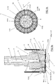
- the disclosure relates to a drilling device that is meant to be used in a down-the-hole drilling apparatus for drilling a hole by using the drilling device 1 and a casing part 2 as well as a hammering device when needed.
- the drilling device 1 comprises in the drilling head I thereof a guide 4, drilling means 5 as well as advantageously flushing means for flushing of drilling waste being generated.
- the drilling means 5 comprise a first drill bit arrangement 5a and a second drill bit arrangement 5b that is movable with respect to the above, whereby the drill bit arrangements are provided with drilling organs 10, such as an integrated drilling part, separate drilling pieces, bits or the like.
- the second drill bit arrangement is arranged on the one hand to be expanded for drilling a greater t hole than a free cross-sectional surface area of an end I' of the casing part 2 and on the other hand to be reduced to a smaller size than the free cross-sectional surface area of the end I' of the casing part in order to make possible removal of the drilling device from a hole that has been drilled and for leaving the casing part 2 in the drilled hole by removing the drilling device 1 through the casing part 2 from above.
- the second drill bit arrangement 5b is arranged by two or more bit pieces that are movable in radial direction r on a drilling surface P of the drilling means, and in which the drilling organs 10; 10" are arranged when viewed in a longitudinal direction s of the drilling device on the front surface thereof.
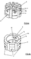
- the bit pieces 5b1 being advantageously essentially elongated that is essentially longer than the width of the slide grooves U and belonging to the second drill bit arrangement 5b, are arranged, for expanding/reducing of the second drill bit arrangement 5b by means of the guide 4, movable in slide grooves U that pass wide open in the radial direction r on the drilling surface P of the drilling means 5 for expanding the second drill bit arrangement 5b by moving its bit pieces 5b1 in the radial direction r outwards in the slide grooves U, by rotating the guide 4 in one direction w in the drilling direction, and for reducing the second drill bit arrangement 5b by moving its bit pieces 5b1 in the radial direction inwards in the slide grooves U, by rotating the guide 4 in an opposite direction.
- the first drill bit arrangement 5a is arranged in an immovable manner in connection with the guide 4, whereby as a furthermore advantageous embodiment, the drilling organs 10' of the first drill bit arrangement 5a, being arranged in a built-in manner in the guide 4, are arranged at an outer end of the guide 4 operating as the drilling surface P1.
- the slide grooves U of the bit pieces 5b1 of the second drill bit arrangement 5b are arranged in an auxiliary frame R1 according to figure 2a , which is coupled with the guide 4 on the principle that manifests itself in figure 1a to rotate in a restricted manner in a crosswise plane x, such as by a pin/guide groove arrangement T1/O1 or a like.
- a movement mechanism of the bit pieces 5b; 5b1 of the second drill bit arrangement, moving in the radial direction r in a crosswise plane x that is essentially to the longitudinal direction of the drilling device, is arranged depending on the rotation direction of the guide 4 to push the guide in the longitudinal direction s out from the casing part 2 or to pull the same inside the casing part 2, whereby the movements of the bit pieces in the radial direction r are arranged by influence of a guide surface arrangement y', being in connection with the bit pieces and both the casing part 2 and an end of the guide 4.
- the guide surface arrangement y' mentioned above comprises for example in the embodiment according to figure 1a an edge gasket at the outer edge of the guide 4 as well as e.g. according to figure 2b inclined guide surfaces at the opposite ends of the bit pieces 5b1, which glide against an internal guide surface of the casing shoe 8 existing at the end of the casing part 2, when the guide 4 moves in the longitudinal direction s inside the casing part 2 as explained in the following.
- the embodiment according to figures 1a, 1b is carried out furthermore advantageously in a way that the bits 10' at the end of the guide 4 are positioned in the longitudinal direction s to some extent deeper than the bits 10" of the second drill bit arrangement 5, which has been found in practice to operate more profitably in drilling in some occasions than by placing the bits in totally the same plane.
- the bits 10" at opposite ends of the bit pieces 5b1 are placed advantageously on inclined surfaces and so that the bits at the "reaming end" of the bit pieces are arranged to ream the drill being drilled according to figure 1 with an adequate clearance t with respect to the outer diameter of the casing shoe 8 at the end of the casing part 8.
- movement z of the guide 4 in the longitudinal direction s while the same is being rotated in an opposite direction with respect to the drilling rotation direction w is arranged by a thread coupling carried out by a pin/guide groove arrangement T1/O1 or a like between the guide 4 and the auxiliary frame R1, in which case the auxiliary frame has one or more thread grooves and the guide 4 has respectively one or more draw pins.
- the thread coupling in question which is carried out advantageously by using draw pins to be installed in holes H in the auxiliary frame R1 after installation of the guide 4 and the auxiliary frame R1 on top of each other, works in practice in a drilling situation also as a power transmission arrangement transmitting the guide's 4 rotational motion to the auxiliary frame R1.
- the first drill bit arrangement 5a is arranged in an intermediate frame R2, which is coupled with the guide 4 to be movable with a restricted rotational movement in a crosswise plane x, such as by a pin/guide groove arrangement T2/O2 or a like that manifests itself in figures 3a and 4b .
- the above manifests itself in figure 4b , in which the intermediate frame R2 is shown from behind, according to which in the hole H in the intermediate frame R2 is fitted a pin T2 that moves in an elongated guide groove O2 in the guide 4.
- bit pieces 5b; 5b1 of the second drill bit arrangement that are movable in the crosswise plane x, as shown in figure 3b that is essentially perpendicular to the longitudinal direction s of the drilling device, are further advantageously coupled with slide grooves U, such as so called dovetail or T-grooves, in the intermediate frame R2 that comprises the drilling organs 10' of the first drill bit arrangement 5a, which grooves hold the bit pieces also axially s (which principle applies naturally also to the bit pieces of the embodiment according to figures 1a, 1b ).
- slide grooves U such as so called dovetail or T-grooves
- the movement of the drill bits 5b; 5b1 of the second drill bit arrangement in the radial direction r are arranged by a movement mechanism between the guide 4 and the bit pieces 5b1.
- the movement mechanism in question is arranged by a mutual pin/glide groove arrangement T3/O3 between an end surface 4a of the guide 4 and back surfaces of the bit pieces 5b1 or in a corresponding manner, wherein with reference particularly to figures 5a and 5b , the movement mechanism has been carried out in this case by guide grooves O3 at the end surface of the guide 4, which depending on the rotating direction of the guide 4 transmit the bit pieces' 5b1 movement in radial direction in the slide grooves U in co-operation with pins T3 in the bit pieces.
Landscapes
- Engineering & Computer Science (AREA)
- Life Sciences & Earth Sciences (AREA)
- Geology (AREA)
- Mining & Mineral Resources (AREA)
- Physics & Mathematics (AREA)
- Environmental & Geological Engineering (AREA)
- Fluid Mechanics (AREA)
- General Life Sciences & Earth Sciences (AREA)
- Geochemistry & Mineralogy (AREA)
- Mechanical Engineering (AREA)
- Earth Drilling (AREA)
Claims (8)
- Bohrvorrichtung, die in einem Imlochbohrgerät zum Bohren eines Lochs unter Verwendung der Bohrvorrichtung (1) und eines Mantelteils (2) verwendet werden soll, wobei die Bohrvorrichtung (1) aus einem Bohrkopf (I) mit einer Führung (4) und Bohrmitteln (5) besteht, wobei die Bohrmittel (5) eine erste Bohrmeißelanordnung (5a) und eine zweite Bohrmeißelanordnung (5b) umfassen, die zueinander beweglich sind, wobei die Bohrmeißelanordnungen mit Bohrorganen (10), wie einem integrierten Bohrteil, separaten Bohrstücken oder -meißeln, versehen sind, wobei die Weite der zweiten Bohrmeißelanordnung einerseits zum Bohren eines (t) Lochs, das größer als eine freie Querschnittsfläche eines Endes (I') des Mantelteils (2) ist, aufgespannt werden kann und andererseits auf eine kleinere Weite als die freie Querschnittsfläche des Endes (I') des Mantelteils verkleinert werden kann, um es möglich zu machen, die Bohrvorrichtung aus einem gebohrten Loch zu entfernen und das Mantelteil (2) durch Entfernen der Bohrvorrichtung (1) durch das Mantelteil (2) von oben in dem Bohrloch zu belassen, wobei die zweite Bohrmeißelanordnung (5b) aus Bohrstücken (5b1), die in weit geöffneten Gleitnuten (U) in radialer Richtung (r) auf einer Bohrfläche (P) der Bohrmittel (5) beweglich sind, den Bohrorganen (10; 10") der Bohrmittel, die in Längsrichtung (s) der Bohrvorrichtung gesehen auf ihrer Vorderfläche angeordnet sind, besteht, wobei die Bohrvorrichtung einen Bewegungsmechanismus zum Bewegen der Bohrstücke (5b1) mittels der Führung (4) zum Aufspannen der Weite der zweiten Bohrmeißelanordnung (5b) durch Bewegen ihrer Bohrstücke (5b1) in radialer Richtung (r) in den Gleitnuten (U) nach außen durch Drehen der Führung (4) in eine erste Richtung (w) und zum Verkleinern der Weite der zweiten Bohrmeißelanordnung (5b) durch Bewegen ihrer Bohrstücke (5b1) in radialer Richtung nach innen in den Gleitnuten (U) durch Drehen der Führung (4) in entgegengesetzter Richtung in Bezug auf die erste Richtung (w), umfasst, dadurch gekennzeichnet, dass die Bohrvorrichtung einen Hilfsrahmen (R1) umfasst, dessen Bohrfläche (P2) mit mehreren Gleitnuten (U) mit den Bohrstücken (5b1) der zweiten Bohrmeißelanordnung (5b) versehen ist, wobei der Hilfsrahmen mit einer in einer senkrechten Ebene (x) in Bezug auf die Längsrichtung (s) begrenzt drehbaren Stift/Führungsnut-Anordnung (T1/O1) zwischen der Führung (4) und dem Hilfsrahmen (R1) mit der Führung (4) verbunden ist, wobei der Bewegungsmechanismus zum Bewegen der Bohrstücke (5b; 5b1), der die Führung abhängig von der Drehrichtung der Führung (4) in Längsrichtung (s) aus dem Mantelteil (2) herausschiebt oder diese in das Mantelteil (2) hineinzieht, eine Führungsflächenanordnung (y') mit geneigten Führungsflächen in den Bohrstücken und sowohl im Mantelteil (2) als auch an einem Ende der Führung (4) umfasst.
- Bohrvorrichtung nach Anspruch 1, dadurch gekennzeichnet, dass der Bewegungsmechanismus für die Bewegung (z) der Führung (4) in Längsrichtung (s), während diese gedreht wird, eine Gewindekupplung umfasst, die von der Stift/Führungsnut-Anordnung (T1/O1) zwischen der Führung (4) und dem Hilfsrahmen (R1) realisiert wird, beispielsweise durch eine oder mehrere Gewinde-Nuten im Hilfsrahmen und einen oder mehrere Zugbolzen in der Führung (4).
- Bohrvorrichtung nach einem der vorstehenden Ansprüche, dadurch gekennzeichnet, dass die erste Bohrmeißelanordnung (5a) in Verbindung mit der Führung (4) unbeweglich angeordnet ist.
- Bohrvorrichtung nach einem der vorstehenden Ansprüche, dadurch gekennzeichnet, dass die Bohrorgane (10') der ersten Bohrmeißelanordnung (5a) an einem äußeren Ende der Führung (4) angeordnet sind und als ein Teil (P1) der Bohrfläche (P) der Bohrmittel fungieren.
- Bohrvorrichtung, die in einem Imlochbohrgerät zum Bohren eines Lochs unter Verwendung der Bohrvorrichtung (1) und eines Mantelteils (2) verwendet werden soll, wobei die Bohrvorrichtung (1) aus einem Bohrkopf (I) mit einer Führung (4) und Bohrmitteln (5) besteht, wobei die Bohrmittel (5) eine erste Bohrmeißelanordnung (5a) und eine zweite Bohrmeißelanordnung (5b) umfassen, die zueinander beweglich sind, wobei die Bohrmeißelanordnungen mit Bohrorganen (10), wie einem integrierten Bohrteil, separaten Bohrstücken oder -meißeln, versehen sind, wobei die Weite der zweiten Bohrmeißelanordnung einerseits zum Bohren eines (t) Lochs, das größer als eine freie Querschnittsfläche eines Endes (I') des Mantelteils (2) ist, aufgespannt werden kann und andererseits auf eine kleinere Weite als die freie Querschnittsfläche des Endes (I') des Mantelteils verkleinert werden kann, um es möglich zu machen, die Bohrvorrichtung aus einem gebohrten Loch zu entfernen und das Mantelteil (2) durch Entfernen der Bohrvorrichtung (1) durch das Mantelteil (2) von oben in dem Bohrloch zu belassen, wobei die zweite Bohrmeißelanordnung (5b) aus Bohrstücken (5b1), die in weit geöffneten Gleitnuten (U) in radialer Richtung (r) auf einer Bohrfläche (P) der Bohrmittel (5) beweglich sind, den Bohrorganen (10; 10") der Bohrmittel, die in Längsrichtung (s) der Bohrvorrichtung gesehen auf ihrer Vorderfläche angeordnet sind, besteht, wobei die Bohrvorrichtung einen Bewegungsmechanismus zum Bewegen der Bohrstücke (5b1) mittels der Führung (4) zum Aufspannen der Weite der zweiten Bohrmeißelanordnung (5b) durch Bewegen ihrer Bohrstücke (5b1) in radialer Richtung (r) in den Gleitnuten (U) nach außen durch Drehen der Führung (4) in eine erste Richtung (w) und zum Verkleinern der Weite der zweiten Bohrmeißelanordnung (5b) durch Bewegen ihrer Bohrstücke (5b1) in radialer Richtung nach innen in den Gleitnuten (U) durch Drehen der Führung (4) in entgegengesetzter Richtung in Bezug auf die erste Richtung (w), umfasst, dadurch gekennzeichnet, dass die Bohrvorrichtung einen Zwischenrahmen (R2) umfasst, dessen Bohrfläche (P1) mit mehreren Gleitnuten (U) mit den Bohrstücken (5b1) der zweiten Bohrmeißelanordnung (5b) versehen ist, wobei der Zwischenrahmen mit einer in einer senkrechten Ebene (x) in Bezug auf die Längsrichtung (s) begrenzt drehbaren Stift/Führungsnut-Anordnung (T2/O2) zwischen der Führung (4) und dem Zwischenrahmen (R2) mit der Führung (4) verbunden ist, wobei der Bewegungsmechanismus zum Bewegen der Bohrstücke (5b; 5b1) einsatzbereit zwischen der Führung (4) und den Bohrstücken (5b1) angeordnet ist und aus einer beidseitigen Stift/Gleitnut-Anordnung (T3/O3) auf einer Endfläche (4a) der Führung (4) und auf den rückseitigen Flächen der Bohrstücke (5b1) besteht.
- Bohrvorrichtung nach Anspruch 5, dadurch gekennzeichnet, dass der Zwischenrahmen (R2) auf seiner Bohrfläche (P1) die Bohrorgane (10') der ersten Bohranordnung (5a) umfasst.
- Bohrvorrichtung nach einem der vorstehenden Ansprüche, dadurch gekennzeichnet, dass sie eine Hammervorrichtung umfasst.
- Bohrvorrichtung nach einem der vorhergehenden Ansprüche, dadurch gekennzeichnet, dass sie Spülmittel (6) zum Spülen von anfallenden Bohrabfällen umfasst.
Applications Claiming Priority (2)
| Application Number | Priority Date | Filing Date | Title |
|---|---|---|---|
| FI20136041A FI124451B (fi) | 2013-10-22 | 2013-10-22 | Porauslaite |
| PCT/FI2014/050546 WO2015059347A1 (en) | 2013-10-22 | 2014-07-02 | Drilling device |
Publications (3)
| Publication Number | Publication Date |
|---|---|
| EP3060741A1 EP3060741A1 (de) | 2016-08-31 |
| EP3060741A4 EP3060741A4 (de) | 2017-06-14 |
| EP3060741B1 true EP3060741B1 (de) | 2019-09-04 |
Family
ID=51494612
Family Applications (1)
| Application Number | Title | Priority Date | Filing Date |
|---|---|---|---|
| EP14856522.9A Active EP3060741B1 (de) | 2013-10-22 | 2014-07-02 | Bohrvorrichtung |
Country Status (6)
| Country | Link |
|---|---|
| US (1) | US10024108B2 (de) |
| EP (1) | EP3060741B1 (de) |
| KR (1) | KR102251002B1 (de) |
| CA (1) | CA2927247C (de) |
| FI (1) | FI124451B (de) |
| WO (1) | WO2015059347A1 (de) |
Families Citing this family (6)
| Publication number | Priority date | Publication date | Assignee | Title |
|---|---|---|---|---|
| FI127402B (fi) * | 2015-09-14 | 2018-05-15 | Mincon Nordic Oy | Poralaite |
| EP3555410A4 (de) * | 2016-12-19 | 2020-08-26 | Flexidrill Limited | Hybridbohrmeissel |
| CN110869581B (zh) | 2017-05-31 | 2022-04-01 | 斯伦贝谢技术有限公司 | 具有预成形硬面堆焊部段的切割工具 |
| FI130094B (en) | 2019-08-26 | 2023-01-31 | Mincon Nordic Oy | Boring unit |
| KR102172162B1 (ko) | 2020-06-01 | 2020-10-30 | 전재운 | Rcd용 슬라이딩 확공 비트구조체 |
| US12031386B2 (en) | 2020-08-27 | 2024-07-09 | Schlumberger Technology Corporation | Blade cover |
Family Cites Families (15)
| Publication number | Priority date | Publication date | Assignee | Title |
|---|---|---|---|---|
| GB973790A (en) | 1962-07-17 | 1964-10-28 | Jerome Labrosse | Drill assembly |
| US3365010A (en) | 1966-01-24 | 1968-01-23 | Tri State Oil Tools Inc | Expandable drill bit |
| CH622312A5 (en) | 1977-09-30 | 1981-03-31 | Anton Broder | Drill bit, in particular for drilling in overburden |
| SE421551B (sv) | 1980-03-26 | 1982-01-04 | Sandvik Ab | Borrverktyg for rotations- och/eller slagborrning |
| AU644195B2 (en) | 1990-07-27 | 1993-12-02 | Mitsubishi Materials Corporation | Excavation tool |
| US5361859A (en) | 1993-02-12 | 1994-11-08 | Baker Hughes Incorporated | Expandable gage bit for drilling and method of drilling |
| JP3322484B2 (ja) | 1994-07-22 | 2002-09-09 | 知勇 重盛 | ボーリング等用の削進ビット |
| JP2998097B2 (ja) | 1996-02-13 | 2000-01-11 | 株式会社利根 | 拡径ビット |
| US5957226A (en) | 1997-01-28 | 1999-09-28 | Holte; Ardis L. | Reverse circulation drilling system with hexagonal pipe coupling |
| KR100685386B1 (ko) * | 2004-09-03 | 2007-02-22 | 임병덕 | 인-라인 확장 윙을 갖는 시추공 굴착장치 및 그 구동방법 |
| JP4957440B2 (ja) * | 2007-08-06 | 2012-06-20 | 三菱マテリアル株式会社 | 掘削工具 |
| JP5135962B2 (ja) * | 2007-09-11 | 2013-02-06 | 三菱マテリアル株式会社 | 掘削工具、掘削ビット及びデバイス |
| FI20095046A0 (fi) * | 2009-01-21 | 2009-01-21 | Atlas Copco Rotex Ab Oy | Menetelmä ja laitteisto uppoporaukseen |
| JP5396937B2 (ja) * | 2009-03-13 | 2014-01-22 | 三菱マテリアル株式会社 | 掘削工具 |
| US8230951B2 (en) * | 2009-09-30 | 2012-07-31 | Baker Hughes Incorporated | Earth-boring tools having expandable members and methods of making and using such earth-boring tools |
-
2013
- 2013-10-22 FI FI20136041A patent/FI124451B/fi active IP Right Grant
-
2014
- 2014-07-02 KR KR1020167009723A patent/KR102251002B1/ko active Active
- 2014-07-02 US US15/030,461 patent/US10024108B2/en active Active
- 2014-07-02 CA CA2927247A patent/CA2927247C/en active Active
- 2014-07-02 WO PCT/FI2014/050546 patent/WO2015059347A1/en not_active Ceased
- 2014-07-02 EP EP14856522.9A patent/EP3060741B1/de active Active
Non-Patent Citations (1)
| Title |
|---|
| None * |
Also Published As
| Publication number | Publication date |
|---|---|
| KR102251002B1 (ko) | 2021-05-12 |
| FI124451B (fi) | 2014-09-15 |
| CA2927247C (en) | 2020-02-25 |
| FI20136041A7 (fi) | 2014-09-15 |
| KR20160099530A (ko) | 2016-08-22 |
| EP3060741A1 (de) | 2016-08-31 |
| EP3060741A4 (de) | 2017-06-14 |
| CA2927247A1 (en) | 2015-04-30 |
| WO2015059347A1 (en) | 2015-04-30 |
| US20160281435A1 (en) | 2016-09-29 |
| US10024108B2 (en) | 2018-07-17 |
Similar Documents
| Publication | Publication Date | Title |
|---|---|---|
| EP3060741B1 (de) | Bohrvorrichtung | |
| EP1910640B1 (de) | Bohrmeisselanordnung für fluidbetätigte schlagbohrwerkzeuge | |
| US7461706B2 (en) | Drilling apparatus with percussive action cutter | |
| EP2917457B1 (de) | Sitzende hammervorrichtung für kernprobennahmen | |
| US9745800B2 (en) | Expandable reamers having nonlinearly expandable blades, and related methods | |
| WO2012039630A1 (en) | Hybrid drill bit | |
| CN113631793A (zh) | 用于冲击钻凿的岩钻头 | |
| US20160258221A1 (en) | Expandable Diameter Drill Bit | |
| CA3158682A1 (en) | Drill bit for boring earth and other hard materials | |
| US9611701B2 (en) | Method and apparatus for plastic pipe drilling | |
| EP2603659B1 (de) | Aufsatz für schlagbohrmaschinen | |
| US20160201400A1 (en) | Flow through gauge for drill bit | |
| AU2008100136A4 (en) | A Drill Bit Assembly for Fluid-Operated Percussion Drill Tools | |
| EP2300682A1 (de) | Verfahren und bohrvorrichtung zum bohren | |
| RU2385405C1 (ru) | Буровое шарошечное долото | |
| KR20080038309A (ko) | 유체 작동식 충격 드릴 공구용 드릴 비트 어셈블리 | |
| EP3433463B1 (de) | Abwärtsbohrvorrichtung | |
| RU2507362C1 (ru) | Расширитель раздвижной | |
| CN121877456A (zh) | 一种岩土取样装置及方法 | |
| WO2013108127A2 (en) | Hammer improvements | |
| IES85756Y1 (en) | An attachment for percussion drill tools |
Legal Events
| Date | Code | Title | Description |
|---|---|---|---|
| PUAI | Public reference made under article 153(3) epc to a published international application that has entered the european phase |
Free format text: ORIGINAL CODE: 0009012 |
|
| 17P | Request for examination filed |
Effective date: 20160512 |
|
| AK | Designated contracting states |
Kind code of ref document: A1 Designated state(s): AL AT BE BG CH CY CZ DE DK EE ES FI FR GB GR HR HU IE IS IT LI LT LU LV MC MK MT NL NO PL PT RO RS SE SI SK SM TR |
|
| AX | Request for extension of the european patent |
Extension state: BA ME |
|
| DAX | Request for extension of the european patent (deleted) | ||
| REG | Reference to a national code |
Ref country code: DE Ref legal event code: R079 Ref document number: 602014053170 Country of ref document: DE Free format text: PREVIOUS MAIN CLASS: E21B0010320000 Ipc: E21B0007200000 |
|
| A4 | Supplementary search report drawn up and despatched |
Effective date: 20170512 |
|
| RIC1 | Information provided on ipc code assigned before grant |
Ipc: E21B 10/32 20060101ALI20170505BHEP Ipc: E21B 7/20 20060101AFI20170505BHEP Ipc: E21B 10/36 20060101ALI20170505BHEP Ipc: E21B 10/633 20060101ALI20170505BHEP |
|
| RAP1 | Party data changed (applicant data changed or rights of an application transferred) |
Owner name: OY EPIROC DRILLING TOOLS AB |
|
| STAA | Information on the status of an ep patent application or granted ep patent |
Free format text: STATUS: EXAMINATION IS IN PROGRESS |
|
| 17Q | First examination report despatched |
Effective date: 20180214 |
|
| GRAP | Despatch of communication of intention to grant a patent |
Free format text: ORIGINAL CODE: EPIDOSNIGR1 |
|
| STAA | Information on the status of an ep patent application or granted ep patent |
Free format text: STATUS: GRANT OF PATENT IS INTENDED |
|
| INTG | Intention to grant announced |
Effective date: 20190506 |
|
| GRAS | Grant fee paid |
Free format text: ORIGINAL CODE: EPIDOSNIGR3 |
|
| GRAA | (expected) grant |
Free format text: ORIGINAL CODE: 0009210 |
|
| STAA | Information on the status of an ep patent application or granted ep patent |
Free format text: STATUS: THE PATENT HAS BEEN GRANTED |
|
| AK | Designated contracting states |
Kind code of ref document: B1 Designated state(s): AL AT BE BG CH CY CZ DE DK EE ES FI FR GB GR HR HU IE IS IT LI LT LU LV MC MK MT NL NO PL PT RO RS SE SI SK SM TR |
|
| REG | Reference to a national code |
Ref country code: GB Ref legal event code: FG4D |
|
| REG | Reference to a national code |
Ref country code: CH Ref legal event code: EP |
|
| REG | Reference to a national code |
Ref country code: AT Ref legal event code: REF Ref document number: 1175586 Country of ref document: AT Kind code of ref document: T Effective date: 20190915 |
|
| REG | Reference to a national code |
Ref country code: DE Ref legal event code: R096 Ref document number: 602014053170 Country of ref document: DE |
|
| REG | Reference to a national code |
Ref country code: IE Ref legal event code: FG4D |
|
| REG | Reference to a national code |
Ref country code: NO Ref legal event code: T2 Effective date: 20190904 |
|
| REG | Reference to a national code |
Ref country code: SE Ref legal event code: TRGR |
|
| REG | Reference to a national code |
Ref country code: NL Ref legal event code: MP Effective date: 20190904 |
|
| REG | Reference to a national code |
Ref country code: LT Ref legal event code: MG4D |
|
| PG25 | Lapsed in a contracting state [announced via postgrant information from national office to epo] |
Ref country code: HR Free format text: LAPSE BECAUSE OF FAILURE TO SUBMIT A TRANSLATION OF THE DESCRIPTION OR TO PAY THE FEE WITHIN THE PRESCRIBED TIME-LIMIT Effective date: 20190904 Ref country code: BG Free format text: LAPSE BECAUSE OF FAILURE TO SUBMIT A TRANSLATION OF THE DESCRIPTION OR TO PAY THE FEE WITHIN THE PRESCRIBED TIME-LIMIT Effective date: 20191204 Ref country code: FI Free format text: LAPSE BECAUSE OF FAILURE TO SUBMIT A TRANSLATION OF THE DESCRIPTION OR TO PAY THE FEE WITHIN THE PRESCRIBED TIME-LIMIT Effective date: 20190904 Ref country code: LT Free format text: LAPSE BECAUSE OF FAILURE TO SUBMIT A TRANSLATION OF THE DESCRIPTION OR TO PAY THE FEE WITHIN THE PRESCRIBED TIME-LIMIT Effective date: 20190904 |
|
| PG25 | Lapsed in a contracting state [announced via postgrant information from national office to epo] |
Ref country code: RS Free format text: LAPSE BECAUSE OF FAILURE TO SUBMIT A TRANSLATION OF THE DESCRIPTION OR TO PAY THE FEE WITHIN THE PRESCRIBED TIME-LIMIT Effective date: 20190904 Ref country code: GR Free format text: LAPSE BECAUSE OF FAILURE TO SUBMIT A TRANSLATION OF THE DESCRIPTION OR TO PAY THE FEE WITHIN THE PRESCRIBED TIME-LIMIT Effective date: 20191205 Ref country code: AL Free format text: LAPSE BECAUSE OF FAILURE TO SUBMIT A TRANSLATION OF THE DESCRIPTION OR TO PAY THE FEE WITHIN THE PRESCRIBED TIME-LIMIT Effective date: 20190904 Ref country code: LV Free format text: LAPSE BECAUSE OF FAILURE TO SUBMIT A TRANSLATION OF THE DESCRIPTION OR TO PAY THE FEE WITHIN THE PRESCRIBED TIME-LIMIT Effective date: 20190904 Ref country code: ES Free format text: LAPSE BECAUSE OF FAILURE TO SUBMIT A TRANSLATION OF THE DESCRIPTION OR TO PAY THE FEE WITHIN THE PRESCRIBED TIME-LIMIT Effective date: 20190904 |
|
| REG | Reference to a national code |
Ref country code: AT Ref legal event code: MK05 Ref document number: 1175586 Country of ref document: AT Kind code of ref document: T Effective date: 20190904 |
|
| REG | Reference to a national code |
Ref country code: DE Ref legal event code: R082 Ref document number: 602014053170 Country of ref document: DE Representative=s name: PUSCHMANN BORCHERT BARDEHLE PATENTANWAELTE PAR, DE Ref country code: DE Ref legal event code: R081 Ref document number: 602014053170 Country of ref document: DE Owner name: TERRAROC FINLAND OY, FI Free format text: FORMER OWNER: OY EPIROC DRILLING TOOLS AB, TAMPERE, FI Ref country code: DE Ref legal event code: R082 Ref document number: 602014053170 Country of ref document: DE Representative=s name: PUSCHMANN BORCHERT KAISER KLETTNER PATENTANWAE, DE |
|
| REG | Reference to a national code |
Ref country code: NO Ref legal event code: CHAD Owner name: TERRAROC FINLAND OY, FI |
|
| RAP2 | Party data changed (patent owner data changed or rights of a patent transferred) |
Owner name: TERRAROC FINLAND OY |
|
| PG25 | Lapsed in a contracting state [announced via postgrant information from national office to epo] |
Ref country code: NL Free format text: LAPSE BECAUSE OF FAILURE TO SUBMIT A TRANSLATION OF THE DESCRIPTION OR TO PAY THE FEE WITHIN THE PRESCRIBED TIME-LIMIT Effective date: 20190904 Ref country code: PL Free format text: LAPSE BECAUSE OF FAILURE TO SUBMIT A TRANSLATION OF THE DESCRIPTION OR TO PAY THE FEE WITHIN THE PRESCRIBED TIME-LIMIT Effective date: 20190904 Ref country code: PT Free format text: LAPSE BECAUSE OF FAILURE TO SUBMIT A TRANSLATION OF THE DESCRIPTION OR TO PAY THE FEE WITHIN THE PRESCRIBED TIME-LIMIT Effective date: 20200106 Ref country code: RO Free format text: LAPSE BECAUSE OF FAILURE TO SUBMIT A TRANSLATION OF THE DESCRIPTION OR TO PAY THE FEE WITHIN THE PRESCRIBED TIME-LIMIT Effective date: 20190904 Ref country code: EE Free format text: LAPSE BECAUSE OF FAILURE TO SUBMIT A TRANSLATION OF THE DESCRIPTION OR TO PAY THE FEE WITHIN THE PRESCRIBED TIME-LIMIT Effective date: 20190904 Ref country code: AT Free format text: LAPSE BECAUSE OF FAILURE TO SUBMIT A TRANSLATION OF THE DESCRIPTION OR TO PAY THE FEE WITHIN THE PRESCRIBED TIME-LIMIT Effective date: 20190904 |
|
| PG25 | Lapsed in a contracting state [announced via postgrant information from national office to epo] |
Ref country code: IS Free format text: LAPSE BECAUSE OF FAILURE TO SUBMIT A TRANSLATION OF THE DESCRIPTION OR TO PAY THE FEE WITHIN THE PRESCRIBED TIME-LIMIT Effective date: 20200224 Ref country code: SM Free format text: LAPSE BECAUSE OF FAILURE TO SUBMIT A TRANSLATION OF THE DESCRIPTION OR TO PAY THE FEE WITHIN THE PRESCRIBED TIME-LIMIT Effective date: 20190904 Ref country code: CZ Free format text: LAPSE BECAUSE OF FAILURE TO SUBMIT A TRANSLATION OF THE DESCRIPTION OR TO PAY THE FEE WITHIN THE PRESCRIBED TIME-LIMIT Effective date: 20190904 Ref country code: SK Free format text: LAPSE BECAUSE OF FAILURE TO SUBMIT A TRANSLATION OF THE DESCRIPTION OR TO PAY THE FEE WITHIN THE PRESCRIBED TIME-LIMIT Effective date: 20190904 |
|
| REG | Reference to a national code |
Ref country code: DE Ref legal event code: R097 Ref document number: 602014053170 Country of ref document: DE |
|
| PLBE | No opposition filed within time limit |
Free format text: ORIGINAL CODE: 0009261 |
|
| STAA | Information on the status of an ep patent application or granted ep patent |
Free format text: STATUS: NO OPPOSITION FILED WITHIN TIME LIMIT |
|
| PG2D | Information on lapse in contracting state deleted |
Ref country code: IS |
|
| PG25 | Lapsed in a contracting state [announced via postgrant information from national office to epo] |
Ref country code: DK Free format text: LAPSE BECAUSE OF FAILURE TO SUBMIT A TRANSLATION OF THE DESCRIPTION OR TO PAY THE FEE WITHIN THE PRESCRIBED TIME-LIMIT Effective date: 20190904 Ref country code: IS Free format text: LAPSE BECAUSE OF FAILURE TO SUBMIT A TRANSLATION OF THE DESCRIPTION OR TO PAY THE FEE WITHIN THE PRESCRIBED TIME-LIMIT Effective date: 20200105 |
|
| 26N | No opposition filed |
Effective date: 20200605 |
|
| PG25 | Lapsed in a contracting state [announced via postgrant information from national office to epo] |
Ref country code: SI Free format text: LAPSE BECAUSE OF FAILURE TO SUBMIT A TRANSLATION OF THE DESCRIPTION OR TO PAY THE FEE WITHIN THE PRESCRIBED TIME-LIMIT Effective date: 20190904 |
|
| PG25 | Lapsed in a contracting state [announced via postgrant information from national office to epo] |
Ref country code: MC Free format text: LAPSE BECAUSE OF FAILURE TO SUBMIT A TRANSLATION OF THE DESCRIPTION OR TO PAY THE FEE WITHIN THE PRESCRIBED TIME-LIMIT Effective date: 20190904 |
|
| REG | Reference to a national code |
Ref country code: CH Ref legal event code: PL |
|
| REG | Reference to a national code |
Ref country code: BE Ref legal event code: MM Effective date: 20200731 |
|
| PG25 | Lapsed in a contracting state [announced via postgrant information from national office to epo] |
Ref country code: CH Free format text: LAPSE BECAUSE OF NON-PAYMENT OF DUE FEES Effective date: 20200731 Ref country code: LU Free format text: LAPSE BECAUSE OF NON-PAYMENT OF DUE FEES Effective date: 20200702 Ref country code: LI Free format text: LAPSE BECAUSE OF NON-PAYMENT OF DUE FEES Effective date: 20200731 |
|
| PG25 | Lapsed in a contracting state [announced via postgrant information from national office to epo] |
Ref country code: BE Free format text: LAPSE BECAUSE OF NON-PAYMENT OF DUE FEES Effective date: 20200731 |
|
| PG25 | Lapsed in a contracting state [announced via postgrant information from national office to epo] |
Ref country code: MT Free format text: LAPSE BECAUSE OF FAILURE TO SUBMIT A TRANSLATION OF THE DESCRIPTION OR TO PAY THE FEE WITHIN THE PRESCRIBED TIME-LIMIT Effective date: 20190904 Ref country code: CY Free format text: LAPSE BECAUSE OF FAILURE TO SUBMIT A TRANSLATION OF THE DESCRIPTION OR TO PAY THE FEE WITHIN THE PRESCRIBED TIME-LIMIT Effective date: 20190904 |
|
| PG25 | Lapsed in a contracting state [announced via postgrant information from national office to epo] |
Ref country code: MK Free format text: LAPSE BECAUSE OF FAILURE TO SUBMIT A TRANSLATION OF THE DESCRIPTION OR TO PAY THE FEE WITHIN THE PRESCRIBED TIME-LIMIT Effective date: 20190904 |
|
| P01 | Opt-out of the competence of the unified patent court (upc) registered |
Effective date: 20230528 |
|
| REG | Reference to a national code |
Ref country code: GB Ref legal event code: 732E Free format text: REGISTERED BETWEEN 20240208 AND 20240214 |
|
| REG | Reference to a national code |
Ref country code: DE Ref legal event code: R081 Ref document number: 602014053170 Country of ref document: DE Owner name: TERRAROC FINLAND OY, FI Free format text: FORMER OWNER: TERRAROC FINLAND OY, TAMPERE, FI |
|
| PGFP | Annual fee paid to national office [announced via postgrant information from national office to epo] |
Ref country code: GB Payment date: 20250617 Year of fee payment: 12 |
|
| PGFP | Annual fee paid to national office [announced via postgrant information from national office to epo] |
Ref country code: NO Payment date: 20250619 Year of fee payment: 12 |
|
| PGFP | Annual fee paid to national office [announced via postgrant information from national office to epo] |
Ref country code: FR Payment date: 20250618 Year of fee payment: 12 |
|
| PGFP | Annual fee paid to national office [announced via postgrant information from national office to epo] |
Ref country code: TR Payment date: 20250617 Year of fee payment: 12 |
|
| PGFP | Annual fee paid to national office [announced via postgrant information from national office to epo] |
Ref country code: IE Payment date: 20250618 Year of fee payment: 12 |
|
| PGFP | Annual fee paid to national office [announced via postgrant information from national office to epo] |
Ref country code: SE Payment date: 20250618 Year of fee payment: 12 |
|
| PGFP | Annual fee paid to national office [announced via postgrant information from national office to epo] |
Ref country code: DE Payment date: 20250626 Year of fee payment: 12 |
|
| PGFP | Annual fee paid to national office [announced via postgrant information from national office to epo] |
Ref country code: IT Payment date: 20250704 Year of fee payment: 12 |