EP3061147B1 - Verfahren beim herunterfahren zur startvorbereitung eines brennstoffzellensystems - Google Patents
Verfahren beim herunterfahren zur startvorbereitung eines brennstoffzellensystems Download PDFInfo
- Publication number
- EP3061147B1 EP3061147B1 EP14792388.2A EP14792388A EP3061147B1 EP 3061147 B1 EP3061147 B1 EP 3061147B1 EP 14792388 A EP14792388 A EP 14792388A EP 3061147 B1 EP3061147 B1 EP 3061147B1
- Authority
- EP
- European Patent Office
- Prior art keywords
- fuel cell
- cell system
- measured values
- start preparation
- preparation routine
- Prior art date
- Legal status (The legal status is an assumption and is not a legal conclusion. Google has not performed a legal analysis and makes no representation as to the accuracy of the status listed.)
- Active
Links
Images
Classifications
-
- H—ELECTRICITY
- H01—ELECTRIC ELEMENTS
- H01M—PROCESSES OR MEANS, e.g. BATTERIES, FOR THE DIRECT CONVERSION OF CHEMICAL ENERGY INTO ELECTRICAL ENERGY
- H01M8/00—Fuel cells; Manufacture thereof
- H01M8/04—Auxiliary arrangements, e.g. for control of pressure or for circulation of fluids
- H01M8/04298—Processes for controlling fuel cells or fuel cell systems
- H01M8/043—Processes for controlling fuel cells or fuel cell systems applied during specific periods
- H01M8/04303—Processes for controlling fuel cells or fuel cell systems applied during specific periods applied during shut-down
-
- H—ELECTRICITY
- H01—ELECTRIC ELEMENTS
- H01M—PROCESSES OR MEANS, e.g. BATTERIES, FOR THE DIRECT CONVERSION OF CHEMICAL ENERGY INTO ELECTRICAL ENERGY
- H01M8/00—Fuel cells; Manufacture thereof
- H01M8/04—Auxiliary arrangements, e.g. for control of pressure or for circulation of fluids
- H01M8/04082—Arrangements for control of reactant parameters, e.g. pressure or concentration
- H01M8/04089—Arrangements for control of reactant parameters, e.g. pressure or concentration of gaseous reactants
- H01M8/04119—Arrangements for control of reactant parameters, e.g. pressure or concentration of gaseous reactants with simultaneous supply or evacuation of electrolyte; Humidifying or dehumidifying
- H01M8/04156—Arrangements for control of reactant parameters, e.g. pressure or concentration of gaseous reactants with simultaneous supply or evacuation of electrolyte; Humidifying or dehumidifying with product water removal
- H01M8/04179—Arrangements for control of reactant parameters, e.g. pressure or concentration of gaseous reactants with simultaneous supply or evacuation of electrolyte; Humidifying or dehumidifying with product water removal by purging or increasing flow or pressure of reactants
-
- H—ELECTRICITY
- H01—ELECTRIC ELEMENTS
- H01M—PROCESSES OR MEANS, e.g. BATTERIES, FOR THE DIRECT CONVERSION OF CHEMICAL ENERGY INTO ELECTRICAL ENERGY
- H01M8/00—Fuel cells; Manufacture thereof
- H01M8/04—Auxiliary arrangements, e.g. for control of pressure or for circulation of fluids
- H01M8/04223—Auxiliary arrangements, e.g. for control of pressure or for circulation of fluids during start-up or shut-down; Depolarisation or activation, e.g. purging; Means for short-circuiting defective fuel cells
- H01M8/04228—Auxiliary arrangements, e.g. for control of pressure or for circulation of fluids during start-up or shut-down; Depolarisation or activation, e.g. purging; Means for short-circuiting defective fuel cells during shut-down
-
- H—ELECTRICITY
- H01—ELECTRIC ELEMENTS
- H01M—PROCESSES OR MEANS, e.g. BATTERIES, FOR THE DIRECT CONVERSION OF CHEMICAL ENERGY INTO ELECTRICAL ENERGY
- H01M8/00—Fuel cells; Manufacture thereof
- H01M8/04—Auxiliary arrangements, e.g. for control of pressure or for circulation of fluids
- H01M8/04223—Auxiliary arrangements, e.g. for control of pressure or for circulation of fluids during start-up or shut-down; Depolarisation or activation, e.g. purging; Means for short-circuiting defective fuel cells
- H01M8/04231—Purging of the reactants
-
- H—ELECTRICITY
- H01—ELECTRIC ELEMENTS
- H01M—PROCESSES OR MEANS, e.g. BATTERIES, FOR THE DIRECT CONVERSION OF CHEMICAL ENERGY INTO ELECTRICAL ENERGY
- H01M8/00—Fuel cells; Manufacture thereof
- H01M8/04—Auxiliary arrangements, e.g. for control of pressure or for circulation of fluids
- H01M8/04223—Auxiliary arrangements, e.g. for control of pressure or for circulation of fluids during start-up or shut-down; Depolarisation or activation, e.g. purging; Means for short-circuiting defective fuel cells
- H01M8/04253—Means for solving freezing problems
-
- H—ELECTRICITY
- H01—ELECTRIC ELEMENTS
- H01M—PROCESSES OR MEANS, e.g. BATTERIES, FOR THE DIRECT CONVERSION OF CHEMICAL ENERGY INTO ELECTRICAL ENERGY
- H01M8/00—Fuel cells; Manufacture thereof
- H01M8/04—Auxiliary arrangements, e.g. for control of pressure or for circulation of fluids
- H01M8/04298—Processes for controlling fuel cells or fuel cell systems
- H01M8/04313—Processes for controlling fuel cells or fuel cell systems characterised by the detection or assessment of variables; characterised by the detection or assessment of failure or abnormal function
- H01M8/0432—Temperature; Ambient temperature
- H01M8/04358—Temperature; Ambient temperature of the coolant
-
- H—ELECTRICITY
- H01—ELECTRIC ELEMENTS
- H01M—PROCESSES OR MEANS, e.g. BATTERIES, FOR THE DIRECT CONVERSION OF CHEMICAL ENERGY INTO ELECTRICAL ENERGY
- H01M8/00—Fuel cells; Manufacture thereof
- H01M8/04—Auxiliary arrangements, e.g. for control of pressure or for circulation of fluids
- H01M8/04298—Processes for controlling fuel cells or fuel cell systems
- H01M8/04313—Processes for controlling fuel cells or fuel cell systems characterised by the detection or assessment of variables; characterised by the detection or assessment of failure or abnormal function
- H01M8/04537—Electric variables
- H01M8/04604—Power, energy, capacity or load
- H01M8/04619—Power, energy, capacity or load of fuel cell stacks
-
- H—ELECTRICITY
- H01—ELECTRIC ELEMENTS
- H01M—PROCESSES OR MEANS, e.g. BATTERIES, FOR THE DIRECT CONVERSION OF CHEMICAL ENERGY INTO ELECTRICAL ENERGY
- H01M8/00—Fuel cells; Manufacture thereof
- H01M8/04—Auxiliary arrangements, e.g. for control of pressure or for circulation of fluids
- H01M8/04298—Processes for controlling fuel cells or fuel cell systems
- H01M8/04694—Processes for controlling fuel cells or fuel cell systems characterised by variables to be controlled
- H01M8/04746—Pressure; Flow
- H01M8/04753—Pressure; Flow of fuel cell reactants
-
- H—ELECTRICITY
- H01—ELECTRIC ELEMENTS
- H01M—PROCESSES OR MEANS, e.g. BATTERIES, FOR THE DIRECT CONVERSION OF CHEMICAL ENERGY INTO ELECTRICAL ENERGY
- H01M2250/00—Fuel cells for particular applications; Specific features of fuel cell system
- H01M2250/20—Fuel cells in motive systems, e.g. vehicle, ship, plane
-
- Y—GENERAL TAGGING OF NEW TECHNOLOGICAL DEVELOPMENTS; GENERAL TAGGING OF CROSS-SECTIONAL TECHNOLOGIES SPANNING OVER SEVERAL SECTIONS OF THE IPC; TECHNICAL SUBJECTS COVERED BY FORMER USPC CROSS-REFERENCE ART COLLECTIONS [XRACs] AND DIGESTS
- Y02—TECHNOLOGIES OR APPLICATIONS FOR MITIGATION OR ADAPTATION AGAINST CLIMATE CHANGE
- Y02E—REDUCTION OF GREENHOUSE GAS [GHG] EMISSIONS, RELATED TO ENERGY GENERATION, TRANSMISSION OR DISTRIBUTION
- Y02E60/00—Enabling technologies; Technologies with a potential or indirect contribution to GHG emissions mitigation
- Y02E60/30—Hydrogen technology
- Y02E60/50—Fuel cells
-
- Y—GENERAL TAGGING OF NEW TECHNOLOGICAL DEVELOPMENTS; GENERAL TAGGING OF CROSS-SECTIONAL TECHNOLOGIES SPANNING OVER SEVERAL SECTIONS OF THE IPC; TECHNICAL SUBJECTS COVERED BY FORMER USPC CROSS-REFERENCE ART COLLECTIONS [XRACs] AND DIGESTS
- Y02—TECHNOLOGIES OR APPLICATIONS FOR MITIGATION OR ADAPTATION AGAINST CLIMATE CHANGE
- Y02T—CLIMATE CHANGE MITIGATION TECHNOLOGIES RELATED TO TRANSPORTATION
- Y02T90/00—Enabling technologies or technologies with a potential or indirect contribution to GHG emissions mitigation
- Y02T90/40—Application of hydrogen technology to transportation, e.g. using fuel cells
Definitions
- the invention relates to a method for preparing a fuel cell system for a starting process according to the closer defined in the preamble of claim 1.
- Fuel cell systems are known from the general state of the art. For example, they can be used in vehicles for providing electric drive power.
- One of the problems of fuel cell systems is the generation of very pure water in the fuel cell system during operation. If temperatures are now below freezing, which will inevitably occur in particular in vehicle applications, then the fuel cell system can freeze and then makes corresponding problems during a renewed starting process, or it takes a very long time until the fuel cell system can be started. This is because due to condensed and frozen moisture, for example, blocked gas ducts and / or valves and other components may be affected by the formation of ice in their function.
- a start preparation routine is carried out to discharge water and moisture from the fuel cell system.
- the fuel cell system is flushed with gas, which is conveyed for example by the air conveyor and / or a hydrogen circulation fan or another type of blower.
- gas which is conveyed for example by the air conveyor and / or a hydrogen circulation fan or another type of blower.
- the startup preparation routine will always proceed according to the same pattern by conveying a predetermined amount of gas, for example in air, through the fuel cell system to carry out moisture and blow out water.
- a predetermined amount of gas for example in air
- all gas conveyors are run at a constant speed for a fixed predetermined time.
- the amount is typically always designed so that a safe and reliable drying can be achieved in any case.
- the object of the present invention is now to provide a method for preparing a fuel cell system to a startup using a startup preparation routine, which works very simple and efficient and can be done very quickly, quietly and energy efficient.
- the start preparation routine is changed as a function of measured values in the fuel cell system. These measured values are recorded within a predetermined time interval before switching off the fuel cell system. Before switching off the fuel cell system, if this is still in operation, measured values can be detected very easily or are typically present anyway for specific control tasks and for influencing operating processes in the fuel cell system. These measurement values, which are available in any case, or the measurement values that are easy to record, can then be used to adapt the system preparation routine accordingly.
- the idea behind it is basically that, in a full load situation of the fuel cell system, for example, in a time interval of about 15 minutes before stopping the fuel cell system, much less moisture in the fuel cell system has remained because temperatures and flow rates are relatively high.
- a startup preparation routine will be completely omitted, or it will be performed in accordance with short or low rotational speeds of the gas delivery means for providing the air flow for drying the fuel cell system. This is energy efficient, fast and quiet. If it can be seen from the measured values recorded in the time interval before switching off the fuel cell system, however, that a partial load situation or an extreme low-load situation has occurred, then a much more humid fuel cell system is to be expected, so that the system preparation routine will be correspondingly longer and / or longer for careful drying of the fuel cell system. or is performed at higher speeds of the gas conveyor. In between there exists at least one intermediate stage.
- the measured values include cooling water temperatures in the fuel cell system.
- cooling water temperatures in the fuel cell system are very simple and efficiently to be detected values, which are indirectly related to the load requirements and directly with the situation with respect to the moisture, which is present after switching off the fuel cell system. For the acquisition of cooling water values, therefore, it is very easy and efficient to select a suitable start preparation routine.
- different cooling water temperature threshold values are specified, wherein the measured values include the time for which the cooling water temperature was above the respective cooling water temperature threshold value. For example, if the cooling water temperature within the last 15 minutes of operation of the fuel cell system to 80% above an upper cooling water temperature threshold, for example 60 ° C, then a much shorter system preparation routine can be performed, as if the cooling water temperature was only 10% above this upper cooling water temperature threshold and in the remaining time above a lower cooling water temperature threshold.
- the measured values are divided into individual classes depending on the load situation and / or the cooling water temperature of the fuel cell system within the time interval.
- Each of the classes is then a predetermined course of the System preparation routine assigned.
- Such a classification into classes can take place immediately when the fuel cell system is switched off.
- a division into five different classes take place, which are symbolic of full load, low load, low part load, medium part load and high part load.
- a suitable system preparation routine can then be carried out when the fuel cell system is switched off and, ideally, at a standstill conditioning, which optionally takes place later as a function of the temperature.
- the measured values or the classes into which the measured values are divided can be linked to the various system preparation routines via a characteristic map.
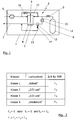
- a vehicle 1 very strongly schematized indicated.
- the vehicle 1 can be designed, for example, as a passenger car, truck, as a rail-bound vehicle or as a material handling vehicle for logistics purposes.
- the vehicle 1 could just as well be used as a ship or aircraft, for example.
- a principle indicated fuel cell system 2 the core of which forms a fuel cell 3.
- This fuel cell 3 should be constructed as a stack of individual PEM cells, as a so-called fuel cell stack or fuel cell stack.
- a cathode compartment 4 and an anode compartment 5 are indicated within the fuel cell 3.
- the cathode chamber 4 is supplied for regular operation air via an air conveyor 6 as an oxygen supplier.
- Exhaust air passes through an exhaust duct 7 from the fuel cell system 2.
- the anode compartment 5 of the fuel cell 3 is hydrogen a compressed gas storage 8 via a pressure regulating and metering unit 9 fed.
- Unconsumed hydrogen and inert gases and water, which arise in the region of the anode chamber 5, are returned via a recirculation line 10 and can be mixed with fresh hydrogen supplied to the anode chamber 5 again.
- a recirculation conveyor 11 is arranged, which is formed in the embodiment shown here as a hydrogen recirculation blower or HRB (Hydrogen Recirculation Blower).
- the recirculation conveyor 11 could just as well be realized as a gas jet pump or as a combination of a gas jet pump and a blower.
- a water separator 12 located in the recirculation line 10 is a water separator 12, which is connected via a discharge line 13 with a valve device 14 to the exhaust air line 7 from the fuel cell system 2.
- a valve device 14 located in the recirculation line 10 is also located in the recirculation line 10 .
- water separator 12 and the valve device 14 so water can be collected and drained, for example, from time to time. It is equally conceivable to discharge the water as a function of a fill level in the water separator or as a function of concentrations in the so-called anode cycle.
- connection line 15 with a valve device 16 connects the anode circuit with a supply air line 17 to the cathode compartment 4 of the fuel cell 3.
- a connection between the cathode side and the anode side of the fuel cell system 2 can thus be created when the valve device 16 is open.
- the connecting line 15 can also be used, for example, to discharge the gas in parallel with the discharge of water via the water separator 12 and the drain line 13, the branch point then typically being arranged between the water separator 12 and the recirculation conveyor 11.
- the introduction of the blown gas in the supply air line 17 is well known and customary, since so any hydrogen, which is typically always discharged in small quantities, on Catalyst of the cathode compartment 4 reacts and hydrogen emissions to the environment can be avoided.
- a startup preparation routine SVR which is carried out, for example, after the fuel cell system 2 has been switched off during shutdown, or which is carried out in the form of standstill conditioning, when temperatures in the surroundings of the vehicle 1 fall below a predetermined threshold, for example 3 ° C., is now carried out so that ideally the air conveyor 6 and the recirculation conveyor 11 are operated at a predetermined speed, for example with power from a battery, not shown here.
- a predetermined threshold for example 3 ° C.
- valve device 16 If the valve device 16 is then opened on the connecting line, the anode side is accordingly flushed through by the dry air, wherein ideally air and water are blown off via the water separator 12 and the water outlet line 13 when the valve device 14 is open. As a result, the fuel cell system 2 is dried accordingly and can be ideally prepared for a restart even if temperatures below freezing are present.
- the startup preparation routine regardless of whether it is performed when shutting down the fuel cell system after shutdown, or in the form of standstill conditioning, while the fuel cell system 2 or the vehicle 1 is not in operation, is always with the corresponding energy requirements for the air conveyor 6 and Rezirkulationsdorf adopted 11 connected and caused over the period t over which the startup preparation routine runs, a corresponding noise emission.
- a number of measured values can be recorded and stored in the fuel cell system 1 during operation. These measured values can be, for example, the load requirements of the fuel cell system 2 on the part of the vehicle 1. In particular, however, temperatures in the cooling water of the fuel cell system 2 can be detected.
- cooling water temperature threshold values are predetermined, for example two or three different threshold values in the temperature range which normally occurs during normal operation. Now it is so that during the operation of the fuel cell system 2 can be logged very easily and efficiently, for what periods of time Cooling water temperature is above the predetermined thresholds. If the fuel cell system 2 or the vehicle 1 is now switched off, then an evaluation of precisely these coded values can take place retroactively for a predetermined time interval before stopping, for example the last 15 minutes before stopping. As a result, a temperature profile and, associated therewith indirectly, a load profile of the fuel cell system 2 can be created.
- load states can be recognized in the individual rows of the table, at the top a full-load state, at the bottom a low-load state and in between two states which are intended to symbolize, for example, 1/3 load and 2/3 load.
- these values are evaluated and divided into the classes shown here, for example class 1 for full load and class 4 for low load.
- the time t 1 may thus either be 0 or be different from 0, but then is much smaller than the time t 4 of class 4, which corresponds to the low-load situation before switching off the fuel cell system 2.
- the times are staggered so that the time t 1 ⁇ t 2 ⁇ t 3 ⁇ t 4 .
- the same routine can be used.
- different routines for example with different times or in the case of standstill conditioning with correspondingly lower speeds in order to reduce the power requirement and the noise emissions.
- Different sequences of the start preparation routine SVR can also be assigned to the different classes, for example different pressure profiles or different times at which, for example, the valve devices 14, 16 are opened or closed.
Landscapes
- Life Sciences & Earth Sciences (AREA)
- Engineering & Computer Science (AREA)
- Manufacturing & Machinery (AREA)
- Sustainable Development (AREA)
- Sustainable Energy (AREA)
- Chemical & Material Sciences (AREA)
- Chemical Kinetics & Catalysis (AREA)
- Electrochemistry (AREA)
- General Chemical & Material Sciences (AREA)
- Fuel Cell (AREA)
Description
- Die Erfindung betrifft ein Verfahren zum Vorbereiten eines Brennstoffzellensystems auf einen Startvorgang nach der im Oberbegriff von Anspruch 1 näher definierten Art.
- Brennstoffzellensysteme sind aus dem allgemeinen Stand der Technik bekannt. Sie können beispielsweise in Fahrzeugen zur Bereitstellung von elektrischer Antriebsleistung eingesetzt werden. Eines der Probleme von Brennstoffzellensystemen liegt dabei in der Entstehung von sehr reinem Wasser in dem Brennstoffzellensystem während des Betriebs. Kommt es nun zu Temperaturen unterhalb des Gefrierpunkts, was insbesondere bei Fahrzeuganwendungen unvermeidbar auftreten wird, dann kann das Brennstoffzellensystem einfrieren und macht bei einem erneuten Startvorgang dann entsprechende Probleme beziehungsweise es benötigt sehr lange, bis das Brennstoffzellensystem gestartet werden kann. Dies liegt daran, dass aufgrund von auskondensierter und gefrorener Feuchtigkeit beispielsweise Gasleitungskanäle und/oder Ventile blockiert und andere Bauteile durch die Eisbildung in ihrer Funktion beeinträchtigt sein können.
- Um dieser Problematik entgegenzuwirken ist es aus dem allgemeinen Stand der Technik bekannt, dass zum Vorbereiten eines Brennstoffzellensystems auf einen Startvorgang beim Abschalten des Brennstoffzellensystems eine Startvorbereitungsroutine durchgeführt wird, um Wasser und Feuchtigkeit aus dem Brennstoffzellensystem auszutragen. Typischerweise wird das Brennstoffzellensystem dabei mit Gas gespült, welches beispielsweise durch die Luftfördereinrichtung und/oder ein Wasserstoffrezirkulationsgebläse oder ein andersartiges Gebläse gefördert wird. Hierdurch wird Feuchtigkeit aus dem Brennstoffzellensystem ausgeblasen und eventuelle Wasserabscheider und dergleichen können geleert und durchspült werden, um auch hier möglichst viel Feuchtigkeit auszutragen. Nun ist es so, dass Brennstoffzellensysteme beim Abstellen und dem danach folgenden Abschaltprozess typischerweise noch sehr warm sind, sodass gegebenenfalls Dampf in dem Brennstoffzellensystem verbleibt, welcher später noch auskondensiert, und, sofern die Temperaturen dann unter den Gefrierpunkt fallen, ebenfalls zu den oben beschriebenen Problemen führen kann. Aus dem weiteren allgemeinen Stand der Technik ist es daher ergänzend oder alternativ zu der oben beschriebenen Startvorbereitungsroutine auch bekannt, eine Startvorbereitungsroutine im Stillstand des Brennstoffzellensystems durchzuführen. Hierfür wird das Brennstoffzellensystem beispielsweise beim Abfall der Umgebungstemperatur unter einen vorgegebenen Grenzwert aufgeweckt, um dann die Startvorbereitungsroutine durchzuführen und das System zu trocknen. Im Gegensatz zum Trocknen unmittelbar nach dem Abstellen des Brennstoffzellensystems hat diese häufig auch als Konditionierung bzw. Stillstandskonditionierung bezeichnete Startvorbereitungsroutine den Vorteil, dass später noch auskondensiertes Wasser mit entfernt werden kann. Deshalb ist es auch durchaus sinnvoll, beide Routinen durchzuführen.
- Typischerweise wird gemäß dem allgemeinen Stand der Technik die Startvorbereitungsroutine immer nach demselben Muster ablaufen, indem eine vorgegebene Menge an Gas, beispielsweise an Luft, durch das Brennstoffzellensystem gefördert wird, um Feuchtigkeit auszutragen und Wasser auszublasen. Um dies zu erreichen lässt man zum Beispiel alle Gasfördereinrichtungen bei konstanter Drehzahl für eine fest vorgegebene Zeit laufen. Die Menge ist dabei typischerweise immer so ausgelegt, dass eine sichere und zuverlässige Trocknung in jedem Fall erzielt werden kann.
- Aus der
DE 10 2007 050 856 A1 ist ein Verfahren bekannt, welches das Spülen sehr aufwändig in Abhängigkeit einer Membranhydratisierung und durchschnittlicher auftretender Stromdichte Zeitprofile und dergleichen durchführt. Dies ist außerordentlich aufwändig und komplex und kann insbesondere für eine Startvorbereitungsroutine, welche zur Stillstandskonditionierung durchgeführt wird, nur mit erheblichem Aufwand zur Erfassung der benötigten Messwerte betrieben werden. - Aus dem gattungsgemäßen Stand der Technik, welcher sowohl durch die
DE 11 2007 000 300 T5 , dieUS 2006/222924 A1 als auch dieDE 10 2012 01947 A1 gebildet wird, ist außerdem ein Verfahren mit den Merkmalen im Oberbegriff des Anspruchs 1 bekannt, bei welchem die Startvorbereitungsroutine anhand von Messwerten, welche während des Betriebs des Brennstoffzellensystems erfasst worden sind, angepasst wird. - Die Aufgabe der hier vorliegenden Erfindung ist es nun, ein Verfahren zum Vorbereiten eines Brennstoffzellensystems auf einen Startvorgang unter Verwendung einer Startvorbereitungsroutine anzugeben, welches sehr einfach und effizient funktioniert und dabei sehr schnell, leise und energieeffizient durchgeführt werden kann.
- Erfindungsgemäß wird diese Aufgabe durch die Merkmale im kennzeichnenden Teil des Anspruchs 1 gelöst. Weitere vorteilhafte Ausgestaltungen des Verfahrens ergeben sich aus den restlichen abhängigen Unteransprüchen.
- Bei dem erfindungsgemäßen Verfahren ist es vorgesehen, dass die Startvorbereitungsroutine in Abhängigkeit von Messwerten in dem Brennstoffzellensystem verändert wird. Diese Messwerte werden dabei innerhalb eines vorgegebenen Zeitintervalls vor dem Abstellen des Brennstoffzellensystems erfasst. Vor dem Abstellen des Brennstoffzellensystems, wenn dieses noch in Betrieb ist, lassen sich Messwerte sehr einfach erfassen bzw. liegen für bestimmte Steuerungsaufgaben und zur Beeinflussung von Betriebsabläufen in dem Brennstoffzellensystem typischerweise ohnehin vor. Diese ohnehin vorliegenden Messwerte oder die einfach zu erfassenden Messwerte, können dann genutzt werden, um die Systemvorbereitungsroutine entsprechend anzupassen. Die Idee dahinter ist im Kern die, dass bei einer Volllastsituation des Brennstoffzellensystems, beispielsweise in einem Zeitintervall von etwa 15 Minuten vor dem Abstellen des Brennstoffzellensystems, sehr viel weniger Feuchtigkeit in dem Brennstoffzellensystem verblieben ist, da Temperaturen und Volumenströme relativ hoch sind. Dann wird auf eine Startvorbereitungsroutine ganz verzichtet werden, oder diese wird entsprechend kurz bzw. mit niedrigen Drehzahlen der Gasfördereinrichtungen zur Bereitstellung des Luftstroms zum Trocknen des Brennstoffzellensystems durchgeführt. Dies ist energieeffizient, schnell und leise. Lässt sich aus den in dem Zeitintervall vor dem Abstellen des Brennstoffzellensystems erfassten Messwerten hingegen erkennen, dass eine Teillastsituation oder eine extreme Niederlastsituation aufgetreten ist, dann ist mit einem sehr viel feuchteren Brennstoffzellensystem zu rechnen, sodass zum sorgfältigen Trocknen des Brennstoffzellensystems die Systemvorbereitungsroutine entsprechend länger und/oder mit höheren Drehzahlen der Gasfördereinrichtung durchgeführt wird. Dazwischen existiert wenigstens eine Zwischenstufe. Dadurch, dass bei dem Verfahren also die Messwerte genutzt werden, welche innerhalb eines vorgegebenen Zeitintervalls vor dem Abstellen des Brennstoffzellensystems erfasst worden sind, kann, unabhängig von einer Messung während der Systemvorbereitungsroutine selbst, eine optimierte Systemvorbereitungsroutine verwendet werden, welche hinsichtlich Energiebedarf, Lärmemissionen und Zeit jeweils den Notwendigkeiten des Brennstoffzellensystems angepasst ist.
- In einer sehr vorteilhaften Weiterbildung des erfindungsgemäßen Verfahrens ist es dabei vorgesehen, dass die Messwerte Kühlwassertemperaturen in dem Brennstoffzellensystem umfassen. Neben der reinen Auswertung von Lastanforderungen sind insbesondere Kühlwassertemperaturen in dem Brennstoffzellensystem sehr einfach und effizient zu erfassende Werte, welche mittelbar mit den Lastanforderungen und unmittelbar mit der Situation hinsichtlich der Feuchtigkeit, welche nach dem Abstellen des Brennstoffzellensystems vorliegt, zusammenhängen. Für die Erfassung von Kühlwasserwerten lässt sich also sehr einfach und effizient eine geeignete Startvorbereitungsroutine auswählen.
- In einer vorteilhaften Weiterbildung hiervon kann es dabei vorgesehen sein, dass verschiedene Kühlwassertemperaturschwellwerte vorgegeben werden, wobei die Messwerte die Zeit, für welche die Kühlwassertemperatur oberhalb des jeweiligen Kühlwassertemperaturschwellwerts lag, umfassen. Lag beispielsweise die Kühlwassertemperatur innerhalb der letzten 15 Minuten des Betriebs des Brennstoffzellensystems zu 80 % oberhalb eines oberen Kühlwassertemperaturschwellwerts von beispielsweise 60° C, dann kann eine sehr viel kürzere Systemvorbereitungsroutine durchgeführt werden, als wenn die Kühlwassertemperatur lediglich zu 10 % oberhalb dieses oberen Kühlwassertemperaturschwellwerts lag und in der restlichen Zeit oberhalb eines tieferen Kühlwassertemperaturschwellwerts.
- In einer sehr günstigen Weiterbildung des erfindungsgemäßen Verfahrens ist es dabei nun ferner vorgesehen, dass die Messwerte in einzelne Klassen je nach Lastsituation und/oder Kühlwassertemperatur des Brennstoffzellensystems innerhalb des Zeitintervalls eingeteilt werden. Jeder der Klassen ist dann ein vorgegebener Ablauf der Systemvorbereitungsroutine zugeordnet. Eine solche Einteilung in Klassen kann unmittelbar beim Abstellen des Brennstoffzellensystems erfolgen. So kann beispielsweise eine Einteilung in fünf unterschiedliche Klassen erfolgen, welche symbolisch für Volllast, Niedriglast, geringe Teillast, mittlere Teillast und hohe Teillast stehen. Je nach Lastsituation kann dann eine geeignete Systemvorbereitungsroutine beim Abstellen des Brennstoffzellensystems und idealerweise bei einer später gegebenenfalls in Abhängigkeit der Temperatur, stattfindenden Stillstands-Konditionierung durchgeführt werden. Idealerweise können die Messwerte bzw. die Klassen, in welche die Messwerte eingeteilt sind, dabei über ein Kennfeld mit den verschiedenen Systemvorbereitungsroutinen verknüpft werden.
- Weitere vorteilhafte Ausgestaltungen des erfindungsgemäßen Verfahrens ergeben sich aus den restlichen abhängigen Unteransprüchen und werden anhand eines Ausführungsbeispiels deutlich, welches nachfolgend unter Bezugnahme auf die Figuren näher beschrieben ist.
- Dabei zeigen:
- Fig. 1
- ein Fahrzeug mit einem Brennstoffzellensystem, welches zur Durchführung des erfindungsgemäßen Verfahrens geeignet ist; und
- Fig. 2
- ein sehr stark vereinfacht dargestelltes Kennfeld, welches zur Durchführung des erfindungsgemäßen Verfahrens eingesetzt werden kann.
- In der Darstellung der
Figur 1 ist ein Fahrzeug 1 sehr stark schematisiert angedeutet. Das Fahrzeug 1 kann beispielsweise als Personenkraftwagen, Lastkraftwagen, als schienengebundenes Fahrzeug oder als Flurförderfahrzeug für Logistikzwecke ausgebildet sein. Genauso gut könnte das Fahrzeug 1 beispielsweise als Schiff oder Luftfahrzeug eingesetzt werden. In dem Fahrzeug 1 befindet sich ein prinzipmäßig angedeutetes Brennstoffzellensystem 2, dessen Kern eine Brennstoffzelle 3 bildet. Diese Brennstoffzelle 3 soll als Stapel von PEM-Einzelzellen aufgebaut sein, als sogenannter Brennstoffzellenstapel bzw. Brennstoffzellenstack. Symbolisch ist innerhalb der Brennstoffzelle 3 ein Kathodenraum 4 sowie ein Anodenraum 5 angedeutet. Dem Kathodenraum 4 wird für den regulären Betrieb Luft über eine Luftfördereinrichtung 6 als Sauerstofflieferant zugeführt. Abluft gelangt über eine Abluftleitung 7 aus dem Brennstoffzellensystem 2. Dem Anodenraum 5 der Brennstoffzelle 3 wird Wasserstoff aus einem Druckgasspeicher 8 über eine Druckregel- und Dosiereinheit 9 zugeführt. Nicht verbrauchter Wasserstoff sowie Inertgase und Wasser, welche im Bereich des Anodenraums 5 entstehen, werden über eine Rezirkulationsleitung 10 zurückgeführt und können vermischt mit frischem Wasserstoff dem Anodenraum 5 erneut zugeführt werden. In der Rezirkulationsleitung 10 ist dabei eine Rezirkulationsfördereinrichtung 11 angeordnet, welche in dem hier dargestellten Ausführungsbeispiel als Wasserstoffrezirkulationsgebläse bzw. HRB (Hydrogen Recirculation Blower) ausgebildet ist. Die Rezirkulationsfördereinrichtung 11 könnte dabei genauso gut als Gasstrahlpumpe oder als Kombination aus einer Gasstrahlpumpe und einem Gebläse realisiert sein. Außerdem befindet sich in der Rezirkulationsleitung 10 ein Wasserabscheider 12, welcher über eine Ablassleitung 13 mit einer Ventileinrichtung 14 mit der Abluftleitung 7 aus dem Brennstoffzellensystem 2 verbunden ist. Über den Wasserabscheider 12 und die Ventileinrichtung 14 kann so Wasser gesammelt und beispielsweise von Zeit zu Zeit abgelassen werden. Genauso gut ist es denkbar, das Wasser in Abhängigkeit eines Füllstands in dem Wasserabscheider oder in Abhängigkeit von Konzentrationen in dem sogenannten Anodenkreislauf abzulassen. Zusammen mit dem Wasser 14 kann außerdem Gas mit abgelassen werden, da sich in dem Anodenkreislauf mit der Zeit Inertgas, welches durch die Membranen der Brennstoffzelle 3 vom Kathodenraum 4 in den Anodenraum 5 diffundiert ist, anreichert. Da hierdurch die Wasserstoffkonzentration in dem in seinem Volumen konstanten Anodenkreislauf sinken würde, muss dieses Gas ebenfalls mit abgelassen werden. Dies kann über eine eigene Leitung erfolgen oder zusammen mit dem Wasser über die Ablassleitung 13 und die Ventileinrichtung 14. - In der Darstellung der
Figur 1 ist nun außerdem eine Verbindungsleitung 15 mit einer Ventileinrichtung 16 zu erkennen, welche den Anodenkreislauf mit einer Zuluftleitung 17 zu dem Kathodenraum 4 der Brennstoffzelle 3 verbindet. Über die Verbindungsleitung 15 kann bei geöffneter Ventileinrichtung 16 so eine Verbindung zwischen der Kathodenseite und der Anodenseite des Brennstoffzellensystems 2 geschaffen werden. Die Verbindungsleitung 15 kann je nach Anordnung und Ausführung beispielsweise auch dazu genutzt werden, parallel zum Ablassen von Wasser über den Wasserabscheider 12 und die Ablassleitung 13 das Gas abzulassen, wobei der Verzweigungspunkt dann typischerweise zwischen dem Wasserabscheider 12 und der Rezirkulationsfördereinrichtung 11 angeordnet wäre. Das Einleiten des abgeblasenen Gases in die Zuluftleitung 17 ist dabei allgemein bekannt und üblich, da so eventueller Wasserstoff, welcher typischerweise immer in kleinen Mengen mit abgelassen wird, am Katalysator des Kathodenraums 4 reagiert und Wasserstoffemissionen an die Umgebung so vermieden werden können. - Für eine Startvorbereitungsroutine SVR, welche beispielsweise nach dem Abstellen des Brennstoffzellensystems 2 während des Abschaltens desselben durchgeführt wird, oder welche in Form einer Stillstands-Konditionierung durchgeführt wird, sobald Temperaturen in der Umgebung des Fahrzeugs 1 unter einen vorgegebenen Schwellenwert von beispielsweise 3° C fallen, wird nun so durchgeführt, dass idealerweise die Luftfördereinrichtung 6 und die Rezirkulationsfördereinrichtung 11 mit einer vorgegebenen Drehzahl beispielsweise mit Leistung aus einer hier nicht dargestellten Batterie betrieben werden. Hierdurch wird zuerst der Kathodenraum 4 entsprechend durchspült und im Anodenkreislauf wird eine Kreislaufströmung aufgebaut. Wird die Ventileinrichtung 16 an der Verbindungsleitung dann geöffnet, wird auch die Anodenseite entsprechend von der trockenen Luft durchspült, wobei idealerweise Luft und Wasser über den Wasserabscheider 12 und die Wasserablassleitung 13 bei geöffneter Ventileinrichtung 14 abgeblasen werden. Hierdurch wird das Brennstoffzellensystem 2 entsprechend getrocknet und kann für einen Wiederstart, auch wenn dabei Temperaturen unterhalb des Gefrierpunkts vorliegen, ideal vorbereitet werden.
- Die Startvorbereitungsroutine, egal ob sie beim Abschalten des Brennstoffzellensystems nach dem Abstellen durchgeführt wird, oder in Form einer Stillstandskonditionierung, während das Brennstoffzellensystem 2 bzw. das Fahrzeug 1 nicht in Betrieb ist, ist dabei immer mit dem entsprechenden Energiebedarf für die Luftfördereinrichtung 6 bzw. die Rezirkulationsfördereinrichtung 11 verbunden und verursacht über den Zeitraum t, über den die Startvorbereitungsroutine läuft, eine entsprechende Lärmemission. Um nun sowohl den Energiebedarf als auch die Lärmemissionen abzusenken, kann in dem Brennstoffzellensystem 1 während des Betriebs eine Reihe von Messwerten erfasst und gespeichert werden. Diese Messwerte können beispielsweise die Lastanforderungen an das Brennstoffzellensystem 2 seitens des Fahrzeugs 1 sein. Insbesondere können jedoch Temperaturen im Kühlwasser des Brennstoffzellensystems 2 erfasst werden. Besonders einfach und effizient ist es dabei, wenn Kühlwassertemperaturschwellenwerte vorgegeben werden, beispielsweise zwei oder drei unterschiedliche Schwellenwerte in dem Temperaturbereich, welcher während des regulären Betriebs normalerweise auftritt. Nun ist es so, dass während des Betriebs des Brennstoffzellensystems 2 jeweils sehr einfach und effizient mitprotokolliert werden kann, für welche Zeitspannen die Kühlwassertemperatur oberhalb der vorgegebenen Schwellenwerte liegt. Wird das Brennstoffzellensystem 2 bzw. das Fahrzeug 1 nun abgestellt, dann kann rückwirkend für ein vorgegebenes Zeitintervall vor dem Abstellen, beispielsweise die letzten 15 Minuten vor dem Abstellen, eine Auswertung eben dieser mitgeschriebenen Werte erfolgen. Hierdurch lässt sich ein Temperaturprofil und damit zusammenhängend mittelbar ein Lastprofil des Brennstoffzellensystems 2 erstellen. Lag beispielsweise die Temperatur während 100 % der Zeit innerhalb des vorgegebenen Zeitintervalls oberhalb des höchsten Kühlwassertemperaturschwellenwerts, dann lag ein durchgängiger Volllastbetrieb des Brennstoffzellensystems 1 vor dem Abstellen vor. Lag die Kühlwassertemperatur während 100 % innerhalb des Zeitintervalls unterhalb des untersten vorgegebenen Kühlwassertemperaturschwellenwerts, dann lag ein 100%-iger Niederlastbetrieb vor. Dazwischen sind verschiedene Teillastbetriebe möglich, welche sich beispielsweise durch unterschiedliche Haltedauern der Kühlwassertemperatur oberhalb des einen oder anderen Kühlwassertemperaturschwellenwerts ergeben.
- In der Darstellung der
Figur 2 sind in den einzelnen Zeilen der Tabelle beispielhaft vier derartige Lastzustände zu erkennen, ganz oben ein Volllastzustand, ganz unten ein Niederlastzustand und dazwischen zwei Zustände, welche beispielsweise 1/3-Last- und 2/3-Last symbolisieren sollen. Bei Abstellen des Systems vor dem eigentlichen Abschaltvorgang werden diese Werte ausgewertet und in die hier dargestellten Klassen, beispielsweise die Klasse 1 für Volllast und die Klasse 4 für Niederlast, eingeteilt. Die danach anlaufende Startvorbereitungsroutine SVR und/oder die später gegebenenfalls noch ablaufende Startvorbereitungsroutine SVR, wenn die Temperaturen in der Umgebung des Fahrzeugs 1 unter die vorgegebene Grenztemperatur fallen, kann dann beispielsweise zeitgesteuert so ablaufen, dass der Klasse 1 eine Zeit t1 zugeordnet ist, der Klasse 2 eine Zeit t2 usw. Dabei liegt nach einem Volllastbetrieb des Brennstoffzellensystems 2 eine Situation vor, in welcher eine Startvorbereitungsroutine eigentlich nicht zwingend nötig ist oder sehr stark verkürzt werden kann. Die Zeit t1 kann damit entweder 0 sein oder von 0 verschieden sein, ist dann jedoch sehr viel kleiner als die Zeit t4 der Klasse 4, welche der Niederlastsituation vor dem Abstellen des Brennstoffzellensystems 2 entspricht. Typischerweise sind die Zeiten dabei so gestaffelt, dass die Zeit t1 < t2 < t3 < t4 ist. Hierdurch ist es möglich in Abhängigkeit des Betriebs des Brennstoffzellensystems 2 vor dem Abstellen sehr einfach und effizient eine Startvorbereitungsroutine SVR auszuwählen, welche zur Minimierung des Energiebedarfs, der Lärmemissionen und der Dauer der Startvorbereitungsroutine SVR insofern geeignet ist, als ihre für den jeweiligen Lastzustand vor dem Abstellen typische Zeitspanne t zur Durchführung der Startvorbereitungsroutine SVR angewandt wird. Hierdurch können je nach Lastsituation des Brennstoffzellensystems deutliche Verkürzungen gegenüber einem Aufbau erreicht werden, welcher jeweils mit der der Klasse 4 entsprechenden Systemvorbereitungsroutine arbeitet, da eine solche zum Sicherstellen der Kaltstartfähigkeit auch in allen gegebenenfalls auftretenden "Worst Case" Szenarien dringend notwendig ist. - Neben dem hier beschriebenen Fall, wobei die einzelnen Startvorbereitungsroutinen SVR sich lediglich durch ihre Zeitdauern t unterscheiden, ist es im Prinzip auch möglich, alternativ oder ergänzend zur Zeitdauer t die auftretenden Drehzahlen zu variieren.
- Ferner kann je nach Klasse beispielsweise als Startvorbereitungsroutine SVR beim Abschalten des Brennstoffzellensystems 2 und als Startvorbereitungsroutine SVR zur Stillstandskonditionierung des Brennstoffzellensystems 2 dieselbe Routine eingesetzt werden. Es ist jedoch auch denkbar, hier unterschiedliche Routinen anzuwenden, beispielsweise mit unterschiedlichen Zeiten oder für den Fall der Stillstandskonditionierung mit entsprechend niedrigeren Drehzahlen, um den Leistungsbedarf und die Lärmemissionen zu reduzieren. Auch können den unterschiedlichen Klassen unterschiedliche Abläufe der Startvorbereitungsroutine SVR zugeordnet werden, beispielsweise unterschiedliche Druckverläufe oder unterschiedliche Zeiten, zu welchen beispielsweise die Ventileinrichtungen 14, 16 geöffnet bzw. geschlossen werden.
Claims (7)
- Verfahren zur Vorbereitung eines Brennstoffzellensystems (2) auf einen Startvorgang, wobei beim Abschalten des Brennstoffzellensystems (2) und/oder beim Unterschreiten eines vorgegebenen Temperaturgrenzwerts eine Startvorbereitungsroutine (SVR) durchgeführt wird, um Wasser und Feuchtigkeit aus dem Brennstoffzellensystem (2) auszutragen, wobei die Startvorbereitungsroutine (SVR) in Abhängigkeit von Messwerten, welche innerhalb eines vorgegebenen Zeitintervalls vor dem Abstellen des Brennstoffzellensystems (2) erfasst worden sind, verändert wird, und wobei die Startvorbereitungsroutine (SVR) hinsichtlich ihrer zeitlichen Dauer (t) und/oder hinsichtlich von Drehzahlen von Gasfördereinrichtungen (6, 11) in Abhängigkeit der Messwerte verändert wird, dadurch gekennzeichnet, dass
beim Betrieb des Brennstoffzellensystems (2) mit hoher Last in dem Zeitintervall die Startvorbereitungsroutine (SVR) zeitlich sehr kurz und/oder mit niedriger Drehzahl vorgegeben oder gar nicht durchgeführt wird, wobei beim Betrieb des Brennstoffzellensystems (2) mit geringer Last die Startvorbereitungsroutine (SVR) zeitlich mit maximaler Länge und/oder hoher Drehzahl durchgeführt wird, und wobei dazwischen wenigstens eine Zwischenstufe existiert. - Verfahren nach Anspruch 1,
dadurch gekennzeichnet, dass
die Messwerte Lastanforderungen an das Brennstoffzellensystem (2) zumindest mittelbar erfassen. - Verfahren nach Anspruch 1 oder 2,
dadurch gekennzeichnet, dass
die Messwerte Kühlwassertemperaturen in dem Brennstoffzellensystem (2) umfassen. - Verfahren nach Anspruch 3,
dadurch gekennzeichnet, dass
verschiedene Kühlwassertemperaturschwellwerte vorgegeben werden, wobei die Messwerte die Zeit, für welche die Kühlwassertemperatur oberhalb des jeweiligen Kühltemperaturschwellwerts lag, umfassen. - Verfahren nach einem der Ansprüche 1 bis 4,
dadurch gekennzeichnet, dass
die Messwerte in einzelne Klassen je nach Lastsituation und/oder Kühlwassertemperatur des Brennstoffzellensystems (2) innerhalb des Zeitintervalls eingeteilt werden, wobei jeder Klasse ein vorgegebener Ablauf der Startvorbereitungsroutine (SVR) zugeordnet wird. - Verfahren nach einem der Ansprüche 1 bis 5,
dadurch gekennzeichnet, dass
das Zeitintervall mit 5 - 20 Minuten vor dem Abstellen des Brennstoffzellensystems (2) vorgegeben wird. - Verfahren nach einem der Ansprüche 1 bis 6,
dadurch gekennzeichnet, dass
die Messwerte bzw. Klassen, in welche die Messwerte eingeteilt sind, über ein Kennfeld mit verschiedenen Startvorbereitungsroutinen (SVR) verknüpft werden.
Applications Claiming Priority (2)
| Application Number | Priority Date | Filing Date | Title |
|---|---|---|---|
| DE201310017543 DE102013017543A1 (de) | 2013-10-22 | 2013-10-22 | Verfahren zur Startvorbereitung eines Brennstoffzellensystems |
| PCT/EP2014/002772 WO2015058842A1 (de) | 2013-10-22 | 2014-10-14 | Verfahren beim herunterfahren zur startvorbereitung eines brennstoffzellensystems |
Publications (2)
| Publication Number | Publication Date |
|---|---|
| EP3061147A1 EP3061147A1 (de) | 2016-08-31 |
| EP3061147B1 true EP3061147B1 (de) | 2017-12-13 |
Family
ID=51844662
Family Applications (1)
| Application Number | Title | Priority Date | Filing Date |
|---|---|---|---|
| EP14792388.2A Active EP3061147B1 (de) | 2013-10-22 | 2014-10-14 | Verfahren beim herunterfahren zur startvorbereitung eines brennstoffzellensystems |
Country Status (6)
| Country | Link |
|---|---|
| US (1) | US10158131B2 (de) |
| EP (1) | EP3061147B1 (de) |
| JP (1) | JP6243529B2 (de) |
| CN (1) | CN105659420B (de) |
| DE (1) | DE102013017543A1 (de) |
| WO (1) | WO2015058842A1 (de) |
Cited By (1)
| Publication number | Priority date | Publication date | Assignee | Title |
|---|---|---|---|---|
| WO2026021935A1 (de) * | 2024-07-25 | 2026-01-29 | Robert Bosch Gmbh | Verfahren zum betreiben eines brennstoffzellensystems, steuergerät |
Families Citing this family (6)
| Publication number | Priority date | Publication date | Assignee | Title |
|---|---|---|---|---|
| JP6653752B2 (ja) | 2015-09-19 | 2020-02-26 | ダイムラー・アクチェンゲゼルシャフトDaimler AG | 氷点下の温度での燃料電池システムの停止及び保管方法 |
| DE102015015005A1 (de) * | 2015-11-19 | 2017-05-24 | Daimler Ag | Verfahren zum Spülen eines Brennstoffzellensystems |
| KR101905951B1 (ko) * | 2016-04-18 | 2018-10-08 | 현대자동차주식회사 | 연료전지차량의 시동 제어 방법 |
| CN106887616B (zh) * | 2017-03-10 | 2023-08-04 | 同济大学 | 一种基于液态有机储氢的燃料电池冷启动系统及方法 |
| DE102018006624A1 (de) * | 2018-08-21 | 2020-02-27 | Daimler Ag | Verfahren zur Startvorbereitung |
| JP7124678B2 (ja) * | 2018-12-05 | 2022-08-24 | トヨタ自動車株式会社 | 燃料電池システム |
Family Cites Families (10)
| Publication number | Priority date | Publication date | Assignee | Title |
|---|---|---|---|---|
| US7691518B2 (en) * | 2003-05-15 | 2010-04-06 | Nissan Motor Co., Ltd. | Prevention of flooding of fuel cell stack |
| JP5070707B2 (ja) | 2006-02-06 | 2012-11-14 | トヨタ自動車株式会社 | 燃料電池システム |
| JP4689544B2 (ja) * | 2006-06-30 | 2011-05-25 | 本田技研工業株式会社 | 燃料電池システムおよび燃料電池の掃気方法 |
| US7867642B2 (en) | 2006-10-27 | 2011-01-11 | GM Global Technology Operations LLC | Fuel cell start optimization |
| JP5309602B2 (ja) | 2007-06-20 | 2013-10-09 | 日産自動車株式会社 | 燃料電池システム及びその運転方法 |
| JP5309603B2 (ja) * | 2007-06-20 | 2013-10-09 | 日産自動車株式会社 | 燃料電池システム及びその運転方法 |
| US8168343B2 (en) * | 2008-08-01 | 2012-05-01 | GM Global Technology Operations LLC | Humidification control during shutdown of a fuel cell system |
| JP4962919B2 (ja) * | 2009-02-10 | 2012-06-27 | トヨタ自動車株式会社 | 燃料電池システムおよび該システムにおける始動時制御方法 |
| DE102012001947B4 (de) * | 2012-02-02 | 2024-08-29 | Cellcentric Gmbh & Co. Kg | Verfahren zur Optimierung der Betriebsstrategie eines Niedrigtemperatur-Brennstoffzellensystems in einem Fahrzeug und hierfür angepasstes Fahrzeug |
| DE102012018692A1 (de) | 2012-09-21 | 2014-03-27 | Daimler Ag | Verfahren zum Betreiben einer zumindest ein Einlassventil aufweisenden Brennkraftmaschine, insbesondere eines Ottomotors |
-
2013
- 2013-10-22 DE DE201310017543 patent/DE102013017543A1/de not_active Withdrawn
-
2014
- 2014-10-14 EP EP14792388.2A patent/EP3061147B1/de active Active
- 2014-10-14 WO PCT/EP2014/002772 patent/WO2015058842A1/de not_active Ceased
- 2014-10-14 US US15/031,164 patent/US10158131B2/en active Active
- 2014-10-14 CN CN201480057979.4A patent/CN105659420B/zh active Active
- 2014-10-14 JP JP2016524428A patent/JP6243529B2/ja active Active
Cited By (1)
| Publication number | Priority date | Publication date | Assignee | Title |
|---|---|---|---|---|
| WO2026021935A1 (de) * | 2024-07-25 | 2026-01-29 | Robert Bosch Gmbh | Verfahren zum betreiben eines brennstoffzellensystems, steuergerät |
Also Published As
| Publication number | Publication date |
|---|---|
| WO2015058842A1 (de) | 2015-04-30 |
| EP3061147A1 (de) | 2016-08-31 |
| CN105659420B (zh) | 2018-07-17 |
| CN105659420A (zh) | 2016-06-08 |
| US10158131B2 (en) | 2018-12-18 |
| JP2016534497A (ja) | 2016-11-04 |
| US20160276683A1 (en) | 2016-09-22 |
| JP6243529B2 (ja) | 2017-12-06 |
| DE102013017543A1 (de) | 2015-04-23 |
Similar Documents
| Publication | Publication Date | Title |
|---|---|---|
| EP3061147B1 (de) | Verfahren beim herunterfahren zur startvorbereitung eines brennstoffzellensystems | |
| DE102009039445B4 (de) | Verfahren zum Ablassen von Flüssigkeit und/oder Gas | |
| EP2483958B1 (de) | Verfahren zum betreiben eines brennstoffzellensystems | |
| DE102015119010B4 (de) | Brennstoffzellensystem und Steuerungsverfahren für ein Brennstoffzellensystem | |
| DE102009036197B4 (de) | Verfahren zum Betreiben eines Brennstoffzellensystems | |
| DE102011114797A1 (de) | Verfahren zum Betreiben eines Brennstoffzellensystems | |
| DE102016107977A1 (de) | Fahrzeug | |
| WO2013152836A1 (de) | Anodenkreislauf für eine brennstoffzelle | |
| DE102014207819A1 (de) | Brennstoffzellensystem und Steuerverfahren eines Brennstoffzellensystems | |
| DE102013209200A1 (de) | Brennstoffzellensystem | |
| DE102015015005A1 (de) | Verfahren zum Spülen eines Brennstoffzellensystems | |
| EP3841634B1 (de) | Verfahren zur startvorbereitung eines brennstoffzellensystems | |
| DE102011122306A1 (de) | Brennstoffzellensystem | |
| DE102012007383A1 (de) | Brennstoffzellensystem | |
| DE102011114731A1 (de) | Verfahren zum Trocknen einer Brennstoffzelle | |
| EP2409353A1 (de) | Kühlvorrichtungen für ein brennstoffzellensystem | |
| WO2020038791A1 (de) | Verfahren zur startvorbereitung eines abgestellten brennstoffzellensystems | |
| DE102014213867A1 (de) | Vorrichtung und Verfahren zum Steuern eines Wasserstoffspülens | |
| DE102012016976A1 (de) | Brennstoffzellensystem | |
| DE102019001602A1 (de) | Anodenkreislauf und Betriebsverfahren | |
| DE102014015867A1 (de) | Verfahren zum Vermindern der Eisbildung | |
| DE102013019818A1 (de) | Anodenkreislauf | |
| DE102013011127B4 (de) | Verfahren zum Überwachen eines Brennstoffzellensystems | |
| DE102015203953A1 (de) | Brennstoffzellensystem mit Kathodengasrückführleitung und Verfahren zum Betreiben sowie Steuergerät zur Steuerung eines Brennstoffzellensystems | |
| DE102013015397A1 (de) | Verfahren zum Abbauen von Wasserstoff |
Legal Events
| Date | Code | Title | Description |
|---|---|---|---|
| PUAI | Public reference made under article 153(3) epc to a published international application that has entered the european phase |
Free format text: ORIGINAL CODE: 0009012 |
|
| 17P | Request for examination filed |
Effective date: 20160419 |
|
| AK | Designated contracting states |
Kind code of ref document: A1 Designated state(s): AL AT BE BG CH CY CZ DE DK EE ES FI FR GB GR HR HU IE IS IT LI LT LU LV MC MK MT NL NO PL PT RO RS SE SI SK SM TR |
|
| AX | Request for extension of the european patent |
Extension state: BA ME |
|
| DAX | Request for extension of the european patent (deleted) | ||
| GRAP | Despatch of communication of intention to grant a patent |
Free format text: ORIGINAL CODE: EPIDOSNIGR1 |
|
| INTG | Intention to grant announced |
Effective date: 20170331 |
|
| GRAS | Grant fee paid |
Free format text: ORIGINAL CODE: EPIDOSNIGR3 |
|
| GRAA | (expected) grant |
Free format text: ORIGINAL CODE: 0009210 |
|
| REG | Reference to a national code |
Ref country code: GB Ref legal event code: FG4D Free format text: NOT ENGLISH |
|
| REG | Reference to a national code |
Ref country code: AT Ref legal event code: REF Ref document number: 955186 Country of ref document: AT Kind code of ref document: T Effective date: 20171215 Ref country code: CH Ref legal event code: EP |
|
| REG | Reference to a national code |
Ref country code: IE Ref legal event code: FG4D Free format text: LANGUAGE OF EP DOCUMENT: GERMAN |
|
| REG | Reference to a national code |
Ref country code: DE Ref legal event code: R096 Ref document number: 502014006599 Country of ref document: DE |
|
| REG | Reference to a national code |
Ref country code: NL Ref legal event code: MP Effective date: 20171213 |
|
| PG25 | Lapsed in a contracting state [announced via postgrant information from national office to epo] |
Ref country code: FI Free format text: LAPSE BECAUSE OF FAILURE TO SUBMIT A TRANSLATION OF THE DESCRIPTION OR TO PAY THE FEE WITHIN THE PRESCRIBED TIME-LIMIT Effective date: 20171213 Ref country code: NO Free format text: LAPSE BECAUSE OF FAILURE TO SUBMIT A TRANSLATION OF THE DESCRIPTION OR TO PAY THE FEE WITHIN THE PRESCRIBED TIME-LIMIT Effective date: 20180313 Ref country code: SE Free format text: LAPSE BECAUSE OF FAILURE TO SUBMIT A TRANSLATION OF THE DESCRIPTION OR TO PAY THE FEE WITHIN THE PRESCRIBED TIME-LIMIT Effective date: 20171213 |
|
| PG25 | Lapsed in a contracting state [announced via postgrant information from national office to epo] |
Ref country code: RS Free format text: LAPSE BECAUSE OF FAILURE TO SUBMIT A TRANSLATION OF THE DESCRIPTION OR TO PAY THE FEE WITHIN THE PRESCRIBED TIME-LIMIT Effective date: 20171213 Ref country code: HR Free format text: LAPSE BECAUSE OF FAILURE TO SUBMIT A TRANSLATION OF THE DESCRIPTION OR TO PAY THE FEE WITHIN THE PRESCRIBED TIME-LIMIT Effective date: 20171213 Ref country code: GR Free format text: LAPSE BECAUSE OF FAILURE TO SUBMIT A TRANSLATION OF THE DESCRIPTION OR TO PAY THE FEE WITHIN THE PRESCRIBED TIME-LIMIT Effective date: 20180314 Ref country code: LV Free format text: LAPSE BECAUSE OF FAILURE TO SUBMIT A TRANSLATION OF THE DESCRIPTION OR TO PAY THE FEE WITHIN THE PRESCRIBED TIME-LIMIT Effective date: 20171213 Ref country code: BG Free format text: LAPSE BECAUSE OF FAILURE TO SUBMIT A TRANSLATION OF THE DESCRIPTION OR TO PAY THE FEE WITHIN THE PRESCRIBED TIME-LIMIT Effective date: 20180313 |
|
| PG25 | Lapsed in a contracting state [announced via postgrant information from national office to epo] |
Ref country code: NL Free format text: LAPSE BECAUSE OF FAILURE TO SUBMIT A TRANSLATION OF THE DESCRIPTION OR TO PAY THE FEE WITHIN THE PRESCRIBED TIME-LIMIT Effective date: 20171213 |
|
| PG25 | Lapsed in a contracting state [announced via postgrant information from national office to epo] |
Ref country code: EE Free format text: LAPSE BECAUSE OF FAILURE TO SUBMIT A TRANSLATION OF THE DESCRIPTION OR TO PAY THE FEE WITHIN THE PRESCRIBED TIME-LIMIT Effective date: 20171213 Ref country code: SK Free format text: LAPSE BECAUSE OF FAILURE TO SUBMIT A TRANSLATION OF THE DESCRIPTION OR TO PAY THE FEE WITHIN THE PRESCRIBED TIME-LIMIT Effective date: 20171213 Ref country code: ES Free format text: LAPSE BECAUSE OF FAILURE TO SUBMIT A TRANSLATION OF THE DESCRIPTION OR TO PAY THE FEE WITHIN THE PRESCRIBED TIME-LIMIT Effective date: 20171213 Ref country code: CZ Free format text: LAPSE BECAUSE OF FAILURE TO SUBMIT A TRANSLATION OF THE DESCRIPTION OR TO PAY THE FEE WITHIN THE PRESCRIBED TIME-LIMIT Effective date: 20171213 Ref country code: CY Free format text: LAPSE BECAUSE OF FAILURE TO SUBMIT A TRANSLATION OF THE DESCRIPTION OR TO PAY THE FEE WITHIN THE PRESCRIBED TIME-LIMIT Effective date: 20171213 |
|
| PG25 | Lapsed in a contracting state [announced via postgrant information from national office to epo] |
Ref country code: PL Free format text: LAPSE BECAUSE OF FAILURE TO SUBMIT A TRANSLATION OF THE DESCRIPTION OR TO PAY THE FEE WITHIN THE PRESCRIBED TIME-LIMIT Effective date: 20171213 Ref country code: SM Free format text: LAPSE BECAUSE OF FAILURE TO SUBMIT A TRANSLATION OF THE DESCRIPTION OR TO PAY THE FEE WITHIN THE PRESCRIBED TIME-LIMIT Effective date: 20171213 Ref country code: IT Free format text: LAPSE BECAUSE OF FAILURE TO SUBMIT A TRANSLATION OF THE DESCRIPTION OR TO PAY THE FEE WITHIN THE PRESCRIBED TIME-LIMIT Effective date: 20171213 Ref country code: RO Free format text: LAPSE BECAUSE OF FAILURE TO SUBMIT A TRANSLATION OF THE DESCRIPTION OR TO PAY THE FEE WITHIN THE PRESCRIBED TIME-LIMIT Effective date: 20171213 Ref country code: IS Free format text: LAPSE BECAUSE OF FAILURE TO SUBMIT A TRANSLATION OF THE DESCRIPTION OR TO PAY THE FEE WITHIN THE PRESCRIBED TIME-LIMIT Effective date: 20180413 |
|
| REG | Reference to a national code |
Ref country code: DE Ref legal event code: R097 Ref document number: 502014006599 Country of ref document: DE |
|
| PG25 | Lapsed in a contracting state [announced via postgrant information from national office to epo] |
Ref country code: MT Free format text: LAPSE BECAUSE OF FAILURE TO SUBMIT A TRANSLATION OF THE DESCRIPTION OR TO PAY THE FEE WITHIN THE PRESCRIBED TIME-LIMIT Effective date: 20171213 |
|
| PLBE | No opposition filed within time limit |
Free format text: ORIGINAL CODE: 0009261 |
|
| STAA | Information on the status of an ep patent application or granted ep patent |
Free format text: STATUS: NO OPPOSITION FILED WITHIN TIME LIMIT |
|
| REG | Reference to a national code |
Ref country code: FR Ref legal event code: PLFP Year of fee payment: 5 |
|
| 26N | No opposition filed |
Effective date: 20180914 |
|
| PG25 | Lapsed in a contracting state [announced via postgrant information from national office to epo] |
Ref country code: DK Free format text: LAPSE BECAUSE OF FAILURE TO SUBMIT A TRANSLATION OF THE DESCRIPTION OR TO PAY THE FEE WITHIN THE PRESCRIBED TIME-LIMIT Effective date: 20171213 |
|
| PG25 | Lapsed in a contracting state [announced via postgrant information from national office to epo] |
Ref country code: SI Free format text: LAPSE BECAUSE OF FAILURE TO SUBMIT A TRANSLATION OF THE DESCRIPTION OR TO PAY THE FEE WITHIN THE PRESCRIBED TIME-LIMIT Effective date: 20171213 |
|
| REG | Reference to a national code |
Ref country code: CH Ref legal event code: PL |
|
| REG | Reference to a national code |
Ref country code: BE Ref legal event code: MM Effective date: 20181031 |
|
| PG25 | Lapsed in a contracting state [announced via postgrant information from national office to epo] |
Ref country code: LU Free format text: LAPSE BECAUSE OF NON-PAYMENT OF DUE FEES Effective date: 20181014 Ref country code: MC Free format text: LAPSE BECAUSE OF FAILURE TO SUBMIT A TRANSLATION OF THE DESCRIPTION OR TO PAY THE FEE WITHIN THE PRESCRIBED TIME-LIMIT Effective date: 20171213 |
|
| REG | Reference to a national code |
Ref country code: IE Ref legal event code: MM4A |
|
| PG25 | Lapsed in a contracting state [announced via postgrant information from national office to epo] |
Ref country code: CH Free format text: LAPSE BECAUSE OF NON-PAYMENT OF DUE FEES Effective date: 20181031 Ref country code: BE Free format text: LAPSE BECAUSE OF NON-PAYMENT OF DUE FEES Effective date: 20181031 Ref country code: LI Free format text: LAPSE BECAUSE OF NON-PAYMENT OF DUE FEES Effective date: 20181031 |
|
| PG25 | Lapsed in a contracting state [announced via postgrant information from national office to epo] |
Ref country code: IE Free format text: LAPSE BECAUSE OF NON-PAYMENT OF DUE FEES Effective date: 20181014 |
|
| PG25 | Lapsed in a contracting state [announced via postgrant information from national office to epo] |
Ref country code: TR Free format text: LAPSE BECAUSE OF FAILURE TO SUBMIT A TRANSLATION OF THE DESCRIPTION OR TO PAY THE FEE WITHIN THE PRESCRIBED TIME-LIMIT Effective date: 20171213 |
|
| PG25 | Lapsed in a contracting state [announced via postgrant information from national office to epo] |
Ref country code: PT Free format text: LAPSE BECAUSE OF FAILURE TO SUBMIT A TRANSLATION OF THE DESCRIPTION OR TO PAY THE FEE WITHIN THE PRESCRIBED TIME-LIMIT Effective date: 20171213 |
|
| PG25 | Lapsed in a contracting state [announced via postgrant information from national office to epo] |
Ref country code: LT Free format text: LAPSE BECAUSE OF FAILURE TO SUBMIT A TRANSLATION OF THE DESCRIPTION OR TO PAY THE FEE WITHIN THE PRESCRIBED TIME-LIMIT Effective date: 20171213 Ref country code: MK Free format text: LAPSE BECAUSE OF NON-PAYMENT OF DUE FEES Effective date: 20171213 Ref country code: HU Free format text: LAPSE BECAUSE OF FAILURE TO SUBMIT A TRANSLATION OF THE DESCRIPTION OR TO PAY THE FEE WITHIN THE PRESCRIBED TIME-LIMIT; INVALID AB INITIO Effective date: 20141014 |
|
| PG25 | Lapsed in a contracting state [announced via postgrant information from national office to epo] |
Ref country code: AL Free format text: LAPSE BECAUSE OF FAILURE TO SUBMIT A TRANSLATION OF THE DESCRIPTION OR TO PAY THE FEE WITHIN THE PRESCRIBED TIME-LIMIT Effective date: 20171213 |
|
| REG | Reference to a national code |
Ref country code: DE Ref legal event code: R081 Ref document number: 502014006599 Country of ref document: DE Owner name: CELLCENTRIC GMBH & CO. KG, DE Free format text: FORMER OWNER: DAIMLER AG, 70327 STUTTGART, DE Ref country code: DE Ref legal event code: R082 Ref document number: 502014006599 Country of ref document: DE Representative=s name: JENSEN & SON, GB Ref country code: DE Ref legal event code: R081 Ref document number: 502014006599 Country of ref document: DE Owner name: DAIMLER AG, DE Free format text: FORMER OWNER: DAIMLER AG, 70327 STUTTGART, DE Ref country code: DE Ref legal event code: R082 Ref document number: 502014006599 Country of ref document: DE Representative=s name: JENSENS IP LIMITED, IE |
|
| REG | Reference to a national code |
Ref country code: AT Ref legal event code: MM01 Ref document number: 955186 Country of ref document: AT Kind code of ref document: T Effective date: 20191014 |
|
| PG25 | Lapsed in a contracting state [announced via postgrant information from national office to epo] |
Ref country code: AT Free format text: LAPSE BECAUSE OF NON-PAYMENT OF DUE FEES Effective date: 20191014 |
|
| REG | Reference to a national code |
Ref country code: DE Ref legal event code: R082 Ref document number: 502014006599 Country of ref document: DE Representative=s name: WALLINGER RICKER SCHLOTTER TOSTMANN PATENT- UN, DE Ref country code: DE Ref legal event code: R082 Ref document number: 502014006599 Country of ref document: DE Representative=s name: PLATZOEDER PATENTANWALTSGESELLSCHAFT MBH, DE Ref country code: DE Ref legal event code: R082 Ref document number: 502014006599 Country of ref document: DE Representative=s name: JENSENS IP LIMITED, IE |
|
| REG | Reference to a national code |
Ref country code: DE Ref legal event code: R081 Ref document number: 502014006599 Country of ref document: DE Owner name: CELLCENTRIC GMBH & CO. KG, DE Free format text: FORMER OWNER: DAIMLER AG, STUTTGART, DE Ref country code: DE Ref legal event code: R082 Ref document number: 502014006599 Country of ref document: DE Representative=s name: WALLINGER RICKER SCHLOTTER TOSTMANN PATENT- UN, DE Ref country code: DE Ref legal event code: R082 Ref document number: 502014006599 Country of ref document: DE Representative=s name: PLATZOEDER PATENTANWALTSGESELLSCHAFT MBH, DE |
|
| REG | Reference to a national code |
Ref country code: GB Ref legal event code: 732E Free format text: REGISTERED BETWEEN 20220120 AND 20220126 |
|
| REG | Reference to a national code |
Ref country code: DE Ref legal event code: R082 Ref document number: 502014006599 Country of ref document: DE Representative=s name: PLATZOEDER PATENTANWALTSGESELLSCHAFT MBH, DE |
|
| PGFP | Annual fee paid to national office [announced via postgrant information from national office to epo] |
Ref country code: DE Payment date: 20251118 Year of fee payment: 12 |
|
| PGFP | Annual fee paid to national office [announced via postgrant information from national office to epo] |
Ref country code: GB Payment date: 20251211 Year of fee payment: 12 |
|
| PGFP | Annual fee paid to national office [announced via postgrant information from national office to epo] |
Ref country code: FR Payment date: 20251029 Year of fee payment: 12 |