EP3061503A1 - Clapet coupe-feu - Google Patents
Clapet coupe-feu Download PDFInfo
- Publication number
- EP3061503A1 EP3061503A1 EP15460006.8A EP15460006A EP3061503A1 EP 3061503 A1 EP3061503 A1 EP 3061503A1 EP 15460006 A EP15460006 A EP 15460006A EP 3061503 A1 EP3061503 A1 EP 3061503A1
- Authority
- EP
- European Patent Office
- Prior art keywords
- lamellas
- damper
- damper according
- fire
- strings
- Prior art date
- Legal status (The legal status is an assumption and is not a legal conclusion. Google has not performed a legal analysis and makes no representation as to the accuracy of the status listed.)
- Granted
Links
Images



Classifications
-
- A—HUMAN NECESSITIES
- A62—LIFE-SAVING; FIRE-FIGHTING
- A62C—FIRE-FIGHTING
- A62C2/00—Fire prevention or containment
- A62C2/06—Physical fire-barriers
- A62C2/12—Hinged dampers
- A62C2/14—Hinged dampers with two or more blades
-
- F—MECHANICAL ENGINEERING; LIGHTING; HEATING; WEAPONS; BLASTING
- F24—HEATING; RANGES; VENTILATING
- F24F—AIR-CONDITIONING; AIR-HUMIDIFICATION; VENTILATION; USE OF AIR CURRENTS FOR SCREENING
- F24F11/00—Control or safety arrangements
- F24F11/30—Control or safety arrangements for purposes related to the operation of the system, e.g. for safety or monitoring
- F24F11/32—Responding to malfunctions or emergencies
- F24F11/33—Responding to malfunctions or emergencies to fire, excessive heat or smoke
- F24F11/35—Responding to malfunctions or emergencies to fire, excessive heat or smoke by closing air passages
-
- F—MECHANICAL ENGINEERING; LIGHTING; HEATING; WEAPONS; BLASTING
- F24—HEATING; RANGES; VENTILATING
- F24F—AIR-CONDITIONING; AIR-HUMIDIFICATION; VENTILATION; USE OF AIR CURRENTS FOR SCREENING
- F24F13/00—Details common to, or for air-conditioning, air-humidification, ventilation or use of air currents for screening
- F24F13/08—Air-flow control members, e.g. louvres, grilles, flaps or guide plates
- F24F13/10—Air-flow control members, e.g. louvres, grilles, flaps or guide plates movable, e.g. dampers
- F24F13/14—Air-flow control members, e.g. louvres, grilles, flaps or guide plates movable, e.g. dampers built up of tilting members, e.g. louvre
- F24F13/15—Air-flow control members, e.g. louvres, grilles, flaps or guide plates movable, e.g. dampers built up of tilting members, e.g. louvre with parallel simultaneously tiltable lamellae
Definitions
- the invention provides a damper which is a multi-blade damper used in ventilation or air-conditioning installations, as a transfer damper or a damper for fire ventilation, as well as a fire damper.
- dampers should show a specific fire resistance and smoke leakage properties. These parameters are indicated as EIS tt where E - Integrity, I - Insulation, S - Smoke leakage, tt - time, respectively, while all the mentioned parameters are met.
- Automatic activation of the dampers occurs by means of an activating mechanism with a thermal fuse element release or an electric thermoactivator or in the case of the use as a fire ventilation damper, by a driving mechanism remotely controlled by an electric signal.
- an activating mechanism with a thermal fuse element release or an electric thermoactivator or in the case of the use as a fire ventilation damper, by a driving mechanism remotely controlled by an electric signal.
- fire-resistant materials are used in the construction of the damper.
- rubber or silicon sealing is used as well as intumescent scaling to ensure leak tightness of the construction during a fire when a conventional scaling looses it properties.
- FIRE DAMPERS PRODUCT STANDARD PN-EN 15650:2010
- Integrity shall be assessed during the test as the time at which leakage through the damper after 5 min from the start of the fire test exceeds 360m 3 /(m 2 h), cracks or openings exceed given dimensions and there occurs ignition of a cotton pad and sustained flaming on the non-exposed side at the perimeter of the damper junction with the wall or floor. Ignition of the cotton pad shall be disregarded for dampers classified E only.
- the performance level used to define insulation shall be the mean temperature rise on the unexposed face, limited to 140°C above the initial mean temperature, with the maximum temperature rise at any point limited to 180°C above the initial mean temperature.
- the leakage through the fire damper shall not exceed 200m 3 /(m 2 h), corrected to 20°C at ambient temperature prior to the fire test, and shall not exceed 200m 3 /(m 2 h) corrected to 20°C after the first 5 minutes of the fire test.
- the classification shall indicate if the performance criteria are satisfied by fire from inside or fire from outside or both, and whether it applies to vertical or horizontal orientations or both.
- the additions "i ⁇ o", “o ⁇ i” or “i ⁇ o” shall be used respectively together with “vc” and/or "ho" to indicate orientation (vertical and horizontal).
- a fire damper is known form the European patent application EP 2366435 .
- the fire damper comprises a body constituted by a steel frame and lamellas made of fire resistant materials provided with gaskets.
- the damper is characterized in that rotational axis is arranged in each lamella, the axes being seated in two bearings accommodated at the opposite vertical sides of the body, and the lamellas are connected to each other by means of a string through a metal sheet with a hole which enables transmission of the driving force between individual baffles, wherein the spring is mounted at one side to the of the spring bracket, at the other side to the baffle.
- a fire damper is known form an American patent description US 6019679 .
- the fire damper comprises a spring actuator rotating the blades of the lamellas between the position 'open' and 'closed', when a fire or smoke state occurs.
- the damper may comprise one of more blades which are opelled or closed by means of a connector in order to ensure simultaneous functioning of each of them.
- the flat coil springs remain under the tension of an operating element (such as a fuse element) and maintain the blades in the 'open' position. After releasing the spring, the rotation system accommodated between the spring and the blades moves the blades to the 'closed' position and thereby blocks the flow of smoke and fire.
- the blades can be provided with gaskets to ensure their leak tightness.
- a damper of the invention comprises a body constituted by a steel frame and lamellas of a fire resistant material provided with gaskets.
- Lamellas have two parallel operating surfaces, two leading edges and two side edges. Along the operating surfaces, rotational axes of the lamellas extend, said axes being fixed in lamellas by means of connectors mounted with bolts, and the lamellas are connected to each other by means of a string.
- reinforcing elements On both operating surfaces of the lamellas reinforcing elements arc fixed, said reinforcing elements being made of a shaped section one arm of which is seated in a groove arranged in the operating surface of the lamella along its length and mounted to the lamella.
- the reinforcing elements and connectors are fixed to lamellas by means of adapter sleeves seated therein and bolts screwed into the adapter sleeves, arranged in blind openings provided in lamellas.
- Lamellas are connected to each other at one side by means of two strings with each other coupled at one side by means of rotational levers which enables transmission of the driving force between the individual lamellas from a driving mechanism connected to one of the lamellas.
- the driving mechanism and the strings are accommodated in a separate thermally insulated chamber within the body of the damper.
- a shaped section reinforcing element is an angle section.
- a shaped section reinforcing element is a T-bar.
- a reinforcing element is made of steel.
- a reinforcing element is made of fiber glass.
- a reinforcing element is made of carbon fiber.
- strings are made of a material resistant to thermal length changes.
- stings are made of carbon fiber.
- stings are made of fiber glass.
- stings are made of steel.
- the damper has sealings constituted by a silicone gasket of a hollow O-profile (O-ring type), and allow the tightness between the lamellas as well as between the lamellas and the body, and is includes the first gasket arranged at one of the side edges of each lamella, the second gasket arranged on the inner surface of the body on the side of the string and the third gasket arranged on the inner surface of the body on the upper and lower surface of the body and on the inner surface of the body on the opposite side of the spring.
- a silicone gasket of a hollow O-profile O-ring type
- gaskets arc intumescent.
- lamellas are connected to the driving mechanism.
- the driving mechanism is constituted by an electric actuator.
- lamellas in the open position are arranged within the outline of the body.
- both sides of lamellas are provided with reinforcing elements as the reinforcement accommodated at the side of the closed fire damper which is opposite to the room where fire occurs, or for other reason the temperature significantly increases is not subject to heating and maintains the shape of lamellas.
- the reinforcing elements are seated in grooves in the operating surfaces of lamellas and also the connectors fixing the lamellas with their rotational axes, seated in special recesses are mounted to lamellas with bolts screwed into the sleeves arranged in the blind openings provided in lamellas.
- Such mounting of these elements prevents any loss of leak tightness caused by the arrangement of bolts in a way that it could happen in case of the through openings and enables, in case of damage to the lamellas during their operation, after fastening the damper to a wall, replacement of lamellas without any need to dismount the damper.
- the body of the damper is disproportionally short in comparison to other dampers available on the market of the fire resistance EI 120 (v edw -h odw -i ⁇ o) S 1500Pa C 10000 AA multi and accounts only to 120 mm, which enables its easy installation in lamellas in construction industry of a fire resistance characteristics REI 120 or EI 120 in such a way that the body of the damper and its lamella when it is open do not exceed the outline of the damper's body.
- a body of the damper made of preferably perforated steel sheet is used which enables fire insulation.
- the driving mechanism is accommodated in a separate chamber within the body of the damper which effectively protects against high temperatures and also against the dirt arising during the installation of the damper, as it is accommodated within the body of the damper in a special thermally insulated chamber, therefore there is no possibility of contact with the mortar or plaster.
- the lamellas are made in such a way that in the open position they do not exceed the outline of the body of the damper.
- the construction of the damper enables mounting sheath grids (aluminum or steel) at one or both sides of the damper (depending on the thickness of the wall).
- the invention provides a structure of high fire resistance and high smoke leakage properties while reducing the depth of the fire damper by using several rotary lamellas.
- additional characteristics of the solution is providing a opportunity to replace the damaged lamellas without dismantling the damper built-in the a construction baffle and no protrusion of lamellas from the body of the damper.
- the possibility to dismantle is enabled by a specially designed axis of lamella which is slidingly inserted into a groove at short sides of lamellas and mounted to the lamella with bolts.
- Fig. 1 presents a an open damper in a front view
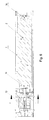
- Fig. 2 presents a damper in a cross-section along the line A-A of Fig. 1
- Fig. 3 presents a damper in a cross-section along the line E-E of Fig. 6
- Fig. 4 presents a lamella in a view from the side of the operating surface
- Fig. 5 presents a lamella in a cross-section according to the line C-C of Fig. 4
- fig. 6 presents a damper in a cross-section along the line B-B of Fig. 1
- Fig. 7 presents a damper in a cross-section along the line D-D of Fig.
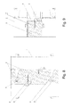
- Fig. 8 presents a section of a part of the damper in the close position showing the details of sealing between the lamellas
- Fig. 9 presents a cross-section of a part of the damper showing the lamellas at the side opposite to the actuator.
- the fire damper comprises a body 1 constituted by steel frame and lamellas 2 made of fire resistant material.
- the lamellas 2 are provided with gaskets and have two parallel operating surfaces 2a, two leading edges 2b and two side edges 2c.
- two rotational axes are fixed which are seated in two bearings arranged at the opposite vertical sides of the body 4, which is shown in Fig. 3 .
- the axes are fixed to the lamellas 2 by means of connectors 14 mounted to the lamellas with bolts 10.
- the lamellas 2 are connected to each other by means of strings 8 constituting the elements of actuating mechanism 13. The strings 8 make the lamellas 2 rotate which results in opening or closing of the fire damper.
- the reinforcing elements 12 are made of an angle section seated in a groove provided in the operating surface 2a of lamellas 2 along the length thereof.
- the angle section may be replaced by other profile, for example a T-bar, which is seated with its two arms in longitudinal, parallel grooves provided in a lamella 2 and fixed to it.
- the main task of the reinforcing element 12 is therefore reinforcement of a lamella 2 on a surface parallel to the operating surfaces 2a and extending through the center of a lamella 2.
- the reinforcing element 12 in this embodiment is made of carbon fiber but it may be made of any other durable material having resistance to high temperatures, for example fiber glass or steel.
- the reinforcing elements 12 and the connectors 14 are fixed to the lamellas 2 by means of adapter sleeves 11 fixed therein , and with bolts 10 screwed to the adapter sleeves 11, arranged in blind openings provided in lamellas 2 as shown in Fig. 2 , Fig. 5 , Fig. 8 and partially in Fig. 9 .
- Such an embodiment of this combination contributes to improving the leak tightness properties of the closed tire damper as it eliminates transmission of gases and smoke through bolt connections, in particular in the fire conditions at high differences in pressure, which may occur in the prior art where bolts pass through a passage made in a lamella 2, while providing the opportunity to replace a lamella 2 in case of failure in a way that does not require dismantling of the built-in damper.
- the driving mechanism 13 is connected with two strings 8 coupled with rotational levers 9 accommodated on the leading edges 2b of a lamella 2.
- the driving mechanism 13 and the strings 8 are accommodated in a separate thermally insulated chamber 7 within the body of the fire damper.
- strings 8 are made of carbon fiber but they may be made of any heat resistant material with regard to changes in length, such as fiber glass or steel.
- the strings 8 made in this embodiment of carbon fiber prevent the situation when as result of thermal expansion of strings 8 made of other material unsealing of the fire damper upon elongation of the strings 8 could occur.
- a sealing 3 made of silicone gaskets of an hollow O profile is mounted, having the task of ensuring the leak tightness between the lamellas 2, and between the lamellas 2 and the body 1 under normal operating conditions when not on fire and in the initial phase of fire protection against the leakage of gases and smoke when they are cold.
- the sealing 3 can be made of other materials resistant to high temperatures.
- intumescent gaskets are used, the first gasket 4, the second gasket 5 and the third gasket 6 having a task of ensuring the leak tightness between the lamellas 2, and between the lamellas and the body 1, during a fire.
- the intumescent gaskets 4, 5 and 6 differ in width (30, 40 and 60 mm respectively).
- the first gasket 4 is mounted at the longer side of each lamella 2 with staples.
- the second gasket 5 is adhered to the inner surface of the body 1 of the damper on the side of strings 10.
- the third gasket 6 is adhered to the inner surface of the body 1 of the damper at the other sides thereof.
- each lamella 2 two rotational axes have been fixed which are in turn fixed in two bearings arranged at opposite vertical sides of the body 1 of the damper.
- a possibility to dismantle is ensured by a specially designed axis of a lamella 2 which is slidingly inserted into the groove at short sides of a lamella 2 and fixed to the lamella 2 by means of a connector 14.
- the lamellas 2 have been connected to each other by means of strings 8 fixed to the lever 9, fixed on the rotational axis of a lamella 2, which was shown in Fig. 7 .
- the central lever 9 is connected by means of a shaft with an electric actuator constituting a driving mechanism 13 in this embodiment, accommodated in an insulation chamber 7.
- a driving mechanism 13 in this embodiment, accommodated in an insulation chamber 7.
- any other lever 9 can be connected with the driving mechanism 13.
- Movement (rotation) of any lamella 2 causes the same movement of other lamellas 2.
- a lamella 2 In case of fire damper shown in Fig. 1 , its opening can be performed automatically by means of a driving mechanism 13 by rotation of lamellas 2 by 90°. Upon opening, a lamella 2 is locked in an open position and then closed in case of need (fire alarm, periodical test of installation) by a driving mechanism 13 with an electric actuator as a result of transmitting a power signal to the actuator. In the transition of the damper from the open to the closed position the lamellas at no time exceed the outline of the body 1 of the damper.
- the damper according to the invention can be mounted:
- the mounting of the damper can take place in a vertical or horizontal position:
- the damper according to the invention is adapted for connection to:
- the damper is used in a ventilation or smoke installation as:
- the damper meets a fire resistance class EI 120 (v edw -h odw -i ⁇ o) S 1500Pa C 10000 AA multi or in case of using a thermal release EI 120 (ve-ho-i ⁇ o) S (500 Pa) and EI 120 in case of a transfer damper with a sheath grid.
- EI 120 v edw -h odw -i ⁇ o
Landscapes
- Health & Medical Sciences (AREA)
- Public Health (AREA)
- Business, Economics & Management (AREA)
- Emergency Management (AREA)
- Air-Flow Control Members (AREA)
- Building Environments (AREA)
Priority Applications (3)
| Application Number | Priority Date | Filing Date | Title |
|---|---|---|---|
| LTEP15460006.8T LT3061503T (lt) | 2015-02-27 | 2015-02-27 | Priešgaisrinė sklendė |
| PL15460006T PL3061503T3 (pl) | 2015-02-27 | 2015-02-27 | Klapa odcinająca |
| EP15460006.8A EP3061503B1 (fr) | 2015-02-27 | 2015-02-27 | Clapet coupe-feu |
Applications Claiming Priority (1)
| Application Number | Priority Date | Filing Date | Title |
|---|---|---|---|
| EP15460006.8A EP3061503B1 (fr) | 2015-02-27 | 2015-02-27 | Clapet coupe-feu |
Publications (2)
| Publication Number | Publication Date |
|---|---|
| EP3061503A1 true EP3061503A1 (fr) | 2016-08-31 |
| EP3061503B1 EP3061503B1 (fr) | 2018-10-03 |
Family
ID=53015753
Family Applications (1)
| Application Number | Title | Priority Date | Filing Date |
|---|---|---|---|
| EP15460006.8A Active EP3061503B1 (fr) | 2015-02-27 | 2015-02-27 | Clapet coupe-feu |
Country Status (3)
| Country | Link |
|---|---|
| EP (1) | EP3061503B1 (fr) |
| LT (1) | LT3061503T (fr) |
| PL (1) | PL3061503T3 (fr) |
Cited By (4)
| Publication number | Priority date | Publication date | Assignee | Title |
|---|---|---|---|---|
| DE102017005252A1 (de) * | 2017-06-01 | 2018-12-06 | Gert Bartholomäus | Kaltrauchsperre mit leichtgewichtigem Verschlussblatt |
| EP3603750A1 (fr) | 2018-07-31 | 2020-02-05 | Grempco S.A. | Volet de désenfumage et son étanchéité |
| CN117783417A (zh) * | 2024-02-27 | 2024-03-29 | 达州增美玄武岩纤维科技有限公司 | 一种玄武岩纤维复合材料防火布移动测试平台及测试方法 |
| DE202023100853U1 (de) * | 2023-02-23 | 2024-06-17 | Wildeboer Bauteile Gmbh | Brandschutz- und Entrauchungseinrichtung |
Citations (4)
| Publication number | Priority date | Publication date | Assignee | Title |
|---|---|---|---|---|
| EP0583156A1 (fr) * | 1992-08-12 | 1994-02-16 | Kvaerner Masa-Yards Oy | Elément de fermeture de feu |
| US6019679A (en) | 1998-11-09 | 2000-02-01 | Lloyd Industries | Fire and smoke damper |
| GB2388616A (en) * | 2002-05-15 | 2003-11-19 | Natabelle Technology Ltd | Pressure relief wall panel |
| EP2366435A1 (fr) | 2010-03-15 | 2011-09-21 | Grempco S.A. | Clapet coupe-feu |
-
2015
- 2015-02-27 LT LTEP15460006.8T patent/LT3061503T/lt unknown
- 2015-02-27 EP EP15460006.8A patent/EP3061503B1/fr active Active
- 2015-02-27 PL PL15460006T patent/PL3061503T3/pl unknown
Patent Citations (4)
| Publication number | Priority date | Publication date | Assignee | Title |
|---|---|---|---|---|
| EP0583156A1 (fr) * | 1992-08-12 | 1994-02-16 | Kvaerner Masa-Yards Oy | Elément de fermeture de feu |
| US6019679A (en) | 1998-11-09 | 2000-02-01 | Lloyd Industries | Fire and smoke damper |
| GB2388616A (en) * | 2002-05-15 | 2003-11-19 | Natabelle Technology Ltd | Pressure relief wall panel |
| EP2366435A1 (fr) | 2010-03-15 | 2011-09-21 | Grempco S.A. | Clapet coupe-feu |
Cited By (6)
| Publication number | Priority date | Publication date | Assignee | Title |
|---|---|---|---|---|
| DE102017005252A1 (de) * | 2017-06-01 | 2018-12-06 | Gert Bartholomäus | Kaltrauchsperre mit leichtgewichtigem Verschlussblatt |
| DE102017005252B4 (de) | 2017-06-01 | 2020-07-30 | Gert Bartholomäus | Kaltrauchsperre mit leichtgewichtigem Verschlussblatt |
| EP3603750A1 (fr) | 2018-07-31 | 2020-02-05 | Grempco S.A. | Volet de désenfumage et son étanchéité |
| DE202023100853U1 (de) * | 2023-02-23 | 2024-06-17 | Wildeboer Bauteile Gmbh | Brandschutz- und Entrauchungseinrichtung |
| CN117783417A (zh) * | 2024-02-27 | 2024-03-29 | 达州增美玄武岩纤维科技有限公司 | 一种玄武岩纤维复合材料防火布移动测试平台及测试方法 |
| CN117783417B (zh) * | 2024-02-27 | 2024-05-07 | 达州增美玄武岩纤维科技有限公司 | 一种玄武岩纤维复合材料防火布移动测试平台及测试方法 |
Also Published As
| Publication number | Publication date |
|---|---|
| EP3061503B1 (fr) | 2018-10-03 |
| LT3061503T (lt) | 2019-01-25 |
| PL3061503T3 (pl) | 2019-05-31 |
Similar Documents
| Publication | Publication Date | Title |
|---|---|---|
| EP3061503B1 (fr) | Clapet coupe-feu | |
| EP3542870B1 (fr) | Système de ventilation d'un bâtiment doté d'une fonctionnalité d'évacuation de fumée et procédé de fonctionnement dudit système | |
| RU2008143561A (ru) | Противопожарный барьер для фюзеляжа самолета | |
| US20200408428A1 (en) | Multi-component whole house fan system | |
| EP2366435B1 (fr) | Clapet coupe-feu | |
| US6019679A (en) | Fire and smoke damper | |
| CN108644435B (zh) | 楼梯间远程可控泄压装置及泄压系统 | |
| EP2741022B1 (fr) | Amortisseur d'évacuation de fumée comprenant une pièce de matériau intumescent | |
| EP2537562B1 (fr) | Obturateur d'évacuation de fumée | |
| EP2239014A1 (fr) | Clapet coupe-feu | |
| CN110057017B (zh) | 一种防火排烟系统及其控制方法 | |
| CN208220452U (zh) | 一种磁性自动锁定机构以及安装该机构的耐火窗、防火窗 | |
| US20120193073A1 (en) | Device for building ventilation | |
| CN215172571U (zh) | 一种具有监测功能的防火、排烟阀 | |
| EP4596988A1 (fr) | Amortisseur d'échappement de fumée | |
| EP2229984B1 (fr) | Clapet coupe-feu avec une section rectangulaire et un système d'étanchéité | |
| EP4643959A1 (fr) | Clapet coupe-feu ou d'évacuation de fumée | |
| EP3469268A1 (fr) | Procédés et moyens pour systèmes de ventilation à bon rendement énergétique pour bâtiments | |
| WO2014173584A1 (fr) | Améliorations concernant des clapets coupe-feu | |
| CN209724125U (zh) | 一种消防通道用防火门设备 | |
| KR100728799B1 (ko) | 수평식 제연 경계벽 작동 장치 | |
| WO2021215924A1 (fr) | Description de fusible à fusion | |
| JP7733977B2 (ja) | 換気装置、内窓、二重窓 | |
| KR20250001549U (ko) | 방화댐퍼 | |
| KR102939717B1 (ko) | 에어덕트용 방화댐퍼 |
Legal Events
| Date | Code | Title | Description |
|---|---|---|---|
| PUAI | Public reference made under article 153(3) epc to a published international application that has entered the european phase |
Free format text: ORIGINAL CODE: 0009012 |
|
| 17P | Request for examination filed |
Effective date: 20150311 |
|
| AK | Designated contracting states |
Kind code of ref document: A1 Designated state(s): AL AT BE BG CH CY CZ DE DK EE ES FI FR GB GR HR HU IE IS IT LI LT LU LV MC MK MT NL NO PL PT RO RS SE SI SK SM TR |
|
| AX | Request for extension of the european patent |
Extension state: BA ME |
|
| STAA | Information on the status of an ep patent application or granted ep patent |
Free format text: STATUS: REQUEST FOR EXAMINATION WAS MADE |
|
| GRAP | Despatch of communication of intention to grant a patent |
Free format text: ORIGINAL CODE: EPIDOSNIGR1 |
|
| STAA | Information on the status of an ep patent application or granted ep patent |
Free format text: STATUS: GRANT OF PATENT IS INTENDED |
|
| RIC1 | Information provided on ipc code assigned before grant |
Ipc: A62C 2/14 20060101AFI20170925BHEP Ipc: F24F 13/15 20060101ALI20170925BHEP Ipc: F24F 11/00 20060101ALI20170925BHEP |
|
| INTG | Intention to grant announced |
Effective date: 20171027 |
|
| GRAJ | Information related to disapproval of communication of intention to grant by the applicant or resumption of examination proceedings by the epo deleted |
Free format text: ORIGINAL CODE: EPIDOSDIGR1 |
|
| STAA | Information on the status of an ep patent application or granted ep patent |
Free format text: STATUS: REQUEST FOR EXAMINATION WAS MADE |
|
| GRAP | Despatch of communication of intention to grant a patent |
Free format text: ORIGINAL CODE: EPIDOSNIGR1 |
|
| STAA | Information on the status of an ep patent application or granted ep patent |
Free format text: STATUS: GRANT OF PATENT IS INTENDED |
|
| GRAS | Grant fee paid |
Free format text: ORIGINAL CODE: EPIDOSNIGR3 |
|
| INTC | Intention to grant announced (deleted) | ||
| INTG | Intention to grant announced |
Effective date: 20180205 |
|
| GRAA | (expected) grant |
Free format text: ORIGINAL CODE: 0009210 |
|
| STAA | Information on the status of an ep patent application or granted ep patent |
Free format text: STATUS: THE PATENT HAS BEEN GRANTED |
|
| AK | Designated contracting states |
Kind code of ref document: B1 Designated state(s): AL AT BE BG CH CY CZ DE DK EE ES FI FR GB GR HR HU IE IS IT LI LT LU LV MC MK MT NL NO PL PT RO RS SE SI SK SM TR |
|
| REG | Reference to a national code |
Ref country code: GB Ref legal event code: FG4D |
|
| REG | Reference to a national code |
Ref country code: CH Ref legal event code: EP Ref country code: AT Ref legal event code: REF Ref document number: 1047989 Country of ref document: AT Kind code of ref document: T Effective date: 20181015 |
|
| REG | Reference to a national code |
Ref country code: IE Ref legal event code: FG4D Ref country code: DE Ref legal event code: R096 Ref document number: 602015017443 Country of ref document: DE |
|
| REG | Reference to a national code |
Ref country code: CH Ref legal event code: NV Representative=s name: FELBER UND PARTNER AG, CH |
|
| REG | Reference to a national code |
Ref country code: RO Ref legal event code: EPE |
|
| REG | Reference to a national code |
Ref country code: NL Ref legal event code: FP |
|
| REG | Reference to a national code |
Ref country code: SE Ref legal event code: TRGR |
|
| REG | Reference to a national code |
Ref country code: NO Ref legal event code: T2 Effective date: 20181003 |
|
| REG | Reference to a national code |
Ref country code: EE Ref legal event code: FG4A Ref document number: E016759 Country of ref document: EE Effective date: 20190103 |
|
| PG25 | Lapsed in a contracting state [announced via postgrant information from national office to epo] |
Ref country code: BG Free format text: LAPSE BECAUSE OF FAILURE TO SUBMIT A TRANSLATION OF THE DESCRIPTION OR TO PAY THE FEE WITHIN THE PRESCRIBED TIME-LIMIT Effective date: 20190103 Ref country code: HR Free format text: LAPSE BECAUSE OF FAILURE TO SUBMIT A TRANSLATION OF THE DESCRIPTION OR TO PAY THE FEE WITHIN THE PRESCRIBED TIME-LIMIT Effective date: 20181003 Ref country code: IS Free format text: LAPSE BECAUSE OF FAILURE TO SUBMIT A TRANSLATION OF THE DESCRIPTION OR TO PAY THE FEE WITHIN THE PRESCRIBED TIME-LIMIT Effective date: 20190203 Ref country code: ES Free format text: LAPSE BECAUSE OF FAILURE TO SUBMIT A TRANSLATION OF THE DESCRIPTION OR TO PAY THE FEE WITHIN THE PRESCRIBED TIME-LIMIT Effective date: 20181003 Ref country code: LV Free format text: LAPSE BECAUSE OF FAILURE TO SUBMIT A TRANSLATION OF THE DESCRIPTION OR TO PAY THE FEE WITHIN THE PRESCRIBED TIME-LIMIT Effective date: 20181003 |
|
| PG25 | Lapsed in a contracting state [announced via postgrant information from national office to epo] |
Ref country code: AL Free format text: LAPSE BECAUSE OF FAILURE TO SUBMIT A TRANSLATION OF THE DESCRIPTION OR TO PAY THE FEE WITHIN THE PRESCRIBED TIME-LIMIT Effective date: 20181003 Ref country code: RS Free format text: LAPSE BECAUSE OF FAILURE TO SUBMIT A TRANSLATION OF THE DESCRIPTION OR TO PAY THE FEE WITHIN THE PRESCRIBED TIME-LIMIT Effective date: 20181003 Ref country code: GR Free format text: LAPSE BECAUSE OF FAILURE TO SUBMIT A TRANSLATION OF THE DESCRIPTION OR TO PAY THE FEE WITHIN THE PRESCRIBED TIME-LIMIT Effective date: 20190104 Ref country code: PT Free format text: LAPSE BECAUSE OF FAILURE TO SUBMIT A TRANSLATION OF THE DESCRIPTION OR TO PAY THE FEE WITHIN THE PRESCRIBED TIME-LIMIT Effective date: 20190203 |
|
| REG | Reference to a national code |
Ref country code: DE Ref legal event code: R097 Ref document number: 602015017443 Country of ref document: DE |
|
| PG25 | Lapsed in a contracting state [announced via postgrant information from national office to epo] |
Ref country code: IT Free format text: LAPSE BECAUSE OF FAILURE TO SUBMIT A TRANSLATION OF THE DESCRIPTION OR TO PAY THE FEE WITHIN THE PRESCRIBED TIME-LIMIT Effective date: 20181003 Ref country code: DK Free format text: LAPSE BECAUSE OF FAILURE TO SUBMIT A TRANSLATION OF THE DESCRIPTION OR TO PAY THE FEE WITHIN THE PRESCRIBED TIME-LIMIT Effective date: 20181003 |
|
| PLBE | No opposition filed within time limit |
Free format text: ORIGINAL CODE: 0009261 |
|
| STAA | Information on the status of an ep patent application or granted ep patent |
Free format text: STATUS: NO OPPOSITION FILED WITHIN TIME LIMIT |
|
| PG25 | Lapsed in a contracting state [announced via postgrant information from national office to epo] |
Ref country code: SK Free format text: LAPSE BECAUSE OF FAILURE TO SUBMIT A TRANSLATION OF THE DESCRIPTION OR TO PAY THE FEE WITHIN THE PRESCRIBED TIME-LIMIT Effective date: 20181003 Ref country code: SM Free format text: LAPSE BECAUSE OF FAILURE TO SUBMIT A TRANSLATION OF THE DESCRIPTION OR TO PAY THE FEE WITHIN THE PRESCRIBED TIME-LIMIT Effective date: 20181003 |
|
| 26N | No opposition filed |
Effective date: 20190704 |
|
| GBPC | Gb: european patent ceased through non-payment of renewal fee |
Effective date: 20190227 |
|
| PG25 | Lapsed in a contracting state [announced via postgrant information from national office to epo] |
Ref country code: SI Free format text: LAPSE BECAUSE OF FAILURE TO SUBMIT A TRANSLATION OF THE DESCRIPTION OR TO PAY THE FEE WITHIN THE PRESCRIBED TIME-LIMIT Effective date: 20181003 Ref country code: LU Free format text: LAPSE BECAUSE OF NON-PAYMENT OF DUE FEES Effective date: 20190227 Ref country code: MC Free format text: LAPSE BECAUSE OF FAILURE TO SUBMIT A TRANSLATION OF THE DESCRIPTION OR TO PAY THE FEE WITHIN THE PRESCRIBED TIME-LIMIT Effective date: 20181003 |
|
| REG | Reference to a national code |
Ref country code: IE Ref legal event code: MM4A |
|
| PG25 | Lapsed in a contracting state [announced via postgrant information from national office to epo] |
Ref country code: GB Free format text: LAPSE BECAUSE OF NON-PAYMENT OF DUE FEES Effective date: 20190227 Ref country code: IE Free format text: LAPSE BECAUSE OF NON-PAYMENT OF DUE FEES Effective date: 20190227 |
|
| PG25 | Lapsed in a contracting state [announced via postgrant information from national office to epo] |
Ref country code: TR Free format text: LAPSE BECAUSE OF FAILURE TO SUBMIT A TRANSLATION OF THE DESCRIPTION OR TO PAY THE FEE WITHIN THE PRESCRIBED TIME-LIMIT Effective date: 20181003 |
|
| PG25 | Lapsed in a contracting state [announced via postgrant information from national office to epo] |
Ref country code: MT Free format text: LAPSE BECAUSE OF NON-PAYMENT OF DUE FEES Effective date: 20190227 |
|
| REG | Reference to a national code |
Ref country code: AT Ref legal event code: UEP Ref document number: 1047989 Country of ref document: AT Kind code of ref document: T Effective date: 20181003 |
|
| PG25 | Lapsed in a contracting state [announced via postgrant information from national office to epo] |
Ref country code: CY Free format text: LAPSE BECAUSE OF FAILURE TO SUBMIT A TRANSLATION OF THE DESCRIPTION OR TO PAY THE FEE WITHIN THE PRESCRIBED TIME-LIMIT Effective date: 20181003 |
|
| PG25 | Lapsed in a contracting state [announced via postgrant information from national office to epo] |
Ref country code: HU Free format text: LAPSE BECAUSE OF FAILURE TO SUBMIT A TRANSLATION OF THE DESCRIPTION OR TO PAY THE FEE WITHIN THE PRESCRIBED TIME-LIMIT; INVALID AB INITIO Effective date: 20150227 |
|
| PG25 | Lapsed in a contracting state [announced via postgrant information from national office to epo] |
Ref country code: MK Free format text: LAPSE BECAUSE OF FAILURE TO SUBMIT A TRANSLATION OF THE DESCRIPTION OR TO PAY THE FEE WITHIN THE PRESCRIBED TIME-LIMIT Effective date: 20181003 |
|
| PGFP | Annual fee paid to national office [announced via postgrant information from national office to epo] |
Ref country code: LT Payment date: 20240227 Year of fee payment: 10 |
|
| PGFP | Annual fee paid to national office [announced via postgrant information from national office to epo] |
Ref country code: RO Payment date: 20240227 Year of fee payment: 10 Ref country code: CZ Payment date: 20240227 Year of fee payment: 10 |
|
| PGFP | Annual fee paid to national office [announced via postgrant information from national office to epo] |
Ref country code: NL Payment date: 20250228 Year of fee payment: 11 |
|
| PGFP | Annual fee paid to national office [announced via postgrant information from national office to epo] |
Ref country code: SE Payment date: 20250228 Year of fee payment: 11 |
|
| PGFP | Annual fee paid to national office [announced via postgrant information from national office to epo] |
Ref country code: FI Payment date: 20250228 Year of fee payment: 11 |
|
| PGFP | Annual fee paid to national office [announced via postgrant information from national office to epo] |
Ref country code: NO Payment date: 20250303 Year of fee payment: 11 |
|
| PGFP | Annual fee paid to national office [announced via postgrant information from national office to epo] |
Ref country code: CH Payment date: 20250301 Year of fee payment: 11 Ref country code: BE Payment date: 20250228 Year of fee payment: 11 Ref country code: AT Payment date: 20250228 Year of fee payment: 11 Ref country code: EE Payment date: 20250303 Year of fee payment: 11 |
|
| PGFP | Annual fee paid to national office [announced via postgrant information from national office to epo] |
Ref country code: PL Payment date: 20250227 Year of fee payment: 11 |
|
| REG | Reference to a national code |
Ref country code: LT Ref legal event code: MM4D Effective date: 20250227 |
|
| PG25 | Lapsed in a contracting state [announced via postgrant information from national office to epo] |
Ref country code: LT Free format text: LAPSE BECAUSE OF NON-PAYMENT OF DUE FEES Effective date: 20250227 |
|
| PGFP | Annual fee paid to national office [announced via postgrant information from national office to epo] |
Ref country code: DE Payment date: 20250702 Year of fee payment: 11 |
|
| PGFP | Annual fee paid to national office [announced via postgrant information from national office to epo] |
Ref country code: FR Payment date: 20250703 Year of fee payment: 11 |
|
| PG25 | Lapsed in a contracting state [announced via postgrant information from national office to epo] |
Ref country code: CZ Free format text: LAPSE BECAUSE OF NON-PAYMENT OF DUE FEES Effective date: 20250227 |
|
| PG25 | Lapsed in a contracting state [announced via postgrant information from national office to epo] |
Ref country code: RO Free format text: LAPSE BECAUSE OF NON-PAYMENT OF DUE FEES Effective date: 20250227 |