EP3061923B1 - Procédés et systèmes de distribution de détergent pour moteurs à turbine - Google Patents
Procédés et systèmes de distribution de détergent pour moteurs à turbine Download PDFInfo
- Publication number
- EP3061923B1 EP3061923B1 EP16154844.1A EP16154844A EP3061923B1 EP 3061923 B1 EP3061923 B1 EP 3061923B1 EP 16154844 A EP16154844 A EP 16154844A EP 3061923 B1 EP3061923 B1 EP 3061923B1
- Authority
- EP
- European Patent Office
- Prior art keywords
- detergent
- baffle plate
- baffle
- back side
- turbine engine
- Prior art date
- Legal status (The legal status is an assumption and is not a legal conclusion. Google has not performed a legal analysis and makes no representation as to the accuracy of the status listed.)
- Active
Links
Images


Classifications
-
- B—PERFORMING OPERATIONS; TRANSPORTING
- B64—AIRCRAFT; AVIATION; COSMONAUTICS
- B64F—GROUND OR AIRCRAFT-CARRIER-DECK INSTALLATIONS SPECIALLY ADAPTED FOR USE IN CONNECTION WITH AIRCRAFT; DESIGNING, MANUFACTURING, ASSEMBLING, CLEANING, MAINTAINING OR REPAIRING AIRCRAFT, NOT OTHERWISE PROVIDED FOR; HANDLING, TRANSPORTING, TESTING OR INSPECTING AIRCRAFT COMPONENTS, NOT OTHERWISE PROVIDED FOR
- B64F5/00—Designing, manufacturing, assembling, cleaning, maintaining or repairing aircraft, not otherwise provided for; Handling, transporting, testing or inspecting aircraft components, not otherwise provided for
- B64F5/30—Cleaning aircraft
-
- F—MECHANICAL ENGINEERING; LIGHTING; HEATING; WEAPONS; BLASTING
- F01—MACHINES OR ENGINES IN GENERAL; ENGINE PLANTS IN GENERAL; STEAM ENGINES
- F01D—NON-POSITIVE DISPLACEMENT MACHINES OR ENGINES, e.g. STEAM TURBINES
- F01D25/00—Component parts, details, or accessories, not provided for in, or of interest apart from, other groups
- F01D25/002—Cleaning of turbomachines
-
- B—PERFORMING OPERATIONS; TRANSPORTING
- B08—CLEANING
- B08B—CLEANING IN GENERAL; PREVENTION OF FOULING IN GENERAL
- B08B9/00—Cleaning hollow articles by methods or apparatus specially adapted thereto
- B08B9/02—Cleaning pipes or tubes or systems of pipes or tubes
- B08B9/027—Cleaning the internal surfaces; Removal of blockages
- B08B9/032—Cleaning the internal surfaces; Removal of blockages by the mechanical action of a moving fluid, e.g. by flushing
-
- F—MECHANICAL ENGINEERING; LIGHTING; HEATING; WEAPONS; BLASTING
- F01—MACHINES OR ENGINES IN GENERAL; ENGINE PLANTS IN GENERAL; STEAM ENGINES
- F01D—NON-POSITIVE DISPLACEMENT MACHINES OR ENGINES, e.g. STEAM TURBINES
- F01D25/00—Component parts, details, or accessories, not provided for in, or of interest apart from, other groups
- F01D25/08—Cooling; Heating; Heat-insulation
- F01D25/12—Cooling
-
- F—MECHANICAL ENGINEERING; LIGHTING; HEATING; WEAPONS; BLASTING
- F05—INDEXING SCHEMES RELATING TO ENGINES OR PUMPS IN VARIOUS SUBCLASSES OF CLASSES F01-F04
- F05D—INDEXING SCHEME FOR ASPECTS RELATING TO NON-POSITIVE-DISPLACEMENT MACHINES OR ENGINES, GAS-TURBINES OR JET-PROPULSION PLANTS
- F05D2220/00—Application
- F05D2220/30—Application in turbines
- F05D2220/32—Application in turbines in gas turbines
- F05D2220/323—Application in turbines in gas turbines for aircraft propulsion, e.g. jet engines
-
- F—MECHANICAL ENGINEERING; LIGHTING; HEATING; WEAPONS; BLASTING
- F05—INDEXING SCHEMES RELATING TO ENGINES OR PUMPS IN VARIOUS SUBCLASSES OF CLASSES F01-F04
- F05D—INDEXING SCHEME FOR ASPECTS RELATING TO NON-POSITIVE-DISPLACEMENT MACHINES OR ENGINES, GAS-TURBINES OR JET-PROPULSION PLANTS
- F05D2260/00—Function
- F05D2260/20—Heat transfer, e.g. cooling
- F05D2260/221—Improvement of heat transfer
Definitions
- the present application relates generally to methods and system for internal cleaning of turbine engines, and more particularly to methods and system of cleaning internal cooling circuits of turbine engines with detergent.
- Turbines such as gas turbine engines, typically include internal cooling passages that are designed to impingement cool one or more components during use.
- the high pressure section of a gas turbine engine typically includes numerous circumferentially-arranged impingement internal cooling circuits that allow for higher temperatures in the turbine.
- impingement internal cooling circuits of turbine engines tend to become partially or completely blocked with particulate matter that reduces the cooling efficiency of the circuits.
- particulate matter may enter a turbine engine during service or during use, such as during environmental events such as dust storms.
- the particulate matter may be fine scale (e.g., less than 10 microns) dust, debris or other pollutants (reacted or non-reacted).
- the particulate matter may also become deposited on cooled components and create an insulating layer between the surface of the component and the cooling medium of the cooling circuits.
- the reduced cooling efficiency created by the at least partially blocked cooling circuits and the insulating layers on the cooled components can increase the operating temperature and reduce the life of the components.
- the particulate matter that is entrained in the air that enters the turbine engine and travels within the cooling circuits can contain sulphur-containing species which can corrode components of the turbine.
- turbine engines may be removed from service (e.g., detached from the aircraft, power plant or other machine that the engine powers or is otherwise used with) and substantially dismantled to provide direct access to the internal cooling passages for cleaning.
- service e.g., detached from the aircraft, power plant or other machine that the engine powers or is otherwise used with
- substantially dismantled to provide direct access to the internal cooling passages for cleaning.
- the circumferentially arranged cooling circuits are cleaned individually and not in situ.
- US 2009/0084411 is concerned with on-wing combustor cleaning using direct insertion nozzle, wash agent, and procedure.
- US 2014/0190347 is concerned with liquid injection inlet particle separator systems and methods.
- the present disclosure provides a method of cleaning a turbine engine that includes at least one internal impingement cooling circuit with a baffle plate configured to air cool a component of the turbine engine.
- the method includes introducing detergent to a back side of a baffle plate of the turbine engine such that the detergent passes through at least one aperture in the baffle plate and acts at least upon the component that the baffle plate is configured to air impingement cool to clean matter from the component.
- Introducing detergent to a back side of a baffle plate of the turbine engine may comprise introducing detergent into a pre-baffle cavity positioned proximate to the back side of the baffle plate.
- the method may further include accessing the back side of the baffle plate of the turbine engine through a port in an outer wall of the turbine engine.
- the port in the outer wall of the turbine engine may provide a passageway to an internal cooling air channel of a respective internal impingement cooling circuit that feeds the baffle plate with air to air cool the component.
- the port may be an aperture in an outer case of the turbine engine configured to house a fuel line coupled to a fuel nozzle.
- Accessing a back side of a baffle plate of the turbine engine through a port in an outer wall of the turbine engine may include positioning a detergent delivery mechanism through the port and proximate to the back side of the baffle plate.
- the impingement-cooled component may be a shroud coupled to a shroud hanger positioned at least partially on the back side of the shroud.
- the detergent may be passed through at least one aperture in the hanger and may be introduced into a pre-baffle cavity between the hanger and the back side of the shroud.
- the detergent may act on a front side of the baffle plate that substantially faces the component that the baffle plate is configured to air impingement cool.
- the detergent may include an acidic, water-based reagent including an organic surfactant and a corrosion inhibitor designed to selectively dissolve at least one of sulfate, chloride and carbonate based species while being substantially unreactive with the material forming the component.
- the turbine engine may be attached to an aircraft.
- the internal impingement cooling circuits may include a plurality of circumferentially arranged cooling circuits each including a baffle plate configured to cool a respective one of circumferentially arranged components.
- the method may include substantially simultaneously introducing detergent to the back side of a plurality of the circumferentially arranged baffle plates such that the detergent passes through apertures in the baffle plates and acts at least upon the respective circumferentially arranged components that the baffle plates are configured to air cool.
- the cleaning method may include introducing detergent to a back side of a baffle plate of the turbine engine such that the detergent passes through a plurality of apertures in the baffle plate to form a plurality of discrete jets of detergent that act at least upon the component that the baffle plate is configured to air impingement cool to clean matter from the component.
- the present disclosure provides a method of cleaning a turbine engine.
- the method includes obtaining a turbine engine including circumferentially arranged internal impingement cooling circuits each with a baffle plate configured to air impingement cool a respective circumferentially arranged component of the turbine engine, wherein the baffle plates each include a back side, a front side positioned proximate to the respective component, and at least one aperture extending from the front side to the back side.
- the method further includes positioning a detergent delivery mechanism through at least one access aperture in the outer wall of the turbine and proximate to the back side of the baffle plates.
- the method also includes introducing detergent to the back side of the baffle plates via the detergent delivery mechanism such that the detergent passes through the at least one aperture in the baffle plates and acts upon the components and the front sides of the baffle plates to clean matter therefrom.
- the components may be circumferentially arranged shrouds each coupled to a shroud hanger positioned at least partially on the back side of the shrouds, and the method may include passing the detergent through an aperture in each of the hangers and into a pre-baffle cavity formed between the hangers and the back sides of the baffle plates.
- the aperture in each of the hangers may be in communication with the respective internal cooling passageway of the respective circumferentially arranged internal impingement cooling circuit to feed air to the respective baffle plate to air cool the respective component.
- the turbine engine may be attached to an aircraft.
- the detergent may include an acidic, water-based reagent including an organic surfactant and a corrosion inhibitor designed to selectively dissolve at least one of sulfate, chloride and carbonate based species while being substantially unreactive with the material forming the components.
- the present disclosure provides a system for cleaning a turbine engine that includes at least one internal impingement cooling circuit with an internal cooling passageway in communication with a baffle plate that is configured to air cool a component of the turbine engine.
- the system includes a detergent delivery mechanism extending through an opening in the outer wall of the turbine and proximate to a back side of the baffle plate.
- the system further includes a source of detergent including an acidic, water-based reagent with an organic surfactant and a corrosion inhibitor in fluid communication with the detergent delivery mechanism.
- the component may be a shroud coupled to a shroud hanger positioned at least partially on the back side of the shroud, and the detergent delivery mechanism may extend to an aperture in the shroud hanger to deliver the detergent into a pre-baffle cavity that is formed between the shroud hanger and the back side of the baffle plate.
- the detergent delivery mechanism may extend to a pre-baffle cavity that is proximate to a back side of the baffle plate.
- the source of a detergent including an acidic, water-based reagent may be configured to deliver the detergent to the back side of the baffle via the detergent delivery mechanism such that the delivered detergent passes through apertures in the baffle plate and acts upon the component and a front side of the baffle plate to clean matter from therefrom.
- Methods and systems according to the present disclosure provide for in situ uniform circumferential cleaning of the internal impingement cooling circuits of a turbine engine (i.e., cleaning around the full circumference of the turbine), without substantial disassembly of the engine, with detergent to remove matter therefrom to restore or improve the cooling efficiency of the circuits, and thereby the performance of the turbine.
- the methods and systems of cleaning internal impingement cooling circuits of a turbine engine according to the present disclosure may be effective in returning the cooling features of the components that the internal impingement cooling circuits are configured to impingement cool to their original condition before entry into service.
- the cleaning methods and systems according to the present disclosure may also provide for removal of matter from the components of the internal impingement cooling circuit and/or the components or surfaces that the internal impingement cooling circuits are configured to impingement cool that includes the most (or the most difficult to remove) matter deposited thereon so that the performance, lifespan or function of the component is substantially corrected or fully restored.
- the methods and systems according to the present disclosure may provide for cleaning the "dirtiest" impingement cooling circuit (such as the circuit including the "dirtiest" impingement cooled component) of the circumferentially arranged impingement cooling circuits to ensure that the entirety of the circumferentially arranged impingement cooling circuits are corrected or restored.
- the methods and systems according to the present disclosure may provide for effective cleaning of the region of each circuit and/or cooled component that is the "dirtiest" so that the performance, life span and/or function of even the worst area of the circuit and/or cooled component is substantially corrected or restored to an acceptable level for effective impingement cooling during use of the turbine.
- the methods and systems of cleaning turbine internal impingement cooling circuits according to the present disclosure may be configured to clean internal cooling passages of a gas turbine engine with detergent by delivering the detergent through one or more access, ports or aperture in the outer wall of the turbine without substantial disassembly of the turbine engine.
- the turbine internal impingement cooling circuit cleaning methods and systems may be configured to deliver cleaning detergent in passages of the impingement cooling circuits that typically operate at air pressures of up to 69 Bar (1,000 psi) during normal or typical turbine engine service.
- the methods and systems of cleaning turbine internal impingement cooling circuits according to the present disclosure may utilize the baffle plate system of internal impingement cooling circuits (i.e., baffle plates that are used in for impingement cooling) to deliver detergent to components that the baffle plates are configured to cool to improve cleaning efficiency of the components.
- baffle plate system of internal impingement cooling circuits i.e., baffle plates that are used in for impingement cooling
- an internal impingement cooling circuit of a turbine engine that is utilized to clean a turbine engine may be any turbine cooling circuit that includes a pre-impingement baffle cavity or plenum, a baffle or baffle plate with at least one aperture therethrough, and a post-baffle cavity that, collectively, are configured to impingement cool a component, surface or portion of the turbine engine, typically during operation of the turbine engine.
- the pre-baffle cavity is arranged or positioned upstream of the impingement baffle plate and is configured to feed cooling air or other material through the at least one aperture in the baffle plate
- the post-baffle cavity is arranged or positioned downstream of the baffle and proximate or adjacent to the impingement cooled component or surface.
- baffle or baffle plate is used herein to refer to any component, portion, surface or mechanism that includes at least one aperture extending therethrough that acts to generate at least one discrete cooling jet that impinges on a surface or component in the post-baffle cavity of an internal impingement cooling circuit of a turbine engine to cool the surface or component.
- baffle plate discussed below with respect to FIGS.
- baffle plate 1-9 (with an impingement cooled shroud) is only one exemplary baffle plate embodiment, and any other component, portion, surface or mechanism that includes at least one aperture extending therethrough that acts to generate at least one discrete cooling jet that impinges on a surface or component in a post-baffle cavity of an internal impingement cooling circuit of a turbine engine maybe utilized in the cleaning methods and systems disclosed herein.
- pre-baffle and post-baffle cavities there are a wide range of geometries and configurations of substantially enclosed volumes that serve as pre-baffle and post-baffle cavities, as well as components, portions, surfaces or mechanisms that act as a baffle plate, of differing internal impingement cooling circuit in turbines.
- Any arrangement of a pre-baffle cavity, at least one aperture that generates a discrete cooling jet (referred to in general herein as a baffle plate), and a component or surface that is impingement cooled by the at least one discrete jet in the post-baffle cavity may be utilized by the methods and systems described herein to clean a turbine.
- detergent is introduced into or otherwise enters a pre-baffle cavity or plenum of at least one internal impingement cooling circuit, and passes through the at least one aperture in the baffle to clean material from a component or surface of the turbine, such as the component or surface that the at least one internal impingement cooling circuit typically or otherwise impingent cools.
- the methods and systems of cleaning internal impingement cooling circuits of the present disclosure are configured to employ a pre-existing impingement cooling configuration to establish suitable detergent flow conditions that effectively and efficiently clean foreign material from the full area of the impingement cooled surface or component.
- effective and efficient cleaning according to the present disclosure is performed by "spraying" detergent through a pre-existing baffle plate that is used in a turbine engine for impingement cooling to clean the impingement-cooled internal component or surface of the turbine.
- the inventors have determined that the detergent jets can be configured such that each cleaned surface or component of the internal impingement cooling circuits is cleaned uniformly over the full area of the impingement cooled surface or component.
- each of the cooling circuits around the full circumference of the engine can be cleaned uniformly (i.e., each impingement cooling circuit provides at least a minimum cleaning efficiency that is effective in removing foreign material from the full area of the impingement cooled surface or component).
- a number of factors that affect the efficiency and effectiveness of the methods and systems of the present disclosure to clean foreign matter from the cooled components or surfaces of a turbine engine have been recognized.
- the inventors have determined that the delivery pressure of the detergent in the pre-baffle cavity, the flow rate of the detergent through the aperture(s) of the baffle plate, the number of apertures in the baffle plate, the velocity of the detergent when it exits the baffle plate, the velocity of the detergent when it impacts the matter on the cooled component or surface, and the shear stress generated in the matter by the detergent each affect the efficiency and effectiveness of utilizing detergent and impingement cooling circuits to clean foreign matter from the cooled components or surfaces.
- the pattern of apertures in baffle plates that include a plurality of apertures has been determined to affect the distribution of the resulting detergent jets on the cooled component or surface and how the jets impact the matter on the cooled component or surface.
- the angle of impingement of a detergent jet is a factor in whether or not the jet generates an appropriate impact against the matter on the component or surface and thereby removes the matter therefrom.
- the angle of the axis of the baffle apertures in typical impingement cooling circuits may be oriented normal to the surface or component that is cooled (and therefore cleaned), or may be angled with respect to the surface or component that is cooled (and therefore cleaned).
- the angle of the axis of baffle apertures used in the cleaning methods and systems disclosed herein may be within the range of about 30 degrees to about 90 degrees with respect to the surface or component that is cooled (and therefore cleaned).
- the cleaning methods and systems of the present disclosure provide for full and uniform cleaning utilizing such pre-existing cooling-designed apertures.
- the methods and systems of cleaning turbine internal impingement cooling circuits according to the present disclosure may be effective in substantially removing foreign matter from the components in which the cooling circuits are configured or designed to impingement cool and/or components or aspects of the cooling circuits themselves.
- the foreign matter may be any matter, such as particulate matter, that is built up, introduced or produced on or in one or more component or surface of the turbine engine during use of the engine that decrease the efficiency of the turbine or otherwise interfere or degrade one or more function or component of the turbine.
- the foreign matter cleaned by the methods and systems disclosed herein may be any matter that is deposited and/or produced on components or surfaces of the turbine after initial manufacture of the turbine that interfere with the proper, designed or ideal efficiency, function or lifespan of the turbine as a whole and/or one or more component or sub-system of the turbine.
- the foreign matter cleaned by the methods and systems disclosed herein may be dust, sand, dirt, debris or other foreign matter or pollutant that is ingested or otherwise introduced into the engine and deposited or adhered onto one or more component or surface of an impingement cooling circuit and/or a component or surface that the impingement cooling circuit is configured or designed to cool.
- the foreign matter may also include matter that was introduced into the engine and that has been reacted, treated or otherwise altered by the heat, pressure, etc. within the engine.
- the foreign matter is a combination of soluble and insoluble dust species that have been ingested by a turbine engine and deposited (e.g., built up over time) on one or more component or surface of an impingement cooling circuit and/or a component or surface that the impingement cooling circuit is configured to cool.
- the methods and systems of cleaning turbine internal impingement cooling circuits according to the present disclosure may utilize one or more detergent including a reagent composition that is effective in removing matter that may be deposited or formed on underlying components or surfaces of turbine internal impingement cooling circuits (including the impingement cooled components or surfaces themselves).
- the methods and systems of cleaning turbine internal impingement cooling circuits according to the present disclosure may utilize a detergent that is effective in removing oxide-based, chloride-based, sulfate-based, and/or carbon-based constituents of CMAS-based reaction products, interstitial cement, and/or subsequent layers of accumulated mineral dust from turbine components, such as a detergent disclosed in U.S. Patent Application 14/484,897, filed September 12, 2014 .
- the methods and systems of cleaning turbine internal impingement cooling circuits may utilize a detergent including a reagent that selectively dissolves the constituents of foreign material in internal cooling passages of a turbine engine.
- a detergent including a reagent that selectively dissolves the constituents of foreign material in internal cooling passages of a turbine engine.
- selectively dissolve refers to an ability of the detergent to be reactive with certain predetermined materials, and to be substantially unreactive with materials other than the predetermined materials.
- the term "selectively dissolve” is used herein with respect to the cleaning detergent of the systems and methods of the present disclosure to refer to a detergent with a reagent composition that reacts with foreign matter on underlying components within a turbine engine to facilitate removal of reacted and unreacted foreign material from the underlying turbine components, but that is substantially unreactive with the material used to form the underlying turbine components to limit damage to them during removal of the foreign matter (i.e., during a cleaning operation).
- the detergent may include an acidic, water-based cleaning reagent including one or more organic surfactant and corrosion inhibitor designed to selectively dissolve sulfate, chloride and carbonate based species of matter on turbine components while being substantially unreactive with the material forming the turbine components, such as metallic turbine components.
- the metallic components may consist of nickel alloys, cobalt based alloys, and/or steels.
- the reagent composition of the detergent may include water within a range between about 25 percent and about 70 percent by volume of the reagent composition, an acidic component within a range between about 1 percent and about 50 percent by volume of the reagent composition, and an amine component within a range between about 1 percent and 40 percent by volume of the reagent composition.
- the detergent may be formed, at least in part, by diluting the reagent composition with water up to a factor of 40.
- the acidic component of the detergent is a primary driver that facilitates selective dissolution of the oxide-based, chloride-based, sulfate-based, and carbon-based constituents of the foreign material.
- Exemplary acidic components include, but are not limited to, citric acid, glycolic acid, poly acrylic acid, and combinations thereof.
- the amine component of the detergent acts as a surfactant that facilitates reducing the surface tension between the cleaning solution and the foreign material.
- Exemplary amine components include, but are not limited to, monoisopropanol amine and triethanol amine.
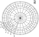
- FIGS. 1-5 Internal impingement cooling circuits or passages 10 of an exemplary gas turbine engine in which the cleaning methods and systems of the present disclosure may be employed are shown in FIGS. 1-5 .
- the internal impingement cooling circuits 10 may be positioned in a high pressure section of the turbine engine.
- an exemplary internal impingement cooling circuit 10 may be proximate (e.g., extending at least partially about) at least one first stage nozzle 14 and at least one first stage blade 16 and configured to impingement air cool at least one portion or surface 30 of at least one first stage shroud 18 associated with the at least one first stage blade 16 (i.e., the at least one shroud 18 is the component in which the internal impingement cooling circuit 10 is designed or configured to cool).
- the internal impingement cooling circuit 10 is only exemplary and the present disclosure may equally apply to other impingement cooled components of a turbine engine (i.e., components other than a first stage shroud 18) as recognized by one of ordinary skill in the art.
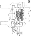
- the internal impingement cooling circuit 10 may include, define or form an internal cooling passageway 12 for directing a flow of cooling air to at least one back side surface 30 of at least one impingement baffle plate 20 positioned adjacent the cooled component (i.e., the at least one shroud 18), as shown in FIGS. 1 and 2 .
- the internal cooling passageway 12 of the impingement cooling circuit 10 feeds air to the baffle plate 20 that, ultimately, impinges air onto the backside 30 of the shroud 18 to cool the shroud 18.
- the cooling passageway 12 may extend generally in a forward-to-aft direction.
- the internal cooling passageway 12 may be provided or formed between an outer or exterior wall or casing 50 and an inner wall or casing 52 of the engine, as shown in FIG. 1 .
- the outer wall 50 of the engine may thereby isolate or otherwise prevent the internal cooling passageway 12 from being accessed from the exterior of the engine. In this way, the outer wall 50 of the engine must be breached or otherwise "opened” to provide an aperture for access or a passageway into the internal cooling passageway 12.
- the inner wall 52 may define or form, at least partially, a combustion pathway 54 extending from a fuel nozzle 56 that feeds fuel to the first stage of the engine (i.e., the first stage nozzles 14 and blades 16). In this way the cooling passageway 12 may extend at least partially about, along or exterior to the combustion pathway 54.
- the internal cooling passageway 12 may feed or otherwise be in fluid communication with at least one baffle plate 20 of the internal impingement cooling circuit 10.
- the baffle plate 20 may be coupled to or held by at least one hanger member 22 positioned proximate to a back side or exterior-facing surface 24 of the baffle plate 20.
- the hanger member 22 may "hold” or otherwise be coupled to a plurality of baffle plates 20.
- the hanger member 22 and the baffle plate 20 may form a pre-baffle cavity, plenum or space 34 between the hanger member 22 and the back side 24 of the baffle plate 20, as shown in FIG. 2 .
- the pre-baffle cavity 34 (and/or the internal cooling passageway 12) may be substantially airtight such that the cooling air (fed by the internal cooling passageway 12) is pressurized in the pre-baffle cavity 34.
- the cooling air in the pre-baffle cavity 34 and/or the internal cooling passageway 12, while the turbine engine is in service may operate at pressures up to about 69 Bar (1,000 psi).
- the hanger member 22 may include or define at least one aperture or passageway 42 extending through the hanger member 22 from the internal cooling passageway 12 to the pre-baffle cavity 34.
- the pre-baffle cavity 34 and the internal cooling passageway 12 may be in fluid communication via the at least one aperture 42.
- the at least one aperture 42 in the hanger member 22 may be configured to provide a sufficient flow rate, pressure and other characteristics or conditions of cooling air in the pre-baffle cavity 34 such that the baffle plate 20 effectively impingement air cools at least one backside, cooling side or portion 30 of the at least one shroud 18.
- the baffle plate 20 may include at least one (such as a plurality or array) of aperture or passageway 28 extending through the baffle plate 20 from the pre-baffle cavity 34 proximate to the back side 24 to a post-baffle cavity 36 proximate a front side 26 of the baffle plate 20.
- the front side 26 of the baffle plate 20 may substantially oppose the back side 24 of the baffle plate 20.
- the front side 26 of the baffle plate 20 may be proximate or adjacent to the surface or portion 30 of the component 18 in which the internal impingement cooling circuit 10 is designed or configured to impingement cool during service of the turbine engine.
- the post-baffle cavity 36 may extend between the front side 26 of the baffle plate 20 and the surface or portion 30 of the component 18 in which the internal impingement cooling circuit 10 is designed or configured to impingement cool.
- the impingement cooling circuit 10 may be designed or configured to impingement cool at least one shroud 18, and therefore the front side 26 of the baffle plate 20 (and the post-baffle cavity 36) is proximate or adjacent to a back side or portion 30 of the shroud 18 and otherwise configured such that cooling air passing through the plurality of apertures 28 of the baffle plate 20 into the post-baffle cavity 36 is impinged onto the back side 30 of the shroud 18.
- the plurality of apertures 28 in the baffle plate 20 may effectuate cooling of at least a surface 30 of a component 18 in the post-baffle cavity 36 by air impingement cooling to cool a component 18 that needs to be, or benefits from being, cooled.
- the impingement cooling circuit 10 may be designed to optimize or otherwise provide efficient, effective and/or above a pre-determined minimum level of cooling to the components 18 that the impingement cooling circuit 10 is designed to cool (e.g., at least one shroud, nozzle, etc.). For example, the delivery pressure of the cooling air in the pre-baffle cavity 34, the flow rate of the cooling air through the baffle plate 20, the number, arrangement/pattern, size, angulation, shape, etc.
- the velocity of the cooling air when it exits the back side 26 of the baffle plate 20 into the post-baffle cavity 36, the velocity of the cooling air when it impacts the surface or portion 30 of the impingement cooled component(s) 18 in the post-baffle cavity 36 (e.g., the back side 30 of at least one shroud 18), and the like may be designed to provide optimum impingement cooling efficiency to the impingement cooled component(s) 18.
- the methods and systems of cleaning turbine internal impingement cooling circuits may be configured to generate or establish suitable cleaning detergent flow geometry, characteristics or other conditions over the full area or surface 30 of the impingement cooled component 18 to clean dust, sand, debris 38 or other matter utilizing the impingement cooling circuits 10 that are configured, designed or optimized primarily or solely for cooling.
- the methods and systems of cleaning turbine internal impingement cooling circuits according to the present disclosure may be configured to utilize such designs or configuration for optimum cleaning.
- the impingement cooling circuits 10 (including the baffle plates 20) of the methods and systems of cleaning a turbine according to the present disclosure may include designing configuring and/or utilizing impingement cooling circuits 10 (including the baffle plates 20) designed, configured or otherwise suited to balance impingement cooling during turbine operation, and impingement cleaning of the impingement cooled-component 18.
- An impingement cooling circuit 10 configured, designed or optimized primarily or solely for cooling may include a baffle plate 20 with a back side 26 that is spaced within the range of about 1.27 mm to about 12.7 mm (0.05 - 0.5 inches) from the adjacent or proximate surface 30 of the impingement-cooled component 18.
- an impingement cooling circuit 10 configured, designed or optimized to balance impingement cooling and impingement cleaning of a turbine component may include a baffle plate 20 with a back side 26 that is spaced within the range of about 2.54 mm to about 6.35 mm (0.1 - 0.25 inches) from the adjacent or proximate surface 30 of the impingement-cooled component 18.
- a turbine engine typically includes a plurality of circumferentially arranged internal cooling circuits.
- the internal cooling circuit 10 shown in FIGS. 1 and 2 and described above represents one of numerous circuits that may be circumferentially arranged in a turbine.
- the circumferentially arranged internal cooling circuits 10 may thereby each include a passageway 12 for the cooling air, at least one baffle plate 20, and at least one component 18 air impingement cooled by the baffle plate 20. In this way, FIG.
- FIG. 3 graphically illustrates turbine engine with circumferentially arranged internal cooling circuits 10 each including a passageway 12 for the cooling air, a shroud hanger 22, a pair of baffle plates 20, and at least one shroud 18 cooled by the pair of baffle plates 20.
- the pair of baffle plates 20 may be supported or coupled to a hanger 20 such that a centerline or midline 21 of each hanger 20 is substantially aligned with the junction of the pair of baffle plates 20.
- the front side 26 of the baffle plates 20 may be substantially covered or overlaid with the built up matter 38, such as substantially completely covered by the built up matter 38.
- at least one aperture 28 of the baffle plates 20 may be partially or fully blocked, clogged or plugged with the built up matter 38.
- the methods and systems of cleaning turbine internal impingement cooling circuits according to the present disclosure may substantially remove such built up matter 38 on the front side 26 of the baffle plates 20 and/or in the apertures 28 of the baffle plates 20 of the internal impingement cooling circuits 10.
- the back side or impingement cooled components, surfaces or portions 26 of the shrouds 20 may include the built up matter 38.
- the back side or impingement cooled surfaces or portions 26 of the shrouds 20 may include bumps or raised portions that may tend to trap or otherwise accept the built up matter 38, as shown in FIG. 5 .
- the built up matter 38 on the impingement cooled surfaces or portions 26 of the cooled components 18 may insulate the components 18 or otherwise negatively affect the cooling efficiency of the impingement cooling via the baffle plates 20.
- cooled surfaces or portions 26 of the cooled components 18 may be substantially covered or overlaid with the built up matter 38 as shown in FIG. 5 , such as substantially completely covered by the built up matter 38.
- the methods and systems of cleaning turbine internal impingement cooling circuits according to the present disclosure, as described further below, may substantially remove such built up matter 38 on the cooled surfaces or portions 26 of the cooled components 18 of the internal impingement cooling circuits 10.
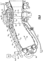
- FIGS. 6-10 illustrate methods and systems of cleaning turbine internal impingement cooling circuits according to the present disclosure for removal of the built up matter 38 on the cooled surfaces or portions 26 of the cooled components 18 of internal impingement cooling circuits 10 (as shown in FIG. 4 ) and/or the front side 26 of the baffle plates 20 of internal impingement cooling circuits 10 (as shown in FIG. 5 ) of turbine engines with detergent 64.
- the detergent 64 may be delivered to at least one baffle plate 20 that is used for impingement cooling in the turbine engine (e.g., in a high pressure section of a gas turbine engine), as shown in FIGS. 6 and 7 .
- the systems and methods are configured to introduce detergent 64 to a pre-baffle cavity 34 or otherwise proximate to a back side 24 of at least one baffle plate 20 of a turbine engine such that the detergent 64 passes through the apertures 28 in the baffle plate 20 and acts at least upon the component 18 that the baffle plate 20 is configured to air cool to clean built up matter 38 from the component 18.
- Detergent 64 may be delivered to the pre-baffle cavity 34 or proximate to the back side 24 of at least one baffle plate 20 via a detergent delivery mechanism 60, as shown in FIG. 6 .
- the detergent delivery mechanism 60 may provide a passageway or other detergent transportation mechanism or vehicle at least partially through the turbine internal impingement cooling circuits 10 to a pre-baffle cavity 34 or otherwise proximate to a back side 24 of at least one baffle plate 20 of a turbine engine.
- the detergent delivery mechanism 60 may be flexible, bendable, adaptable or adjustable hose, tube or tube-like mechanism that can be passed through one or more portions of the turbine engine and to a pre-baffle cavity 34 or otherwise proximate to a back side 24 of at least one baffle plate 20, and deliver detergent 64 thereto.
- the detergent delivery mechanism 60 may be configured to attach, mate or otherwise couple with the at least one aperture 62 in at least one hanger mechanism 22 from the internal cooling passageway 12 to provide detergent 64 to the at least one aperture 62 and, ultimately, to the associated pre-baffle cavity 34 or otherwise proximate to a back side 24 of at least one baffle plate 20.
- the detergent delivery mechanism 60 may extend to at least one pre-baffle cavity 34 or otherwise proximate to a back side 24 of at least one baffle plate 20 of an impingement cooling circuit 10 to provide a flow of detergent 64 thereto by extending at least partially through an internal cooling passageway 12 of the impingement cooling circuit 10.
- the detergent delivery mechanism 60 may access the internal cooling passageway 12, or otherwise extend to or be configured to provide detergent 64 to at least one baffle cavity 34 or proximate to a back side 24 of at least one baffle plate 20, by through an outer wall or case 50 of the engine. For example, as shown in FIG.
- the detergent delivery mechanism 60 may extend through the outer wall or case 50 of the engine, through or along an internal cooling passageway 12, and to at least one aperture 62 in a corresponding hanger mechanism 22. However, the detergent delivery mechanism 60 may extend through an access or aperture 66 in the outer wall or case 50 of the engine and to at least one baffle cavity 34 or proximate to a back side 24 of at least one baffle plate 20 without passing through or into the internal cooling passageway 12.
- the detergent delivery mechanism 60 may transmit or provide detergent 64 to the internal impingement cooling circuits 10 of a turbine engine through at least one aperture 66 in the outer wall or case 50 of the engine. In this way, the cleaning systems and methods of the present disclosure allow cleaning of the engine without removal of the engine from service and/or substantial disassembly of the engine to perform the cleaning.
- the at least one aperture 66 in the outer wall or case 50 of the engine utilized by the detergent delivery mechanism 60 transmit or provide detergent 64 to at least one pre-baffle cavity 34 or otherwise proximate to a back side 24 of at least one baffle plate 20 of an impingement cooling circuit 10, such as through an associated internal cooling passageway 12, may be an already existing access port in the outer wall 50 (i.e., a port that is utilized by the turbine engine for a purpose different than cleaning of the internal impingement cooling circuits 10).
- the at least one aperture 66 in the outer wall or case 50 of the engine that the delivery mechanism 60 passes through may be a bore scope access port, fuel nozzle port or flange, ignitor port, instrumentation access port or any other pre-existing port of the engine.
- At least one part or mechanism utilizing the port 66 of the engine may be removed such that the port 66 is exposed or otherwise available to the delivery mechanism 60.
- at least a portion of a fuel nozzle may be removed from the respective aperture or port 66 in the outer wall 50 of the turbine engine and the delivery mechanism 60 may extend through the "open" port 66 and into the respective internal cooling passageway 12 (and, ultimately, to the respective at least one baffle cavity 34 or proximate to a back side 24 of at least one baffle plate 20.
- the at least one aperture 66 in the outer wall or case 50 of the engine utilized by the delivery mechanism 60 to provide detergent 64 to at least one baffle plate 20 may be an aperture 66 that is not pre-existing and/or that is for a purpose different other than cleaning of the internal impingement cooling circuits 10.
- detergent 64 may be passed through or otherwise delivered by the detergent delivery mechanism 60 to the baffle plate 20 such that the detergent 64 passes through the apertures 28 in the baffle plate 20 into the post-baffle cavity 36 and is impinged or otherwise physically acts at least upon the component 18 that the respective internal impingement cooling circuit 10 is configured to cool and that has become covered or includes matter 38 that was deposited thereon during service.
- the detergent 64 that passes into the post-baffle cavity 36 may also act upon the front side 26 of the baffle plate 20 to remove matter 38 that also built up thereon.
- methods and systems of cleaning turbine internal impingement cooling circuits according to the present disclosure utilize baffle plates 20 to generate an array of detergent cleaning jets in the post-baffle cavity 36 when detergent 64 is delivered to pre-baffle plenums/cavities 34 or otherwise proximate to a back side 24 of baffle plates 20 of an impingement cooling circuit 10 to clean matter 38 from at least the components 18 that the internal impingement cooling circuits 10 are configured to cool.
- the pressure, flow rate, temperature and other conditions or metrics of the detergent 64 delivered by the detergent delivery mechanism 60 into the post-baffle cavity 36 may be configured or controlled.
- the delivery mechanism 60 may be in fluid connection with a source of detergent 64 that feeds or otherwise provides the detergent 64 to the detergent delivery mechanism 60.
- the detergent source 62 may regulate at least one of the temperature and pressure of the detergent 64 delivered by the delivery mechanism 60 to the baffle plenums/cavities 34 or otherwise proximate to the back sides 24 of the baffle plates 20 and into the post-baffle cavity 36.
- Detergent 64 is delivered to the baffle plenums/cavities 34 or otherwise proximate to the back sides 24 of the baffle plates 20 by the detergent source 62 and the detergent delivery mechanism 60 at pressures within the range of about 0.07 Bar to about 69 Bar (1 psi - 1000 psi)) to clean matter 38 in the post-baffle cavity 36 (e.g., the components 18 that the internal impingement cooling circuits 10 are configured to cool and, potentially, the front side 26 of the baffle plates 20).
- detergent 64 may be delivered to the pre-baffle plenums/cavities 34 or otherwise proximate to the back sides 24 of the baffle plates 20 by the detergent source 62 and the detergent delivery mechanism 60 at lower pressure such that the detergent 64 is a substantially passive or stagnant fluid in the pre-baffle cavity 34 or otherwise proximate to the back side 24 of the baffle 20.
- the effectiveness and/or efficiency of the jets of detergent 64 in the post-baffle cavity 36 in cleaning matter 38 built up on the components 18 that the internal impingement cooling circuits 10 are configured to cool (and, potentially, the front sides 26 of the baffle plates 20 of the internal impingement cooling circuits 10), characteristics or metrics of the jets may play a role.
- the angle of impact of the jets of detergent 64 in the post-baffle cavity 36 may be configured to generate appropriate impact against the matter 38.
- the delivery very pressure and flow rate range of the detergent 64 into the pre-baffle plenums/cavities 34 or otherwise proximate to the back sides 24 of the baffle plates 20 by the detergent source 62 and the detergent delivery mechanism 60 may be configured to establish effective and/or efficient detergent jet geometry and pattern in the post-baffle cavities 36.
- Other factors that may affect detergent 64 cleaning may include the pattern of apertures 28 in the baffle plate 20, the flow rate of the detergent 64 through the baffle plate 20, the number of apertures 28 in the baffle plate 20, the velocity of the detergent 64 when it exits the baffle plate 20 into the post-baffle cavity 36, the velocity of the detergent 64 when it impacts the matter 38, and the shear stress generated in the matter 38 by the detergent 64.
- the delivery pressure and flow rate range of the detergent 64 into the pre-baffle plenums/cavities 34 or otherwise proximate to the back sides 24 of the baffle plates 20 by the detergent source 62 and the detergent delivery mechanism 60 may be configured to establish effective and/or efficient detergent jet geometry and pattern in the post-baffle cavities 36 for one or more particular impingement cooling circuit 10 such that the matter 38 built up on at least each impingement cooled surface or component 18 is cleaned uniformly over the full area thereof.
- the methods and systems of cleaning turbine internal impingement cooling circuits may also include passing material other than the cleaning detergent 64 through the at least one aperture 28 of the baffle plate(s) 20 such that it is impinged at least upon the component or surface 18 that the baffle plate(s) is configured to cool before and/or after utilizing the detergent 64.
- the methods and systems of the present disclosure may include passing at least one cycle of gases and/or liquids through the at least one aperture 28 of the baffle plate(s) 20 such that it/they is/are impinged at least upon the component or surface 18 that the baffle plate(s) is configured to cool before and/or after utilizing the detergent 64.
- the methods and systems of cleaning turbine internal impingement cooling circuits may include passing cycles of steam, detergent 64, and liquid water through the at least one apertures 28 of at least one baffle plate 20 such that they are each impinged at least upon the component or surface 18 that the at least one baffle plate is configured to cool.
- the methods and systems of cleaning turbine internal impingement cooling circuits according to the present disclosure may uniformly clean matter 38 from circumferentially arranged internal impingement cooling circuits 10, such as that illustrated in FIG. 3 .
- the detergent delivery mechanism 60 may extend proximate to each of the circumferentially arranged baffle plates 20 to provide detergent 64 thereto for impingement cleaning of matter 38 deposited on circumferentially arranged components 18.
- the detergent delivery mechanism 60 may be configured to introduce or provide detergent 64 to the pre-baffle cavity 34 or otherwise proximate to a back side 24 each of the circumferentially arranged baffle plates 20 of a turbine engine to effectuate uniform cleaning around the full circumference of the internal cooling passages 10 of a turbine engine.
- the turbine engine may be mounted or otherwise oriented with the propulsion shaft extending substantially vertically (such as during typical maintenance of turbine engines) and a substantially equal amount of detergent 64 (or delivery pressure of the detergent 64) may directed or introduced to the pre-baffle cavity 34 or otherwise proximate to a back side 24 each of the circumferentially arranged baffle plates 20 of the engine to substantially uniformly clean matter 38 from at least the components 18 that the internal impingement cooling circuits 10 of the engine are configured to impingement cool.
- the turbine engine may be mounted or otherwise oriented with the propulsion shaft extending substantially horizontal (such as during typical operation of turbine engines) and the amount of detergent 64 (or delivery pressure of the detergent 64) that is directed or introduced to the pre-baffle cavity 34 or otherwise proximate to a back side 24 each of the circumferentially arranged baffle plates 20 of the engine may be adjusted to compensate for gravity so as to effectuate similar detergent jet-component interactions around the full circumference of the engine to substantially uniformly clean matter 38 from at least the components 18.
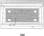
- FIGS. 8 and 9 The end result of the methods and systems of cleaning turbine internal impingement cooling circuits according to the present disclosure are shown in FIGS. 8 and 9 .
- the methods and systems of cleaning turbine internal impingement cooling circuits according to the present disclosure are effective in utilizing detergent 64 to impingement clean and thereby remove matter 38 that has built up on the impingement cooled surfaces 30 of the components 18 that the baffle plates 20 of the internal impingement cooling circuits 10 are configured to impingement cool, such as impingement air cool.
- impingement cool such as impingement air cool.
- the entirety of the impingement cooled surfaces 30 of the cooled components 18 may be substantially free of matter 38 after a cleaning operation such that the impingement cooled surfaces 30 are substantially similar to their as-manufactured condition and initial cooling efficiency (at least with respect to the lack of matter 38 thereon).
- the methods and systems of cleaning turbine internal impingement cooling circuits according to the present disclosure are effective in utilizing detergent 64 to remove matter 38 that has built up on the front sides 26 of the baffle plates 20 of the internal impingement cooling circuits 10 that are configured to impingement cool, such as impingement air cool. As shown in FIG.
- the entirety of the front sides 26 of the baffle plates 20 adjacent or proximate to the impingement cooled surfaces 30 of the cooled components 18 may be substantially free of matter 38 after a cleaning operation such that the front sides 26 of the baffle plates 20 are substantially similar to their as-manufactured condition and initial cooling efficiency (at least with respect to the lack of matter 38 thereon).
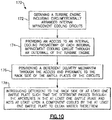
- an exemplary method of cleaning turbine internal impingement cooling circuits 170 may include obtaining 172 a turbine engine including circumferentially arranged internal impingement cooling circuits.
- Each internal impingement cooling circuit may include with a baffle plate configured to air impingement cool a respective circumferentially arranged component of the turbine engine.
- Each baffle plate may include a back side, a front side positioned proximate to the respective impingement cooled component, and apertures extending from the front side to the back side.
- the method of cleaning turbine internal impingement cooling circuits 170 may also include providing 174 an access to an internal cooling passageway of each of the circumferentially arranged internal impingement cooling circuits through an outer wall of the turbine engine, as shown in FIG. 10 .
- Providing 174 an access to an internal cooling passageway may include exposing or otherwise forming or providing a port or aperture through the outer wall of the turbine engine.
- the method of cleaning turbine internal impingement cooling circuits 170 may also include positioning 176 a detergent delivery mechanism through the access in the outer wall of the turbine, into the internal cooling passageway, and proximate to the back sides of the baffle plates.
- Positioning 176 a detergent delivery mechanism proximate to the back sides of the baffle plates may include positioning or arranging the detergent delivery mechanism proximate in fluid communication with a pre-baffle cavity associated with each baffle plate of each internal impingement cooling circuit, such as via an aperture in a hanger mechanism forming a pre-baffle cavity in concert with a respective baffle plate.
- the method of cleaning turbine internal impingement cooling circuits 170 may also include introducing 178 detergent to a back side of at least one baffle plate of the turbine engine such that the detergent passes through apertures in the at least one baffle plate and acts at least upon the at least one component that the at least one baffle plate is configured to air cool to clean matter from the at least one component.
- Introducing 178 the detergent may be accomplished via the detergent delivery mechanism.
- Introducing 178 detergent to a back side of at least one baffle plate of the turbine engine includes introducing the detergent such that the detergent passes through apertures in the at least one baffle plate and acts on the at least one component that the at least one baffle plate is configured to air cool and the front side of the at least one baffle plate to clean matter therefrom.
- Cycles of steam, detergent, and liquid water may be passed through the apertures in the at least one baffle plate and impinged at least upon the at least one component that the at least one baffle plate is configured to air cool to clean matter from the at least one component.
- the methods and systems of cleaning turbine internal impingement cooling circuits of the present disclosure were performed on internal impingement cooling circuits of an aircraft turbine engine that were configured to impingement cool the high-pressure shrouds of the engine.
- the back side(s) or rear surface(s) of the shrouds were therefore cooled by the impingement cooling air of the internal impingement cooling circuits during normal operation of the engine.
- particulate matter such as dust and debris
- was deposited or built up on the back side(s) or rear surface(s) of the shrouds thereby substantially reducing the heat transfer effectiveness of the impingement cooling circuits and leading to an undesirable increase in the flow path surface temperature of the shrouds during use of the engine.
- the example cooling methods and systems were performed to impingement clean the back side(s) or rear surface(s) of the shrouds, and the front sides of the baffle plates of the circuits, with detergent.
- Tests of the delivery methods and system of the present disclosure were performed, in part, to analyze the effect of detergent flow rate on detergent shroud wetting and, ultimately, shroud cleaning.
- the flow through the baffle was also analyzed tested to ensure sufficient pressure of the impingement fluid through the apertures in the baffle plate at the front side of the baffle plate, so that each jet in the arrangement was essentially normal to the surface of the shroud for all positions around the full circumference of the circumferentially arranged shroud assembly in the engine.
- the velocity of the impingement fluid through the shroud hanger apertures was about 1.3 m/s, and the velocity of the impingement fluid through the baffle apertures was about 0.4 m/s.
- testing was performed with the shroud removed from the shroud hanger.
- shrouds attached to the shroud hanger were tested to determine the uniformity of potential cleaning as a function of orientation or position around the full circumference of the engine (i.e., circumferentially arranged cooling circuits cooling circumferentially arranged shrouds).
- shrouds at three positions around the circumference of the engine were tested to determine the effect of position or orientation on detergent flow (i.e., simulating orientation of an engine oriented substantially horizontal).
- the shrouds were initially exposed separately to 4 detergent flow rates of 400, 600, 800, and 1000 ml/minute for 30 seconds.
- Detergent flow rates as high as 2000 ml/minute were also explored.
- the dust or matter-loaded surfaces of the shroud appeared darker when exposed to the detergent.
- Detergent wetting was used as a gauge of the uniformity of the exposure of the dust or matter on the shroud surface to the detergent during cleaning.
- a 30 second exposure of the 1000 ml/minute detergent flow rate was then tested on shrouds arranged or oriented for every clock position around the circumference of the engine (i.e., simulating orientation of an engine oriented substantially horizontal). For the 30 second exposure of the fluid at the 1000 ml/minute detergent flow rate, it was determined that almost all the surface area of every shroud was wetted by the detergent. The shrouds that showed the least wetting included those at the 2 o'clock, 5 o'clock, 7 o'clock, and 10 o'clock positions. It was noted that an exposure time greater than the tested 30 second exposure time would improve wetting uniformity about the circumference of the engine.
- Tests were also performed to assess the cleaning effectiveness of the delivery methods and system of the present disclosure on an actual aircraft engine assembly.
- a set of shrouds was removed from a wide-body aircraft engine that had operated for about 1000 cycles in environmental conditions that contained a relatively high concentration of airborne particulate, such as PM10 values of greater than about 80 micro grams per cubic meter, for example.
- the shrouds were then photographed, and assessed/measured for the degree of degradation, including flow path condition, cooling hole condition/performance, and the degree of particulate matter on the back side or impingement cooled surface of the shrouds.
- shrouds were then reassembled into the same engine position/configuration and the whole shroud assembly in the circumferential shroud hanger assembly was then subjected to a cleaning sequence of steam, detergent, and water, in order to test removal of the particulate matter from the back-side or impingement cooled surface of the shrouds.
- Cleaning detergent was delivered to the hanger members, baffle plates and, ultimately, the shrouds utilizing the delivery method or system of the present disclosure in order to generate uniform cleaning of the shrouds around the full circumference of the turbine engine.
- the detergent was delivered to the apertures in the hanger members such that a flow rate of about 1000 ml/minute was provided to each shroud (i.e., at the post-baffle cavity) for cleaning each shroud impingement cooled surface at every position around the full circumference of the engine.
- the flow rate was about 500 ml/minute through each hanger aperture.
- the flow conditions and flow rate delivered to the apertures of the shroud hanger members generated an arrangement of jets through the baffle plates and into the post-baffle cavity.
- cleaning tests were performed using a series of steam and/or detergent cycles to form a full cleaning cycle.
- Superheated steam was utilized through the system to pre-heat the part to be cleaned (i.e., the back side or impingement cooled surface of the shrouds), and detergent was utilized through the system to selectively dissolve the oxide-based, chloride-based, sulfate-based, and carbon-based constituents of the foreign material built up on the shrouds.
- a first sequence included an application of superheated steam at a temperature of about 105° C for about 16 minutes.
- a second sequence included an application of about 35-times diluted Citranox® at a flow rate of about 1000 mL/min for each shroud, at a temperature of greater than about 70° C for a duration of about 5 minutes. After the application of Citranox®, an application of superheated steam at temperature of greater than about 105° C for about 16 minutes was utilized.
- a third sequence included an application of about 35-times diluted Citranox® at a flow rate of about 1000 mL/min for each shroud, at a temperature of about 80° C for a duration of about 5 minutes, and an application of superheated steam at temperature of greater than about 105° C and for a duration of about 16 minutes.
- a fourth sequence included an application of about 35-times diluted Citranox® at a flow rate of about 1000 mL/min for each shroud, at a temperature of greater than about 70° C for a duration of about 5 minutes.
- a fourth sequence included an application of water at a flow rate of about 1000 mL/min for each shroud, at a temperature of about 20° C for a duration of about 20 minutes. As there were forty (40) total shrouds in the full circumferential engine assembly, the total flow rate of detergent delivered to the engine to generate uniform circumferential cleaning was about 40,000 mL/min.
- the shrouds were removed from the turbine engine and examined after drying. For example, the condition of the shrouds were assessed and/or measured, including the flow path condition, cooling aperture condition/performance, and the degree of particulate matter on the back side or impingement cooled surface of the shrouds.
- the cleaning system and method provided substantially uniform distribution of detergent over the whole rear or impingement cooled surface of the shrouds. It was also found that the cleaning system and method provided substantially uniform removal of dust, debris or particulate matter on the impingement cooled surface using the cleaning sequence described below. For example, it was determined that more than about 85 percent by mass of the original dust or particulate matter had been removed from the shrouds, and there was uniform removal of the dust over the full surface of each shroud. It was thereby concluded that the arrangement of detergent cleaning jets, the flow rate of detergent, and the cleaning cycles used to clean the shrouds within the engine had provided uniform cleaning of the shrouds.
Landscapes
- Engineering & Computer Science (AREA)
- Mechanical Engineering (AREA)
- General Engineering & Computer Science (AREA)
- Manufacturing & Machinery (AREA)
- Transportation (AREA)
- Aviation & Aerospace Engineering (AREA)
- Turbine Rotor Nozzle Sealing (AREA)
- Cleaning By Liquid Or Steam (AREA)
Claims (15)
- Procédé de nettoyage d'un turbomoteur comprenant au moins un circuit de refroidissement interne par soufflage (10) avec un déflecteur (20) configuré pour refroidir à l'air un composant du turbomoteur, le procédé consistant à :
introduire un détergent (64) sur le côté arrière (24) d'un déflecteur (20) du turbomoteur de sorte que le détergent passe à travers au moins une ouverture (28) du déflecteur (20) et agisse au moins sur le composant (18) pour lequel le déflecteur (20) est configuré pour le refroidissement par soufflage d'air afin de nettoyer le composant (18). - Procédé de nettoyage selon la revendication 1, dans lequel l'introduction de détergent (64) sur le côté arrière (24) d'un déflecteur (20) du turbomoteur comprend l'introduction de détergent dans une cavité de pré-déflecteur (34) placée à proximité de la face arrière (24) du déflecteur (20).
- Procédé de nettoyage selon la revendication 1 ou 2, comprenant en outre l'accès au côté arrière (24) du déflecteur (20) du turbomoteur par un orifice (66) dans une paroi extérieure (50) du turbomoteur.
- Procédé de nettoyage selon la revendication 3, dans lequel l'orifice (66) dans la paroi extérieure (50) du turbomoteur crée un passage vers un canal d'air de refroidissement interne (12) d'un circuit de refroidissement par soufflage d'air interne respectif (10) qui alimente le déflecteur (20) en air pour refroidir à l'air le composant (18).
- Procédé de nettoyage selon la revendication 3 ou 4, dans lequel l'orifice (66) est une ouverture dans un carter extérieur (52) du turbomoteur configuré pour loger une conduite de carburant couplée à un gicleur de carburant.
- Procédé de nettoyage selon l'une quelconque des revendications 3 à 5, dans lequel l'accès à un côté arrière (24) d'un déflecteur (20) du turbomoteur par un orifice (66) dans une paroi extérieure (50) du turbomoteur comprend la mise en place d'un mécanisme de distribution de détergent (66) à travers l'orifice et à proximité du côté arrière (24) du déflecteur (20).
- Procédé de nettoyage selon l'une quelconque des revendications 1 à 6, dans lequel le composant est un carénage (18) couplé à un support de carénage (22) positionné au moins partiellement sur le côté arrière (30) du carénage (18).
- Procédé de nettoyage selon la revendication 7, dans lequel le détergent (64) passe à travers au moins une ouverture (42) dans le support (22) et est introduit dans une cavité de pré-déflecteur (34) formée entre le support (22) et le côté arrière (30) du carénage (18).
- Procédé de nettoyage selon l'une quelconque des revendications précédentes, dans lequel le détergent agit sur un côté avant (26) du déflecteur (20) qui fait sensiblement face au composant (18) pour lequel le déflecteur (20) est configuré pour le refroidissement par soufflage d'air.
- Procédé de nettoyage selon l'une quelconque des revendications précédentes, dans lequel le détergent (64) comprend un réactif acide à base d'eau comprenant un agent tensioactif organique et un inhibiteur de corrosion conçus pour dissoudre sélectivement au moins l'une des espèces à base de sulfate, de chlorure et de carbonate tout en étant sensiblement non réactifs avec le matériau formant le composant (18).
- Procédé de nettoyage selon l'une quelconque des revendications précédentes, dans lequel les circuits de refroidissement internes par soufflage (10) comprennent une pluralité de circuits de refroidissement disposés de manière circonférentielle, chacun comprenant un déflecteur (20) configuré pour refroidir un composant respectif parmi les composants (18) disposés de manière circonférentielle comprenant en outre l'introduction sensiblement simultanée de détergent sur le côté arrière (24) d'une pluralité de déflecteurs (20) disposés de manière circonférentielle de telle sorte que le détergent passe à travers des ouvertures (28) dans les déflecteurs (20) et agit au moins sur le sens circonférentiel respectif des composants agencés (18) que les déflecteurs (20) sont configurés pour refroidir à l'air.
- Procédé de nettoyage selon l'une quelconque des revendications précédentes, consistant en outre à introduire du détergent sur le côté arrière d'un déflecteur du turbomoteur de sorte que le détergent passe à travers une pluralité d'ouvertures dans le déflecteur pour former une pluralité de jets discrets de détergent qui agissent au moins sur le composant que le déflecteur est configuré pour refroidir par soufflage d'air afin de nettoyer le composant.
- Système de nettoyage d'un turbomoteur, le système comprenant un turbomoteur, qui comprend au moins un circuit de refroidissement interne par soufflage (10) avec un passage de refroidissement interne (12) en communication avec un déflecteur (20) qui est configuré pour refroidir à l'air un composant (18) du turbomoteur, le système comprenant en outre :un mécanisme de distribution de détergent (66) s'étendant à travers une ouverture dans la paroi extérieure (50) de la turbine et à proximité d'un côté arrière (24) du déflecteur (20) ; etune source (62) d'un détergent (64) comprenant un réactif acide à base d'eau avec un agent tensioactif organique et un inhibiteur de corrosion en communication fluidique avec le mécanisme de distribution de détergent.
- Système selon la revendication 13, dans lequel le composant est un carénage (18) couplé à un support de carénage (22) positionné au moins partiellement sur la face arrière (30) du carénage (18), et dans lequel le mécanisme de distribution de détergent se prolonge jusqu'à une ouverture (28) dans le support de carénage (22) pour délivrer le détergent dans une cavité de pré-déflecteur (34) formée entre le support de carénage (22) et le côté arrière (24) du déflecteur (20).
- Système selon la revendication 13 ou 14, dans lequel le mécanisme de distribution de détergent s'étend jusqu'à une cavité de pré-déflecteur (34) qui est proche du côté arrière (24) du déflecteur (20).
Applications Claiming Priority (1)
| Application Number | Priority Date | Filing Date | Title |
|---|---|---|---|
| US14/621,465 US9957066B2 (en) | 2015-02-13 | 2015-02-13 | Detergent delivery methods and systems for turbine engines |
Publications (2)
| Publication Number | Publication Date |
|---|---|
| EP3061923A1 EP3061923A1 (fr) | 2016-08-31 |
| EP3061923B1 true EP3061923B1 (fr) | 2019-07-31 |
Family
ID=55409692
Family Applications (1)
| Application Number | Title | Priority Date | Filing Date |
|---|---|---|---|
| EP16154844.1A Active EP3061923B1 (fr) | 2015-02-13 | 2016-02-09 | Procédés et systèmes de distribution de détergent pour moteurs à turbine |
Country Status (6)
| Country | Link |
|---|---|
| US (2) | US9957066B2 (fr) |
| EP (1) | EP3061923B1 (fr) |
| JP (1) | JP2016148327A (fr) |
| CN (1) | CN105888746B (fr) |
| BR (1) | BR102016001459A2 (fr) |
| CA (1) | CA2919240C (fr) |
Families Citing this family (36)
| Publication number | Priority date | Publication date | Assignee | Title |
|---|---|---|---|---|
| US9926517B2 (en) | 2013-12-09 | 2018-03-27 | General Electric Company | Cleaning solution and methods of cleaning a turbine engine |
| US9932854B1 (en) * | 2013-12-09 | 2018-04-03 | General Electric Company | Methods of cleaning a hot gas flowpath component of a turbine engine |
| BR102016021259B1 (pt) | 2015-10-05 | 2022-06-14 | General Electric Company | Método e soluções de limpeza de um motor de turbina e composição de reagente |
| US20170204739A1 (en) | 2016-01-20 | 2017-07-20 | General Electric Company | System and Method for Cleaning a Gas Turbine Engine and Related Wash Stand |
| US10005111B2 (en) | 2016-01-25 | 2018-06-26 | General Electric Company | Turbine engine cleaning systems and methods |
| EP3504011B1 (fr) | 2016-09-30 | 2024-10-30 | General Electric Company | Système de lavage à l'eau et procédé de lavage d'un moteur à turbine à gaz |
| US11174751B2 (en) * | 2017-02-27 | 2021-11-16 | General Electric Company | Methods and system for cleaning gas turbine engine |
| US10731508B2 (en) | 2017-03-07 | 2020-08-04 | General Electric Company | Method for cleaning components of a turbine engine |
| US20180313225A1 (en) * | 2017-04-26 | 2018-11-01 | General Electric Company | Methods of cleaning a component within a turbine engine |
| US10871082B2 (en) * | 2018-01-02 | 2020-12-22 | General Electric Company | In situ foam generation within a turbine engine |
| US11371385B2 (en) | 2018-04-19 | 2022-06-28 | General Electric Company | Machine foam cleaning system with integrated sensing |
| US10907501B2 (en) * | 2018-08-21 | 2021-02-02 | General Electric Company | Shroud hanger assembly cooling |
| US11707819B2 (en) | 2018-10-15 | 2023-07-25 | General Electric Company | Selectively flexible extension tool |
| US12194620B2 (en) | 2018-10-15 | 2025-01-14 | Oliver Crisipin Robotics Limited | Selectively flexible extension tool |
| EP3667031A1 (fr) * | 2018-12-14 | 2020-06-17 | ABB Turbo Systems AG | Turbine à gaz avec dispositif de nettoyage ayant des injecteurs spécifiques |
| US11702955B2 (en) | 2019-01-14 | 2023-07-18 | General Electric Company | Component repair system and method |
| CN110064615B (zh) * | 2019-05-14 | 2022-07-22 | 中国航发沈阳发动机研究所 | 一种流道清洗装置及清洗方法 |
| US12405187B2 (en) | 2019-10-04 | 2025-09-02 | General Electric Company | Insertion apparatus for use with rotary machines |
| US11692650B2 (en) | 2020-01-23 | 2023-07-04 | General Electric Company | Selectively flexible extension tool |
| US11752622B2 (en) | 2020-01-23 | 2023-09-12 | General Electric Company | Extension tool having a plurality of links |
| US11613003B2 (en) | 2020-01-24 | 2023-03-28 | General Electric Company | Line assembly for an extension tool having a plurality of links |
| US11371437B2 (en) | 2020-03-10 | 2022-06-28 | Oliver Crispin Robotics Limited | Insertion tool |
| US12091981B2 (en) | 2020-06-11 | 2024-09-17 | General Electric Company | Insertion tool and method |
| US11555413B2 (en) | 2020-09-22 | 2023-01-17 | General Electric Company | System and method for treating an installed and assembled gas turbine engine |
| US12504616B2 (en) | 2021-01-08 | 2025-12-23 | General Electric Company | Insertion tool |
| US12416800B2 (en) | 2021-01-08 | 2025-09-16 | General Electric Company | Insertion tool |
| US11654547B2 (en) | 2021-03-31 | 2023-05-23 | General Electric Company | Extension tool |
| US12602808B2 (en) | 2021-07-13 | 2026-04-14 | General Electric Company | Method for inspecting an object |
| US12586226B2 (en) | 2021-07-13 | 2026-03-24 | General Electric Company | Method for inspecting an object |
| US12031446B2 (en) | 2022-03-29 | 2024-07-09 | General Electric Company | Turbine engine servicing tool and method for using thereof |
| US12269074B2 (en) | 2022-04-13 | 2025-04-08 | General Electric Company | System and method for cleaning turbine components |
| US12610116B2 (en) | 2022-11-11 | 2026-04-21 | General Electric Company | Inspection systems and methods employing directional light for enhanced imaging |
| US12318801B2 (en) | 2022-11-14 | 2025-06-03 | General Electric Company | Force-balancing spray nozzle devices |
| US12186848B1 (en) | 2024-01-26 | 2025-01-07 | General Electric Company | Method and apparatus for servicing engines |
| US12195202B1 (en) | 2024-01-26 | 2025-01-14 | General Electric Company | System and method for servicing aircraft engines |
| US12409571B1 (en) | 2024-03-08 | 2025-09-09 | General Electric Company | Snake-arm robot and joint therefor |
Family Cites Families (37)
| Publication number | Priority date | Publication date | Assignee | Title |
|---|---|---|---|---|
| GB758530A (en) | 1953-11-10 | 1956-10-03 | Napier & Son Ltd | Improvements relating to the cleaning of air compressors of the centrifugal type |
| US4167193A (en) | 1977-10-11 | 1979-09-11 | Magnus Harve W | Apparatus for cleaning jet engine nozzles |
| JPS54108116A (en) * | 1978-02-14 | 1979-08-24 | Tech Res & Dev Inst Of Japan Def Agency | Contamination preventer for blades of gas turbine engine |
| US4377420A (en) | 1980-03-06 | 1983-03-22 | United Technologies Corporation | Removal of carbonaceous material from gas turbine cavities |
| JPS63230907A (ja) * | 1987-03-20 | 1988-09-27 | Hitachi Ltd | ガスタ−ビン |
| AT392285B (de) | 1989-08-11 | 1991-02-25 | Lang Chem Tech Prod | Reinigungsmittel fuer kompressoren |
| DE4120305C1 (fr) | 1991-06-20 | 1992-08-27 | Mtu Muenchen Gmbh | |
| JP2872849B2 (ja) | 1991-12-20 | 1999-03-24 | 東北電力株式会社 | ガスタービン空気圧縮機用洗浄剤組成物 |
| US5385014A (en) | 1992-09-11 | 1995-01-31 | Aeronautical Accessories, Inc. | Valve and method of valve use while washing a compressor in an aircraft engine |
| US6394108B1 (en) | 1999-06-29 | 2002-05-28 | John Jeffrey Butler | Inside out gas turbine cleaning method |
| US6311704B1 (en) | 2000-03-03 | 2001-11-06 | Hydrochem Industrial Services | Methods and apparatus for chemically cleaning turbines |
| US6630198B2 (en) | 2001-01-19 | 2003-10-07 | General Electric Co. | Methods and apparatus for washing gas turbine engines |
| US6530744B2 (en) * | 2001-05-29 | 2003-03-11 | General Electric Company | Integral nozzle and shroud |
| US6546733B2 (en) * | 2001-06-28 | 2003-04-15 | General Electric Company | Methods and systems for cooling gas turbine engine combustors |
| AU2003259174A1 (en) | 2002-07-24 | 2004-02-09 | Mark D. Hughes | Methods and compositions for on-line gas turbine cleaning |
| US6883527B2 (en) | 2002-07-24 | 2005-04-26 | General Electric Company | Method for robotically cleaning compressor blading of a turbine |
| US7065955B2 (en) | 2003-06-18 | 2006-06-27 | General Electric Company | Methods and apparatus for injecting cleaning fluids into combustors |
| US7531048B2 (en) * | 2004-10-19 | 2009-05-12 | Honeywell International Inc. | On-wing combustor cleaning using direct insertion nozzle, wash agent, and procedure |
| US7115171B2 (en) | 2004-12-27 | 2006-10-03 | General Electric Company | Method for removing engine deposits from turbine components and composition for use in same |
| WO2006131689A1 (fr) | 2005-06-07 | 2006-12-14 | Reckitt Benckiser Inc | Améliorations des compositions organiques ou les concernant |
| US20070039175A1 (en) | 2005-07-19 | 2007-02-22 | General Electric Company | Methods for repairing turbine engine components |
| WO2007027522A2 (fr) | 2005-08-29 | 2007-03-08 | Advanced Technology Materials, Inc. | Composition et procede destines au retrait d'une couche epaisse de resine photosensible |
| EP1983075A1 (fr) | 2007-04-20 | 2008-10-22 | Siemens Aktiengesellschaft | Couches de céramique à base de polymère destinées à la protection de surfaces contre les ions fluorure lors d'un processus de nettoyage |
| US7828905B2 (en) * | 2007-05-04 | 2010-11-09 | Ecolab Inc. | Cleaning compositions containing water soluble magnesium compounds and methods of using them |
| DE102008019892A1 (de) | 2008-04-21 | 2009-10-29 | Mtu Aero Engines Gmbh | Verfahren zum Reinigen eines Flugtriebwerks |
| US8845819B2 (en) | 2008-08-12 | 2014-09-30 | General Electric Company | System for reducing deposits on a compressor |
| WO2010054132A2 (fr) | 2008-11-06 | 2010-05-14 | General Electric Company | Système et procédé de lavage de moteur |
| US8361237B2 (en) | 2008-12-17 | 2013-01-29 | Air Products And Chemicals, Inc. | Wet clean compositions for CoWP and porous dielectrics |
| US8303243B2 (en) | 2009-01-15 | 2012-11-06 | Pratt & Whitney Canada Corp. | Turbine wash port for a gas turbine engine |
| PL217602B1 (pl) * | 2010-03-18 | 2014-08-29 | Gen Electric | Urządzenie wieszaka tarczy wzmacniającej turbiny do gazowego silnika turbinowego |
| DE102010045869A1 (de) | 2010-08-03 | 2012-02-23 | Mtu Aero Engines Gmbh | Reinigung einer Turbomaschinenstufe |
| US8535449B2 (en) | 2011-06-22 | 2013-09-17 | Envirochem Solutions Llc | Use of coke compositions for on-line gas turbine cleaning |
| CA2856816A1 (fr) * | 2011-11-30 | 2013-06-06 | Basf Se | Composition pour dissoudre et/ou inhiber un depot de tartre sur une surface d'un systeme |
| DE102012002275A1 (de) | 2012-02-06 | 2013-08-08 | Rolls-Royce Deutschland Ltd & Co Kg | Vorrichtung und Verfahren zur Bearbeitung von Hochdruckturbinenschaufeln einer Gasturbine |
| US9206740B2 (en) | 2013-01-04 | 2015-12-08 | Honeywell International Inc. | Liquid injection inlet particle separator systems and methods |
| US9523287B2 (en) | 2013-01-18 | 2016-12-20 | General Electric Company | Cooling hole cleaning method and apparatus |
| US20150159122A1 (en) | 2013-12-09 | 2015-06-11 | General Electric Company | Cleaning solution and methods of cleaning a turbine engine |
-
2015
- 2015-02-13 US US14/621,465 patent/US9957066B2/en active Active
-
2016
- 2016-01-22 BR BR102016001459A patent/BR102016001459A2/pt not_active Application Discontinuation
- 2016-01-28 CA CA2919240A patent/CA2919240C/fr not_active Expired - Fee Related
- 2016-02-04 CN CN201610079275.8A patent/CN105888746B/zh active Active
- 2016-02-04 JP JP2016019409A patent/JP2016148327A/ja active Pending
- 2016-02-09 EP EP16154844.1A patent/EP3061923B1/fr active Active
-
2018
- 2018-03-29 US US15/939,525 patent/US20180237163A1/en not_active Abandoned
Non-Patent Citations (1)
| Title |
|---|
| None * |
Also Published As
| Publication number | Publication date |
|---|---|
| CN105888746A (zh) | 2016-08-24 |
| CA2919240A1 (fr) | 2016-08-13 |
| JP2016148327A (ja) | 2016-08-18 |
| EP3061923A1 (fr) | 2016-08-31 |
| US9957066B2 (en) | 2018-05-01 |
| US20160236799A1 (en) | 2016-08-18 |
| CN105888746B (zh) | 2018-03-27 |
| BR102016001459A2 (pt) | 2016-10-11 |
| US20180237163A1 (en) | 2018-08-23 |
| CA2919240C (fr) | 2018-04-24 |
Similar Documents
| Publication | Publication Date | Title |
|---|---|---|
| EP3061923B1 (fr) | Procédés et systèmes de distribution de détergent pour moteurs à turbine | |
| US12442312B2 (en) | Methods and system for cleaning gas turbine engine | |
| EP3213828B1 (fr) | Système et procédé de nettoyage de composants de moteur à turbine à gaz | |
| EP3213827B1 (fr) | Détergent sec et procédé pour le nettoyage de composants de moteur à turbine a gaz | |
| EP1749976B1 (fr) | Turbine à gaz comprenant un dispositif de lavage | |
| US7531048B2 (en) | On-wing combustor cleaning using direct insertion nozzle, wash agent, and procedure | |
| CN108798800B (zh) | 清洗涡轮发动机内的部件的方法 | |
| JP5080076B2 (ja) | アクティブクリアランス制御のためのガスタービンエンジンリングの熱制御 | |
| US20100232929A1 (en) | Cooling arrangement for a turbine engine component | |
| EP3242003B1 (fr) | Appareil d'injection de liquide et ensemble compresseur le comprenant | |
| EP3978150B1 (fr) | Système et procédé de nettoyage de dépôt sur un composant d'un moteur à turbine à gaz assemblé monté sur aile | |
| US20110083701A1 (en) | Process to clean gas turbine fuel chamber components | |
| US20170175568A1 (en) | Acoustic Cleaning of Gas Turbine Engine Components | |
| Mund et al. | A review of gas turbine online washing systems | |
| US12404781B2 (en) | Systems for treating an installed and assembled gas turbine engine | |
| CN107605539B (zh) | 热传递装置和相关的涡轮翼型件 | |
| Oosting et al. | On Line Compressor Washing on Large Frame 9-FA Gas Turbines: Erosion on R0 Compressor Blade Leading Edge—Field Performance With a Novel On Line Wash System | |
| CN204469926U (zh) | 发动机清洗喷嘴及发动机清洗装置 | |
| CN114034143A (zh) | 一种自摆动的喷淋装置及工作方法 | |
| Fonzo | Practical experience with GT inlet cooling. |
Legal Events
| Date | Code | Title | Description |
|---|---|---|---|
| PUAI | Public reference made under article 153(3) epc to a published international application that has entered the european phase |
Free format text: ORIGINAL CODE: 0009012 |
|
| AK | Designated contracting states |
Kind code of ref document: A1 Designated state(s): AL AT BE BG CH CY CZ DE DK EE ES FI FR GB GR HR HU IE IS IT LI LT LU LV MC MK MT NL NO PL PT RO RS SE SI SK SM TR |
|
| AX | Request for extension of the european patent |
Extension state: BA ME |
|
| STAA | Information on the status of an ep patent application or granted ep patent |
Free format text: STATUS: REQUEST FOR EXAMINATION WAS MADE |
|
| 17P | Request for examination filed |
Effective date: 20170228 |
|
| RBV | Designated contracting states (corrected) |
Designated state(s): AL AT BE BG CH CY CZ DE DK EE ES FI FR GB GR HR HU IE IS IT LI LT LU LV MC MK MT NL NO PL PT RO RS SE SI SK SM TR |
|
| RIC1 | Information provided on ipc code assigned before grant |
Ipc: F01D 25/00 20060101AFI20181218BHEP |
|
| GRAP | Despatch of communication of intention to grant a patent |
Free format text: ORIGINAL CODE: EPIDOSNIGR1 |
|
| STAA | Information on the status of an ep patent application or granted ep patent |
Free format text: STATUS: GRANT OF PATENT IS INTENDED |
|
| INTG | Intention to grant announced |
Effective date: 20190213 |
|
| GRAS | Grant fee paid |
Free format text: ORIGINAL CODE: EPIDOSNIGR3 |
|
| GRAA | (expected) grant |
Free format text: ORIGINAL CODE: 0009210 |
|
| STAA | Information on the status of an ep patent application or granted ep patent |
Free format text: STATUS: THE PATENT HAS BEEN GRANTED |
|
| AK | Designated contracting states |
Kind code of ref document: B1 Designated state(s): AL AT BE BG CH CY CZ DE DK EE ES FI FR GB GR HR HU IE IS IT LI LT LU LV MC MK MT NL NO PL PT RO RS SE SI SK SM TR |
|
| REG | Reference to a national code |
Ref country code: CH Ref legal event code: EP Ref country code: GB Ref legal event code: FG4D |
|
| REG | Reference to a national code |
Ref country code: AT Ref legal event code: REF Ref document number: 1161116 Country of ref document: AT Kind code of ref document: T Effective date: 20190815 |
|
| REG | Reference to a national code |
Ref country code: IE Ref legal event code: FG4D |
|
| REG | Reference to a national code |
Ref country code: DE Ref legal event code: R096 Ref document number: 602016017563 Country of ref document: DE |
|
| REG | Reference to a national code |
Ref country code: NL Ref legal event code: FP |
|
| REG | Reference to a national code |
Ref country code: LT Ref legal event code: MG4D |
|
| REG | Reference to a national code |
Ref country code: AT Ref legal event code: MK05 Ref document number: 1161116 Country of ref document: AT Kind code of ref document: T Effective date: 20190731 |
|
| PG25 | Lapsed in a contracting state [announced via postgrant information from national office to epo] |
Ref country code: FI Free format text: LAPSE BECAUSE OF FAILURE TO SUBMIT A TRANSLATION OF THE DESCRIPTION OR TO PAY THE FEE WITHIN THE PRESCRIBED TIME-LIMIT Effective date: 20190731 Ref country code: SE Free format text: LAPSE BECAUSE OF FAILURE TO SUBMIT A TRANSLATION OF THE DESCRIPTION OR TO PAY THE FEE WITHIN THE PRESCRIBED TIME-LIMIT Effective date: 20190731 Ref country code: AT Free format text: LAPSE BECAUSE OF FAILURE TO SUBMIT A TRANSLATION OF THE DESCRIPTION OR TO PAY THE FEE WITHIN THE PRESCRIBED TIME-LIMIT Effective date: 20190731 Ref country code: HR Free format text: LAPSE BECAUSE OF FAILURE TO SUBMIT A TRANSLATION OF THE DESCRIPTION OR TO PAY THE FEE WITHIN THE PRESCRIBED TIME-LIMIT Effective date: 20190731 Ref country code: NO Free format text: LAPSE BECAUSE OF FAILURE TO SUBMIT A TRANSLATION OF THE DESCRIPTION OR TO PAY THE FEE WITHIN THE PRESCRIBED TIME-LIMIT Effective date: 20191031 Ref country code: LT Free format text: LAPSE BECAUSE OF FAILURE TO SUBMIT A TRANSLATION OF THE DESCRIPTION OR TO PAY THE FEE WITHIN THE PRESCRIBED TIME-LIMIT Effective date: 20190731 Ref country code: PT Free format text: LAPSE BECAUSE OF FAILURE TO SUBMIT A TRANSLATION OF THE DESCRIPTION OR TO PAY THE FEE WITHIN THE PRESCRIBED TIME-LIMIT Effective date: 20191202 Ref country code: BG Free format text: LAPSE BECAUSE OF FAILURE TO SUBMIT A TRANSLATION OF THE DESCRIPTION OR TO PAY THE FEE WITHIN THE PRESCRIBED TIME-LIMIT Effective date: 20191031 |
|
| PG25 | Lapsed in a contracting state [announced via postgrant information from national office to epo] |
Ref country code: IS Free format text: LAPSE BECAUSE OF FAILURE TO SUBMIT A TRANSLATION OF THE DESCRIPTION OR TO PAY THE FEE WITHIN THE PRESCRIBED TIME-LIMIT Effective date: 20191130 Ref country code: GR Free format text: LAPSE BECAUSE OF FAILURE TO SUBMIT A TRANSLATION OF THE DESCRIPTION OR TO PAY THE FEE WITHIN THE PRESCRIBED TIME-LIMIT Effective date: 20191101 Ref country code: LV Free format text: LAPSE BECAUSE OF FAILURE TO SUBMIT A TRANSLATION OF THE DESCRIPTION OR TO PAY THE FEE WITHIN THE PRESCRIBED TIME-LIMIT Effective date: 20190731 Ref country code: AL Free format text: LAPSE BECAUSE OF FAILURE TO SUBMIT A TRANSLATION OF THE DESCRIPTION OR TO PAY THE FEE WITHIN THE PRESCRIBED TIME-LIMIT Effective date: 20190731 Ref country code: ES Free format text: LAPSE BECAUSE OF FAILURE TO SUBMIT A TRANSLATION OF THE DESCRIPTION OR TO PAY THE FEE WITHIN THE PRESCRIBED TIME-LIMIT Effective date: 20190731 Ref country code: RS Free format text: LAPSE BECAUSE OF FAILURE TO SUBMIT A TRANSLATION OF THE DESCRIPTION OR TO PAY THE FEE WITHIN THE PRESCRIBED TIME-LIMIT Effective date: 20190731 |
|
| PG25 | Lapsed in a contracting state [announced via postgrant information from national office to epo] |
Ref country code: TR Free format text: LAPSE BECAUSE OF FAILURE TO SUBMIT A TRANSLATION OF THE DESCRIPTION OR TO PAY THE FEE WITHIN THE PRESCRIBED TIME-LIMIT Effective date: 20190731 |
|
| PG25 | Lapsed in a contracting state [announced via postgrant information from national office to epo] |
Ref country code: RO Free format text: LAPSE BECAUSE OF FAILURE TO SUBMIT A TRANSLATION OF THE DESCRIPTION OR TO PAY THE FEE WITHIN THE PRESCRIBED TIME-LIMIT Effective date: 20190731 Ref country code: PL Free format text: LAPSE BECAUSE OF FAILURE TO SUBMIT A TRANSLATION OF THE DESCRIPTION OR TO PAY THE FEE WITHIN THE PRESCRIBED TIME-LIMIT Effective date: 20190731 Ref country code: EE Free format text: LAPSE BECAUSE OF FAILURE TO SUBMIT A TRANSLATION OF THE DESCRIPTION OR TO PAY THE FEE WITHIN THE PRESCRIBED TIME-LIMIT Effective date: 20190731 Ref country code: IT Free format text: LAPSE BECAUSE OF FAILURE TO SUBMIT A TRANSLATION OF THE DESCRIPTION OR TO PAY THE FEE WITHIN THE PRESCRIBED TIME-LIMIT Effective date: 20190731 Ref country code: DK Free format text: LAPSE BECAUSE OF FAILURE TO SUBMIT A TRANSLATION OF THE DESCRIPTION OR TO PAY THE FEE WITHIN THE PRESCRIBED TIME-LIMIT Effective date: 20190731 |
|
| PG25 | Lapsed in a contracting state [announced via postgrant information from national office to epo] |
Ref country code: SK Free format text: LAPSE BECAUSE OF FAILURE TO SUBMIT A TRANSLATION OF THE DESCRIPTION OR TO PAY THE FEE WITHIN THE PRESCRIBED TIME-LIMIT Effective date: 20190731 Ref country code: CZ Free format text: LAPSE BECAUSE OF FAILURE TO SUBMIT A TRANSLATION OF THE DESCRIPTION OR TO PAY THE FEE WITHIN THE PRESCRIBED TIME-LIMIT Effective date: 20190731 Ref country code: SM Free format text: LAPSE BECAUSE OF FAILURE TO SUBMIT A TRANSLATION OF THE DESCRIPTION OR TO PAY THE FEE WITHIN THE PRESCRIBED TIME-LIMIT Effective date: 20190731 Ref country code: IS Free format text: LAPSE BECAUSE OF FAILURE TO SUBMIT A TRANSLATION OF THE DESCRIPTION OR TO PAY THE FEE WITHIN THE PRESCRIBED TIME-LIMIT Effective date: 20200224 |
|
| REG | Reference to a national code |
Ref country code: DE Ref legal event code: R097 Ref document number: 602016017563 Country of ref document: DE |
|
| PLBE | No opposition filed within time limit |
Free format text: ORIGINAL CODE: 0009261 |
|
| STAA | Information on the status of an ep patent application or granted ep patent |
Free format text: STATUS: NO OPPOSITION FILED WITHIN TIME LIMIT |
|
| PG2D | Information on lapse in contracting state deleted |
Ref country code: IS |
|
| PG25 | Lapsed in a contracting state [announced via postgrant information from national office to epo] |
Ref country code: IS Free format text: LAPSE BECAUSE OF FAILURE TO SUBMIT A TRANSLATION OF THE DESCRIPTION OR TO PAY THE FEE WITHIN THE PRESCRIBED TIME-LIMIT Effective date: 20191030 |
|
| 26N | No opposition filed |
Effective date: 20200603 |
|
| PG25 | Lapsed in a contracting state [announced via postgrant information from national office to epo] |
Ref country code: SI Free format text: LAPSE BECAUSE OF FAILURE TO SUBMIT A TRANSLATION OF THE DESCRIPTION OR TO PAY THE FEE WITHIN THE PRESCRIBED TIME-LIMIT Effective date: 20190731 |
|
| REG | Reference to a national code |
Ref country code: CH Ref legal event code: PL |
|
| REG | Reference to a national code |
Ref country code: BE Ref legal event code: MM Effective date: 20200229 |
|
| PG25 | Lapsed in a contracting state [announced via postgrant information from national office to epo] |
Ref country code: LU Free format text: LAPSE BECAUSE OF NON-PAYMENT OF DUE FEES Effective date: 20200209 Ref country code: MC Free format text: LAPSE BECAUSE OF FAILURE TO SUBMIT A TRANSLATION OF THE DESCRIPTION OR TO PAY THE FEE WITHIN THE PRESCRIBED TIME-LIMIT Effective date: 20190731 |
|
| PG25 | Lapsed in a contracting state [announced via postgrant information from national office to epo] |
Ref country code: CH Free format text: LAPSE BECAUSE OF NON-PAYMENT OF DUE FEES Effective date: 20200229 Ref country code: LI Free format text: LAPSE BECAUSE OF NON-PAYMENT OF DUE FEES Effective date: 20200229 |
|
| PG25 | Lapsed in a contracting state [announced via postgrant information from national office to epo] |
Ref country code: IE Free format text: LAPSE BECAUSE OF NON-PAYMENT OF DUE FEES Effective date: 20200209 |
|
| PG25 | Lapsed in a contracting state [announced via postgrant information from national office to epo] |
Ref country code: BE Free format text: LAPSE BECAUSE OF NON-PAYMENT OF DUE FEES Effective date: 20200229 |
|
| PG25 | Lapsed in a contracting state [announced via postgrant information from national office to epo] |
Ref country code: MT Free format text: LAPSE BECAUSE OF FAILURE TO SUBMIT A TRANSLATION OF THE DESCRIPTION OR TO PAY THE FEE WITHIN THE PRESCRIBED TIME-LIMIT Effective date: 20190731 Ref country code: CY Free format text: LAPSE BECAUSE OF FAILURE TO SUBMIT A TRANSLATION OF THE DESCRIPTION OR TO PAY THE FEE WITHIN THE PRESCRIBED TIME-LIMIT Effective date: 20190731 |
|
| PG25 | Lapsed in a contracting state [announced via postgrant information from national office to epo] |
Ref country code: MK Free format text: LAPSE BECAUSE OF FAILURE TO SUBMIT A TRANSLATION OF THE DESCRIPTION OR TO PAY THE FEE WITHIN THE PRESCRIBED TIME-LIMIT Effective date: 20190731 |
|
| P01 | Opt-out of the competence of the unified patent court (upc) registered |
Effective date: 20230414 |
|
| PGFP | Annual fee paid to national office [announced via postgrant information from national office to epo] |
Ref country code: NL Payment date: 20260121 Year of fee payment: 11 |
|
| PGFP | Annual fee paid to national office [announced via postgrant information from national office to epo] |
Ref country code: GB Payment date: 20260122 Year of fee payment: 11 |
|
| PGFP | Annual fee paid to national office [announced via postgrant information from national office to epo] |
Ref country code: DE Payment date: 20260121 Year of fee payment: 11 |
|
| PGFP | Annual fee paid to national office [announced via postgrant information from national office to epo] |
Ref country code: FR Payment date: 20260121 Year of fee payment: 11 |