EP3061973B1 - Vakuumpumpe - Google Patents
Vakuumpumpe Download PDFInfo
- Publication number
- EP3061973B1 EP3061973B1 EP16157019.7A EP16157019A EP3061973B1 EP 3061973 B1 EP3061973 B1 EP 3061973B1 EP 16157019 A EP16157019 A EP 16157019A EP 3061973 B1 EP3061973 B1 EP 3061973B1
- Authority
- EP
- European Patent Office
- Prior art keywords
- pair
- rotors
- gears
- pump
- vacuum pump
- Prior art date
- Legal status (The legal status is an assumption and is not a legal conclusion. Google has not performed a legal analysis and makes no representation as to the accuracy of the status listed.)
- Active
Links
Images


Classifications
-
- F—MECHANICAL ENGINEERING; LIGHTING; HEATING; WEAPONS; BLASTING
- F04—POSITIVE - DISPLACEMENT MACHINES FOR LIQUIDS; PUMPS FOR LIQUIDS OR ELASTIC FLUIDS
- F04C—ROTARY-PISTON, OR OSCILLATING-PISTON, POSITIVE-DISPLACEMENT MACHINES FOR LIQUIDS; ROTARY-PISTON, OR OSCILLATING-PISTON, POSITIVE-DISPLACEMENT PUMPS
- F04C25/00—Adaptations of pumps for special use of pumps for elastic fluids
- F04C25/02—Adaptations of pumps for special use of pumps for elastic fluids for producing high vacuum
-
- F—MECHANICAL ENGINEERING; LIGHTING; HEATING; WEAPONS; BLASTING
- F04—POSITIVE - DISPLACEMENT MACHINES FOR LIQUIDS; PUMPS FOR LIQUIDS OR ELASTIC FLUIDS
- F04C—ROTARY-PISTON, OR OSCILLATING-PISTON, POSITIVE-DISPLACEMENT MACHINES FOR LIQUIDS; ROTARY-PISTON, OR OSCILLATING-PISTON, POSITIVE-DISPLACEMENT PUMPS
- F04C18/00—Rotary-piston pumps specially adapted for elastic fluids
- F04C18/08—Rotary-piston pumps specially adapted for elastic fluids of intermeshing-engagement type, i.e. with engagement of co-operating members similar to that of toothed gearing
- F04C18/12—Rotary-piston pumps specially adapted for elastic fluids of intermeshing-engagement type, i.e. with engagement of co-operating members similar to that of toothed gearing of other than internal-axis type
- F04C18/14—Rotary-piston pumps specially adapted for elastic fluids of intermeshing-engagement type, i.e. with engagement of co-operating members similar to that of toothed gearing of other than internal-axis type with toothed rotary pistons
- F04C18/16—Rotary-piston pumps specially adapted for elastic fluids of intermeshing-engagement type, i.e. with engagement of co-operating members similar to that of toothed gearing of other than internal-axis type with toothed rotary pistons with helical teeth, e.g. chevron-shaped, screw type
-
- F—MECHANICAL ENGINEERING; LIGHTING; HEATING; WEAPONS; BLASTING
- F04—POSITIVE - DISPLACEMENT MACHINES FOR LIQUIDS; PUMPS FOR LIQUIDS OR ELASTIC FLUIDS
- F04C—ROTARY-PISTON, OR OSCILLATING-PISTON, POSITIVE-DISPLACEMENT MACHINES FOR LIQUIDS; ROTARY-PISTON, OR OSCILLATING-PISTON, POSITIVE-DISPLACEMENT PUMPS
- F04C29/00—Component parts, details or accessories of pumps or pumping installations, not provided for in groups F04C18/00 - F04C28/00
- F04C29/0042—Driving elements, brakes, couplings, transmissions specially adapted for pumps
- F04C29/005—Means for transmitting movement from the prime mover to driven parts of the pump, e.g. clutches, couplings, transmissions
- F04C29/0064—Magnetic couplings
-
- F—MECHANICAL ENGINEERING; LIGHTING; HEATING; WEAPONS; BLASTING
- F04—POSITIVE - DISPLACEMENT MACHINES FOR LIQUIDS; PUMPS FOR LIQUIDS OR ELASTIC FLUIDS
- F04C—ROTARY-PISTON, OR OSCILLATING-PISTON, POSITIVE-DISPLACEMENT MACHINES FOR LIQUIDS; ROTARY-PISTON, OR OSCILLATING-PISTON, POSITIVE-DISPLACEMENT PUMPS
- F04C18/00—Rotary-piston pumps specially adapted for elastic fluids
- F04C18/08—Rotary-piston pumps specially adapted for elastic fluids of intermeshing-engagement type, i.e. with engagement of co-operating members similar to that of toothed gearing
- F04C18/12—Rotary-piston pumps specially adapted for elastic fluids of intermeshing-engagement type, i.e. with engagement of co-operating members similar to that of toothed gearing of other than internal-axis type
- F04C18/126—Rotary-piston pumps specially adapted for elastic fluids of intermeshing-engagement type, i.e. with engagement of co-operating members similar to that of toothed gearing of other than internal-axis type with radially from the rotor body extending elements, not necessarily co-operating with corresponding recesses in the other rotor, e.g. lobes, Roots type
-
- F—MECHANICAL ENGINEERING; LIGHTING; HEATING; WEAPONS; BLASTING
- F04—POSITIVE - DISPLACEMENT MACHINES FOR LIQUIDS; PUMPS FOR LIQUIDS OR ELASTIC FLUIDS
- F04C—ROTARY-PISTON, OR OSCILLATING-PISTON, POSITIVE-DISPLACEMENT MACHINES FOR LIQUIDS; ROTARY-PISTON, OR OSCILLATING-PISTON, POSITIVE-DISPLACEMENT PUMPS
- F04C2240/00—Components
- F04C2240/40—Electric motor
Definitions
- the present invention relates to a vacuum pump.
- a vacuum pump is a pump which creates negative pressure inside a container by evacuating gas from the container.
- vacuum pumps There are various types of vacuum pumps.
- a vacuum pump is known which evacuates gas by rotating a pair of pump rotors, provided on a pair of opposite shafts, synchronously in opposite directions.
- a motor rotor having a permanent magnet provided on the outer periphery, or a motor rotor having a permanent magnet embedded on the inside thereof is provided on each of the pair of shafts, and a magnetic coupling is formed through a stator core by different magnetic pole faces of the motor rotors.
- This vacuum pump uses a magnetic coupling between the motor rotors to rotate the pair of pump rotors synchronously in opposite directions. Since this vacuum pump forms a magnetic coupling through the stator core, a magnetic circuit is formed not only between the two shafts but also inside the single shafts, which results in a weak magnetic coupling force.
- a gear which suppresses the loss of synchronization between the pair of pump rotors is mounted on each of the pair of shafts. Since the pump rotors are synchronized by means of the gears in order to compensate for the weak magnetic coupling force, the load applied to the gears is relatively large. Accordingly, the gears are increased in size to retain a relatively high strength. Moreover, to suppress wear due to contact etc. of the gears, it is conceivable to provide a space, filled with lubricating oil etc., separately from a motor chamber and a pump chamber and provide the gears inside that space. However, this aspect makes the structure of the vacuum pump complicated and causes an increase in size of the vacuum pump.
- a vacuum pump having an enhanced magnetic coupling force is also known.
- a motor rotor having a permanent magnet provided on the outer periphery is mounted on each of a pair of shafts, and a magnetic coupling is directly formed by different magnetic pole faces of the motor rotors without a stator core interposed therebetween. According to this vacuum pump, it is possible to rotate the two shafts synchronously in opposite directions without using a gear.
- WO 2004/031585 A1 was used as a basis for the preamble of claim 1 and discloses a screw pump which includes a pair of screw rotors having teeth which are held in mesh with each other for drawing and discharging a fluid by rotating the screw rotors synchronously in opposite directions.
- the teeth of the screw rotors have the same shape as each other and are coiled helically in opposite directions.
- the teeth of the screw rotors have an axial tooth profile which allows a pair of facing teeth surfaces of the screw rotors to be brought into contact with each other only at a pitch line when the pair of facing teeth surfaces are brought into contact with each other.
- the vacuum pump which directly forms a magnetic coupling, suctions a small solid, synchronization between the pump rotors may be lost as the solid is caught between the pump rotors, and the pump rotors may come into contact with each other. In this case, the vacuum pump may stop. Even if the solid is removed by the rotary force of the pump rotors, any contact between the pump rotors may result in damage to the pump rotors. In this case, the vacuum pump can no longer maintain its performance, and the vacuum pump may stop.
- a vacuum pump is provided as set forth in claim 1.
- the pair of gears come into contact with each other so as to resolve the loss of synchronization between the pair of pump rotors.
- contact between the pump rotors can be suppressed.
- the pair of motor rotors directly form a magnetic coupling and the magnetic coupling force is sufficiently large.
- the pair of pump rotors are synchronously rotated by the magnetic coupling force of the pair of motor rotors alone, and the pair of gears do not come into contact with each other. Accordingly, the strength required of the pair of gears is relatively small, so that the size of the pair of gears can be reduced. Moreover, since the pair of gears come into contact with each other infrequently and do not easily wear, it is not necessary to dispose the pair of gears in a space filled with lubricating oil, for example. Therefore, the vacuum pump can be simplified in structure and reduced in
- the pair of gears come into contact with each other before the pair of pump rotors come into contact with each other.
- the pair of pump rotors are synchronized.
- the pair of pump rotors can synchronously rotate while keeping out of contact with each other.
- the vacuum pump of one embodiment may further include armatures disposed outside the outer periphery of the pair of motor rotors, and the armatures may be disposed in an elliptical shape with a predetermined clearance kept to the outer periphery of the pair of motor rotors. Accordingly, the pair of motor rotors can directly form a magnetic coupling and produce a sufficiently large magnetic coupling force.
- the pair of gears may be disposed in a space not filled with a lubricant.
- the pair of gears may be disposed inside a pump chamber where the pair of pump rotors are disposed.
- the pair of gears may be disposed inside a motor chamber where the pair of motor rotors are disposed.
- the vacuum pump can be simplified in structure and reduced in size.
- At least one of the pair of gears may be formed of a self-lubricating material. At least one of the pair of gears may be formed of a resin. The surface of at least one of the pair of gears may be coated with a lubricant.
- FIG. 1 is a schematic cross-sectional view of the vacuum pump of one embodiment.
- a screw vacuum pump will be described as an example of a vacuum pump.
- the present invention is applicable not only to a screw vacuum pump but also to a synchronous opposite rotation-type vacuum pump such as a Roots pump.
- a vacuum pump 1000 of this embodiment is used, for example, to evacuate gas from a space where an object to be analyzed with a scanning electron microscope is installed.
- the vacuum pump 1000 can also be used for various other applications including evacuation of gas in semiconductor manufacturing equipment.
- the vacuum pump 1000 includes a drive motor unit 200, and a pair of pump rotor units 300, 400 which are driven to rotate by the drive motor unit 200.
- the pump rotor unit 300 includes a pump main shaft 310 and a screw-type pump rotor 312 mounted on the pump main shaft 310.
- the pump rotor unit 400 includes a pump main shaft 410 disposed facing the pump main shaft 310 and a screw-type pump rotor 412 mounted on the pump main shaft 410.
- the pump rotor 312 and the pump rotor 412 face each other. As shown in FIG. 1 , the screw of the pump rotor 312 and the screw of the pump rotor 412 are separated from each other with predetermined clearances S1, S2 kept therebetween.
- the pump rotor 312 and the pump rotor 412 are disposed inside a pump chamber 500 which is formed by an upper casing (not shown) and a lower casing 330.
- First ends of the pump main shafts 310, 410 are supported by bearings 340, 440.
- the pump main shafts 310, 410 are supported by bearings 342, 442 at a border part between the drive motor unit 200 and the pump rotor units 300, 400.
- Second ends of the pump main shafts 310, 410 protrude toward the drive motor unit 200 from the positions where the pump main shafts 310, 410 are supported by the bearings 342, 442.
- the drive motor unit 200 includes motor rotors 110, 210, a stator yoke 120, and gears 380, 480.
- the motor rotors 110, 210 are mounted on the second ends of the pump main shafts 310, 410, respectively.
- the motor rotor 110 and the motor rotor 210 face each other.
- the stator yoke 120 surrounds the motor rotors 110, 210.
- the gears 380, 480 are mounted on the pump main shafts 310, 410, respectively.
- the gear 380 and the gear 480 face each other.
- the motor rotors 110, 210, the stator yoke 120, and the gears 380, 480 are disposed inside a motor chamber 600 which is formed by a motor frame 130.
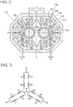
- FIG. 2 is a cross-sectional view showing the structure of the drive motor of one embodiment.
- FIG. 3 is a view showing the connection of the windings of the drive motor.
- the motor rotors 110, 210 have permanent magnets 112, 212 provided around their surfaces. Specifically, in this embodiment, the permanent magnets 112, 212 each have three pairs of poles, and six poles, S, N, S, N, S, and N, are provided around each of the motor rotors 110, 210.
- the vacuum pump including a surface permanent magnet (SPM) motor which has the permanent magnets 112, 212 provided around the surfaces of the motor rotors 110, 210 has been illustrated, but the present invention is not limited to this example.
- the present invention is also applicable to a vacuum pump including an interior permanent magnet (IPM) motor which has a permanent magnet embedded inside the motor rotor.
- the stator yoke 120 surrounds the motor rotors 110, 210 in an elliptical shape.
- the stator yoke 120 is provided with a plurality of armatures 122.
- the armatures 122 each include an armature iron core 124 and a winding 126 wound around the armature iron core 124.
- the armatures 122 are positioned by being fitted into the common stator yoke 120.
- the armatures 122 are disposed at a distance of a predetermined clearance ⁇ 1 from the outer peripheral surfaces of the motor rotors 110, 210.
- the armatures 122 are disposed in an elliptical shape with a predetermined clearance kept to the outer periphery of the pair of motor rotors 110, 210.
- Each winding 126 is divided into six slots, U, V, W, U', V', and W'.
- the windings U', V', and W' are opposite in phase to the windings U, V, and W, respectively.
- the windings U1, U2, V1, V2, and W1, W2 are connected in series, and they are windings with an equal number of turns.
- the windings U1, U1', V1, V1', W1, and W1' and the windings U2, U2', V2, V2', W2, and W2' are disposed symmetrically with respect to a line of symmetry B.
- the windings U1, U2, V1, V2, W1, and W2 and the windings U1', U2', V1', V2', W1', and W2' are disposed symmetrically with respect to a line of symmetry C.
- the winding 126 has the windings U1, U2 connected in series and the windings U1', U2', which are opposite in phase to the windings U1, U2, connected in series, and the windings U1, U2 and the windings U1', U2' are connected in parallel to constitute the U-phase.
- the motor rotors 110, 210 are disposed with a predetermined center distance t kept therebetween.
- the motor rotors 110, 210 have the permanent magnets 112, 212, which are magnetized in six poles, alternately as N and S at regular intervals, respectively provided on the outer periphery.
- each two poles facing each other across the line of symmetry C of the six-pole permanent magnets 112, 212 are used as a magnetic coupling.
- the motor rotors 110, 210 form a magnetic coupling by having their different magnetic pole faces facing each other, and synchronously rotate only in the opposite directions from each other.
- the outer peripheries of the motor rotors 110, 210 face each other with a predetermined clearance distance ⁇ 0 kept therebetween.
- the motor rotors 110, 210 directly face each other across a space, without a stator core, such as an iron core, interposed therebetween. That is, the vacuum pump 1000 of this embodiment is a vacuum pump in which the motor rotors 110, 210 directly form a magnetic coupling.
- too large a clearance between the motor rotors 110, 210 causes a decrease in magnetic coupling force.
- the drive motor unit 200 includes 12 armatures 122.
- the armatures 122 are disposed in groups of six poles so as to be symmetrical with respect to the line of symmetry C.
- the windings 126 are wound around the armature iron cores 124 in the same phase and in the opposite directions.
- an opposite-phase relation is established as the windings 126 at symmetrical positions are energized in the opposite directions.
- the drive motor unit 200 is driven as one motor. Since the drive motor unit 200 is driven as one three-phase motor, there may also be one drive power source device.
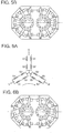
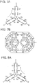
- FIG. 4A to FIG. 9A are views showing the flow of an electric current through the wirings connected as shown in FIG. 3 .
- FIG. 4B to FIG. 9B are views showing the flow of an electric current through the armature windings of the drive motor of FIG. 2 and the rotation of the pump rotors.
- the drive motor unit 200 According to the magnetic pole position of the motor rotors 110, 210, the drive motor unit 200 repeatedly switches energization in six ways as indicated by the arrows in FIG. 4A to FIG. 9A .
- the drive motor unit 200 continues rotation by rotating the motor rotors 110, 210 synchronously in opposite directions, the directions of the arrows in FIG. 4B to FIG. 9B .
- the number of the magnetic poles of the motor rotors 110, 210, the number of the armatures 122, and the combination thereof are not limited to those shown in this embodiment but are arbitrary.
- the number of the magnetic poles of each of the motor rotors 110, 210 may be four, and the number of the armatures 122 may be six.
- FIG. 10 is a view schematically showing the clearance between the teeth of the gears.
- FIG. 10 shows only a part of the gears 380, 480.
- the clearances between teeth 380a of the gear 380 and teeth 480a of the gear 480 are set to G1, G2.
- the clearances G1, G2 between the teeth 380a of the gear 380 and the teeth 480a of the gear 480 are backlash dimensions which satisfy the relation G1, G2 ⁇ S1, S2.
- the pump rotors 312, 412 and the gears 380, 480 are formed so as to satisfy the relation G1, G2 ⁇ S1, S2.
- the motor rotors 110, 210 directly form a magnet coupling between the opposite different magnetic poles, without an iron core interposed therebetween, and rotate synchronously in opposite directions.
- the gears 380, 480 can rotate without coming into contact with each other. Therefore, the vacuum pump 1000 can eliminate contact resistance of the gears 380, 480 and loss of grease or lubricating oil.
- this embodiment can provide the vacuum pump 1000 which suffers little gear loss and is highly efficient as well as capable of highspeed rotation.
- the vacuum pump 1000 of this embodiment can rotate the pump rotors 312, 412 synchronously in opposite directions without causing the pump rotors 312, 412 to come into contact with each other.
- the vacuum pump of this embodiment includes the gears 380, 480.
- the gears 380, 480 come into contact with each other so as to resolve the loss of synchronization between the pump rotors 312, 412.
- the vacuum pump 1000 can suppress contact between the pump rotors.
- the clearances S1, S2 between the pump rotor 312 and the pump rotor 412 are larger than the clearances G1, G2 between the teeth 380a of the gear 380 and the teeth 480a of the gear 480. Accordingly, when synchronization between the pump rotors 312, 412 is lost, the gear 380 and the gear 480 come into contact with each other before the pump rotor 312 and the pump rotor 412 come into contact with each other. As the gear 380 and the gear 480 come into contact with each other and corotate, the pump rotors 312, 412 are synchronized. As a result, the pump rotor 312 and the pump rotor 412 can synchronously rotate while keeping out of contact with each other.
- the motor rotors 110, 210 directly form a magnetic coupling and the magnetic coupling force is sufficiently large as described above. Therefore, in a normal state where the vacuum pump 1000 has not suctioned a small solid etc., the pump rotors 312, 412 are synchronously rotated by the magnetic coupling force of the motor rotors 110, 210 alone. As a result, in the normal state, the gears 380, 480 keep the clearances G1, G2 and do not come into contact with each other. That is, the gears 380, 480 are emergency components in case of loss of synchronization between the pump rotors 312, 412 due to an abnormal state where the vacuum pump 1000 has suctioned a small solid etc.
- the gears 380, 480 keep the clearances G1, G2 and do not come into contact with each other in the normal state, the strength required of the gears 380, 480 is relatively small. Therefore, according to the vacuum pump 1000 of this embodiment, the size of the gears 380, 480 can be reduced. Since the gears 380, 480 come into contact with each other infrequently and do not easily wear, it is not necessary to dispose the gears 380, 480 in a space filled with lubricating oil, for example.
- the gears 380, 480 are disposed inside the motor chamber 600 which is a space not filled with a lubricant.
- the gears 380, 480 may be disposed inside the pump chamber 500 which is a space not filled with a lubricant.
- the gears 380, 480 can be used without using lubricating oil or grease.
- At least one of the gears 380, 480 may be formed of a self-lubricating material such as Teflon (R) or a resin.
- At least a part of the gears 380, 480 may be formed of a self-lubricating material.
- at least a part of the teeth 380a, 480a may be formed of a self-lubricating material, or the entire surface of at least one of the gears 380, 480 or the surface of the contact part between the gears 380, 480 may be formed of a self-lubricating material.
- the surface of at least one of the gears 380, 480 may be coated with a lubricant.
- the vacuum pump 1000 can be simplified in structure and reduced in size, since it is not necessary to provide a space, filled with a lubricant, separately from the pump chamber 500 and the motor chamber 600.
Landscapes
- Engineering & Computer Science (AREA)
- Mechanical Engineering (AREA)
- General Engineering & Computer Science (AREA)
- Applications Or Details Of Rotary Compressors (AREA)
Claims (8)
- Vakuumpumpe (1000), die Folgendes aufweist:ein Paar von Wellen (310, 410), die zueinander weisend angeordnet sind;ein Paar von Pumpenrotoren (312, 412), die auf dem Paar von Wellen (310, 410) vorgesehen sind; undein Paar von Motorrotoren (110, 210), die auf dem Paar von Wellen (310, 410) vorgesehen sind und direkt eine magnetische Kopplung bilden, indem sie unterschiedliche Magnetpole der Magnete (112, 212) aufweist, die zueinander weisen;dadurch gekennzeichnet, dassein Paar von Zahnrädern (380, 490) auf dem Paar von Wellen (310, 410) vorgesehen ist,wobeiein Zwischenraum zwischen den Zähnen des Paars von Zahnrädern (380, 480) so eingestellt ist, dass das Paar von Zahnrädern (380, 480) nicht in Kontakt miteinander kommt, undder Zwischenraum zwischen den Zähnen des Paars von Zahnrädern (380, 480) so eingestellt ist, dass er kleiner als ein Zwischenraum zwischen dem Paar von Pumpenrotoren (312, 412) ist.
- Vakuumpumpe gemäß Anspruch 1, die ferner Anker (122) aufweist, die außerhalb des Außenumfangs des Paars von Motorrotoren (110, 210) angeordnet sind, wobei die Anker (122) in einer elliptischen Form angeordnet sind, wobei ein vorbestimmter Abstand zu dem Außenumfang des Paars von Motorrotoren (110, 210) gehalten wird.
- Vakuumpumpe gemäß Anspruch 1 oder 2, wobei das Paar von Zahnrädern (380, 480) in einem Raum angeordnet ist, der nicht mit einem Schmiermittel gefüllt ist.
- Vakuumpumpe gemäß Anspruch 3, wobei das Paar von Zahnrädern (380, 480) innerhalb einer Pumpenkammer (500) angeordnet ist, in der das Paar von Pumprotoren (312, 412) angeordnet ist.
- Vakuumpumpe gemäß Anspruch 3, wobei das Paar von Zahnrädern (380, 480) innerhalb einer Motorkammer (600) angeordnet ist, in der das Paar von Motorrotoren (110, 210) angeordnet ist.
- Vakuumpumpe gemäß einem der Ansprüche 1 bis 5, wobei zumindest eines der Paare von Zahnrädern (380, 480) aus einem selbstschmierenden Material gebildet ist.
- Vakuumpumpe gemäß einem der Ansprüche 1 bis 5, wobei zumindest eines der Paare von Zahnrädern (380, 480) aus einem Harz gebildet ist.
- Vakuumpumpe gemäß einem der Ansprüche 1 bis 5, wobei die Oberfläche von zumindest einem des Paares von Zahnrädern (380, 480) mit einem Schmiermittel bedeckt ist.
Applications Claiming Priority (2)
| Application Number | Priority Date | Filing Date | Title |
|---|---|---|---|
| JP2015035641 | 2015-02-25 | ||
| JP2016006803A JP6240229B2 (ja) | 2015-02-25 | 2016-01-18 | 真空ポンプ |
Publications (2)
| Publication Number | Publication Date |
|---|---|
| EP3061973A1 EP3061973A1 (de) | 2016-08-31 |
| EP3061973B1 true EP3061973B1 (de) | 2017-12-13 |
Family
ID=55446645
Family Applications (1)
| Application Number | Title | Priority Date | Filing Date |
|---|---|---|---|
| EP16157019.7A Active EP3061973B1 (de) | 2015-02-25 | 2016-02-23 | Vakuumpumpe |
Country Status (1)
| Country | Link |
|---|---|
| EP (1) | EP3061973B1 (de) |
Families Citing this family (3)
| Publication number | Priority date | Publication date | Assignee | Title |
|---|---|---|---|---|
| ES2813078T3 (es) | 2016-12-15 | 2021-03-22 | Carrier Corp | Compresor de tornillo con engranaje magnético |
| CN108194353B (zh) * | 2018-02-02 | 2019-12-13 | 中山市天元真空设备技术有限公司 | 一种成对转子转轴独立的直排大气的多级罗茨干式真空泵 |
| DE102018210922A1 (de) * | 2018-07-03 | 2020-01-09 | Leybold Gmbh | Zwei- oder Mehrwellen-Vakuumpumpe |
Family Cites Families (5)
| Publication number | Priority date | Publication date | Assignee | Title |
|---|---|---|---|---|
| EP0733804B1 (de) * | 1995-03-20 | 2002-12-18 | Ebara Corporation | Vakuumpumpe |
| JP3315581B2 (ja) | 1995-03-20 | 2002-08-19 | 株式会社荏原製作所 | 真空ポンプ |
| JP4014336B2 (ja) | 1999-07-16 | 2007-11-28 | 株式会社荏原製作所 | 2軸同期反転駆動モータ |
| WO2004031585A1 (en) * | 2002-10-04 | 2004-04-15 | Ebara Densan Ltd. | Screw pump and method of operating the same |
| DE102010045881A1 (de) * | 2010-09-17 | 2012-03-22 | Pfeiffer Vacuum Gmbh | Vakuumpumpe |
-
2016
- 2016-02-23 EP EP16157019.7A patent/EP3061973B1/de active Active
Non-Patent Citations (1)
| Title |
|---|
| None * |
Also Published As
| Publication number | Publication date |
|---|---|
| EP3061973A1 (de) | 2016-08-31 |
Similar Documents
| Publication | Publication Date | Title |
|---|---|---|
| US10447102B2 (en) | Permanent magnet electrical machines and methods of assembling the same | |
| US20170117762A1 (en) | Permanent-magnet dynamo-electric machine and compressor using the same | |
| EP1378982B1 (de) | Kommutatorloser Motor und damit versehener hermetischer Verdichter | |
| US9438096B2 (en) | Electric motor and magnetic gear | |
| EP3032717A1 (de) | Bürstenloser motor | |
| CN1822473B (zh) | 电动机、压缩机和空调 | |
| EP3061973B1 (de) | Vakuumpumpe | |
| EP1964242B1 (de) | Rotorbaugruppe zur verwendung in einem netz-start-permanentmagnet-synchronmotor | |
| CN102106058A (zh) | 永磁体同步电动机 | |
| CN101981784B (zh) | 定子、电动机及压缩机 | |
| WO2015193963A1 (ja) | 圧縮機、冷凍サイクル装置、および空気調和機 | |
| WO2013002658A2 (en) | Multipolar, axial flux motor, especially for pump | |
| WO2013099477A1 (ja) | 永久磁石電動機及び圧縮機 | |
| US20060066168A1 (en) | Bonded rotor laminations | |
| US10483813B2 (en) | Rotor having flux filtering function and synchronous motor comprising same | |
| JP6240229B2 (ja) | 真空ポンプ | |
| DK3126269T3 (en) | Drive system with electric motor and transmission | |
| US20070138893A1 (en) | Rotor assembly for use in line start permanent magnet synchronous motor | |
| JP2016100927A (ja) | 永久磁石式回転電機及びそれを用いた圧縮機 | |
| JP2016171646A (ja) | 永久磁石式回転電機、並びにそれを用いる圧縮機 | |
| CN110431727A (zh) | 具有在磁回路中的转换元件的电动机 | |
| EP3291414A2 (de) | Geschalteter reluktanzmotor mit axialer laminierter konstruktion | |
| RU2630254C2 (ru) | Электрический двигатель с низким моментом короткого замыкания, приводное устройство с несколькими двигателями и способ изготовления такого двигателя | |
| EP4152568A1 (de) | Rotor und elektromotor | |
| JP2020067032A (ja) | 真空ポンプおよび真空ポンプの製造方法 |
Legal Events
| Date | Code | Title | Description |
|---|---|---|---|
| PUAI | Public reference made under article 153(3) epc to a published international application that has entered the european phase |
Free format text: ORIGINAL CODE: 0009012 |
|
| AK | Designated contracting states |
Kind code of ref document: A1 Designated state(s): AL AT BE BG CH CY CZ DE DK EE ES FI FR GB GR HR HU IE IS IT LI LT LU LV MC MK MT NL NO PL PT RO RS SE SI SK SM TR |
|
| AX | Request for extension of the european patent |
Extension state: BA ME |
|
| STAA | Information on the status of an ep patent application or granted ep patent |
Free format text: STATUS: REQUEST FOR EXAMINATION WAS MADE |
|
| 17P | Request for examination filed |
Effective date: 20170227 |
|
| RBV | Designated contracting states (corrected) |
Designated state(s): AL AT BE BG CH CY CZ DE DK EE ES FI FR GB GR HR HU IE IS IT LI LT LU LV MC MK MT NL NO PL PT RO RS SE SI SK SM TR |
|
| GRAP | Despatch of communication of intention to grant a patent |
Free format text: ORIGINAL CODE: EPIDOSNIGR1 |
|
| STAA | Information on the status of an ep patent application or granted ep patent |
Free format text: STATUS: GRANT OF PATENT IS INTENDED |
|
| RIC1 | Information provided on ipc code assigned before grant |
Ipc: F04C 29/00 20060101ALI20170517BHEP Ipc: F04C 25/02 20060101AFI20170517BHEP Ipc: F04C 18/12 20060101ALN20170517BHEP Ipc: F04C 18/16 20060101ALI20170517BHEP |
|
| INTG | Intention to grant announced |
Effective date: 20170608 |
|
| GRAS | Grant fee paid |
Free format text: ORIGINAL CODE: EPIDOSNIGR3 |
|
| GRAA | (expected) grant |
Free format text: ORIGINAL CODE: 0009210 |
|
| STAA | Information on the status of an ep patent application or granted ep patent |
Free format text: STATUS: THE PATENT HAS BEEN GRANTED |
|
| RIN1 | Information on inventor provided before grant (corrected) |
Inventor name: SHIOKAWA, ATSUSHI Inventor name: OJIMA, YOSHINORI Inventor name: YOSHIDA, NAOYA Inventor name: SEKIGUCHI, SHINICHI |
|
| RAP1 | Party data changed (applicant data changed or rights of an application transferred) |
Owner name: EBARA CORPORATION |
|
| REG | Reference to a national code |
Ref country code: GB Ref legal event code: FG4D |
|
| REG | Reference to a national code |
Ref country code: AT Ref legal event code: REF Ref document number: 954670 Country of ref document: AT Kind code of ref document: T Effective date: 20171215 Ref country code: CH Ref legal event code: EP |
|
| REG | Reference to a national code |
Ref country code: IE Ref legal event code: FG4D |
|
| REG | Reference to a national code |
Ref country code: DE Ref legal event code: R096 Ref document number: 602016001039 Country of ref document: DE |
|
| REG | Reference to a national code |
Ref country code: FR Ref legal event code: PLFP Year of fee payment: 3 |
|
| REG | Reference to a national code |
Ref country code: NL Ref legal event code: MP Effective date: 20171213 |
|
| PG25 | Lapsed in a contracting state [announced via postgrant information from national office to epo] |
Ref country code: NO Free format text: LAPSE BECAUSE OF FAILURE TO SUBMIT A TRANSLATION OF THE DESCRIPTION OR TO PAY THE FEE WITHIN THE PRESCRIBED TIME-LIMIT Effective date: 20180313 Ref country code: FI Free format text: LAPSE BECAUSE OF FAILURE TO SUBMIT A TRANSLATION OF THE DESCRIPTION OR TO PAY THE FEE WITHIN THE PRESCRIBED TIME-LIMIT Effective date: 20171213 Ref country code: SE Free format text: LAPSE BECAUSE OF FAILURE TO SUBMIT A TRANSLATION OF THE DESCRIPTION OR TO PAY THE FEE WITHIN THE PRESCRIBED TIME-LIMIT Effective date: 20171213 |
|
| REG | Reference to a national code |
Ref country code: AT Ref legal event code: MK05 Ref document number: 954670 Country of ref document: AT Kind code of ref document: T Effective date: 20171213 |
|
| PG25 | Lapsed in a contracting state [announced via postgrant information from national office to epo] |
Ref country code: GR Free format text: LAPSE BECAUSE OF FAILURE TO SUBMIT A TRANSLATION OF THE DESCRIPTION OR TO PAY THE FEE WITHIN THE PRESCRIBED TIME-LIMIT Effective date: 20180314 Ref country code: RS Free format text: LAPSE BECAUSE OF FAILURE TO SUBMIT A TRANSLATION OF THE DESCRIPTION OR TO PAY THE FEE WITHIN THE PRESCRIBED TIME-LIMIT Effective date: 20171213 Ref country code: LV Free format text: LAPSE BECAUSE OF FAILURE TO SUBMIT A TRANSLATION OF THE DESCRIPTION OR TO PAY THE FEE WITHIN THE PRESCRIBED TIME-LIMIT Effective date: 20171213 Ref country code: HR Free format text: LAPSE BECAUSE OF FAILURE TO SUBMIT A TRANSLATION OF THE DESCRIPTION OR TO PAY THE FEE WITHIN THE PRESCRIBED TIME-LIMIT Effective date: 20171213 Ref country code: BG Free format text: LAPSE BECAUSE OF FAILURE TO SUBMIT A TRANSLATION OF THE DESCRIPTION OR TO PAY THE FEE WITHIN THE PRESCRIBED TIME-LIMIT Effective date: 20180313 |
|
| PG25 | Lapsed in a contracting state [announced via postgrant information from national office to epo] |
Ref country code: NL Free format text: LAPSE BECAUSE OF FAILURE TO SUBMIT A TRANSLATION OF THE DESCRIPTION OR TO PAY THE FEE WITHIN THE PRESCRIBED TIME-LIMIT Effective date: 20171213 |
|
| PG25 | Lapsed in a contracting state [announced via postgrant information from national office to epo] |
Ref country code: SK Free format text: LAPSE BECAUSE OF FAILURE TO SUBMIT A TRANSLATION OF THE DESCRIPTION OR TO PAY THE FEE WITHIN THE PRESCRIBED TIME-LIMIT Effective date: 20171213 Ref country code: EE Free format text: LAPSE BECAUSE OF FAILURE TO SUBMIT A TRANSLATION OF THE DESCRIPTION OR TO PAY THE FEE WITHIN THE PRESCRIBED TIME-LIMIT Effective date: 20171213 Ref country code: CY Free format text: LAPSE BECAUSE OF FAILURE TO SUBMIT A TRANSLATION OF THE DESCRIPTION OR TO PAY THE FEE WITHIN THE PRESCRIBED TIME-LIMIT Effective date: 20171213 Ref country code: ES Free format text: LAPSE BECAUSE OF FAILURE TO SUBMIT A TRANSLATION OF THE DESCRIPTION OR TO PAY THE FEE WITHIN THE PRESCRIBED TIME-LIMIT Effective date: 20171213 |
|
| PG25 | Lapsed in a contracting state [announced via postgrant information from national office to epo] |
Ref country code: RO Free format text: LAPSE BECAUSE OF FAILURE TO SUBMIT A TRANSLATION OF THE DESCRIPTION OR TO PAY THE FEE WITHIN THE PRESCRIBED TIME-LIMIT Effective date: 20171213 Ref country code: IT Free format text: LAPSE BECAUSE OF FAILURE TO SUBMIT A TRANSLATION OF THE DESCRIPTION OR TO PAY THE FEE WITHIN THE PRESCRIBED TIME-LIMIT Effective date: 20171213 Ref country code: IS Free format text: LAPSE BECAUSE OF FAILURE TO SUBMIT A TRANSLATION OF THE DESCRIPTION OR TO PAY THE FEE WITHIN THE PRESCRIBED TIME-LIMIT Effective date: 20180413 Ref country code: SM Free format text: LAPSE BECAUSE OF FAILURE TO SUBMIT A TRANSLATION OF THE DESCRIPTION OR TO PAY THE FEE WITHIN THE PRESCRIBED TIME-LIMIT Effective date: 20171213 Ref country code: AT Free format text: LAPSE BECAUSE OF FAILURE TO SUBMIT A TRANSLATION OF THE DESCRIPTION OR TO PAY THE FEE WITHIN THE PRESCRIBED TIME-LIMIT Effective date: 20171213 Ref country code: PL Free format text: LAPSE BECAUSE OF FAILURE TO SUBMIT A TRANSLATION OF THE DESCRIPTION OR TO PAY THE FEE WITHIN THE PRESCRIBED TIME-LIMIT Effective date: 20171213 |
|
| REG | Reference to a national code |
Ref country code: DE Ref legal event code: R097 Ref document number: 602016001039 Country of ref document: DE |
|
| PG25 | Lapsed in a contracting state [announced via postgrant information from national office to epo] |
Ref country code: MC Free format text: LAPSE BECAUSE OF FAILURE TO SUBMIT A TRANSLATION OF THE DESCRIPTION OR TO PAY THE FEE WITHIN THE PRESCRIBED TIME-LIMIT Effective date: 20171213 |
|
| PLBE | No opposition filed within time limit |
Free format text: ORIGINAL CODE: 0009261 |
|
| STAA | Information on the status of an ep patent application or granted ep patent |
Free format text: STATUS: NO OPPOSITION FILED WITHIN TIME LIMIT |
|
| 26N | No opposition filed |
Effective date: 20180914 |
|
| REG | Reference to a national code |
Ref country code: IE Ref legal event code: MM4A |
|
| REG | Reference to a national code |
Ref country code: BE Ref legal event code: MM Effective date: 20180228 |
|
| PG25 | Lapsed in a contracting state [announced via postgrant information from national office to epo] |
Ref country code: LU Free format text: LAPSE BECAUSE OF NON-PAYMENT OF DUE FEES Effective date: 20180223 Ref country code: DK Free format text: LAPSE BECAUSE OF FAILURE TO SUBMIT A TRANSLATION OF THE DESCRIPTION OR TO PAY THE FEE WITHIN THE PRESCRIBED TIME-LIMIT Effective date: 20171213 |
|
| PG25 | Lapsed in a contracting state [announced via postgrant information from national office to epo] |
Ref country code: IE Free format text: LAPSE BECAUSE OF NON-PAYMENT OF DUE FEES Effective date: 20180223 |
|
| PG25 | Lapsed in a contracting state [announced via postgrant information from national office to epo] |
Ref country code: SI Free format text: LAPSE BECAUSE OF FAILURE TO SUBMIT A TRANSLATION OF THE DESCRIPTION OR TO PAY THE FEE WITHIN THE PRESCRIBED TIME-LIMIT Effective date: 20171213 Ref country code: BE Free format text: LAPSE BECAUSE OF NON-PAYMENT OF DUE FEES Effective date: 20180228 |
|
| REG | Reference to a national code |
Ref country code: CH Ref legal event code: PL |
|
| PG25 | Lapsed in a contracting state [announced via postgrant information from national office to epo] |
Ref country code: LI Free format text: LAPSE BECAUSE OF NON-PAYMENT OF DUE FEES Effective date: 20190228 Ref country code: CH Free format text: LAPSE BECAUSE OF NON-PAYMENT OF DUE FEES Effective date: 20190228 |
|
| PG25 | Lapsed in a contracting state [announced via postgrant information from national office to epo] |
Ref country code: MT Free format text: LAPSE BECAUSE OF NON-PAYMENT OF DUE FEES Effective date: 20180223 |
|
| PG25 | Lapsed in a contracting state [announced via postgrant information from national office to epo] |
Ref country code: TR Free format text: LAPSE BECAUSE OF FAILURE TO SUBMIT A TRANSLATION OF THE DESCRIPTION OR TO PAY THE FEE WITHIN THE PRESCRIBED TIME-LIMIT Effective date: 20171213 |
|
| PG25 | Lapsed in a contracting state [announced via postgrant information from national office to epo] |
Ref country code: PT Free format text: LAPSE BECAUSE OF FAILURE TO SUBMIT A TRANSLATION OF THE DESCRIPTION OR TO PAY THE FEE WITHIN THE PRESCRIBED TIME-LIMIT Effective date: 20171213 |
|
| PG25 | Lapsed in a contracting state [announced via postgrant information from national office to epo] |
Ref country code: HU Free format text: LAPSE BECAUSE OF FAILURE TO SUBMIT A TRANSLATION OF THE DESCRIPTION OR TO PAY THE FEE WITHIN THE PRESCRIBED TIME-LIMIT; INVALID AB INITIO Effective date: 20160223 Ref country code: LT Free format text: LAPSE BECAUSE OF FAILURE TO SUBMIT A TRANSLATION OF THE DESCRIPTION OR TO PAY THE FEE WITHIN THE PRESCRIBED TIME-LIMIT Effective date: 20171213 Ref country code: MK Free format text: LAPSE BECAUSE OF NON-PAYMENT OF DUE FEES Effective date: 20171213 |
|
| PG25 | Lapsed in a contracting state [announced via postgrant information from national office to epo] |
Ref country code: AL Free format text: LAPSE BECAUSE OF FAILURE TO SUBMIT A TRANSLATION OF THE DESCRIPTION OR TO PAY THE FEE WITHIN THE PRESCRIBED TIME-LIMIT Effective date: 20171213 |
|
| P01 | Opt-out of the competence of the unified patent court (upc) registered |
Effective date: 20230428 |
|
| PGFP | Annual fee paid to national office [announced via postgrant information from national office to epo] |
Ref country code: FR Payment date: 20251231 Year of fee payment: 11 |
|
| PGFP | Annual fee paid to national office [announced via postgrant information from national office to epo] |
Ref country code: GB Payment date: 20260106 Year of fee payment: 11 |
|
| PGFP | Annual fee paid to national office [announced via postgrant information from national office to epo] |
Ref country code: DE Payment date: 20260102 Year of fee payment: 11 |
|
| PGFP | Annual fee paid to national office [announced via postgrant information from national office to epo] |
Ref country code: CZ Payment date: 20260130 Year of fee payment: 11 |