EP3061984B2 - Dispositif d'embrayage - Google Patents
Dispositif d'embrayage Download PDFInfo
- Publication number
- EP3061984B2 EP3061984B2 EP16156474.5A EP16156474A EP3061984B2 EP 3061984 B2 EP3061984 B2 EP 3061984B2 EP 16156474 A EP16156474 A EP 16156474A EP 3061984 B2 EP3061984 B2 EP 3061984B2
- Authority
- EP
- European Patent Office
- Prior art keywords
- engagement
- engagement element
- pressure ring
- torque
- friction
- Prior art date
- Legal status (The legal status is an assumption and is not a legal conclusion. Google has not performed a legal analysis and makes no representation as to the accuracy of the status listed.)
- Active
Links
Images

Classifications
-
- F—MECHANICAL ENGINEERING; LIGHTING; HEATING; WEAPONS; BLASTING
- F16—ENGINEERING ELEMENTS AND UNITS; GENERAL MEASURES FOR PRODUCING AND MAINTAINING EFFECTIVE FUNCTIONING OF MACHINES OR INSTALLATIONS; THERMAL INSULATION IN GENERAL
- F16D—COUPLINGS FOR TRANSMITTING ROTATION; CLUTCHES; BRAKES
- F16D13/00—Friction clutches
- F16D13/58—Details
- F16D13/60—Clutching elements
- F16D13/64—Clutch-plates; Clutch-lamellae
- F16D13/68—Attachments of plates or lamellae to their supports
- F16D13/683—Attachments of plates or lamellae to their supports for clutches with multiple lamellae
-
- F—MECHANICAL ENGINEERING; LIGHTING; HEATING; WEAPONS; BLASTING
- F16—ENGINEERING ELEMENTS AND UNITS; GENERAL MEASURES FOR PRODUCING AND MAINTAINING EFFECTIVE FUNCTIONING OF MACHINES OR INSTALLATIONS; THERMAL INSULATION IN GENERAL
- F16D—COUPLINGS FOR TRANSMITTING ROTATION; CLUTCHES; BRAKES
- F16D13/00—Friction clutches
- F16D13/58—Details
- F16D13/70—Pressure members, e.g. pressure plates, for clutch-plates or lamellae; Guiding arrangements for pressure members
-
- F—MECHANICAL ENGINEERING; LIGHTING; HEATING; WEAPONS; BLASTING
- F16—ENGINEERING ELEMENTS AND UNITS; GENERAL MEASURES FOR PRODUCING AND MAINTAINING EFFECTIVE FUNCTIONING OF MACHINES OR INSTALLATIONS; THERMAL INSULATION IN GENERAL
- F16D—COUPLINGS FOR TRANSMITTING ROTATION; CLUTCHES; BRAKES
- F16D25/00—Fluid-actuated clutches
- F16D25/06—Fluid-actuated clutches in which the fluid actuates a piston incorporated in, i.e. rotating with the clutch
- F16D25/062—Fluid-actuated clutches in which the fluid actuates a piston incorporated in, i.e. rotating with the clutch the clutch having friction surfaces
- F16D25/063—Fluid-actuated clutches in which the fluid actuates a piston incorporated in, i.e. rotating with the clutch the clutch having friction surfaces with clutch members exclusively moving axially
- F16D25/0635—Fluid-actuated clutches in which the fluid actuates a piston incorporated in, i.e. rotating with the clutch the clutch having friction surfaces with clutch members exclusively moving axially with flat friction surfaces, e.g. discs
- F16D25/0638—Fluid-actuated clutches in which the fluid actuates a piston incorporated in, i.e. rotating with the clutch the clutch having friction surfaces with clutch members exclusively moving axially with flat friction surfaces, e.g. discs with more than two discs, e.g. multiple lamellae
-
- F—MECHANICAL ENGINEERING; LIGHTING; HEATING; WEAPONS; BLASTING
- F16—ENGINEERING ELEMENTS AND UNITS; GENERAL MEASURES FOR PRODUCING AND MAINTAINING EFFECTIVE FUNCTIONING OF MACHINES OR INSTALLATIONS; THERMAL INSULATION IN GENERAL
- F16D—COUPLINGS FOR TRANSMITTING ROTATION; CLUTCHES; BRAKES
- F16D25/00—Fluid-actuated clutches
- F16D25/10—Clutch systems with a plurality of fluid-actuated clutches
-
- F—MECHANICAL ENGINEERING; LIGHTING; HEATING; WEAPONS; BLASTING
- F16—ENGINEERING ELEMENTS AND UNITS; GENERAL MEASURES FOR PRODUCING AND MAINTAINING EFFECTIVE FUNCTIONING OF MACHINES OR INSTALLATIONS; THERMAL INSULATION IN GENERAL
- F16D—COUPLINGS FOR TRANSMITTING ROTATION; CLUTCHES; BRAKES
- F16D21/00—Systems comprising a plurality of actuated clutches
- F16D21/02—Systems comprising a plurality of actuated clutches for interconnecting three or more shafts or other transmission members in different ways
- F16D21/06—Systems comprising a plurality of actuated clutches for interconnecting three or more shafts or other transmission members in different ways at least two driving shafts or two driven shafts being concentric
- F16D2021/0661—Hydraulically actuated multiple lamellae clutches
-
- F—MECHANICAL ENGINEERING; LIGHTING; HEATING; WEAPONS; BLASTING
- F16—ENGINEERING ELEMENTS AND UNITS; GENERAL MEASURES FOR PRODUCING AND MAINTAINING EFFECTIVE FUNCTIONING OF MACHINES OR INSTALLATIONS; THERMAL INSULATION IN GENERAL
- F16D—COUPLINGS FOR TRANSMITTING ROTATION; CLUTCHES; BRAKES
- F16D2300/00—Special features for couplings or clutches
- F16D2300/26—Cover or bell housings; Details or arrangements thereof
-
- F—MECHANICAL ENGINEERING; LIGHTING; HEATING; WEAPONS; BLASTING
- F16—ENGINEERING ELEMENTS AND UNITS; GENERAL MEASURES FOR PRODUCING AND MAINTAINING EFFECTIVE FUNCTIONING OF MACHINES OR INSTALLATIONS; THERMAL INSULATION IN GENERAL
- F16D—COUPLINGS FOR TRANSMITTING ROTATION; CLUTCHES; BRAKES
- F16D3/00—Yielding couplings, i.e. with means permitting movement between the connected parts during the drive
- F16D3/50—Yielding couplings, i.e. with means permitting movement between the connected parts during the drive with the coupling parts connected by one or more intermediate members
- F16D3/78—Yielding couplings, i.e. with means permitting movement between the connected parts during the drive with the coupling parts connected by one or more intermediate members shaped as an elastic disc or flat ring, arranged perpendicular to the axis of the coupling parts, different sets of spots of the disc or ring being attached to each coupling part, e.g. Hardy couplings
- F16D3/79—Yielding couplings, i.e. with means permitting movement between the connected parts during the drive with the coupling parts connected by one or more intermediate members shaped as an elastic disc or flat ring, arranged perpendicular to the axis of the coupling parts, different sets of spots of the disc or ring being attached to each coupling part, e.g. Hardy couplings the disc or ring being metallic
Definitions
- the invention relates to a coupling device according to claim 1.
- an improved clutch device can be provided in that the clutch device can be mounted rotatably about a rotation axis.
- the clutch device has a driver unit, an actuating device, an input side, an output side, and a friction pack.
- the friction pack comprises a first friction partner and a second friction partner.
- the driver unit comprises a plate carrier, a driver part, and a pressure ring.
- the plate carrier is torque-locked to the first friction partner.
- the second friction partner can be torque-locked to the output side.
- the actuating device is designed to provide an actuating force.
- the pressure ring is arranged axially adjacent to the friction pack and the plate carrier and is designed to provide a counterforce in order to press the friction partners against one another by means of the actuating force and the counterforce and to achieve a frictional connection in the friction pack.
- the driver part is connected to the pressure ring in a torque-locking manner.
- This design has the advantage that the coupling device can be designed to be particularly quiet and cost-effective.
- the disk carrier comprises internal teeth.
- the thrust ring has external teeth.
- the internal and external teeth mesh with each other and connect the thrust ring to the disk carrier in a torque-locking manner. In this way, torque is transmitted between the disk carrier and the driver part via the thrust ring.
- the disk carrier has internal teeth.
- the driver part has external teeth.
- the internal and external teeth mesh with each other and couple the driver part to the disk carrier in a torque-locking manner. This allows a particularly high torque to be transmitted between the driver part and the disk carrier.
- the pressure ring has at least one second engagement element extending in the axial direction.
- the driver part has at least one first recess formed corresponding to the second engagement element.
- the second engagement element engages in the first recess to establish a torque-locking connection between the pressure ring and the driver part.
- the driver unit comprises a shim.
- the shim is arranged axially between the thrust ring and the driver part.
- the shim has at least one second recess configured to correspond to the second engagement element.
- the second engagement element extends through the second recess. This secures the position of the shim.
- first engagement element and the second engagement element are arranged at the same height in the circumferential direction.
- the external toothing has at least one tooth extending radially outward.
- the tooth and the first engagement element are arranged in a common rotational plane relative to the rotational axis.
- the tooth and the first engagement element are arranged spaced apart from one another in the circumferential direction.
- At least two first engagement elements are provided, with the tooth, preferably two teeth, arranged circumferentially between the two first engagement elements. This ensures both a backlash-free connection to the disk carrier by means of the first engagement element and a torque transmission between the thrust ring and the disk carrier by means of the teeth.
- the clutch device is designed as a double clutch, in particular as a wet-running double clutch.
- Figure 1 shows a half-longitudinal section through a coupling device 10.
- the coupling device 10 is mounted rotatably about a rotational axis 15.
- the coupling device 10 has an input side 20 and an output side 25.
- the input side 20 is designed to be torque-locked to an output side of a reciprocating piston engine. to become.
- the output side 25 of the clutch device 10 comprises a first hub 30 and a second hub 35.
- the first hub 30 provides a torque-locking connection to a first transmission input shaft 40 (shown in dashed lines) of a transmission device.
- the second hub 35 provides a torque-locking connection to a second transmission input shaft 45 (shown in dashed lines) of the transmission device.
- the clutch device 10 comprises a rotor 50, which is designed to be connected to a control unit of the clutch device 10.
- the clutch device 10 comprises a first friction pack 55 and a second friction pack 60.
- the first friction pack 55 is arranged radially outwardly of the second friction pack 60, for example.
- the two friction packs 55, 60 each have first and second friction partners 65, 70.
- the first friction partners 65 are designed as friction plates without linings, while the second friction partners 70 are designed as lining plates. Of course, other configurations are also conceivable.
- the first friction partner 65 has a first external toothing 75
- the second friction partner 70 has a first internal toothing 79.
- the clutch device 10 has a driver unit 80.
- the driver unit 80 comprises a first plate carrier 85, a thrust ring 86, and a driver part 90.
- the thrust ring 86 is arranged axially adjacent to the first plate carrier 85.
- the driver part 90 is arranged axially adjacent to the thrust ring 86 on a side remote from the first friction pack 55.
- the driver part 90 is disk-shaped and is connected radially inwardly to the input side 20 of the clutch device 10 in a torque-locking manner, for example with a first connection 91, in particular a welded connection.
- the thrust ring 86 is connected radially outwardly to the first plate carrier 85 in a torque-locking manner.
- the first disk carrier 85 is pot-shaped and has an axially extending section 92 and a radially extending section 93.
- the radially extending section 93 is connected to the rotor 50 in a torque-locking manner on the radially inner side via a second connection 95, which in this embodiment is designed as a welded connection.
- the driver unit 80 defines an interior space 100 in which the two friction packs 55, 60 are arranged.
- a first actuating device 105 and a second actuating device 110 are also provided in the interior 100 of the clutch device 10.
- the first actuating device 105 has a first pressure chamber 115
- the second actuating device 110 has a second pressure chamber 120.
- the two pressure chambers 115, 120 are hydraulically connected to the control unit via lines (not shown) arranged in the rotor 50.
- the first actuating device 105 has a first actuating element 125.
- the first actuating element 125 extends radially inward from the first pressure chamber 115 radially outward to the first friction pack 55.
- the second actuating device 110 comprises a second actuating element 130, which extends radially from the second pressure chamber 120 arranged radially inward to substantially the level of the second friction pack 60.
- the clutch device 10 further comprises a second plate carrier 135, a third plate carrier 140, and a fourth plate carrier 145.
- the second, third, and fourth plate carriers 135, 140, 145 are pot-shaped and each have a radially extending section and an axially extending section.
- the second plate carrier 135 is torque-locked to the second hub 35 on the radially inner side of the radially extending section.
- the second plate carrier 135 is designed as an inner plate carrier and has a second external toothing 150.
- the first plate carrier 85 and the second plate carrier 135 form a first annular gap in which the first friction pack 55 is arranged.
- the first disk carrier 85 has a second internal toothing 155.
- the second internal toothing 155 and the first external toothing 75 of the first friction partners 65 are designed to correspond to one another, wherein the first external toothing 75 meshes with the second internal toothing 155 of the first disk carrier 85. engages, so that the first friction partners 65 of the first friction package 55 are connected in a torque-locking manner to the first disk carrier 85.
- the first internal toothing 79 of the second friction partners 70 of the first friction assembly 55 engages in the second external toothing 150, so that the second friction partners 70 are connected to the second disk carrier 135 in a torque-locking manner.
- first actuating element 125 is displaced in the axial direction toward the first friction assembly 55.
- An actuating force F provided via the first pressure chamber 115 is introduced into the first friction assembly 55 via the first actuating element 125.
- the driver part 90 is arranged axially on an opposite side of the first friction pack 55.
- the pressure ring 86 serves to provide a counterforce F G corresponding to the actuating force F .
- the friction partners 65, 70 of the first friction pack 55 are pressed axially against one another by means of the first actuating element 125, so that the friction partners 65, 70 establish a frictional connection and torque-lock the first disk carrier 85 to the second disk carrier 135.
- a torque M can be introduced from the input side 20 via the driver part 90, the first disk carrier 85, and the first friction pack 55 into the second disk carrier 135 and via the latter into the second hub 35.
- the third plate carrier 140 and the fourth plate carrier 145 form a second annular gap in which the second friction assembly 60 is arranged.
- the third plate carrier 140 is designed analogously to the design of the first plate carrier 85 and provides a torque-locking connection with the first friction partners 65 of the second friction assembly 60. Furthermore, the third plate carrier 140 is torque-lockingly connected radially inwardly to the rotor 50.
- the second friction partners 70 of the second friction assembly 60 are torque-lockingly connected to the fourth plate carrier 145 analogously to the connection of the second friction partners 70 to the second plate carrier 135.
- the fourth plate carrier 145 is torque-lockingly connected radially inwardly to the first hub 30.
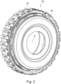
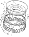
- FIG. 2 shows a perspective view of the driver unit 80 of the Figure 1 shown coupling device 10 and Figure 3 shows an exploded view of the Figure 2 shown driver unit 80. Figure 3 shows an exploded view of the Figure 2 shown driver unit 80.
- the embodiment also includes, for example, a shim 160 and a securing device 165.
- the securing device 165 includes a securing element 170, which is designed as a securing ring.
- the thrust ring 86 has a third external toothing 175 on the radially outer side.
- the third external toothing 175 has individual teeth 180.
- the teeth 180 are arranged spaced apart from one another in the circumferential direction.
- the teeth 180 are designed to correspond to the second internal toothing 155 of the first disk carrier 85.
- the teeth 180 extend outward in the radial direction.
- the thrust ring 86 comprises at least one first engagement element 185 arranged radially on the outer side in the circumferential direction between the teeth 180.
- a plurality of teeth for example two teeth 180, are arranged between the first engagement elements 185.
- the teeth 180 engage the second internal toothing 155.
- the teeth 180 and the internal toothing 155 torque-lockingly connect the thrust ring 86 to the first disk carrier 85.
- the first engagement element 185 extends radially outward and is arranged in the same rotational plane as the teeth 180 of the third external toothing 175.
- the first engagement element 185 is dovetail-shaped.
- the first engagement element 185 has a first engagement flank 190 and a second engagement flank 195.
- the first engagement flank 190 and the second engagement flank 195 are arranged opposite one another in the circumferential direction.
- the engagement flanks 190, 195 are each arranged in one plane, with the planes in which the engagement flanks 190, 195 are arranged intersecting radially inward of the first engagement element 185.
- the engagement flanks 190, 195 are arranged obliquely to one another, for example.
- the pressure ring 86 further has at least one second engagement element 205 on an end face 200, which is arranged on a side facing away from the friction pack 55, 60.
- a plurality of second engagement elements 205 are provided on the end face 200 at regular intervals in the circumferential direction.
- the second engagement elements 205 are web-shaped and extend in the axial direction parallel to the rotation axis 15.
- the first engagement element 185 and the second engagement element 205 are each arranged at approximately the same height in the circumferential direction.
- the first engagement element 185 and the second engagement element 205 to be arranged offset from one another in the circumferential direction.
- the driver part 90 is in the embodiment Disc-shaped. Radially outward, the driver part 90 has a plurality of first recesses 210, which are configured to correspond to the second engagement element 205. The arrangement of the first recess 210 is selected to correspond to the arrangement of the second engagement elements 205.
- the shim washer 160 is arranged axially between the driver part 90 and the thrust ring 86.
- the shim washer 160 is annular.
- the shim washer 160 it is also conceivable for the shim washer 160 to be partially annular or of some other design. It is also conceivable for the shim washer 160 to be omitted.
- the thickness of the shim washer 160 is selected such that the driver unit 80 is essentially free of play in the axial direction. The shim washer 160 thus achieves tolerance compensation between the thrust ring 86, the first disk carrier 85, and the driver part 90.
- the shim 160 has a plurality of second recesses 215 arranged in the circumferential direction.
- the second recesses 215 are arranged at a corresponding circumferential spacing to the arrangement of the second engagement elements 205 on the pressure ring 86.
- the configuration of the second recess 215 corresponds to the second engagement element 205.
- every second engagement element 205 extends through the first and second recesses 215, 210.
- the driver part 90 is connected to the pressure ring 86 in a torque-locking manner.
- the second engagement element 205 is caulked during assembly of the driver unit 80 after the second engagement elements 205 have been pushed through the first and second recesses 210, 215. This is advantageously carried out before inserting the pressure ring 86 into the first disk carrier 85, since the caulking forces required to caulk the second engagement element 205 can then be easily supported on a die.
- the first disk carrier 85 has a recess 220 on a side facing the driver part 90.
- the recess 220 can be introduced into the first disk carrier 85, for example, by a punching process after rolling the second internal toothing 155.
- the recess 220 is open toward the pressure ring 86.
- a fourth external toothing 225 is formed radially on the outside of the first disk carrier 85.
- the fourth external toothing 225 has external toothing teeth 230 extending radially outward.
- An external toothing root 235 is provided between the external toothing teeth 230. Adjacent to the external toothing root 235, each external toothing tooth 230 has an external toothing flank 240, 245.
- the first engagement element 185 extends radially outward through the recess 220.
- the first engagement flank 190 is aligned correspondingly to a first external tooth flank 240 of the third external toothing 230.
- the second engagement flank 195 is arranged correspondingly to a second external tooth flank 245 of the third external toothing 230.
- the first engagement flank 190 rests radially outward against the first external tooth flank 240, and the second engagement flank 195 rests radially outward against the second external tooth flank 245.
- first engagement flank 190 and the second engagement flank 195 are arranged circumferentially spaced from one another in such a way that they have an oversize in the circumferential direction relative to a distance between the first external tooth flank 240 and the second external tooth flank 245. In this way, the pressure ring 86 can be connected to the first disk carrier 85 without play.
- the securing device 165 has a groove 250 arranged on an inner circumferential surface of the first disk carrier 85, axially adjacent to the first friction pack 55.
- the securing element 170 engages in the groove 250.
- the pressure ring 86 provides the counterforce F G for pressing the friction partners 65, 70 of the first friction assembly 55 by means of a rearward support of the pressure ring 86 via the shim 160 and the driver part 90 on the securing element 170.
- the torque M is introduced into the clutch device 10 via the input side 20, the torque M is transmitted radially outward to the first recesses 210 via the driver part 90.
- the torque is transferred to the pressure ring 86 via the first recess 210 and the second engagement element 205.
- the pressure ring 86 transfers the torque to the second internal toothing 155 by means of the teeth 180.
- the torque M is transferred from the first plate carrier 85 to the second plate carrier 135, which then transmits the torque M to the second hub 35 and from the second hub 35 to the second transmission input shaft 45.
- the torque transmission takes place essentially between the teeth 180 and the internal toothing 155.
- a smaller number of first engagement elements 185 is compared to a number of teeth 180 of the third external toothing 175. This ensures that the torque is transmitted predominantly between the teeth 180 and the internal toothing 155.
- the first engagement elements 185 extend radially outward in a web-like manner, they are flexible and essentially function as a spring device that prevents rattling of the teeth 180 in the second internal toothing 155. This allows the driver unit 80 and thus also the clutch device 10 to be designed to be particularly quiet.
- the dovetail-like design of the first engagement element 185 ensures lower loading of the first plate carrier 85 and reduces radial expansion of the first plate carrier 85 caused by a centrifugal force acting on the first plate carrier 85 under the influence of rotational speed.
- the second engagement element 205 is bent radially inwards or outwards in order to ensure an axial position of the pressure ring 86 in conjunction with the shim 160 relative to the driver part 90.
- the pressure ring 86 is connected to the shim 160 and the driver part 90 by caulking and/or bending the second engagement element 205
- the pressure ring 86 with the shim 160 and the driver part 90 is inserted into the first disk carrier 85 so that the first engagement element 185 engages in the recess 220.
- the securing element 170 is inserted so that the securing element 170 engages in the groove 250, thus determining the axial position of the pressure ring 86, the shim 160, and the driver part 90.
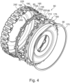
- Figure 4 shows an exploded view of a variant of the Figures 1 to 3
- the driver unit 80 is similar to the one shown in the Figures 1 to 3 shown driver unit 80.
- the third external toothing 175 is not arranged on the pressure ring 86, but radially on the outside of the driver part 90.
- no further tooth 180 of the third external toothing 175 is provided between the first engagement elements 185.
- the shim washer 160 shown in the figure is omitted.
- Figure 4 which is already in Figure 3 explained shim 160 is provided axially between the pressure ring 86 and the driver part 90.
- the driver part 90 is connected to the pressure ring 86 in a torque-locking manner via the engagement of the engagement element 205 in the first recess 210. Furthermore, the third external toothing 175, in the assembled state, engages with the second internal toothing 155 of the first disk carrier 85. The torque exchange between the first disk carrier 85 and the driver part 90 occurs predominantly via the second internal toothing 155 and the third external toothing 175.
- the first engagement element 185 engages behind the first disk carrier 85 from the radial inside. By means of the first engagement element 185, a play-free connection is achieved between the pressure ring 86 and the first disk carrier 85.
- the driver unit 80 is overall backlash-free. If the torque M is introduced into the driver part 90 via the input side 20, the torque M is predominantly transferred to the first disk carrier 85 via the teeth 180 of the third external toothing 175. If necessary, a small portion of the torque M is transferred to the thrust ring 86 via the first recess 210 and the second engagement element 205, and from the thrust ring 86 via the first engagement element 185 to the fourth external toothing 225.
- the Figure 4 The design of the driver unit 80 described has, compared to the design described in the Figures 1 to 3
- the embodiment of the driver unit 80 shown has the advantage that a higher torque M can be exchanged between the first disk carrier 85 and the driver part 90. This is due in particular to the fact that a larger number of teeth 180 of the third external toothing 175 are available for torque exchange between the second internal toothing 155 and the third external toothing 175.
- the driver unit 80 in particular the pressure ring 86 and the driver part 90, is also suitable for connection to the second, third and/or fourth disk carrier 135, 140, 145 for introducing or discharging the torque into or from the second, third and/or fourth disk carrier 135, 140, 145.
- the clutch device 10 described is designed as a double clutch in the embodiment.
- the double clutch is designed as a wet-running double clutch, so that a cooling fluid is provided to cool the friction packs 55, 60.
- the clutch device 10 it is also conceivable for the clutch device 10 to be designed as a single clutch—i.e., with only one friction pack 55, 60.
- Other configurations of the clutch device 10 are also conceivable.
Landscapes
- Engineering & Computer Science (AREA)
- General Engineering & Computer Science (AREA)
- Mechanical Engineering (AREA)
- Mechanical Operated Clutches (AREA)
- Hydraulic Clutches, Magnetic Clutches, Fluid Clutches, And Fluid Joints (AREA)
Claims (7)
- Dispositif d'embrayage (10) qui peut être disposé de façon à pouvoir pivoter autour d'un axe de rotation (15) ;- comportant un dispositif d'entraînement (80), un dispositif d'actionnement (105, 110), un côté d'entrée (20), un côté de sortie (25) et un paquet de friction (55, 60) ;- dans lequel le paquet de friction (55, 60) comporte un premier élément associé de friction (65) et un deuxième élément associé de friction (70) ;- dans lequel le dispositif d'entraînement (80) comprend un support de lamelles (85), une partie d'entraînement (90) et une bague de pression (86) ;- dans lequel le support de lamelles (85) est couplé au premier élément associé de friction (65) par complémentarité de couples de rotation ;- dans lequel le deuxième élément associé de friction (70) peut être couplé au côté de sortie (25) par complémentarité de couples de rotation ;- dans lequel le dispositif d'actionnement (105, 110) est réalisé pour mettre à disposition une force d'actionnement (F) ;- dans lequel la bague de pression (86) est en partie disposée et réalisée dans le plan axial de façon connexe au paquet de friction (55, 60) et au support de lamelles (85) pour mettre à disposition une contre-force (F G ) correspondant à la force d'actionnement F, pour les mettre en pression l'un contre l'autre à l'aide de la force d'actionnement (F) et de l'élément associé de friction (65, 70) et pour atteindre une complémentarité de frottements dans le paquet de friction (55, 60) ;- dans lequel la partie d'entraînement (90) est reliée à la bague de pression (86) par complémentarité de couple de rotation ;caractérisé en ce que le support de lamelles (85) comporte un endentement intérieur et la bague de pression (86) comporte un endentement extérieur, dans lequel l'endentement intérieur et l'endentement extérieur s'engrènent l'un dans l'autre et relient la bague de pression (86) au support de lamelles (85) par complémentarité de couple de rotation, amenant la réalisation d'une transmission de couple de rotation entre le support de lamelles (85) et la partie d'entraînement (90) via la bague de pression (86) ;- dans lequel le support de lamelles (85) comprend un endentement extérieur supplémentaire et la bague de pression (86) comprend au moins un premier élément de préhension (185) s'étendant vers l'extérieur dans le plan radial ;- dans lequel le premier élément de préhension (185) comporte un premier flanc de préhension (190) et l'endentement extérieur supplémentaire comporte au moins un flanc d'endentement extérieur (240) ;- dans lequel le premier élément de préhension (185) agrippe un évidement (220) du support de lamelles (85) en le traversant dans la direction radiale ;- dans lequel le premier flanc de préhension (190) est disposé sur le côté extérieur dans le plan radial du flanc d'endentement extérieur (240) et de façon correspondante par rapport au flanc d'endentement extérieur (240) et comporte un contact par voie tactile avec le flanc d'endentement extérieur (240) ;- dans lequel la bague de pression (86) comporte au moins un deuxième élément de préhension (205) s'étendant dans la direction axiale ;- dans lequel la partie d'entraînement (90) comporte au moins un premier évidement (210) réalisé de façon correspondante au deuxième élément de préhension (205) ;- dans lequel le deuxième élément de préhension (205) s'engrène dans le premier évidement (210) pour réaliser la liaison par complémentarité de couple de rotation de la bague de pression (86) avec la partie d'entraînement (90).
- Dispositif d'embrayage (10) selon la revendication 1,- dans lequel le premier élément de préhension (185) comporte un deuxième flanc de préhension (195) :- dans lequel le deuxième flanc de préhension (195) est disposé sur un côté opposé dans la direction périphérique par rapport au premier flanc de préhension (190) au niveau du premier élément de préhension (185) ;- dans lequel les deux flancs de préhension (190, 195) sont réalisés de façon à confluer l'un vers l'autre.
- Dispositif d'embrayage (10) selon la revendication 1,- dans lequel le dispositif d'entraînement (80) comprend une rondelle d'ajustage (160) ;- dans lequel la rondelle d'ajustage (160) est disposée dans le plan axial entre la bague de pression (86) et la partie d'entraînement (90) ;- dans lequel la rondelle d'ajustage (160) comporte au moins un deuxième évidement (215) réalisé de façon correspondante par rapport au deuxième élément de préhension (205) ;- dans lequel le deuxième élément de préhension (205) agrippe le deuxième évidement (215) en le traversant ;
- Dispositif d'embrayage (10) selon la revendication 3,- dans lequel le premier élément de préhension (185) et le deuxième élément de préhension (205) sont disposés à même hauteur dans la direction circonférentielle.
- Dispositif d'embrayage (10) selon l'une quelconque des revendications 2 à 4,- dans lequel l'endentement extérieur (175) comporte au moins une dent (180) s'étendant vers l'extérieur dans la direction radiale ;- dans lequel la dent (180) et le premier élément de préhension (185) sont disposés dans un plan de pivotement commun par rapport à l'axe de rotation (15) ;- dans lequel la dent (180) et le premier élément de préhension (185) sont disposés à une certaine distance l'un de l'autre dans la direction circonférentielle.
- Dispositif d'embrayage (10) selon la revendication 5,- dans lequel au moins deux premiers éléments de préhension (185) sont prévus ;- dans lequel la dent (180), de préférence deux dents (180), sont disposées dans la direction circonférentielle entre les deux premiers éléments de préhension (185).
- Dispositif d'embrayage (10) selon l'une quelconque des revendications 1 à 6, dans lequel le dispositif d'embrayage (10) est réalisé sous la forme d'un double embrayage, notamment d'un double embrayage fonctionnant en milieu lubrifié.
Applications Claiming Priority (1)
| Application Number | Priority Date | Filing Date | Title |
|---|---|---|---|
| DE102015203558.1A DE102015203558A1 (de) | 2015-02-27 | 2015-02-27 | Kupplungseinrichtung |
Publications (3)
| Publication Number | Publication Date |
|---|---|
| EP3061984A1 EP3061984A1 (fr) | 2016-08-31 |
| EP3061984B1 EP3061984B1 (fr) | 2019-04-10 |
| EP3061984B2 true EP3061984B2 (fr) | 2025-04-02 |
Family
ID=55404632
Family Applications (1)
| Application Number | Title | Priority Date | Filing Date |
|---|---|---|---|
| EP16156474.5A Active EP3061984B2 (fr) | 2015-02-27 | 2016-02-19 | Dispositif d'embrayage |
Country Status (2)
| Country | Link |
|---|---|
| EP (1) | EP3061984B2 (fr) |
| DE (1) | DE102015203558A1 (fr) |
Families Citing this family (5)
| Publication number | Priority date | Publication date | Assignee | Title |
|---|---|---|---|---|
| DE102015203558A1 (de) | 2015-02-27 | 2016-09-01 | Schaeffler Technologies AG & Co. KG | Kupplungseinrichtung |
| DE102015215817B4 (de) | 2015-08-19 | 2024-06-13 | Schaeffler Technologies AG & Co. KG | Mitnehmereinheit für eine Kupplungseinrichtung |
| US10570967B2 (en) * | 2016-09-07 | 2020-02-25 | Dual Clutch IP Limited | Clutch basket assembly |
| DE102017111261A1 (de) | 2017-05-23 | 2018-11-29 | Dr. Ing. H.C. F. Porsche Aktiengesellschaft | Kupplungseinrichtung und Verfahren zur Herstellung eines Druckrings für eine Kupplungseinrichtung |
| FR3133222B1 (fr) * | 2022-03-01 | 2024-03-15 | Valeo Embrayages | Module d’embrayage et procede de fermeture d’un tel module d’embrayage |
Citations (2)
| Publication number | Priority date | Publication date | Assignee | Title |
|---|---|---|---|---|
| DE102012006730A1 (de) † | 2012-04-02 | 2013-10-02 | Borgwarner Inc. | Kupplungseinrichtung |
| DE102013012815A1 (de) † | 2012-11-20 | 2014-05-22 | Borgwarner Inc. | Doppelkupplungseinrichtung und Verfahren zur Montage einer Doppelkupplungseinrichtung |
Family Cites Families (13)
| Publication number | Priority date | Publication date | Assignee | Title |
|---|---|---|---|---|
| EP1382872B1 (fr) | 2002-07-16 | 2020-06-17 | BorgWarner, Inc. | Plateau d'entraînement pour embrayage multi-disques |
| DE50301795D1 (de) | 2002-11-19 | 2006-01-05 | Volkswagen Ag | Kfz-Getriebe mit Lamellenkupplung |
| EP1645765B1 (fr) | 2004-10-06 | 2018-09-12 | BorgWarner, Inc. | Ensemble de transmission |
| DE102004057158A1 (de) * | 2004-11-26 | 2006-06-01 | Volkswagen Ag | Kfz-Getriebe |
| DE502005007187D1 (de) | 2005-06-01 | 2009-06-10 | Borgwarner Inc | Mehrfachkupplungseinrichtung |
| US7854306B2 (en) * | 2006-02-22 | 2010-12-21 | Schaeffler Technologies Gmbh & Co. Kg | Clutch assembly with an oil pump clutch housing and a carrier engaged with a clutch pack outer circumference |
| CN102200173A (zh) | 2010-03-25 | 2011-09-28 | 博格华纳公司 | 同心双离合器装置 |
| DE102012017951A1 (de) | 2011-11-10 | 2013-05-16 | Borgwarner Inc. | Betätigungselement zur Betätigung eines Lamellenpakets und parallele Doppelkupplungseinrichtung mit einem solchen Betätigungselement |
| DE102012011180B4 (de) * | 2012-06-06 | 2025-01-09 | Borgwarner Inc. | Kupplungseinrichtung |
| US20140238812A1 (en) * | 2013-02-27 | 2014-08-28 | Schaeffler Group Usa, Inc. | Drive assembly for an automatic transmission including a clutch damper |
| DE102014205064B4 (de) * | 2013-04-02 | 2025-08-14 | Schaeffler Technologies AG & Co. KG | Kupplung aufweisend einen Druckring mit Bajonettverschluss |
| DE102014014985A1 (de) | 2014-02-25 | 2015-08-27 | Borgwarner Inc. | Konzentrische Doppelkupplungseinrichtung |
| DE102015203558A1 (de) | 2015-02-27 | 2016-09-01 | Schaeffler Technologies AG & Co. KG | Kupplungseinrichtung |
-
2015
- 2015-02-27 DE DE102015203558.1A patent/DE102015203558A1/de not_active Withdrawn
-
2016
- 2016-02-19 EP EP16156474.5A patent/EP3061984B2/fr active Active
Patent Citations (2)
| Publication number | Priority date | Publication date | Assignee | Title |
|---|---|---|---|---|
| DE102012006730A1 (de) † | 2012-04-02 | 2013-10-02 | Borgwarner Inc. | Kupplungseinrichtung |
| DE102013012815A1 (de) † | 2012-11-20 | 2014-05-22 | Borgwarner Inc. | Doppelkupplungseinrichtung und Verfahren zur Montage einer Doppelkupplungseinrichtung |
Also Published As
| Publication number | Publication date |
|---|---|
| DE102015203558A1 (de) | 2016-09-01 |
| EP3061984B1 (fr) | 2019-04-10 |
| EP3061984A1 (fr) | 2016-08-31 |
Similar Documents
| Publication | Publication Date | Title |
|---|---|---|
| EP3139053B1 (fr) | Double embrayage dote d'un piston vertical et de butees d'embrayage ameliorees | |
| EP3061984B2 (fr) | Dispositif d'embrayage | |
| EP2732174B1 (fr) | Double embrayage | |
| EP2905492B1 (fr) | Système de couplage et procédé de fabrication correspondant | |
| DE102015213874A1 (de) | Axiale Lamellenkupplung | |
| DE102007031963A1 (de) | Kupplung, vzw. Doppelkupplung für ein Kraftfahrzeug | |
| DE102014205506A1 (de) | Lagerung und axiale Abstützung einer Doppelkupplung an einer Getriebeeingangswelle | |
| WO2013053432A1 (fr) | Disque de frein | |
| DE102007027120A1 (de) | Kupplung | |
| EP1726842B1 (fr) | Ensemble embrayage avec embrayages voisins dans le sens radial. | |
| EP2110574B1 (fr) | Agencement de support de disques doté d'un support de disques, embrayage à disques doté de l'agencement de support de disques et procédé de fabrication de l'agencement de support de disques | |
| WO2020169140A1 (fr) | Système d'embrayage compact à système support de disques | |
| DE112015000224T5 (de) | Automatikgetriebe | |
| EP3927991B1 (fr) | Système d'embrayage compact doté d'un corps d'appui | |
| DE102015225034A1 (de) | Lamellenträgerverbindung | |
| WO2009033937A1 (fr) | Agencement pour le soutien axial d'un disque terminal d'un groupe de disques au moyen d'une bague élastique | |
| DE102017130853B4 (de) | Kupplungseinrichtung | |
| WO2018091022A1 (fr) | Dispositif de transmission de couple | |
| EP3874174B1 (fr) | Embrayage à friction | |
| DE102011006028A1 (de) | Sicherungselement für Doppelkupplung | |
| DE102009060351A1 (de) | Kupplung | |
| WO2015124152A1 (fr) | Support pour éléments de friction d'un double embrayage | |
| DE102015224817B4 (de) | Mitnehmereinheit und Kupplungseinrichtung | |
| DE102016211988B4 (de) | Kupplungseinrichtung | |
| DE102021126010A1 (de) | Nasskupplung mit drehzahloptimiertem Innenlamellenträger |
Legal Events
| Date | Code | Title | Description |
|---|---|---|---|
| PUAI | Public reference made under article 153(3) epc to a published international application that has entered the european phase |
Free format text: ORIGINAL CODE: 0009012 |
|
| AK | Designated contracting states |
Kind code of ref document: A1 Designated state(s): AL AT BE BG CH CY CZ DE DK EE ES FI FR GB GR HR HU IE IS IT LI LT LU LV MC MK MT NL NO PL PT RO RS SE SI SK SM TR |
|
| AX | Request for extension of the european patent |
Extension state: BA ME |
|
| STAA | Information on the status of an ep patent application or granted ep patent |
Free format text: STATUS: REQUEST FOR EXAMINATION WAS MADE |
|
| 17P | Request for examination filed |
Effective date: 20170228 |
|
| RBV | Designated contracting states (corrected) |
Designated state(s): AL AT BE BG CH CY CZ DE DK EE ES FI FR GB GR HR HU IE IS IT LI LT LU LV MC MK MT NL NO PL PT RO RS SE SI SK SM TR |
|
| STAA | Information on the status of an ep patent application or granted ep patent |
Free format text: STATUS: EXAMINATION IS IN PROGRESS |
|
| 17Q | First examination report despatched |
Effective date: 20180214 |
|
| GRAP | Despatch of communication of intention to grant a patent |
Free format text: ORIGINAL CODE: EPIDOSNIGR1 |
|
| STAA | Information on the status of an ep patent application or granted ep patent |
Free format text: STATUS: GRANT OF PATENT IS INTENDED |
|
| INTG | Intention to grant announced |
Effective date: 20181031 |
|
| GRAS | Grant fee paid |
Free format text: ORIGINAL CODE: EPIDOSNIGR3 |
|
| GRAA | (expected) grant |
Free format text: ORIGINAL CODE: 0009210 |
|
| STAA | Information on the status of an ep patent application or granted ep patent |
Free format text: STATUS: THE PATENT HAS BEEN GRANTED |
|
| AK | Designated contracting states |
Kind code of ref document: B1 Designated state(s): AL AT BE BG CH CY CZ DE DK EE ES FI FR GB GR HR HU IE IS IT LI LT LU LV MC MK MT NL NO PL PT RO RS SE SI SK SM TR |
|
| REG | Reference to a national code |
Ref country code: GB Ref legal event code: FG4D Free format text: NOT ENGLISH |
|
| REG | Reference to a national code |
Ref country code: CH Ref legal event code: EP Ref country code: AT Ref legal event code: REF Ref document number: 1119080 Country of ref document: AT Kind code of ref document: T Effective date: 20190415 |
|
| REG | Reference to a national code |
Ref country code: IE Ref legal event code: FG4D Free format text: LANGUAGE OF EP DOCUMENT: GERMAN |
|
| REG | Reference to a national code |
Ref country code: DE Ref legal event code: R096 Ref document number: 502016004072 Country of ref document: DE |
|
| REG | Reference to a national code |
Ref country code: NL Ref legal event code: MP Effective date: 20190410 |
|
| REG | Reference to a national code |
Ref country code: LT Ref legal event code: MG4D |
|
| PG25 | Lapsed in a contracting state [announced via postgrant information from national office to epo] |
Ref country code: NL Free format text: LAPSE BECAUSE OF FAILURE TO SUBMIT A TRANSLATION OF THE DESCRIPTION OR TO PAY THE FEE WITHIN THE PRESCRIBED TIME-LIMIT Effective date: 20190410 |
|
| PG25 | Lapsed in a contracting state [announced via postgrant information from national office to epo] |
Ref country code: ES Free format text: LAPSE BECAUSE OF FAILURE TO SUBMIT A TRANSLATION OF THE DESCRIPTION OR TO PAY THE FEE WITHIN THE PRESCRIBED TIME-LIMIT Effective date: 20190410 Ref country code: AL Free format text: LAPSE BECAUSE OF FAILURE TO SUBMIT A TRANSLATION OF THE DESCRIPTION OR TO PAY THE FEE WITHIN THE PRESCRIBED TIME-LIMIT Effective date: 20190410 Ref country code: SE Free format text: LAPSE BECAUSE OF FAILURE TO SUBMIT A TRANSLATION OF THE DESCRIPTION OR TO PAY THE FEE WITHIN THE PRESCRIBED TIME-LIMIT Effective date: 20190410 Ref country code: PT Free format text: LAPSE BECAUSE OF FAILURE TO SUBMIT A TRANSLATION OF THE DESCRIPTION OR TO PAY THE FEE WITHIN THE PRESCRIBED TIME-LIMIT Effective date: 20190910 Ref country code: HR Free format text: LAPSE BECAUSE OF FAILURE TO SUBMIT A TRANSLATION OF THE DESCRIPTION OR TO PAY THE FEE WITHIN THE PRESCRIBED TIME-LIMIT Effective date: 20190410 Ref country code: FI Free format text: LAPSE BECAUSE OF FAILURE TO SUBMIT A TRANSLATION OF THE DESCRIPTION OR TO PAY THE FEE WITHIN THE PRESCRIBED TIME-LIMIT Effective date: 20190410 Ref country code: NO Free format text: LAPSE BECAUSE OF FAILURE TO SUBMIT A TRANSLATION OF THE DESCRIPTION OR TO PAY THE FEE WITHIN THE PRESCRIBED TIME-LIMIT Effective date: 20190710 Ref country code: LT Free format text: LAPSE BECAUSE OF FAILURE TO SUBMIT A TRANSLATION OF THE DESCRIPTION OR TO PAY THE FEE WITHIN THE PRESCRIBED TIME-LIMIT Effective date: 20190410 |
|
| PG25 | Lapsed in a contracting state [announced via postgrant information from national office to epo] |
Ref country code: PL Free format text: LAPSE BECAUSE OF FAILURE TO SUBMIT A TRANSLATION OF THE DESCRIPTION OR TO PAY THE FEE WITHIN THE PRESCRIBED TIME-LIMIT Effective date: 20190410 Ref country code: RS Free format text: LAPSE BECAUSE OF FAILURE TO SUBMIT A TRANSLATION OF THE DESCRIPTION OR TO PAY THE FEE WITHIN THE PRESCRIBED TIME-LIMIT Effective date: 20190410 Ref country code: GR Free format text: LAPSE BECAUSE OF FAILURE TO SUBMIT A TRANSLATION OF THE DESCRIPTION OR TO PAY THE FEE WITHIN THE PRESCRIBED TIME-LIMIT Effective date: 20190711 Ref country code: BG Free format text: LAPSE BECAUSE OF FAILURE TO SUBMIT A TRANSLATION OF THE DESCRIPTION OR TO PAY THE FEE WITHIN THE PRESCRIBED TIME-LIMIT Effective date: 20190710 Ref country code: LV Free format text: LAPSE BECAUSE OF FAILURE TO SUBMIT A TRANSLATION OF THE DESCRIPTION OR TO PAY THE FEE WITHIN THE PRESCRIBED TIME-LIMIT Effective date: 20190410 |
|
| PG25 | Lapsed in a contracting state [announced via postgrant information from national office to epo] |
Ref country code: IS Free format text: LAPSE BECAUSE OF FAILURE TO SUBMIT A TRANSLATION OF THE DESCRIPTION OR TO PAY THE FEE WITHIN THE PRESCRIBED TIME-LIMIT Effective date: 20190810 |
|
| REG | Reference to a national code |
Ref country code: DE Ref legal event code: R026 Ref document number: 502016004072 Country of ref document: DE |
|
| PLBI | Opposition filed |
Free format text: ORIGINAL CODE: 0009260 |
|
| PLAX | Notice of opposition and request to file observation + time limit sent |
Free format text: ORIGINAL CODE: EPIDOSNOBS2 |
|
| PG25 | Lapsed in a contracting state [announced via postgrant information from national office to epo] |
Ref country code: DK Free format text: LAPSE BECAUSE OF FAILURE TO SUBMIT A TRANSLATION OF THE DESCRIPTION OR TO PAY THE FEE WITHIN THE PRESCRIBED TIME-LIMIT Effective date: 20190410 Ref country code: SK Free format text: LAPSE BECAUSE OF FAILURE TO SUBMIT A TRANSLATION OF THE DESCRIPTION OR TO PAY THE FEE WITHIN THE PRESCRIBED TIME-LIMIT Effective date: 20190410 Ref country code: EE Free format text: LAPSE BECAUSE OF FAILURE TO SUBMIT A TRANSLATION OF THE DESCRIPTION OR TO PAY THE FEE WITHIN THE PRESCRIBED TIME-LIMIT Effective date: 20190410 Ref country code: CZ Free format text: LAPSE BECAUSE OF FAILURE TO SUBMIT A TRANSLATION OF THE DESCRIPTION OR TO PAY THE FEE WITHIN THE PRESCRIBED TIME-LIMIT Effective date: 20190410 Ref country code: RO Free format text: LAPSE BECAUSE OF FAILURE TO SUBMIT A TRANSLATION OF THE DESCRIPTION OR TO PAY THE FEE WITHIN THE PRESCRIBED TIME-LIMIT Effective date: 20190410 |
|
| 26 | Opposition filed |
Opponent name: BORGWARNER INC. Effective date: 20200107 |
|
| PG25 | Lapsed in a contracting state [announced via postgrant information from national office to epo] |
Ref country code: IT Free format text: LAPSE BECAUSE OF FAILURE TO SUBMIT A TRANSLATION OF THE DESCRIPTION OR TO PAY THE FEE WITHIN THE PRESCRIBED TIME-LIMIT Effective date: 20190410 Ref country code: SM Free format text: LAPSE BECAUSE OF FAILURE TO SUBMIT A TRANSLATION OF THE DESCRIPTION OR TO PAY THE FEE WITHIN THE PRESCRIBED TIME-LIMIT Effective date: 20190410 |
|
| PG25 | Lapsed in a contracting state [announced via postgrant information from national office to epo] |
Ref country code: TR Free format text: LAPSE BECAUSE OF FAILURE TO SUBMIT A TRANSLATION OF THE DESCRIPTION OR TO PAY THE FEE WITHIN THE PRESCRIBED TIME-LIMIT Effective date: 20190410 |
|
| PG25 | Lapsed in a contracting state [announced via postgrant information from national office to epo] |
Ref country code: SI Free format text: LAPSE BECAUSE OF FAILURE TO SUBMIT A TRANSLATION OF THE DESCRIPTION OR TO PAY THE FEE WITHIN THE PRESCRIBED TIME-LIMIT Effective date: 20190410 |
|
| PLBB | Reply of patent proprietor to notice(s) of opposition received |
Free format text: ORIGINAL CODE: EPIDOSNOBS3 |
|
| REG | Reference to a national code |
Ref country code: CH Ref legal event code: PL |
|
| GBPC | Gb: european patent ceased through non-payment of renewal fee |
Effective date: 20200219 |
|
| REG | Reference to a national code |
Ref country code: BE Ref legal event code: MM Effective date: 20200229 |
|
| PG25 | Lapsed in a contracting state [announced via postgrant information from national office to epo] |
Ref country code: MC Free format text: LAPSE BECAUSE OF FAILURE TO SUBMIT A TRANSLATION OF THE DESCRIPTION OR TO PAY THE FEE WITHIN THE PRESCRIBED TIME-LIMIT Effective date: 20190410 Ref country code: LU Free format text: LAPSE BECAUSE OF NON-PAYMENT OF DUE FEES Effective date: 20200219 |
|
| PG25 | Lapsed in a contracting state [announced via postgrant information from national office to epo] |
Ref country code: CH Free format text: LAPSE BECAUSE OF NON-PAYMENT OF DUE FEES Effective date: 20200229 Ref country code: LI Free format text: LAPSE BECAUSE OF NON-PAYMENT OF DUE FEES Effective date: 20200229 |
|
| PG25 | Lapsed in a contracting state [announced via postgrant information from national office to epo] |
Ref country code: GB Free format text: LAPSE BECAUSE OF NON-PAYMENT OF DUE FEES Effective date: 20200219 Ref country code: IE Free format text: LAPSE BECAUSE OF NON-PAYMENT OF DUE FEES Effective date: 20200219 |
|
| PG25 | Lapsed in a contracting state [announced via postgrant information from national office to epo] |
Ref country code: BE Free format text: LAPSE BECAUSE OF NON-PAYMENT OF DUE FEES Effective date: 20200229 |
|
| REG | Reference to a national code |
Ref country code: AT Ref legal event code: MM01 Ref document number: 1119080 Country of ref document: AT Kind code of ref document: T Effective date: 20210219 |
|
| PG25 | Lapsed in a contracting state [announced via postgrant information from national office to epo] |
Ref country code: AT Free format text: LAPSE BECAUSE OF NON-PAYMENT OF DUE FEES Effective date: 20210219 |
|
| PG25 | Lapsed in a contracting state [announced via postgrant information from national office to epo] |
Ref country code: MT Free format text: LAPSE BECAUSE OF FAILURE TO SUBMIT A TRANSLATION OF THE DESCRIPTION OR TO PAY THE FEE WITHIN THE PRESCRIBED TIME-LIMIT Effective date: 20190410 Ref country code: CY Free format text: LAPSE BECAUSE OF FAILURE TO SUBMIT A TRANSLATION OF THE DESCRIPTION OR TO PAY THE FEE WITHIN THE PRESCRIBED TIME-LIMIT Effective date: 20190410 |
|
| PG25 | Lapsed in a contracting state [announced via postgrant information from national office to epo] |
Ref country code: MK Free format text: LAPSE BECAUSE OF FAILURE TO SUBMIT A TRANSLATION OF THE DESCRIPTION OR TO PAY THE FEE WITHIN THE PRESCRIBED TIME-LIMIT Effective date: 20190410 |
|
| APBM | Appeal reference recorded |
Free format text: ORIGINAL CODE: EPIDOSNREFNO |
|
| APBP | Date of receipt of notice of appeal recorded |
Free format text: ORIGINAL CODE: EPIDOSNNOA2O |
|
| APAH | Appeal reference modified |
Free format text: ORIGINAL CODE: EPIDOSCREFNO |
|
| APAW | Appeal reference deleted |
Free format text: ORIGINAL CODE: EPIDOSDREFNO |
|
| APBM | Appeal reference recorded |
Free format text: ORIGINAL CODE: EPIDOSNREFNO |
|
| APBP | Date of receipt of notice of appeal recorded |
Free format text: ORIGINAL CODE: EPIDOSNNOA2O |
|
| APBQ | Date of receipt of statement of grounds of appeal recorded |
Free format text: ORIGINAL CODE: EPIDOSNNOA3O |
|
| APBQ | Date of receipt of statement of grounds of appeal recorded |
Free format text: ORIGINAL CODE: EPIDOSNNOA3O |
|
| APBU | Appeal procedure closed |
Free format text: ORIGINAL CODE: EPIDOSNNOA9O |
|
| RAP4 | Party data changed (patent owner data changed or rights of a patent transferred) |
Owner name: SCHAEFFLER TECHNOLOGIES AG & CO. KG |
|
| PUAH | Patent maintained in amended form |
Free format text: ORIGINAL CODE: 0009272 |
|
| STAA | Information on the status of an ep patent application or granted ep patent |
Free format text: STATUS: PATENT MAINTAINED AS AMENDED |
|
| 27A | Patent maintained in amended form |
Effective date: 20250402 |
|
| AK | Designated contracting states |
Kind code of ref document: B2 Designated state(s): AL AT BE BG CH CY CZ DE DK EE ES FI FR GB GR HR HU IE IS IT LI LT LU LV MC MK MT NL NO PL PT RO RS SE SI SK SM TR |
|
| REG | Reference to a national code |
Ref country code: DE Ref legal event code: R102 Ref document number: 502016004072 Country of ref document: DE |
|
| PGFP | Annual fee paid to national office [announced via postgrant information from national office to epo] |
Ref country code: DE Payment date: 20260228 Year of fee payment: 11 |
|
| PGFP | Annual fee paid to national office [announced via postgrant information from national office to epo] |
Ref country code: FR Payment date: 20260218 Year of fee payment: 11 |