EP3062002B1 - Partie supérieure de soupape - Google Patents
Partie supérieure de soupape Download PDFInfo
- Publication number
- EP3062002B1 EP3062002B1 EP15156614.8A EP15156614A EP3062002B1 EP 3062002 B1 EP3062002 B1 EP 3062002B1 EP 15156614 A EP15156614 A EP 15156614A EP 3062002 B1 EP3062002 B1 EP 3062002B1
- Authority
- EP
- European Patent Office
- Prior art keywords
- disk
- duct
- valve top
- control disk
- valve
- Prior art date
- Legal status (The legal status is an assumption and is not a legal conclusion. Google has not performed a legal analysis and makes no representation as to the accuracy of the status listed.)
- Active
Links
Images


Classifications
-
- F—MECHANICAL ENGINEERING; LIGHTING; HEATING; WEAPONS; BLASTING
- F16—ENGINEERING ELEMENTS AND UNITS; GENERAL MEASURES FOR PRODUCING AND MAINTAINING EFFECTIVE FUNCTIONING OF MACHINES OR INSTALLATIONS; THERMAL INSULATION IN GENERAL
- F16K—VALVES; TAPS; COCKS; ACTUATING-FLOATS; DEVICES FOR VENTING OR AERATING
- F16K11/00—Multiple-way valves, e.g. mixing valves; Pipe fittings incorporating such valves
- F16K11/02—Multiple-way valves, e.g. mixing valves; Pipe fittings incorporating such valves with all movable sealing faces moving as one unit
- F16K11/06—Multiple-way valves, e.g. mixing valves; Pipe fittings incorporating such valves with all movable sealing faces moving as one unit comprising only sliding valves, i.e. sliding closure elements
- F16K11/072—Multiple-way valves, e.g. mixing valves; Pipe fittings incorporating such valves with all movable sealing faces moving as one unit comprising only sliding valves, i.e. sliding closure elements with pivoted closure members
- F16K11/074—Multiple-way valves, e.g. mixing valves; Pipe fittings incorporating such valves with all movable sealing faces moving as one unit comprising only sliding valves, i.e. sliding closure elements with pivoted closure members with flat sealing faces
- F16K11/0746—Multiple-way valves, e.g. mixing valves; Pipe fittings incorporating such valves with all movable sealing faces moving as one unit comprising only sliding valves, i.e. sliding closure elements with pivoted closure members with flat sealing faces with two or more closure plates comprising a single lever control
-
- F—MECHANICAL ENGINEERING; LIGHTING; HEATING; WEAPONS; BLASTING
- F16—ENGINEERING ELEMENTS AND UNITS; GENERAL MEASURES FOR PRODUCING AND MAINTAINING EFFECTIVE FUNCTIONING OF MACHINES OR INSTALLATIONS; THERMAL INSULATION IN GENERAL
- F16K—VALVES; TAPS; COCKS; ACTUATING-FLOATS; DEVICES FOR VENTING OR AERATING
- F16K27/00—Construction of housing; Use of materials therefor
- F16K27/08—Guiding yokes for spindles; Means for closing housings; Dust caps, e.g. for tyre valves
-
- F—MECHANICAL ENGINEERING; LIGHTING; HEATING; WEAPONS; BLASTING
- F16—ENGINEERING ELEMENTS AND UNITS; GENERAL MEASURES FOR PRODUCING AND MAINTAINING EFFECTIVE FUNCTIONING OF MACHINES OR INSTALLATIONS; THERMAL INSULATION IN GENERAL
- F16K—VALVES; TAPS; COCKS; ACTUATING-FLOATS; DEVICES FOR VENTING OR AERATING
- F16K11/00—Multiple-way valves, e.g. mixing valves; Pipe fittings incorporating such valves
- F16K11/02—Multiple-way valves, e.g. mixing valves; Pipe fittings incorporating such valves with all movable sealing faces moving as one unit
- F16K11/06—Multiple-way valves, e.g. mixing valves; Pipe fittings incorporating such valves with all movable sealing faces moving as one unit comprising only sliding valves, i.e. sliding closure elements
- F16K11/072—Multiple-way valves, e.g. mixing valves; Pipe fittings incorporating such valves with all movable sealing faces moving as one unit comprising only sliding valves, i.e. sliding closure elements with pivoted closure members
- F16K11/074—Multiple-way valves, e.g. mixing valves; Pipe fittings incorporating such valves with all movable sealing faces moving as one unit comprising only sliding valves, i.e. sliding closure elements with pivoted closure members with flat sealing faces
- F16K11/0743—Multiple-way valves, e.g. mixing valves; Pipe fittings incorporating such valves with all movable sealing faces moving as one unit comprising only sliding valves, i.e. sliding closure elements with pivoted closure members with flat sealing faces with both the supply and the discharge passages being on one side of the closure plates
-
- F—MECHANICAL ENGINEERING; LIGHTING; HEATING; WEAPONS; BLASTING
- F16—ENGINEERING ELEMENTS AND UNITS; GENERAL MEASURES FOR PRODUCING AND MAINTAINING EFFECTIVE FUNCTIONING OF MACHINES OR INSTALLATIONS; THERMAL INSULATION IN GENERAL
- F16K—VALVES; TAPS; COCKS; ACTUATING-FLOATS; DEVICES FOR VENTING OR AERATING
- F16K27/00—Construction of housing; Use of materials therefor
- F16K27/04—Construction of housing; Use of materials therefor of sliding valves
- F16K27/044—Construction of housing; Use of materials therefor of sliding valves slide valves with flat obturating members
- F16K27/045—Construction of housing; Use of materials therefor of sliding valves slide valves with flat obturating members with pivotal obturating members
-
- F—MECHANICAL ENGINEERING; LIGHTING; HEATING; WEAPONS; BLASTING
- F16—ENGINEERING ELEMENTS AND UNITS; GENERAL MEASURES FOR PRODUCING AND MAINTAINING EFFECTIVE FUNCTIONING OF MACHINES OR INSTALLATIONS; THERMAL INSULATION IN GENERAL
- F16K—VALVES; TAPS; COCKS; ACTUATING-FLOATS; DEVICES FOR VENTING OR AERATING
- F16K3/00—Gate valves or sliding valves, i.e. cut-off apparatus with closing members having a sliding movement along the seat for opening and closing
- F16K3/30—Details
- F16K3/314—Forms or constructions of slides; Attachment of the slide to the spindle
Definitions
- valve bonnets for sanitary fittings with the features of the preamble of claim 1.
- valve bonnets are often used, in which a control disc and a transmission disc having disc control is arranged, which is operated via a spindle such that the water outlet via a rotation of the spindle is controllable.
- Such exchangeable valve tops as used for example in the DE 20 2005 003 127 U1 can be used in differently shaped valve bodies.
- the water to be taken from a fitting is previously supplied to a filter module to improve its quality.
- the filter module is regularly upstream of the valve shell, which is why the filter module is continuously subjected to water pressure. As a result, the durability of the filter module is impaired.
- WO00 / 23168 discloses a valve bonnet according to the preamble of claim 1.
- the invention seeks to remedy this.
- the invention has for its object to provide a valve top that allows the interposition of a filter module. According to the invention, this object is solved by the features of the characterizing part of patent claim 1. With the invention, a valve top is created, which allows the interposition of a filter module.
- a recess is introduced, via which a first inlet channel for the water line inlet and the first outlet channel, which is used as an inlet for the filter module, in a rotational position of the control disk relative to the passage plate is connectable by closing the first Inlet channel by twisting the control disc relative to the passage disc simultaneously prevented the water inlet into the filter module.
- the second outlet channel is formed by at least one lateral window inserted in the head piece, wherein a passage channel is introduced in the control disk, via which the second inlet channel (filter water inlet) with the lateral window of the head piece in a rotational position of the control disk is connectable.
- the second inlet channel filter water inlet
- the second inlet channel which can be connected to the outlet of a filter module, can be closed via the control disk, thereby preventing unwanted leakage of water from the second outlet channel or from the fitting.
- the second outlet channel is formed by at least one introduced in the head piece side window, wherein in the control disk (5), a passage channel is introduced, via which the second inlet channel with the side window of the head piece in a rotational position of the control disk is connectable ,
- a passage channel is introduced, via which the second inlet channel with the side window of the head piece in a rotational position of the control disk is connectable ,
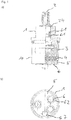
- the valve upper part chosen as an embodiment consists essentially of a head piece 1, which is penetrated centrally by a spindle 2 guided radially in it. With the spindle 2, a control disk 3 is positively connected and guided radially in the head piece 1. On the side facing away from the spindle 2 of the control disk 3, a passage disk 4 is rotatably arranged in the head piece 1, to which a bottom piece 5 is connected. The bottom piece 5 is provided with lip seals 6, via which the bottom piece 5 is sealed against the passage disk 4 and against the valve seat 7. The bottom piece 5 thus "floats" axially between the valve seat 7 and the passage disk 4.
- the head piece 1 consists of a symmetrical hollow body whose two end faces are open.
- the head piece 1 is manufactured as a brass turned part.
- the head piece 1 On its side facing the bottom piece 5, the head piece 1 has a sleeve-like part 10 in which two passage windows 11 are arranged opposite one another.
- a circumferential locking groove 17 is arranged for receiving a formed on the bottom piece 5 locking lug in the sleeve-like part inside.
- two rectangular recesses 18 for receiving the lugs 46, 55 of the passage disk 4 and the bottom piece 5 are diametrically opposed to each other at the end.
- the head piece 1 At its end opposite the passage windows 11, the head piece 1 has a reduced-diameter portion 12, in which a circumferential groove 13 is formed inside.
- the circumferential groove 13 delimiting this is formed upstream of a three-quarter circular web 14, are formed by the two radial stops 15.
- the stops 15 are used to limit the rotation of the spindle 2.
- a shoulder 16 is formed by the reduced diameter portion.
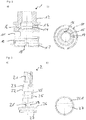
- the spindle 2 is essentially solid. It is on the side facing away from the head piece 1 end outside as external polygon 21 executed. Subsequently, a cylindrical surface 22 is provided on the outside of the spindle 32, with which the spindle 2 is guided radially in the head piece 1. Between the cylindrical surface 22 and the outer polygon 21, a recess 23 is provided, in which a shaft lock 24 is resiliently inserted in the form of a snap ring. The shaft lock 24 prevents the penetration of the spindle 2 in the head piece 1 beyond the intended extent. Furthermore, in the cylindrical surface 22, two annular grooves 25 are introduced, the O-rings 61 record.
- a disc 26 On the outer polygon 21 opposite side of the spindle 2, a disc 26 is formed, which has a driver 27 on its outer polygon 21 opposite side.
- the driver 27 enclosing a diameter-reduced shoulder 261 low height is formed on the disc 26.
- the spindle Between the cylindrical surface 22 and the disc 26, the spindle has a circular segment-shaped portion 28, the straight edges 29 include an angle of 45 degrees.
- the flanks 28 cooperate with the stops 15 formed by the three-quarter-circular web 14 in such a way that the angle of rotation of the spindle 2 is limited to 45 degrees.
- the control disk 3 is substantially formed as a circular ceramic disk, in the distance to its outer edge a connecting channel 31 is introduced in the form of a circular arc-shaped recess which extends over an angle of 90 degrees.
- the passage channel 31 opposite a circular segment-shaped cutout 32 is introduced into the control disk, which extends in the axial direction approximately over half of the lateral surface 33 of the control disk 3.
- On its spindle 2 side facing the control disk 3 has a cuboidal engagement 34 for receiving the driver 27 of the spindle 2.
- the cuboidal engagement 34 is bordered by a cylindrical depression 35 of shallow depth, the inner diameter of which substantially corresponds to the outer diameter of the shoulder 26 of the disc 26 of the spindle 2 received by this engagement 32.
- the passage disk 4 is formed substantially as compared to the control disk much thinner circular ceramic disk, in the spaced from each other three holes 41, 42, 43 are introduced.
- a channel-shaped recess 44 of small depth is introduced into the transmission disk 4, which connects a central region surrounding the center of the transmission disk 4 to the lateral surface 45 on two opposite sides, which breaks through the recess (cf. Fig. 5 a) ).
- two rectangular lugs 46 are integrally formed on the side diametrically opposite each other for engagement in the recesses 18 of the head piece 1.
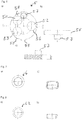
- the bottom piece 5 is formed essentially in the form of a circular disk.
- a first inlet channel 51 and a second inlet channel 52 and a first outlet channel 53 are introduced in each case in the form of a bore, whose central axes define an isosceles triangle.
- On both sides of the channels 51, 52, 53 are these enclosing in the bottom piece 5 each annular depressions 56 for receiving a respective lip seal 6 is introduced.
- the lip seals 6 each receive a support ring 62 and seal the bottom piece against the passage disk 4 and against the valve seat 7 of a valve.
- two rectangular tabs 55 are integrally formed on the bottom piece 5 to engage in the recesses 18 of the head piece 1.
- locking lugs 58 are further formed for engagement in the locking groove 17 of the head piece 1. These locking lugs 58 allow a latching connection between the bottom piece 5 and the head piece 1.At its bottom side facing away from the head piece 1 is further formed on the bottom piece 5, a positioning pin 57 for engagement with a corresponding positioning hole 75 of the valve seat 7 of a valve.
- FIG. 10 exemplified the valve seat 7 of a valve for receiving the valve upper part described above.
- the valve seat 7 is formed substantially hollow cylindrical. At its upper end is an internal thread 70 for screwing a - not shown - fixing ring arranged for fixing a valve top.
- a tap water inlet port 71, a Filtermodulzulaufan gleich 72 and a Filtermodulauslaufan gleich 73 whose central axes define an isosceles triangle.
- a trained as a blind hole positioning hole 75 is introduced for receiving the positioning pin 57 of the bottom piece 5 of the valve top.
- the side opens into the valve seat 7, a discharge line 76 which is disposed approximately at the level of the passage window 11 of the head piece 1 of a recorded valve shell.
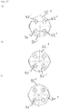
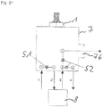
- FIG. 11 the different closing positions are shown schematically.
- the tap water (arrow 1) passes through the first blocking point S1 in the filter module 8 (arrow 2) and from here (arrow 3) via the second blocking point S2 in the outlet line 76 of the valve.
- FIG. 14 is an alternative embodiment of the control disk 3 'for the valve top after FIG. 12 shown.
- this control disk 3 " instead of the circular segment-like cutout 32 ', a second connecting channel 31" is arranged diametrically opposite the first connecting channel 31 ".
- the transmission disk 4 ' is substantially corresponding to the transmission disk 4 of the embodiment according to FIG. 1 formed, but here an additional fourth hole 47 'is introduced.
- the four holes 41 ', 42', 43 ', 47' are arranged such that their centers define a square.
- the depression 44 'in the case of this passage disk 4' is of circular design and is positioned centrally on its side of the transmission disk 4 'facing the control disk 3' (cf. FIG. 15 ).
- the bottom piece 5 ' is also substantially according to the bottom piece 5 of the valve top part FIG. 1 formed, according to the design of the passage disk 4 'also an additional bore in the form of a second outlet channel 54' is introduced.
- the two inlet channels 51 ', 52' and the two outlet channels 53 ', 54' are arranged such that they are aligned with the four holes 41 ', 42', 43 ', 47' of the passage disk 4 '.
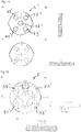
- valve seats of a fitting for receiving the valve top are after FIG. 12 shown. While the valve seat to FIG. 19 essentially following the previously described valve seat FIG. 10 for receiving the valve top part FIG. 1 corresponds, is at the valve seat to FIG. 20 instead of the lateral outlet line 76, an additional tap water outlet connection 74 is arranged on the bottom side.
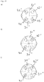
- FIG. 21 the different closing positions are shown schematically.
- the tap water (arrow 1) passes through the first blocking point S1 in the filter module 8 (arrow 2) and from here (arrow 3) via the second blocking point S2 either via a passage window 11 in the outlet line 76 of the valve seat 7 of the valve (dashed arrow ) or directly into the bottom-side tap water outlet connection 74 (arrow 4).
- the control disk 3 "according to FIG. 14 only permits the water outlet via the tap water outlet connection 74.
- FIG. 17 are different positions of the control disc 3 'in the embodiment according to FIG. 13 and the non-rotatably arranged passage disc 4 'formed disc control of the valve upper part according to FIG. 12 shown schematically.
- FIG. 18 are different positions of the control disc 3 "in the embodiment according to FIG. 14 and the non-rotatably arranged passage disc 4 'formed disc control of the valve upper part according to FIG. 12 shown schematically.
- the positions according to FIGS. 18 a) to c) correspond to the positions according to the FIGS. 17 a) to c) , where in FIG.
Landscapes
- Engineering & Computer Science (AREA)
- General Engineering & Computer Science (AREA)
- Mechanical Engineering (AREA)
- Multiple-Way Valves (AREA)
- Domestic Plumbing Installations (AREA)
- Valve Housings (AREA)
Claims (12)
- Partie supérieure de soupape pour robinetteries sanitaires, comprenant une pièce têtière recevant une pièce de fond qui présente deux canaux d'admission et au moins un premier canal de sortie, ainsi qu'une commande composée d'un disque de commande pouvant tourner, via une broche en appui rotatif, relativement à un disque de passage disposé sans pouvoir tourner, sachant qu'est disposé un deuxième canal de sortie pour le prélèvement d'eau, sachant que dans le disque de commande (3) a été ménagé un canal de liaison (31) via lequel il est possible de relier un premier canal d'admission (51) et le premier canal de sortie (53) lorsque le disque de commande (3) se trouve en position tournée par rapport au disque de passage (4), caractérisée en ce que le disque de passage (4) présente, sur son côté regardant le disque de commande (3), un creux (44) qui relie sur au moins un côté une zone médiane - entourant le milieu du disque de passage (4) - avec la surface enveloppante (45).
- Partie supérieure de soupape selon la revendication 1, caractérisée en ce que le canal de liaison (31) est configuré en arc de cercle.
- Partie supérieure de soupape selon la revendication 1 ou 2, caractérisée en ce que le deuxième canal de sortie est formé par au moins une fenêtre (11) latérale ménagée dans la pièce têtière (1), sachant que dans le disque de commande (3) a été ménagé une découpe (32) via laquelle le deuxième canal d'admission (52) peut être relié avec la fenêtre latérale (11) de la pièce têtière (1) lorsque le disque de commande (3) se trouve dans une position tournée.
- Partie supérieure de soupape selon la revendication 1 ou 2, caractérisée en ce que le deuxième canal de sortie (54) est disposé en plus du premier canal de sortie (53) dans la pièce de fond (5), sachant que dans le disque de commande sont ménagés deux canaux de liaison (31) via lesquels le premier canal d'admission (51) et le premier canal de sortie (53) sont reliables lorsque le disque de commande (3) se trouve en position tournée relativement au disque de passage (4) et via lesquels le deuxième canal d'admission (52) et le deuxième canal de sortie (54) sont reliables lorsque le disque de commande (3) se trouve en position tournée relativement au disque de passage (4).
- Partie supérieure de soupape selon la revendication 3 ou 4, caractérisée en ce que le canal de liaison (31) et la découpe (32) ou les deux canaux de liaison (31) sont disposés dans le disque de commande (3) de sorte que lorsque le disque de commande (3) se trouve en position tournée relativement au disque de passage (4), le premier canal d'admission (51) est fermé tandis que le deuxième canal de sortie (54) est au moins partiellement relié avec le deuxième canal d'admission (52), sachant que dans une autre position tournée aussi bien le premier canal d'admission (51) que le deuxième canal d'admission (52) sont fermés.
- Partie supérieure de soupape selon l'une des revendications précédentes, caractérisée en ce que le creux (44) est configuré de sorte à traverser la surface enveloppante (45) du disque de passage (4) à deux endroits distants l'un de l'autre, sachant qu'il est guidé à travers la zone médiane du disque de passage (4).
- Partie supérieure de soupape selon la revendication 6, caractérisée en ce que les deux endroits de la surface enveloppante (45) distants l'un de l'autre sont agencés l'un en face de l'autre.
- Partie supérieure de soupape selon l'une des revendications précédentes, caractérisée en ce que la pièce têtière (1) est fabriquée en métal, de préférence en laiton.
- Partie supérieure de soupape selon l'une des revendications précédentes, caractérisée en ce qu'à l'intérieur de la pièce têtière (1) sont disposées deux butées (15) qui limitent la rotation de la broche (2) à un angle de rotation.
- Partie supérieure de soupape selon la revendication 9, caractérisée en ce que la broche (2) présente un segment (28) en forme de secteur circulaire qui présente deux flancs droits (29) inclinés selon un angle l'un par rapport à l'autre, flancs qui peuvent venir heurter une butée (15) respective de la pièce têtière (1), faisant que l'angle de rotation de la broche (2) est limité.
- Partie supérieure de soupape selon la revendication 10, caractérisée en ce que les flancs (29) incluent un angle de 45 degrés et interagissent avec les butées (15) de la pièce têtière de sorte que l'angle de rotation maximum de la broche (2) est limité à 45 degrés.
- Robinetterie sanitaire avec un siège de soupape recevant une partie supérieure de soupape selon l'une des revendications précédentes, sachant que le siège de soupape (7) présente un raccord (71) d'arrivée d'eau courante, ainsi qu'un raccord (72) d'arrivée pour module filtrant et un raccord (73) de sortie pour module filtrant, sachant que le raccord (71) d'arrivée d'eau courante est relié avec le premier canal d'admission (51), le raccord (72) d'arrivée pour module filtrant est relié avec le premier canal de sortie (53) et le raccord (73) de sortie pour module filtrant est relié avec le deuxième canal d'admission (52) de la pièce de fond (5) de la partie supérieure de soupape.
Priority Applications (7)
| Application Number | Priority Date | Filing Date | Title |
|---|---|---|---|
| EP15156614.8A EP3062002B1 (fr) | 2015-02-25 | 2015-02-25 | Partie supérieure de soupape |
| ES15156614.8T ES2674383T3 (es) | 2015-02-25 | 2015-02-25 | Parte superior de válvula |
| TR2018/08927T TR201808927T4 (tr) | 2015-02-25 | 2015-02-25 | Valf üst parçası. |
| HUE15156614A HUE039264T2 (hu) | 2015-02-25 | 2015-02-25 | Szelep-felsõrész |
| TW104142600A TWI668385B (zh) | 2015-02-25 | 2015-12-18 | Upper valve |
| JP2016032286A JP6689097B2 (ja) | 2015-02-25 | 2016-02-23 | 弁上側部分 |
| CN201610100071.8A CN105909852B (zh) | 2015-02-25 | 2016-02-24 | 阀帽 |
Applications Claiming Priority (1)
| Application Number | Priority Date | Filing Date | Title |
|---|---|---|---|
| EP15156614.8A EP3062002B1 (fr) | 2015-02-25 | 2015-02-25 | Partie supérieure de soupape |
Publications (2)
| Publication Number | Publication Date |
|---|---|
| EP3062002A1 EP3062002A1 (fr) | 2016-08-31 |
| EP3062002B1 true EP3062002B1 (fr) | 2018-04-04 |
Family
ID=52574083
Family Applications (1)
| Application Number | Title | Priority Date | Filing Date |
|---|---|---|---|
| EP15156614.8A Active EP3062002B1 (fr) | 2015-02-25 | 2015-02-25 | Partie supérieure de soupape |
Country Status (7)
| Country | Link |
|---|---|
| EP (1) | EP3062002B1 (fr) |
| JP (1) | JP6689097B2 (fr) |
| CN (1) | CN105909852B (fr) |
| ES (1) | ES2674383T3 (fr) |
| HU (1) | HUE039264T2 (fr) |
| TR (1) | TR201808927T4 (fr) |
| TW (1) | TWI668385B (fr) |
Families Citing this family (7)
| Publication number | Priority date | Publication date | Assignee | Title |
|---|---|---|---|---|
| CN107651780B (zh) * | 2017-11-11 | 2021-08-17 | 孙建磊 | 一种带有洗手液的过滤塞 |
| CN112483671A (zh) * | 2020-12-10 | 2021-03-12 | 开平市凯赛德水暖配件有限公司 | 一种定位阀芯 |
| DE202023101160U1 (de) | 2023-03-10 | 2023-04-28 | Flühs Drehtechnik GmbH | Ventiloberteil für Sanitärarmaturen |
| EP4428406B1 (fr) | 2023-03-10 | 2025-05-07 | Flühs Drehtechnik GmbH | Partie supérieure de soupape pour robinetteries sanitaires |
| EP4428414B1 (fr) | 2023-03-10 | 2025-10-15 | Flühs Drehtechnik GmbH | Partie supérieure de soupape pour robinetteries sanitaires |
| DE202023101163U1 (de) | 2023-03-10 | 2023-05-08 | Flühs Drehtechnik GmbH | Ventiloberteil für Sanitärarmaturen |
| EP4585838B1 (fr) | 2024-01-10 | 2026-02-11 | Flühs Drehtechnik GmbH | Partie supérieure de soupape pour robinetteries sanitaires |
Family Cites Families (13)
| Publication number | Priority date | Publication date | Assignee | Title |
|---|---|---|---|---|
| US4502507A (en) * | 1984-02-27 | 1985-03-05 | United States Brass Corporation | Single handle faucet valve |
| US4702889A (en) * | 1986-01-16 | 1987-10-27 | Coulter Electronics Inc. | Liquid sampling valve |
| JP2521538Y2 (ja) * | 1990-04-17 | 1996-12-25 | 三菱レイヨン株式会社 | 浄水器用複合水栓 |
| IT226651Z2 (it) * | 1992-06-02 | 1997-07-01 | Telma Guzzini S R L | Rubinetto a doppio comando con selettore |
| US6394127B1 (en) * | 1998-10-22 | 2002-05-28 | Amerikam, Inc. | Faucet and valve for a water filtration system |
| TW587686U (en) * | 2003-05-29 | 2004-05-11 | Tall & Stout Ind Corp | Outlet valve structure for drinking fountain |
| DE202005003127U1 (de) | 2005-02-26 | 2005-05-12 | Flühs Drehtechnik GmbH | Ventiloberteil |
| CN2818954Y (zh) * | 2006-01-05 | 2006-09-20 | 崔荀 | 一种陶瓷阀片组件及装有该组件的冷热水混合阀 |
| DE202009000525U1 (de) * | 2009-01-16 | 2009-04-30 | Flühs Drehtechnik GmbH | Elektronisch regelbare Mischvorrichtung für Leitungswasser |
| JP2012057665A (ja) * | 2010-09-07 | 2012-03-22 | Hayakawa Valve Seisakusho:Kk | 樹脂製止水弁カートリッジ |
| JP5442880B1 (ja) * | 2013-01-29 | 2014-03-12 | 株式会社水生活製作所 | 浄水器専用水栓 |
| JP6180144B2 (ja) * | 2013-03-22 | 2017-08-16 | 株式会社水生活製作所 | 樹脂製止水弁カートリッジ、樹脂製止水弁カートリッジの装着構造、並びに、水栓の止水構造 |
| US8985147B2 (en) * | 2013-05-27 | 2015-03-24 | Hain Yo Enterprises Co. Ltd. | Fine ceramic control valve |
-
2015
- 2015-02-25 TR TR2018/08927T patent/TR201808927T4/tr unknown
- 2015-02-25 EP EP15156614.8A patent/EP3062002B1/fr active Active
- 2015-02-25 ES ES15156614.8T patent/ES2674383T3/es active Active
- 2015-02-25 HU HUE15156614A patent/HUE039264T2/hu unknown
- 2015-12-18 TW TW104142600A patent/TWI668385B/zh active
-
2016
- 2016-02-23 JP JP2016032286A patent/JP6689097B2/ja not_active Expired - Fee Related
- 2016-02-24 CN CN201610100071.8A patent/CN105909852B/zh not_active Expired - Fee Related
Non-Patent Citations (1)
| Title |
|---|
| None * |
Also Published As
| Publication number | Publication date |
|---|---|
| TW201634843A (zh) | 2016-10-01 |
| TWI668385B (zh) | 2019-08-11 |
| EP3062002A1 (fr) | 2016-08-31 |
| JP6689097B2 (ja) | 2020-04-28 |
| CN105909852B (zh) | 2019-04-23 |
| ES2674383T3 (es) | 2018-06-29 |
| CN105909852A (zh) | 2016-08-31 |
| JP2016156502A (ja) | 2016-09-01 |
| TR201808927T4 (tr) | 2018-07-23 |
| HUE039264T2 (hu) | 2018-12-28 |
Similar Documents
| Publication | Publication Date | Title |
|---|---|---|
| EP3062002B1 (fr) | Partie supérieure de soupape | |
| DE69326703T2 (de) | Einhebelmischventilkartusche für heisses und kaltes Wasser | |
| EP3420430B1 (fr) | Vanne de mélange thermostatique | |
| EP2941579B1 (fr) | Partie supérieure de soupape | |
| DE202005003127U1 (de) | Ventiloberteil | |
| EP1610043B1 (fr) | Valve de fluid | |
| DE19812049A1 (de) | Flüssigkeitsventil | |
| DE102008020975A1 (de) | Absperrhahn, insbesondere Kugelhahn | |
| EP3265704B1 (fr) | Pièce supérieure de soupape pour robinetterie | |
| DE102004049253B4 (de) | Thermostatventil | |
| EP3062001B1 (fr) | Partie supérieure de soupape | |
| EP3112540B1 (fr) | Partie superieure de soupape | |
| EP3702651B1 (fr) | Partie supérieure de soupape pour robinetteries sanitaires | |
| DE202015100917U1 (de) | Ventiloberteil | |
| EP4137722B1 (fr) | Cartouche de vanne | |
| DE10202560A1 (de) | Thermostat-Mischventil | |
| DE102015001025A1 (de) | Sanitärarmatur | |
| EP1002976B1 (fr) | Dispoitif de poignée rotative | |
| DE29620194U1 (de) | Absperrventil | |
| EP3591271A1 (fr) | Partie supérieure de soupape | |
| EP2829779B1 (fr) | Partie supérieure de soupape | |
| EP3289253B1 (fr) | Soupape d'inversion | |
| EP1022636B1 (fr) | Robinet mélangeur avec un levier de commande unique | |
| DE4301661C2 (de) | Einhebel-Mischarmatur | |
| DE202015100922U1 (de) | Ventiloberteil |
Legal Events
| Date | Code | Title | Description |
|---|---|---|---|
| PUAI | Public reference made under article 153(3) epc to a published international application that has entered the european phase |
Free format text: ORIGINAL CODE: 0009012 |
|
| 17P | Request for examination filed |
Effective date: 20160108 |
|
| AK | Designated contracting states |
Kind code of ref document: A1 Designated state(s): AL AT BE BG CH CY CZ DE DK EE ES FI FR GB GR HR HU IE IS IT LI LT LU LV MC MK MT NL NO PL PT RO RS SE SI SK SM TR |
|
| AX | Request for extension of the european patent |
Extension state: BA ME |
|
| GRAP | Despatch of communication of intention to grant a patent |
Free format text: ORIGINAL CODE: EPIDOSNIGR1 |
|
| STAA | Information on the status of an ep patent application or granted ep patent |
Free format text: STATUS: GRANT OF PATENT IS INTENDED |
|
| INTG | Intention to grant announced |
Effective date: 20171122 |
|
| GRAS | Grant fee paid |
Free format text: ORIGINAL CODE: EPIDOSNIGR3 |
|
| GRAJ | Information related to disapproval of communication of intention to grant by the applicant or resumption of examination proceedings by the epo deleted |
Free format text: ORIGINAL CODE: EPIDOSDIGR1 |
|
| GRAL | Information related to payment of fee for publishing/printing deleted |
Free format text: ORIGINAL CODE: EPIDOSDIGR3 |
|
| STAA | Information on the status of an ep patent application or granted ep patent |
Free format text: STATUS: REQUEST FOR EXAMINATION WAS MADE |
|
| GRAR | Information related to intention to grant a patent recorded |
Free format text: ORIGINAL CODE: EPIDOSNIGR71 |
|
| STAA | Information on the status of an ep patent application or granted ep patent |
Free format text: STATUS: GRANT OF PATENT IS INTENDED |
|
| GRAA | (expected) grant |
Free format text: ORIGINAL CODE: 0009210 |
|
| STAA | Information on the status of an ep patent application or granted ep patent |
Free format text: STATUS: THE PATENT HAS BEEN GRANTED |
|
| INTC | Intention to grant announced (deleted) | ||
| INTG | Intention to grant announced |
Effective date: 20180208 |
|
| AK | Designated contracting states |
Kind code of ref document: B1 Designated state(s): AL AT BE BG CH CY CZ DE DK EE ES FI FR GB GR HR HU IE IS IT LI LT LU LV MC MK MT NL NO PL PT RO RS SE SI SK SM TR |
|
| REG | Reference to a national code |
Ref country code: GB Ref legal event code: FG4D Free format text: NOT ENGLISH |
|
| REG | Reference to a national code |
Ref country code: CH Ref legal event code: EP |
|
| REG | Reference to a national code |
Ref country code: AT Ref legal event code: REF Ref document number: 985949 Country of ref document: AT Kind code of ref document: T Effective date: 20180415 |
|
| REG | Reference to a national code |
Ref country code: IE Ref legal event code: FG4D Free format text: LANGUAGE OF EP DOCUMENT: GERMAN |
|
| REG | Reference to a national code |
Ref country code: DE Ref legal event code: R096 Ref document number: 502015003682 Country of ref document: DE |
|
| REG | Reference to a national code |
Ref country code: ES Ref legal event code: FG2A Ref document number: 2674383 Country of ref document: ES Kind code of ref document: T3 Effective date: 20180629 |
|
| REG | Reference to a national code |
Ref country code: NL Ref legal event code: MP Effective date: 20180404 |
|
| REG | Reference to a national code |
Ref country code: LT Ref legal event code: MG4D |
|
| PG25 | Lapsed in a contracting state [announced via postgrant information from national office to epo] |
Ref country code: NL Free format text: LAPSE BECAUSE OF FAILURE TO SUBMIT A TRANSLATION OF THE DESCRIPTION OR TO PAY THE FEE WITHIN THE PRESCRIBED TIME-LIMIT Effective date: 20180404 |
|
| PG25 | Lapsed in a contracting state [announced via postgrant information from national office to epo] |
Ref country code: LT Free format text: LAPSE BECAUSE OF FAILURE TO SUBMIT A TRANSLATION OF THE DESCRIPTION OR TO PAY THE FEE WITHIN THE PRESCRIBED TIME-LIMIT Effective date: 20180404 Ref country code: PL Free format text: LAPSE BECAUSE OF FAILURE TO SUBMIT A TRANSLATION OF THE DESCRIPTION OR TO PAY THE FEE WITHIN THE PRESCRIBED TIME-LIMIT Effective date: 20180404 Ref country code: NO Free format text: LAPSE BECAUSE OF FAILURE TO SUBMIT A TRANSLATION OF THE DESCRIPTION OR TO PAY THE FEE WITHIN THE PRESCRIBED TIME-LIMIT Effective date: 20180704 Ref country code: SE Free format text: LAPSE BECAUSE OF FAILURE TO SUBMIT A TRANSLATION OF THE DESCRIPTION OR TO PAY THE FEE WITHIN THE PRESCRIBED TIME-LIMIT Effective date: 20180404 Ref country code: BG Free format text: LAPSE BECAUSE OF FAILURE TO SUBMIT A TRANSLATION OF THE DESCRIPTION OR TO PAY THE FEE WITHIN THE PRESCRIBED TIME-LIMIT Effective date: 20180704 Ref country code: AL Free format text: LAPSE BECAUSE OF FAILURE TO SUBMIT A TRANSLATION OF THE DESCRIPTION OR TO PAY THE FEE WITHIN THE PRESCRIBED TIME-LIMIT Effective date: 20180404 |
|
| PG25 | Lapsed in a contracting state [announced via postgrant information from national office to epo] |
Ref country code: LV Free format text: LAPSE BECAUSE OF FAILURE TO SUBMIT A TRANSLATION OF THE DESCRIPTION OR TO PAY THE FEE WITHIN THE PRESCRIBED TIME-LIMIT Effective date: 20180404 Ref country code: HR Free format text: LAPSE BECAUSE OF FAILURE TO SUBMIT A TRANSLATION OF THE DESCRIPTION OR TO PAY THE FEE WITHIN THE PRESCRIBED TIME-LIMIT Effective date: 20180404 Ref country code: GR Free format text: LAPSE BECAUSE OF FAILURE TO SUBMIT A TRANSLATION OF THE DESCRIPTION OR TO PAY THE FEE WITHIN THE PRESCRIBED TIME-LIMIT Effective date: 20180705 Ref country code: RS Free format text: LAPSE BECAUSE OF FAILURE TO SUBMIT A TRANSLATION OF THE DESCRIPTION OR TO PAY THE FEE WITHIN THE PRESCRIBED TIME-LIMIT Effective date: 20180404 |
|
| REG | Reference to a national code |
Ref country code: HU Ref legal event code: AG4A Ref document number: E039264 Country of ref document: HU |
|
| PG25 | Lapsed in a contracting state [announced via postgrant information from national office to epo] |
Ref country code: PT Free format text: LAPSE BECAUSE OF FAILURE TO SUBMIT A TRANSLATION OF THE DESCRIPTION OR TO PAY THE FEE WITHIN THE PRESCRIBED TIME-LIMIT Effective date: 20180806 |
|
| REG | Reference to a national code |
Ref country code: DE Ref legal event code: R097 Ref document number: 502015003682 Country of ref document: DE |
|
| PG25 | Lapsed in a contracting state [announced via postgrant information from national office to epo] |
Ref country code: DK Free format text: LAPSE BECAUSE OF FAILURE TO SUBMIT A TRANSLATION OF THE DESCRIPTION OR TO PAY THE FEE WITHIN THE PRESCRIBED TIME-LIMIT Effective date: 20180404 Ref country code: EE Free format text: LAPSE BECAUSE OF FAILURE TO SUBMIT A TRANSLATION OF THE DESCRIPTION OR TO PAY THE FEE WITHIN THE PRESCRIBED TIME-LIMIT Effective date: 20180404 Ref country code: CZ Free format text: LAPSE BECAUSE OF FAILURE TO SUBMIT A TRANSLATION OF THE DESCRIPTION OR TO PAY THE FEE WITHIN THE PRESCRIBED TIME-LIMIT Effective date: 20180404 Ref country code: RO Free format text: LAPSE BECAUSE OF FAILURE TO SUBMIT A TRANSLATION OF THE DESCRIPTION OR TO PAY THE FEE WITHIN THE PRESCRIBED TIME-LIMIT Effective date: 20180404 Ref country code: SK Free format text: LAPSE BECAUSE OF FAILURE TO SUBMIT A TRANSLATION OF THE DESCRIPTION OR TO PAY THE FEE WITHIN THE PRESCRIBED TIME-LIMIT Effective date: 20180404 |
|
| PLBE | No opposition filed within time limit |
Free format text: ORIGINAL CODE: 0009261 |
|
| STAA | Information on the status of an ep patent application or granted ep patent |
Free format text: STATUS: NO OPPOSITION FILED WITHIN TIME LIMIT |
|
| PG25 | Lapsed in a contracting state [announced via postgrant information from national office to epo] |
Ref country code: SM Free format text: LAPSE BECAUSE OF FAILURE TO SUBMIT A TRANSLATION OF THE DESCRIPTION OR TO PAY THE FEE WITHIN THE PRESCRIBED TIME-LIMIT Effective date: 20180404 |
|
| 26N | No opposition filed |
Effective date: 20190107 |
|
| PG25 | Lapsed in a contracting state [announced via postgrant information from national office to epo] |
Ref country code: SI Free format text: LAPSE BECAUSE OF FAILURE TO SUBMIT A TRANSLATION OF THE DESCRIPTION OR TO PAY THE FEE WITHIN THE PRESCRIBED TIME-LIMIT Effective date: 20180404 |
|
| REG | Reference to a national code |
Ref country code: CH Ref legal event code: PL |
|
| GBPC | Gb: european patent ceased through non-payment of renewal fee |
Effective date: 20190225 |
|
| PG25 | Lapsed in a contracting state [announced via postgrant information from national office to epo] |
Ref country code: LU Free format text: LAPSE BECAUSE OF NON-PAYMENT OF DUE FEES Effective date: 20190225 Ref country code: MC Free format text: LAPSE BECAUSE OF FAILURE TO SUBMIT A TRANSLATION OF THE DESCRIPTION OR TO PAY THE FEE WITHIN THE PRESCRIBED TIME-LIMIT Effective date: 20180404 |
|
| REG | Reference to a national code |
Ref country code: BE Ref legal event code: MM Effective date: 20190228 |
|
| REG | Reference to a national code |
Ref country code: IE Ref legal event code: MM4A |
|
| PG25 | Lapsed in a contracting state [announced via postgrant information from national office to epo] |
Ref country code: LI Free format text: LAPSE BECAUSE OF NON-PAYMENT OF DUE FEES Effective date: 20190228 Ref country code: CH Free format text: LAPSE BECAUSE OF NON-PAYMENT OF DUE FEES Effective date: 20190228 |
|
| PG25 | Lapsed in a contracting state [announced via postgrant information from national office to epo] |
Ref country code: IE Free format text: LAPSE BECAUSE OF NON-PAYMENT OF DUE FEES Effective date: 20190225 Ref country code: GB Free format text: LAPSE BECAUSE OF NON-PAYMENT OF DUE FEES Effective date: 20190225 |
|
| PG25 | Lapsed in a contracting state [announced via postgrant information from national office to epo] |
Ref country code: BE Free format text: LAPSE BECAUSE OF NON-PAYMENT OF DUE FEES Effective date: 20190228 Ref country code: FR Free format text: LAPSE BECAUSE OF NON-PAYMENT OF DUE FEES Effective date: 20190228 |
|
| PG25 | Lapsed in a contracting state [announced via postgrant information from national office to epo] |
Ref country code: MT Free format text: LAPSE BECAUSE OF FAILURE TO SUBMIT A TRANSLATION OF THE DESCRIPTION OR TO PAY THE FEE WITHIN THE PRESCRIBED TIME-LIMIT Effective date: 20180404 |
|
| REG | Reference to a national code |
Ref country code: AT Ref legal event code: MM01 Ref document number: 985949 Country of ref document: AT Kind code of ref document: T Effective date: 20200225 |
|
| PGFP | Annual fee paid to national office [announced via postgrant information from national office to epo] |
Ref country code: FI Payment date: 20210216 Year of fee payment: 7 |
|
| PG25 | Lapsed in a contracting state [announced via postgrant information from national office to epo] |
Ref country code: CY Free format text: LAPSE BECAUSE OF FAILURE TO SUBMIT A TRANSLATION OF THE DESCRIPTION OR TO PAY THE FEE WITHIN THE PRESCRIBED TIME-LIMIT Effective date: 20180404 Ref country code: AT Free format text: LAPSE BECAUSE OF NON-PAYMENT OF DUE FEES Effective date: 20200225 |
|
| PG25 | Lapsed in a contracting state [announced via postgrant information from national office to epo] |
Ref country code: IS Free format text: LAPSE BECAUSE OF FAILURE TO SUBMIT A TRANSLATION OF THE DESCRIPTION OR TO PAY THE FEE WITHIN THE PRESCRIBED TIME-LIMIT Effective date: 20180804 |
|
| PG25 | Lapsed in a contracting state [announced via postgrant information from national office to epo] |
Ref country code: MK Free format text: LAPSE BECAUSE OF FAILURE TO SUBMIT A TRANSLATION OF THE DESCRIPTION OR TO PAY THE FEE WITHIN THE PRESCRIBED TIME-LIMIT Effective date: 20180404 |
|
| REG | Reference to a national code |
Ref country code: FI Ref legal event code: MAE |
|
| PG25 | Lapsed in a contracting state [announced via postgrant information from national office to epo] |
Ref country code: FI Free format text: LAPSE BECAUSE OF NON-PAYMENT OF DUE FEES Effective date: 20220225 |
|
| P01 | Opt-out of the competence of the unified patent court (upc) registered |
Effective date: 20230528 |
|
| PGFP | Annual fee paid to national office [announced via postgrant information from national office to epo] |
Ref country code: ES Payment date: 20240319 Year of fee payment: 10 |
|
| PGFP | Annual fee paid to national office [announced via postgrant information from national office to epo] |
Ref country code: HU Payment date: 20240215 Year of fee payment: 10 Ref country code: DE Payment date: 20240208 Year of fee payment: 10 |
|
| PGFP | Annual fee paid to national office [announced via postgrant information from national office to epo] |
Ref country code: TR Payment date: 20240209 Year of fee payment: 10 Ref country code: IT Payment date: 20240229 Year of fee payment: 10 |
|
| REG | Reference to a national code |
Ref country code: DE Ref legal event code: R119 Ref document number: 502015003682 Country of ref document: DE |
|
| PG25 | Lapsed in a contracting state [announced via postgrant information from national office to epo] |
Ref country code: HU Free format text: LAPSE BECAUSE OF NON-PAYMENT OF DUE FEES Effective date: 20250226 |
|
| PG25 | Lapsed in a contracting state [announced via postgrant information from national office to epo] |
Ref country code: DE Free format text: LAPSE BECAUSE OF NON-PAYMENT OF DUE FEES Effective date: 20250902 |
|
| PG25 | Lapsed in a contracting state [announced via postgrant information from national office to epo] |
Ref country code: IT Free format text: LAPSE BECAUSE OF NON-PAYMENT OF DUE FEES Effective date: 20250225 |
|
| REG | Reference to a national code |
Ref country code: ES Ref legal event code: FD2A Effective date: 20260408 |
|
| PG25 | Lapsed in a contracting state [announced via postgrant information from national office to epo] |
Ref country code: ES Free format text: LAPSE BECAUSE OF NON-PAYMENT OF DUE FEES Effective date: 20250226 |