EP3062014B1 - Beleuchtungsvorrichtung - Google Patents
Beleuchtungsvorrichtung Download PDFInfo
- Publication number
- EP3062014B1 EP3062014B1 EP16157022.1A EP16157022A EP3062014B1 EP 3062014 B1 EP3062014 B1 EP 3062014B1 EP 16157022 A EP16157022 A EP 16157022A EP 3062014 B1 EP3062014 B1 EP 3062014B1
- Authority
- EP
- European Patent Office
- Prior art keywords
- light
- light emission
- emission portion
- face
- light guiding
- Prior art date
- Legal status (The legal status is an assumption and is not a legal conclusion. Google has not performed a legal analysis and makes no representation as to the accuracy of the status listed.)
- Active
Links
Images


Classifications
-
- G—PHYSICS
- G02—OPTICS
- G02B—OPTICAL ELEMENTS, SYSTEMS OR APPARATUS
- G02B6/00—Light guides; Structural details of arrangements comprising light guides and other optical elements, e.g. couplings
- G02B6/0001—Light guides; Structural details of arrangements comprising light guides and other optical elements, e.g. couplings specially adapted for lighting devices or systems
- G02B6/0011—Light guides; Structural details of arrangements comprising light guides and other optical elements, e.g. couplings specially adapted for lighting devices or systems the light guides being planar or of plate-like form
- G02B6/0013—Means for improving the coupling-in of light from the light source into the light guide
- G02B6/0015—Means for improving the coupling-in of light from the light source into the light guide provided on the surface of the light guide or in the bulk of it
- G02B6/0018—Redirecting means on the surface of the light guide
-
- F—MECHANICAL ENGINEERING; LIGHTING; HEATING; WEAPONS; BLASTING
- F21—LIGHTING
- F21S—NON-PORTABLE LIGHTING DEVICES; SYSTEMS THEREOF; VEHICLE LIGHTING DEVICES SPECIALLY ADAPTED FOR VEHICLE EXTERIORS
- F21S43/00—Signalling devices specially adapted for vehicle exteriors, e.g. brake lamps, direction indicator lights or reversing lights
- F21S43/20—Signalling devices specially adapted for vehicle exteriors, e.g. brake lamps, direction indicator lights or reversing lights characterised by refractors, transparent cover plates, light guides or filters
- F21S43/235—Light guides
- F21S43/236—Light guides characterised by the shape of the light guide
- F21S43/239—Light guides characterised by the shape of the light guide plate-shaped
-
- F—MECHANICAL ENGINEERING; LIGHTING; HEATING; WEAPONS; BLASTING
- F21—LIGHTING
- F21S—NON-PORTABLE LIGHTING DEVICES; SYSTEMS THEREOF; VEHICLE LIGHTING DEVICES SPECIALLY ADAPTED FOR VEHICLE EXTERIORS
- F21S43/00—Signalling devices specially adapted for vehicle exteriors, e.g. brake lamps, direction indicator lights or reversing lights
- F21S43/20—Signalling devices specially adapted for vehicle exteriors, e.g. brake lamps, direction indicator lights or reversing lights characterised by refractors, transparent cover plates, light guides or filters
- F21S43/235—Light guides
- F21S43/236—Light guides characterised by the shape of the light guide
- F21S43/241—Light guides characterised by the shape of the light guide of complex shape
-
- F—MECHANICAL ENGINEERING; LIGHTING; HEATING; WEAPONS; BLASTING
- F21—LIGHTING
- F21S—NON-PORTABLE LIGHTING DEVICES; SYSTEMS THEREOF; VEHICLE LIGHTING DEVICES SPECIALLY ADAPTED FOR VEHICLE EXTERIORS
- F21S43/00—Signalling devices specially adapted for vehicle exteriors, e.g. brake lamps, direction indicator lights or reversing lights
- F21S43/20—Signalling devices specially adapted for vehicle exteriors, e.g. brake lamps, direction indicator lights or reversing lights characterised by refractors, transparent cover plates, light guides or filters
- F21S43/235—Light guides
- F21S43/242—Light guides characterised by the emission area
- F21S43/243—Light guides characterised by the emission area emitting light from one or more of its extremities
-
- F—MECHANICAL ENGINEERING; LIGHTING; HEATING; WEAPONS; BLASTING
- F21—LIGHTING
- F21S—NON-PORTABLE LIGHTING DEVICES; SYSTEMS THEREOF; VEHICLE LIGHTING DEVICES SPECIALLY ADAPTED FOR VEHICLE EXTERIORS
- F21S43/00—Signalling devices specially adapted for vehicle exteriors, e.g. brake lamps, direction indicator lights or reversing lights
- F21S43/20—Signalling devices specially adapted for vehicle exteriors, e.g. brake lamps, direction indicator lights or reversing lights characterised by refractors, transparent cover plates, light guides or filters
- F21S43/235—Light guides
- F21S43/242—Light guides characterised by the emission area
- F21S43/245—Light guides characterised by the emission area emitting light from one or more of its major surfaces
-
- F—MECHANICAL ENGINEERING; LIGHTING; HEATING; WEAPONS; BLASTING
- F21—LIGHTING
- F21S—NON-PORTABLE LIGHTING DEVICES; SYSTEMS THEREOF; VEHICLE LIGHTING DEVICES SPECIALLY ADAPTED FOR VEHICLE EXTERIORS
- F21S43/00—Signalling devices specially adapted for vehicle exteriors, e.g. brake lamps, direction indicator lights or reversing lights
- F21S43/20—Signalling devices specially adapted for vehicle exteriors, e.g. brake lamps, direction indicator lights or reversing lights characterised by refractors, transparent cover plates, light guides or filters
- F21S43/235—Light guides
- F21S43/247—Light guides with a single light source being coupled into the light guide
-
- G—PHYSICS
- G02—OPTICS
- G02B—OPTICAL ELEMENTS, SYSTEMS OR APPARATUS
- G02B6/00—Light guides; Structural details of arrangements comprising light guides and other optical elements, e.g. couplings
- G02B6/0001—Light guides; Structural details of arrangements comprising light guides and other optical elements, e.g. couplings specially adapted for lighting devices or systems
- G02B6/0011—Light guides; Structural details of arrangements comprising light guides and other optical elements, e.g. couplings specially adapted for lighting devices or systems the light guides being planar or of plate-like form
- G02B6/0013—Means for improving the coupling-in of light from the light source into the light guide
- G02B6/0015—Means for improving the coupling-in of light from the light source into the light guide provided on the surface of the light guide or in the bulk of it
- G02B6/002—Means for improving the coupling-in of light from the light source into the light guide provided on the surface of the light guide or in the bulk of it by shaping at least a portion of the light guide, e.g. with collimating, focussing or diverging surfaces
- G02B6/0021—Means for improving the coupling-in of light from the light source into the light guide provided on the surface of the light guide or in the bulk of it by shaping at least a portion of the light guide, e.g. with collimating, focussing or diverging surfaces for housing at least a part of the light source, e.g. by forming holes or recesses
-
- G—PHYSICS
- G02—OPTICS
- G02B—OPTICAL ELEMENTS, SYSTEMS OR APPARATUS
- G02B6/00—Light guides; Structural details of arrangements comprising light guides and other optical elements, e.g. couplings
- G02B6/0001—Light guides; Structural details of arrangements comprising light guides and other optical elements, e.g. couplings specially adapted for lighting devices or systems
- G02B6/0011—Light guides; Structural details of arrangements comprising light guides and other optical elements, e.g. couplings specially adapted for lighting devices or systems the light guides being planar or of plate-like form
- G02B6/0033—Means for improving the coupling-out of light from the light guide
- G02B6/0035—Means for improving the coupling-out of light from the light guide provided on the surface of the light guide or in the bulk of it
- G02B6/004—Scattering dots or dot-like elements, e.g. microbeads, scattering particles, nanoparticles
- G02B6/0043—Scattering dots or dot-like elements, e.g. microbeads, scattering particles, nanoparticles provided on the surface of the light guide
-
- G—PHYSICS
- G02—OPTICS
- G02B—OPTICAL ELEMENTS, SYSTEMS OR APPARATUS
- G02B6/00—Light guides; Structural details of arrangements comprising light guides and other optical elements, e.g. couplings
- G02B6/0001—Light guides; Structural details of arrangements comprising light guides and other optical elements, e.g. couplings specially adapted for lighting devices or systems
- G02B6/0011—Light guides; Structural details of arrangements comprising light guides and other optical elements, e.g. couplings specially adapted for lighting devices or systems the light guides being planar or of plate-like form
- G02B6/0033—Means for improving the coupling-out of light from the light guide
- G02B6/0035—Means for improving the coupling-out of light from the light guide provided on the surface of the light guide or in the bulk of it
- G02B6/0045—Means for improving the coupling-out of light from the light guide provided on the surface of the light guide or in the bulk of it by shaping at least a portion of the light guide
-
- G—PHYSICS
- G02—OPTICS
- G02B—OPTICAL ELEMENTS, SYSTEMS OR APPARATUS
- G02B6/00—Light guides; Structural details of arrangements comprising light guides and other optical elements, e.g. couplings
- G02B6/0001—Light guides; Structural details of arrangements comprising light guides and other optical elements, e.g. couplings specially adapted for lighting devices or systems
- G02B6/0011—Light guides; Structural details of arrangements comprising light guides and other optical elements, e.g. couplings specially adapted for lighting devices or systems the light guides being planar or of plate-like form
- G02B6/0066—Light guides; Structural details of arrangements comprising light guides and other optical elements, e.g. couplings specially adapted for lighting devices or systems the light guides being planar or of plate-like form characterised by the light source being coupled to the light guide
- G02B6/0073—Light emitting diode [LED]
Definitions
- the present invention relates to illumination devices, and, in particular, to an illumination device including a light guiding lens that is capable of emitting light along its surface.
- the disclosed illumination device includes a plate-shaped light guiding lens having a rod-shaped light guiding portion extending along the light guiding lens at one end side.
- the light guiding portion is integrally provided to the light guiding lens.
- the illumination device further includes a light source, such as a light emitting diode, disposed to face to one end face of the light guiding portion. With this configuration, light emitted from the light source can be incident on the end face to enter the light guiding portion, and be guided thereinside to enter the plate-shaped light guiding lens, thereby allowing the main surface of the light guiding lens to project light.
- the rod-shaped light guiding portion is integrally connected to the light guiding lens that serves as a light emission portion, the light that is emitted from the light source and just enters the light guiding portion through the end face is likely to directly enter the light guiding lens near the end face. This prevents the light from being sufficiently guided to the opposite end of the light guiding portion, resulting in luminance unevenness.
- JP 2014-157804 A discloses an illumination device including a light guiding lens with a light guiding portion where there is a gap (air layer) provided between the light guiding portion and the light guiding lens. This can facilitate the light guiding to the opposite tip end of the light guiding portion to suppress the luminance unevenness of the light guiding lens.
- luminous flux may be lost (luminous flux loss) when the light from the light guiding portion enters the light guiding lens via the air gap.
- the luminous flux utilization efficiency may deteriorate.
- JP 2012-190 761 A discloses a vehicular lamp equipped with a first light guide body and second light guide bodies with different light guide directions.
- the first light guide body and the second light guide bodies with light guide directions different from each other are installed, and a first inner face reflecting part is formed at a site opposed to a base end part of each second light guide body on an outside face of the first light guide body.
- JP 2012-190 762 A discloses a lamp fitting for a vehicle with utilization efficiency of light emitted from a light guide body improved.
- a columnar light guide body is provided in a lamp room of the lamp fitting, and first inner-face reflection steps for reflecting light toward front of the lamp fitting are formed at given positions in a side-face peripheral direction of the light guide body as well as second inner-face reflection steps at positions different from forming positions of the first inner-face reflection steps, along an extended direction of the light guide body.
- the inner-face reflection steps for emitting guided light inside the light guide body are increased in a side-face peripheral direction of the light guide body, guided light guided through the inside of the light guide body from one light-incident end part to the other gets trapped at the second inner-face reflection steps though not at the first inner-face reflection steps, so that light emitted from the other end part is accordingly decreased to a large extent and light that is to be lost light by nature is effectively taken out.
- the second inner-face reflection steps are also provided at given positions where light is reflected toward front of the lamp fitting, emission light from the light guide body can be effectively utilized for light emission of the lamp fitting.
- US 5,668,913 A discloses a light expanding system for converting a light beam generated from a point-like light source into a collimated linear or planar light beam.
- a system for producing a linear light beam includes a beam collector and a light pipe adjacent to which a multiplicity of specially configured microprisms are located.
- the light expanding system is suitable for use in devices utilizing a linear light beam, such as a scanner.
- Another system for producing a planar light beam includes, in addition to the beam collector and light pipe described above, an additional light pipe with adjacent microprisms.
- This light expanding system can be used, for example, in displays, road signs, medical research equipment, instrument meters or jewelry; to light pictures or art work; or as part of a see-through lighting system for use in dentistry and surgery.
- US 2014/160778 A1 discloses a vehicular lamp having a light source and a light guide body.
- the light guide body is configured by a first and a second rod shaped light guiding portions disposed at positions spaced apart from each other, and a planar light guiding portion disposed to connect the circumferential surface portions of the first and second rod shaped light guiding portions with each other.
- the light source configured to include a first light source and a second light source disposed to cause light to be incident from an end portion surfaces of the first and the second rod shaped light guiding portions, respectively, and then configured to make each of the first light source and the second light source to emit a different color light with each other.
- DE 10 2014 005 044 A1 discloses an light guide arrangement for a lighting device, in particular for a vehicle, comprising at least one light source, at least one light guide and at least one beam shaping optical element, wherein the light source, the light guide and the optical element are arranged and designed such that the light input into the light guide by means of the light source may be input at at least one output point of the light guide into at least one input point of the optical element. Between the output point and the input point is an air gap.
- the disclosure further relates to a lighting device, in particular for a vehicle, comprising at least one such optical guide arrangement.
- DE 10 2005 047 793 A1 discloses a motor vehicle lamp which has a light source and a light guide with a light entry face within the illumination area of the light source and a light outlet face extending along the guide. On the side opposite the outlet face is a light deflection section with notched faces to direct light out of the outlet face.
- the lateral defining faces of the deflection section define parabolic surfaces.
- an illumination device can prevent the deterioration of the luminous flux utilization efficiency and suppress the luminance unevenness while the light guiding lens can project light along its surface.
- an illumination device is provided as set forth in claim 1. Preferred embodiments of the present invention may be gathered from the dependent claims.
- the light emitted from the first light source can enter the first light guiding portion through the end face of the first light guiding portion extending along the end portion of the first plate-shaped light emission portion, the end face projecting in the thickness direction of the first light emission portion more than the first light emission portion.
- the light can be allowed to be incident on the portion of the first light guiding portion projecting more than the first light emission portion. Therefore, the light can be prevented from directly entering the first light emission portion connected to the first light guiding portion, and thus appropriately guided to the other tip end side through the projecting portion (a side away from the first light source).
- the light guided through the first light guiding portion can be internally reflected by the plurality of reflecting cuts formed in the first light guiding portion disposed at the position in the predetermined direction of the first light emission portion so as to enter the first light emission portion.
- the resulting light can be internally reflected by the plurality of reflecting cuts formed in the one main surface of the first light emission portion so as to exit through another main surface of the first light emission portion. This can illuminate the other main surface of the first light emission portion with light.
- the present invention when compared with the conventional illumination device in which there is a gap between a light guiding portion and a light emission portion, the present invention can prevent the luminous flux utilization efficiency from deteriorating. In addition, since the light can be guided properly and appropriately to the tip end of the light guiding portion, the luminance unevenness of the light guiding lens can be suppressed.
- the illumination device can prevent the deterioration of the luminous flux utilization efficiency and suppress the luminance unevenness while the light guiding lens can project light along its surface uniformly.
- FIG. 1 is a perspective view of essential components of an illumination device 1 made in accordance with the principles of the present invention.
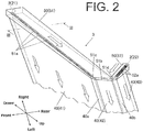
- FIG. 2 is an enlarged view of a part II in FIG. 1
- FIG. 3 is a cross-sectional view illustrating the illumination device 1 taken along line III-III of FIG. 2 .
- the illumination device 1 can be configured to illuminate a region across the front area to the sideward area (leftward area in the illustrated example).
- the illumination device 1 can include two light sources such as two light emitting diodes 2 (first and second LEDs 21 and 22), and a light guiding lens 3 configured to guide light from the LEDs 2 while being illuminated with the light (projecting the light).
- the light guiding lens 3 can be configured to include three light emission portions 40 and two light guiding portions 50.
- the three light emission portion 40 can include a first light emission portion 41, a second light emission portion 42, and a third light emission portion 43
- the two light guiding portions 50 can include a first light guiding portion 51 and a second light guiding portion 52 that can individually guide light rays emitted from the respective LEDs 2 to three light emission portions 40.
- the first light emission portion 41 can be a main light emission portion of the light guiding lens 3, and can be formed in an elongated, curved plate shape extending along a left-right direction when viewed from its front side.
- the first light emission portion 41 can have a front main face extending from the front end to the rear end and facing forward to leftward along its extending direction.
- the first light emission portion 41 can have a rear main face in which a plurality of reflecting cuts 41a can be formed substantially entirely.
- the third emission portion 43 can be formed in an elongated, curved plate shape having a width narrower than that of the first light emission portion 41.
- the third emission portion 43 can be provided along a direction in which the first emission portion 41 extends and have an upper main face facing upward and obliquely rearward. More specifically, the third light emission portion 43 can be connected to the upper end of the first light emission portion 41 via the second light emission portion 42 so as to project rearward from the upper end of the first light emission portion 41 via the second light emission portion 42 along the entire length of the first light emission portion 41.
- the third light emission portion 43 can have a lower main face in which a plurality of reflecting cuts 43a (illustrated in part in FIG. 1 only at an encircled region when see through the upper face) that are similar to those of the first light emission portion 41 can be formed substantially entirely.
- the second light emission portion 42 can be formed in an elongated, curved plate shape similar to the third light emission portion 43.
- the second light emission portion 42 can be provided along the first emission portion 41 and have a front main face facing obliquely upward.
- the second light emission portion 42 can be configured to connect the upper end portion of the first light emission portion 41 and the front end portion of the third light emission portion 43 along the entire length thereof like a chamfered shape therebetween.
- the second light emission portion 42 can be configured to be bent rearward with respect to the first light emission portion 41 and be bent downward with respect to the third light emission portion 43, and to be connected to the upper end portion of the first light emission portion 41 and the front end portion of the third light emission portion 43 extending therealong.
- the second light emission portion 42 can have a rear main face in which a plurality of reflecting cuts 42a (illustrated in part in FIG. 1 only at an encircled region when see through the front face) that are similar to those of the first light emission portion 41 can be formed substantially entirely.
- first light emission portion 41 and the second light emission portion 42 can have a connected face 40a formed therebetween and the second light emission portion 42 and the third light emission portion 43 can have a connected face 40b formed therebetween.
- the connected faces 40a and 40b can be formed along the entire lengths in a chamfered shape as illustrated in the enlarged view of FIG. 2 .
- the first light guiding portion 51 can receive and guide the light from the first LED 21 mainly to the first light emission portion 41 and partly to the second light emission portion 42 for illumination.
- the first light guiding portion 51 can be provided along the right end portion of the first light emission portion 41 so as to extend vertically.
- the first light guiding portion 51 can have a rectangular cross section in a plane extending in the front-rear direction and perpendicular to the extending direction (vertical direction).
- the first light guiding portion 51 can have a front face flush with the first light emission portion 41 and a rear portion projected rearward than the right end portion of the first light emission portion 41.
- the first light guiding portion 51 may be projected forward or both rearward and forward as long as the first light guiding portion 51 projects in the thickness direction of the first light emission portion 41 (in the illustrated example, projecting in the front-rear direction at the right end portion). Then, the first light guiding portion 51 can be formed to have a narrower width in the left-right direction toward its upper end side.
- the first light guiding portion 51 can have a lower end portion projected slightly downward more than the first light emission portion 41.
- the first LED 21 can be disposed to face to a portion of the first light guiding portion 51 projected rearward more than the first light emission portion 41. In the illustrated example, the first LED 21 can be disposed at the middle of the lower end portion of the first light guiding portion 51 in the front-rear direction.
- the first light guiding portion 51 can have a plurality of reflecting cuts 51a at its right end face that is rightward with respect to the right end portion of the first light emission portion 41.
- the reflecting cuts 51a can be formed side by side along the direction in which the first light guiding portion 51 extends (vertical direction).
- the first light guiding portion 51 can be formed to be slightly longer than the second light emission portion 42 in the front-rear direction, and have an upper end portion connected to the second light emission portion 42.
- the first light guiding portion 51 can have an inclined face 51b projected rearward than the first light emission portion 41 and inclined in a chamfered shape.
- the inclined face 51b can be located on the right side of the second light emission portion 43 so as to internally reflect the light guided upward through the first light guiding portion 51 toward the second light emission portion 42 (leftward in the drawing).
- the first light guiding portion 51 can have a chamfered inclined face 51c that is an upper end face of the first light guiding portion 51 located above the right end portion of the first light emission portion 41 or located above the plurality of reflecting cuts 51a.
- the inclined face 51c located on the right side of the connected face 40a can internally reflect the light, which has been guided upward through the first light guiding portion 51, leftward.
- the second light guiding portion 52 can be configured to guide the light from the second LED 22 to the third light emission portion 43 and in part to the second light emission portion 42 to irradiate them with light.
- the second light guiding portion 52 can be configured similarly to the first light guiding portion 51 except for its size, and to be provided to the right end portion of the third light emission portion 43 so as to extend long along the right end portion of the third light emission portion 43.
- the second light guiding portion 52 can be formed to have a rectangular cross section perpendicular to its extending direction and an upper face approximately flushing with the third emission portion 43 and projecting downward more than the right end portion of the third light emission portion 42. Note that the second light guiding portion 52 may project in the thickness direction of the third light emission portion 43 (approximately vertically at its right end portion).
- the second light guiding portion 52 can be formed to have a left-right width narrower toward its front side.
- the second light guiding portion 52 can have a rear end portion projecting slightly rearward more than the third light emission portion 43, and there can be disposed the second LED 22 at a portion projecting downward more than the third light emission portion 43 on its rear end face of the second light guiding portion 52.
- the second light guiding portion 52 can have a plurality of reflecting cuts 52a at its right end face that is rightward with respect to the right end portion of the third light emission portion 43.
- the reflecting cuts 52a can be formed side by side along the direction in which the second light guiding portion 52 extends.
- the second light guiding portion 52 can have a front end portion connected to the upper end portion of the first light guiding portion 51 and also to the second light emission portion 42.
- the second light guiding portion 52 can have a front end face of which a portion projecting downward more than the third light emission portion 43 can be overlapped with the upper portion of the inclined face 51b. With this configuration, the light that has been guided through the second light guiding portion 52 forward can be internally reflected by the upper portion of the inclined face 51b leftward toward the second light emission portion 42.
- the second light guiding portion 52 can have an inclined face 51d disposed in front of the right end portion of the third light emission portion 43 (forward of the third light emission portion 43 along its extending direction), or a portion disposed forward of the plurality of reflecting cuts of the third light emission portion 43.
- the inclined face 51d located on the right side of the connected face 40b can internally reflect the light, which has been guided forward through the second light guiding portion 52, leftward.
- the illumination device 1 of the present invention can be configured such that the light emitted from the first LED 21 can enter the first light guiding portion 51 through the lower end face of the first light guiding portion 51, which can extend vertically along the right end portion of the plate-shaped first light emission portion 41, at the portion of the lower end face projecting more than the first light emission portion 41 in its thickness direction (front-rear direction).
- the light can be incident on the projecting portion of the first light guiding portion 51 more than the first light emission portion 41, the light does not enter straightforwardly the first light emission portion 41 connected to the first light guiding portion 51, but the light can be appropriately guided through the first light guiding portion 51 partly up to the upper end side (farther side from the first LED 21) through the projection portion of the first light guiding portion 51.
- the light guided through the first light guiding portion 51 can be internally reflected by the plurality of reflecting cuts 51a formed at right end face of the first light guiding portion 51 in portions on the right side of the first light emission portion 41, so as to enter the first light emission portion 41.
- the light can be internally reflected by the plurality of reflecting cuts 41a formed on the rear face of the first light emission portion 41 to exit through the front face of the first light emission portion 41.
- the front face of the first light emission portion 41 can be illuminated with light, or the light can be projected through the front face.
- the illumination device 1 when compared with the conventional illumination device in which there is a gap between a light guiding portion and a light emission portion, the illumination device 1 made in accordance with the principles of the present invention can prevent the luminous flux utilization efficiency from deteriorating.
- the luminance unevenness of the light guiding lens 3 can be suppressed.
- the illumination device 1 can prevent the deterioration of the luminous flux utilization efficiency and suppress the luminance unevenness while the light guiding lens 3 can project light along its surface uniformly.
- the light guiding lens 3 can include the second light emission portion 42 that is connected to the first light emission portion 41 along the upper end portion of the first light emission portion 41 while being inclined with respect to the first light emission portion 41.
- the first light guiding portion 51 can be connected to the second light emission portion 42 at its upper end portion, and can have the inclined face 51b at its upper end face, with the inclined face 51b configured to internally reflect the light guided upward through the first light guiding portion 51 leftward to the second light emission portion 42. With this configuration, the light guided through the first light guiding portion 51 up to the upper end side can be utilized to illuminate the second light emission portion 42.
- the light from the first LED 21 can be projected through both surfaces of the first light emission portion 41 and the second light emission portion 42, thereby achieving a three-dimensional surface emission system.
- the light guiding lens 3 can include the third light emission portion 43 and the second light guiding portion 52 similar to the first light emission portion 41 and the first light guiding portion 51. Therefore, as in the first light emission portion 41, the third light emission portion 43 can project light along its surface uniformly, thereby also achieving a three-dimensional surface emission system.
- the first light emission portion 41, the third light emission portion 43, and the second light emission portion 42 between them can project light along their surfaces uniformly, thereby achieving a three-dimensional surface emission system with providing a higher aesthetic appearance.
- the first LED 21 as a single LED is disposed to face to the portion of the lower end face of the first light guiding portion 51 projecting rearward more than the first light emission portion 41, but this is not restrictive.
- a plurality of LEDs can be disposed to face to the lower end face of the first light guiding portion 51 projecting rearward.
- the same configuration can be applied to the second light guiding portion 52 and a plurality of LEDs instead of the second LED 22. This configuration can increase the light amount to illuminate the light emission portion 40 with.
- each of the light guiding portions 51 and 52 may be subjected to aluminum deposition to decrease the light leakage from the light guiding portions 51 and 52.
- a reflecting plate may be disposed on the right side of the respective light guiding portions 51 and 52 to reflect leaked light to re-enter the light guiding portions 51 and 52.
- the direction (posture) of the illumination device is not limited to that illustrated in the drawings.
- the illumination device made in accordance with the principles of the present invention may serve as other vehicle lighting fixtures such as a rear combination lamp, a turn signal lamp, a day-time running lamp, etc. Therefore, the position and direction (posture) of the illumination device may appropriately be determined in accordance with the product to which the illumination device is installed.
Landscapes
- Physics & Mathematics (AREA)
- Engineering & Computer Science (AREA)
- General Engineering & Computer Science (AREA)
- General Physics & Mathematics (AREA)
- Optics & Photonics (AREA)
- Microelectronics & Electronic Packaging (AREA)
- Planar Illumination Modules (AREA)
- Non-Portable Lighting Devices Or Systems Thereof (AREA)
Claims (4)
- Beleuchtungsvorrichtung (1), die Folgendes aufweist:eine erste Lichtquelle (21) zum Emittieren von Licht; undeine Lichtführungslinse (3) zum Aufnehmen von Licht von der ersten Lichtquelle (21) und zum Führen des Lichts, um das Licht zu projizieren, wobei die Lichtführungslinse (3) Folgendes aufweist:einen ersten Lichtemissionsteil (41) in einer Plattenform, der sich in einer vorbestimmten Richtung erstreckt und eine Hauptoberfläche mit einer Vielzahl von reflektierenden Einschnitten (41a) aufweist, die in dieser gebildet sind, undeinen ersten Lichtführungsteil (51), der an dem ersten Lichtemissionsteil (41) an einem Endteil von diesem in der vorbestimmten Richtung vorgesehen ist,wobei der erste Lichtführungsteil (51) mehr als der erste Lichtemissionsteil (41) in einer Dickenrichtung des ersten Lichtemissionsteils (41) vorragt und sich entlang des Endteils des ersten Lichtemissionsteils (41) erstreckt,wobei die erste Lichtquelle (21) so angeordnet ist, dass sie zu einem Teil einer Endfläche des ersten Lichtführungsteils (51) in einer Ausdehnungsrichtung weist, in der sich der erste Lichtführungsteil (51) erstreckt, wobei der Teil der Endfläche mehr als der erste Lichtemissionsteil (41) in der Ausdehnungsrichtung vorragt, wobei die vorbestimmte Richtung, die Ausdehnungsrichtung und die Dickenrichtung senkrecht zueinander sind,wobei ein Teil einer Endfläche des ersten Lichtführungsteils (51), der in der vorbestimmten Richtung bei einer Position in der vorbestimmten Richtung des ersten Lichtemissionsteils (41) angeordnet ist, eine Vielzahl von reflektierenden Einschnitten (51a) aufweist, die Seite an Seite in der Ausdehnungsrichtung angeordnet sind und die sich in der Dickenrichtung erstrecken, und zwar so weit wie es der erste Lichtemissionsteil (41) tut,wobei die erste Lichtquelle (21) Licht in der Ausdehnungsrichtung ausstrahlt, dadurch gekennzeichnet, dassdie Lichtführungslinse (3) einen zweiten Lichtemissionsteil (42) in Plattenform aufweist, der sich in der vorbestimmten Richtung erstreckt und eine Hauptoberfläche mit einer Vielzahl von reflektierenden Einschnitten (42a) aufweist, die darin gebildet sind,wobei sich der zweite Lichtemissionsteil (42) biegt und zu einer Seite hin geneigt ist, wo der erste Lichtführungsteil (51) in Bezug auf den ersten Lichtemissionsteil (41) vorragt, so dass er sich entlang des anderen Endteils des ersten Lichtemissionsteil (41) in der Ausdehnungsrichtung erstreckt und mit dem anderen Endteil verbunden ist,wobei der erste Lichtführungsteil (51) den anderen Endteil aufweist, der in der Ausdehnungsrichtung mit dem zweiten Lichtemissionsteil (42) verbunden werden soll, unddie andere Endfläche des ersten Lichtführungsteils (51) eine reflektierende Fläche (51b) aufweist, die der ersten Lichtquelle (21) entgegengesetzt ist, gebogen ist und geneigt ist, im Allgemeinen die gleiche Form wie der zweite Emissionsteil (42) aufweist und intern Licht reflektieren kann, das durch den ersten Lichtführungsteil (51) in der Ausdehnungsrichtung geführt worden ist, und zwar in der vorbestimmten Richtung zu dem zweiten Lichtemissionsteil (42).
- Beleuchtungsvorrichtung (2) gemäß Anspruch 1, dadurch gekennzeichnet, dass der erste Lichtführungsteil (51) so konfiguriert ist, dass er nur auf einer Seite der Hauptfläche des ersten Lichtemissionsteils (41) in der Dickensichtung vorragt.
- Beleuchtungsvorrichtung (1) gemäß Anspruch 1, dadurch gekennzeichnet, dass der Lichtführungsteil (3) Folgendes aufweist:einen dritten Lichtemissionsteil (43) in einer Plattenform, der sich in der vorbestimmten Richtung erstreckt und eine Hauptoberfläche mit einer Vielzahl von reflektierenden Einschnitten (43a) aufweist, die darin gebildet sind, undeinen zweiten Lichtführungsteil (52), der an dem dritten Lichtemissionsteil (43) bei einem Endteil des dritten Lichtemissionsteils (43) in der vorbestimmten Richtung vorgesehen ist,wobeider dritte Lichtemissionsteil (43) mit einem Endteil des zweiten Lichtemissionsteils (42) gegenüberliegend dem Endteil von diesem verbunden ist, wobei der erste Lichtemissionssteil (41) so verbunden ist, dass er in Bezug auf den zweiten Lichtemissionssteil (42) geneigt ist und sich entlang des Endteils erstreckt,wobei der zweite Lichtführungssteil (52) so konfiguriert ist, dass er mehr als der dritte Lichtemissionssteil (43) in einer Dickenrichtung des dritten Lichtemissionsteils (43) vorragt und sich entlang des Endteils des dritten Lichtemissionsteils (43) erstreckt,wobei die Beleuchtungsvorrichtung (1) eine zweite Lichtquelle (22) aufweist, die so angeordnet ist, dass sie zu dem zweiten Lichtführungssteil (52) bei einer Endfläche in einer Ausdehnungsrichtung weist, in der sich der zweite Lichtführungssteil (52) erstreckt, wobei die eine Endfläche auf einer Seite gegenüberliegend der Seite gelegen ist, wo der zweite Lichtemissionsteil (42) verbunden ist, wobei die eine Endfläche mehr als der dritte Lichtemissionsteil (43) vorragt,wobei ein Teil einer Endfläche in der vorbestimmten Richtung, der bei einer Position in der vorbestimmten Richtung des dritten Lichtemissionsteil (43) angeordnet ist, eine Vielzahl von reflektierenden Einschnitten (52a) aufweist, die Seite an Seite in der Ausdehnungsrichtung des zweiten Lichtführungsteils (52) angeordnet sind.
- Beleuchtungsvorrichtung (1) gemäß Anspruch 3, dadurch gekennzeichnet, dass
der zweite Lichtführungsteil (52) mit dem zweiten Lichtemissionsteil (42) bei dem anderen Endteil von diesen in der Ausdehnungsrichtung verbunden ist, und
sich die andere Endfläche des zweiten Lichtführungsteils (42) mit der reflektierenden Fläche des ersten Lichtführungsteils (51) überlappt.
Applications Claiming Priority (1)
| Application Number | Priority Date | Filing Date | Title |
|---|---|---|---|
| JP2015033573A JP6530928B2 (ja) | 2015-02-24 | 2015-02-24 | 照明装置 |
Publications (2)
| Publication Number | Publication Date |
|---|---|
| EP3062014A1 EP3062014A1 (de) | 2016-08-31 |
| EP3062014B1 true EP3062014B1 (de) | 2017-11-15 |
Family
ID=55701686
Family Applications (1)
| Application Number | Title | Priority Date | Filing Date |
|---|---|---|---|
| EP16157022.1A Active EP3062014B1 (de) | 2015-02-24 | 2016-02-23 | Beleuchtungsvorrichtung |
Country Status (3)
| Country | Link |
|---|---|
| US (1) | US10234615B2 (de) |
| EP (1) | EP3062014B1 (de) |
| JP (1) | JP6530928B2 (de) |
Families Citing this family (5)
| Publication number | Priority date | Publication date | Assignee | Title |
|---|---|---|---|---|
| JP6967394B2 (ja) * | 2017-08-09 | 2021-11-17 | 株式会社小糸製作所 | 導光体および車両用灯具 |
| PL3502552T3 (pl) * | 2017-12-21 | 2022-12-12 | Marelli Automotive Lighting Italy S.p.A. | Lampa pojazdu z częściami o różnych poziomach luminancji |
| JP7034750B2 (ja) * | 2018-02-09 | 2022-03-14 | スタンレー電気株式会社 | 車両用灯具 |
| JP7020259B2 (ja) * | 2018-04-09 | 2022-02-16 | トヨタ自動車株式会社 | 車両用灯具 |
| CN219014110U (zh) * | 2022-12-28 | 2023-05-12 | 法雷奥市光(中国)车灯有限公司 | 光学照射组件、照明设备以及机动车辆 |
Family Cites Families (22)
| Publication number | Priority date | Publication date | Assignee | Title |
|---|---|---|---|---|
| US5506929A (en) * | 1994-10-19 | 1996-04-09 | Clio Technologies, Inc. | Light expanding system for producing a linear or planar light beam from a point-like light source |
| DE69803297T2 (de) * | 1997-08-12 | 2002-08-22 | Breault Res Organization Inc | Doppelreflektierende linse |
| JP3835585B2 (ja) * | 1998-02-13 | 2006-10-18 | オムロン株式会社 | 面光源装置 |
| JP2004198591A (ja) * | 2002-12-17 | 2004-07-15 | Konica Minolta Holdings Inc | 表示装置とそれを備えたカメラ及び発光表示方法 |
| FR2853392B1 (fr) * | 2003-04-04 | 2006-06-16 | Sli Miniature Lighting Sa | Feu arriere, en particulier feu stop pour vehicule automobile |
| JP2005158362A (ja) * | 2003-11-21 | 2005-06-16 | Stanley Electric Co Ltd | 車両用灯具 |
| DE102005047793A1 (de) | 2005-10-05 | 2007-04-12 | Hella Kgaa Hueck & Co. | Beleuchtungseinrichtung für ein Kraftfahrzeug |
| DE102008048751A1 (de) * | 2008-09-25 | 2010-04-01 | Automotive Lighting Reutlingen Gmbh | Leuchte für Kraftfahrzeuge |
| DE102008056985A1 (de) | 2008-11-12 | 2010-05-20 | Hella Kgaa Hueck & Co. | Zierleuchteneinheit für Fahrzeuge |
| US20100246200A1 (en) * | 2009-03-30 | 2010-09-30 | Osram Sylvania Inc. | Automotive taillight light guide |
| JP2012190761A (ja) * | 2011-03-14 | 2012-10-04 | Koito Mfg Co Ltd | 車両用灯具 |
| JP2012190762A (ja) | 2011-03-14 | 2012-10-04 | Koito Mfg Co Ltd | 車両用灯具 |
| AT512056B1 (de) | 2011-11-08 | 2013-05-15 | Zizala Lichtsysteme Gmbh | Lichtleitelement sowie lichteinheit |
| JP2014041787A (ja) | 2012-08-23 | 2014-03-06 | Koito Mfg Co Ltd | 車両用灯具 |
| JP5995699B2 (ja) * | 2012-12-07 | 2016-09-21 | 株式会社小糸製作所 | 車両用灯具 |
| JP6164832B2 (ja) * | 2012-12-19 | 2017-07-19 | 株式会社小糸製作所 | 導光体および照明装置 |
| JP6266932B2 (ja) | 2013-01-16 | 2018-01-24 | 株式会社小糸製作所 | 車両用灯具 |
| JP6166541B2 (ja) * | 2013-01-30 | 2017-07-19 | スタンレー電気株式会社 | 車両用灯具 |
| JP6251985B2 (ja) | 2013-05-31 | 2017-12-27 | 市光工業株式会社 | 車両用灯具 |
| JP6292653B2 (ja) | 2013-07-02 | 2018-03-14 | 株式会社小糸製作所 | 車両用灯具 |
| DE102014005044A1 (de) | 2014-04-04 | 2014-09-18 | Daimler Ag | Lichtleiteranordnung und Beleuchtungseinrichtung |
| JP2016046120A (ja) * | 2014-08-25 | 2016-04-04 | スタンレー電気株式会社 | 車両用灯具 |
-
2015
- 2015-02-24 JP JP2015033573A patent/JP6530928B2/ja active Active
-
2016
- 2016-02-22 US US15/049,981 patent/US10234615B2/en active Active
- 2016-02-23 EP EP16157022.1A patent/EP3062014B1/de active Active
Non-Patent Citations (1)
| Title |
|---|
| None * |
Also Published As
| Publication number | Publication date |
|---|---|
| US20160245974A1 (en) | 2016-08-25 |
| JP2016157553A (ja) | 2016-09-01 |
| US10234615B2 (en) | 2019-03-19 |
| EP3062014A1 (de) | 2016-08-31 |
| JP6530928B2 (ja) | 2019-06-12 |
Similar Documents
| Publication | Publication Date | Title |
|---|---|---|
| CN104748034B (zh) | 具有线形显现图或平面显现图的机动车灯 | |
| EP2762770B1 (de) | Fahrzeugbeleuchtungseinheit | |
| JP6228863B2 (ja) | 車両用灯具 | |
| JP6560514B2 (ja) | 車両用灯具 | |
| CN106247278B (zh) | 导光透镜以及车辆用灯具 | |
| EP2562045B1 (de) | Fahrzeugbeleuchtungsvorrichtung | |
| EP3062014B1 (de) | Beleuchtungsvorrichtung | |
| JP2017147102A (ja) | 車両用灯具 | |
| JP2014029775A (ja) | 車両用前照灯 | |
| JP2009032564A (ja) | 車両用灯具、及び、車両用灯具に用いられる導光レンズ | |
| JP2011076858A (ja) | 車輌用灯具 | |
| EP3012522A1 (de) | Fahrzeugbeleuchtungsvorrichtung | |
| JP2011113855A (ja) | 車両用灯具 | |
| JP6918653B2 (ja) | 車両用灯具 | |
| JP2016194983A (ja) | 車両用灯具 | |
| JP2018055992A (ja) | 灯具ユニット | |
| JP6975587B2 (ja) | 車両用灯具 | |
| JP2014149963A (ja) | 車両用灯具 | |
| US20150003111A1 (en) | Led rear lamp, in particular for a bicycle | |
| CN104777546A (zh) | 分段式出光导光件及灯具 | |
| JP2016152142A (ja) | 車両用灯具 | |
| CN102788301A (zh) | 机动车辆灯具 | |
| JP6539484B2 (ja) | 車両用導光体、車両用灯具 | |
| KR102392552B1 (ko) | 차량용 램프 | |
| CN110630972A (zh) | 车辆用灯具 |
Legal Events
| Date | Code | Title | Description |
|---|---|---|---|
| PUAI | Public reference made under article 153(3) epc to a published international application that has entered the european phase |
Free format text: ORIGINAL CODE: 0009012 |
|
| AK | Designated contracting states |
Kind code of ref document: A1 Designated state(s): AL AT BE BG CH CY CZ DE DK EE ES FI FR GB GR HR HU IE IS IT LI LT LU LV MC MK MT NL NO PL PT RO RS SE SI SK SM TR |
|
| AX | Request for extension of the european patent |
Extension state: BA ME |
|
| 17P | Request for examination filed |
Effective date: 20170227 |
|
| RBV | Designated contracting states (corrected) |
Designated state(s): AL AT BE BG CH CY CZ DE DK EE ES FI FR GB GR HR HU IE IS IT LI LT LU LV MC MK MT NL NO PL PT RO RS SE SI SK SM TR |
|
| GRAJ | Information related to disapproval of communication of intention to grant by the applicant or resumption of examination proceedings by the epo deleted |
Free format text: ORIGINAL CODE: EPIDOSDIGR1 |
|
| GRAP | Despatch of communication of intention to grant a patent |
Free format text: ORIGINAL CODE: EPIDOSNIGR1 |
|
| INTG | Intention to grant announced |
Effective date: 20170530 |
|
| GRAS | Grant fee paid |
Free format text: ORIGINAL CODE: EPIDOSNIGR3 |
|
| GRAA | (expected) grant |
Free format text: ORIGINAL CODE: 0009210 |
|
| AK | Designated contracting states |
Kind code of ref document: B1 Designated state(s): AL AT BE BG CH CY CZ DE DK EE ES FI FR GB GR HR HU IE IS IT LI LT LU LV MC MK MT NL NO PL PT RO RS SE SI SK SM TR |
|
| REG | Reference to a national code |
Ref country code: CH Ref legal event code: EP Ref country code: GB Ref legal event code: FG4D Ref country code: AT Ref legal event code: REF Ref document number: 946647 Country of ref document: AT Kind code of ref document: T Effective date: 20171115 |
|
| REG | Reference to a national code |
Ref country code: DE Ref legal event code: R079 Ref document number: 602016000783 Country of ref document: DE Free format text: PREVIOUS MAIN CLASS: F21S0008100000 Ipc: F21S0043000000 |
|
| REG | Reference to a national code |
Ref country code: IE Ref legal event code: FG4D |
|
| REG | Reference to a national code |
Ref country code: DE Ref legal event code: R096 Ref document number: 602016000783 Country of ref document: DE |
|
| REG | Reference to a national code |
Ref country code: FR Ref legal event code: PLFP Year of fee payment: 3 |
|
| REG | Reference to a national code |
Ref country code: NL Ref legal event code: MP Effective date: 20171115 |
|
| REG | Reference to a national code |
Ref country code: LT Ref legal event code: MG4D |
|
| REG | Reference to a national code |
Ref country code: AT Ref legal event code: MK05 Ref document number: 946647 Country of ref document: AT Kind code of ref document: T Effective date: 20171115 |
|
| PG25 | Lapsed in a contracting state [announced via postgrant information from national office to epo] |
Ref country code: NL Free format text: LAPSE BECAUSE OF FAILURE TO SUBMIT A TRANSLATION OF THE DESCRIPTION OR TO PAY THE FEE WITHIN THE PRESCRIBED TIME-LIMIT Effective date: 20171115 Ref country code: NO Free format text: LAPSE BECAUSE OF FAILURE TO SUBMIT A TRANSLATION OF THE DESCRIPTION OR TO PAY THE FEE WITHIN THE PRESCRIBED TIME-LIMIT Effective date: 20180215 Ref country code: SE Free format text: LAPSE BECAUSE OF FAILURE TO SUBMIT A TRANSLATION OF THE DESCRIPTION OR TO PAY THE FEE WITHIN THE PRESCRIBED TIME-LIMIT Effective date: 20171115 Ref country code: FI Free format text: LAPSE BECAUSE OF FAILURE TO SUBMIT A TRANSLATION OF THE DESCRIPTION OR TO PAY THE FEE WITHIN THE PRESCRIBED TIME-LIMIT Effective date: 20171115 Ref country code: LT Free format text: LAPSE BECAUSE OF FAILURE TO SUBMIT A TRANSLATION OF THE DESCRIPTION OR TO PAY THE FEE WITHIN THE PRESCRIBED TIME-LIMIT Effective date: 20171115 Ref country code: ES Free format text: LAPSE BECAUSE OF FAILURE TO SUBMIT A TRANSLATION OF THE DESCRIPTION OR TO PAY THE FEE WITHIN THE PRESCRIBED TIME-LIMIT Effective date: 20171115 |
|
| PG25 | Lapsed in a contracting state [announced via postgrant information from national office to epo] |
Ref country code: AT Free format text: LAPSE BECAUSE OF FAILURE TO SUBMIT A TRANSLATION OF THE DESCRIPTION OR TO PAY THE FEE WITHIN THE PRESCRIBED TIME-LIMIT Effective date: 20171115 Ref country code: RS Free format text: LAPSE BECAUSE OF FAILURE TO SUBMIT A TRANSLATION OF THE DESCRIPTION OR TO PAY THE FEE WITHIN THE PRESCRIBED TIME-LIMIT Effective date: 20171115 Ref country code: HR Free format text: LAPSE BECAUSE OF FAILURE TO SUBMIT A TRANSLATION OF THE DESCRIPTION OR TO PAY THE FEE WITHIN THE PRESCRIBED TIME-LIMIT Effective date: 20171115 Ref country code: GR Free format text: LAPSE BECAUSE OF FAILURE TO SUBMIT A TRANSLATION OF THE DESCRIPTION OR TO PAY THE FEE WITHIN THE PRESCRIBED TIME-LIMIT Effective date: 20180216 Ref country code: BG Free format text: LAPSE BECAUSE OF FAILURE TO SUBMIT A TRANSLATION OF THE DESCRIPTION OR TO PAY THE FEE WITHIN THE PRESCRIBED TIME-LIMIT Effective date: 20180215 Ref country code: LV Free format text: LAPSE BECAUSE OF FAILURE TO SUBMIT A TRANSLATION OF THE DESCRIPTION OR TO PAY THE FEE WITHIN THE PRESCRIBED TIME-LIMIT Effective date: 20171115 |
|
| PG25 | Lapsed in a contracting state [announced via postgrant information from national office to epo] |
Ref country code: SK Free format text: LAPSE BECAUSE OF FAILURE TO SUBMIT A TRANSLATION OF THE DESCRIPTION OR TO PAY THE FEE WITHIN THE PRESCRIBED TIME-LIMIT Effective date: 20171115 Ref country code: CZ Free format text: LAPSE BECAUSE OF FAILURE TO SUBMIT A TRANSLATION OF THE DESCRIPTION OR TO PAY THE FEE WITHIN THE PRESCRIBED TIME-LIMIT Effective date: 20171115 Ref country code: EE Free format text: LAPSE BECAUSE OF FAILURE TO SUBMIT A TRANSLATION OF THE DESCRIPTION OR TO PAY THE FEE WITHIN THE PRESCRIBED TIME-LIMIT Effective date: 20171115 Ref country code: CY Free format text: LAPSE BECAUSE OF FAILURE TO SUBMIT A TRANSLATION OF THE DESCRIPTION OR TO PAY THE FEE WITHIN THE PRESCRIBED TIME-LIMIT Effective date: 20171115 Ref country code: DK Free format text: LAPSE BECAUSE OF FAILURE TO SUBMIT A TRANSLATION OF THE DESCRIPTION OR TO PAY THE FEE WITHIN THE PRESCRIBED TIME-LIMIT Effective date: 20171115 |
|
| REG | Reference to a national code |
Ref country code: DE Ref legal event code: R097 Ref document number: 602016000783 Country of ref document: DE |
|
| PG25 | Lapsed in a contracting state [announced via postgrant information from national office to epo] |
Ref country code: RO Free format text: LAPSE BECAUSE OF FAILURE TO SUBMIT A TRANSLATION OF THE DESCRIPTION OR TO PAY THE FEE WITHIN THE PRESCRIBED TIME-LIMIT Effective date: 20171115 Ref country code: PL Free format text: LAPSE BECAUSE OF FAILURE TO SUBMIT A TRANSLATION OF THE DESCRIPTION OR TO PAY THE FEE WITHIN THE PRESCRIBED TIME-LIMIT Effective date: 20171115 Ref country code: SM Free format text: LAPSE BECAUSE OF FAILURE TO SUBMIT A TRANSLATION OF THE DESCRIPTION OR TO PAY THE FEE WITHIN THE PRESCRIBED TIME-LIMIT Effective date: 20171115 Ref country code: IT Free format text: LAPSE BECAUSE OF FAILURE TO SUBMIT A TRANSLATION OF THE DESCRIPTION OR TO PAY THE FEE WITHIN THE PRESCRIBED TIME-LIMIT Effective date: 20171115 |
|
| PLBE | No opposition filed within time limit |
Free format text: ORIGINAL CODE: 0009261 |
|
| STAA | Information on the status of an ep patent application or granted ep patent |
Free format text: STATUS: NO OPPOSITION FILED WITHIN TIME LIMIT |
|
| PG25 | Lapsed in a contracting state [announced via postgrant information from national office to epo] |
Ref country code: MC Free format text: LAPSE BECAUSE OF FAILURE TO SUBMIT A TRANSLATION OF THE DESCRIPTION OR TO PAY THE FEE WITHIN THE PRESCRIBED TIME-LIMIT Effective date: 20171115 |
|
| 26N | No opposition filed |
Effective date: 20180817 |
|
| REG | Reference to a national code |
Ref country code: IE Ref legal event code: MM4A |
|
| REG | Reference to a national code |
Ref country code: BE Ref legal event code: MM Effective date: 20180228 |
|
| PG25 | Lapsed in a contracting state [announced via postgrant information from national office to epo] |
Ref country code: SI Free format text: LAPSE BECAUSE OF FAILURE TO SUBMIT A TRANSLATION OF THE DESCRIPTION OR TO PAY THE FEE WITHIN THE PRESCRIBED TIME-LIMIT Effective date: 20171115 Ref country code: LU Free format text: LAPSE BECAUSE OF NON-PAYMENT OF DUE FEES Effective date: 20180223 |
|
| PG25 | Lapsed in a contracting state [announced via postgrant information from national office to epo] |
Ref country code: IE Free format text: LAPSE BECAUSE OF NON-PAYMENT OF DUE FEES Effective date: 20180223 |
|
| PG25 | Lapsed in a contracting state [announced via postgrant information from national office to epo] |
Ref country code: BE Free format text: LAPSE BECAUSE OF NON-PAYMENT OF DUE FEES Effective date: 20180228 |
|
| REG | Reference to a national code |
Ref country code: CH Ref legal event code: PL |
|
| PG25 | Lapsed in a contracting state [announced via postgrant information from national office to epo] |
Ref country code: CH Free format text: LAPSE BECAUSE OF NON-PAYMENT OF DUE FEES Effective date: 20190228 Ref country code: LI Free format text: LAPSE BECAUSE OF NON-PAYMENT OF DUE FEES Effective date: 20190228 |
|
| PG25 | Lapsed in a contracting state [announced via postgrant information from national office to epo] |
Ref country code: MT Free format text: LAPSE BECAUSE OF NON-PAYMENT OF DUE FEES Effective date: 20180223 |
|
| PG25 | Lapsed in a contracting state [announced via postgrant information from national office to epo] |
Ref country code: TR Free format text: LAPSE BECAUSE OF FAILURE TO SUBMIT A TRANSLATION OF THE DESCRIPTION OR TO PAY THE FEE WITHIN THE PRESCRIBED TIME-LIMIT Effective date: 20171115 |
|
| PG25 | Lapsed in a contracting state [announced via postgrant information from national office to epo] |
Ref country code: PT Free format text: LAPSE BECAUSE OF FAILURE TO SUBMIT A TRANSLATION OF THE DESCRIPTION OR TO PAY THE FEE WITHIN THE PRESCRIBED TIME-LIMIT Effective date: 20171115 |
|
| PG25 | Lapsed in a contracting state [announced via postgrant information from national office to epo] |
Ref country code: MK Free format text: LAPSE BECAUSE OF NON-PAYMENT OF DUE FEES Effective date: 20171115 Ref country code: HU Free format text: LAPSE BECAUSE OF FAILURE TO SUBMIT A TRANSLATION OF THE DESCRIPTION OR TO PAY THE FEE WITHIN THE PRESCRIBED TIME-LIMIT; INVALID AB INITIO Effective date: 20160223 |
|
| PG25 | Lapsed in a contracting state [announced via postgrant information from national office to epo] |
Ref country code: AL Free format text: LAPSE BECAUSE OF FAILURE TO SUBMIT A TRANSLATION OF THE DESCRIPTION OR TO PAY THE FEE WITHIN THE PRESCRIBED TIME-LIMIT Effective date: 20171115 Ref country code: IS Free format text: LAPSE BECAUSE OF FAILURE TO SUBMIT A TRANSLATION OF THE DESCRIPTION OR TO PAY THE FEE WITHIN THE PRESCRIBED TIME-LIMIT Effective date: 20180315 |
|
| PGFP | Annual fee paid to national office [announced via postgrant information from national office to epo] |
Ref country code: GB Payment date: 20240108 Year of fee payment: 9 |
|
| PGFP | Annual fee paid to national office [announced via postgrant information from national office to epo] |
Ref country code: FR Payment date: 20240103 Year of fee payment: 9 |
|
| PGFP | Annual fee paid to national office [announced via postgrant information from national office to epo] |
Ref country code: DE Payment date: 20241231 Year of fee payment: 10 |
|
| GBPC | Gb: european patent ceased through non-payment of renewal fee |
Effective date: 20250223 |
|
| PG25 | Lapsed in a contracting state [announced via postgrant information from national office to epo] |
Ref country code: GB Free format text: LAPSE BECAUSE OF NON-PAYMENT OF DUE FEES Effective date: 20250223 |
|
| PG25 | Lapsed in a contracting state [announced via postgrant information from national office to epo] |
Ref country code: FR Free format text: LAPSE BECAUSE OF NON-PAYMENT OF DUE FEES Effective date: 20250228 |