EP3062015B1 - Leuchtvorrichtung für kraftfahrzeug - Google Patents
Leuchtvorrichtung für kraftfahrzeug Download PDFInfo
- Publication number
- EP3062015B1 EP3062015B1 EP16156974.4A EP16156974A EP3062015B1 EP 3062015 B1 EP3062015 B1 EP 3062015B1 EP 16156974 A EP16156974 A EP 16156974A EP 3062015 B1 EP3062015 B1 EP 3062015B1
- Authority
- EP
- European Patent Office
- Prior art keywords
- light
- light guide
- guide layer
- injection
- sub
- Prior art date
- Legal status (The legal status is an assumption and is not a legal conclusion. Google has not performed a legal analysis and makes no representation as to the accuracy of the status listed.)
- Active
Links
Images



Classifications
-
- F—MECHANICAL ENGINEERING; LIGHTING; HEATING; WEAPONS; BLASTING
- F21—LIGHTING
- F21S—NON-PORTABLE LIGHTING DEVICES; SYSTEMS THEREOF; VEHICLE LIGHTING DEVICES SPECIALLY ADAPTED FOR VEHICLE EXTERIORS
- F21S43/00—Signalling devices specially adapted for vehicle exteriors, e.g. brake lamps, direction indicator lights or reversing lights
- F21S43/20—Signalling devices specially adapted for vehicle exteriors, e.g. brake lamps, direction indicator lights or reversing lights characterised by refractors, transparent cover plates, light guides or filters
- F21S43/235—Light guides
-
- G—PHYSICS
- G02—OPTICS
- G02B—OPTICAL ELEMENTS, SYSTEMS OR APPARATUS
- G02B6/00—Light guides; Structural details of arrangements comprising light guides and other optical elements, e.g. couplings
- G02B6/0001—Light guides; Structural details of arrangements comprising light guides and other optical elements, e.g. couplings specially adapted for lighting devices or systems
- G02B6/0011—Light guides; Structural details of arrangements comprising light guides and other optical elements, e.g. couplings specially adapted for lighting devices or systems the light guides being planar or of plate-like form
- G02B6/0033—Means for improving the coupling-out of light from the light guide
- G02B6/0035—Means for improving the coupling-out of light from the light guide provided on the surface of the light guide or in the bulk of it
- G02B6/0038—Linear indentations or grooves, e.g. arc-shaped grooves or meandering grooves, extending over the full length or width of the light guide
-
- F—MECHANICAL ENGINEERING; LIGHTING; HEATING; WEAPONS; BLASTING
- F21—LIGHTING
- F21S—NON-PORTABLE LIGHTING DEVICES; SYSTEMS THEREOF; VEHICLE LIGHTING DEVICES SPECIALLY ADAPTED FOR VEHICLE EXTERIORS
- F21S41/00—Illuminating devices specially adapted for vehicle exteriors, e.g. headlamps
- F21S41/10—Illuminating devices specially adapted for vehicle exteriors, e.g. headlamps characterised by the light source
- F21S41/14—Illuminating devices specially adapted for vehicle exteriors, e.g. headlamps characterised by the light source characterised by the type of light source
- F21S41/141—Light emitting diodes [LED]
-
- F—MECHANICAL ENGINEERING; LIGHTING; HEATING; WEAPONS; BLASTING
- F21—LIGHTING
- F21S—NON-PORTABLE LIGHTING DEVICES; SYSTEMS THEREOF; VEHICLE LIGHTING DEVICES SPECIALLY ADAPTED FOR VEHICLE EXTERIORS
- F21S41/00—Illuminating devices specially adapted for vehicle exteriors, e.g. headlamps
- F21S41/20—Illuminating devices specially adapted for vehicle exteriors, e.g. headlamps characterised by refractors, transparent cover plates, light guides or filters
- F21S41/24—Light guides
-
- F—MECHANICAL ENGINEERING; LIGHTING; HEATING; WEAPONS; BLASTING
- F21—LIGHTING
- F21S—NON-PORTABLE LIGHTING DEVICES; SYSTEMS THEREOF; VEHICLE LIGHTING DEVICES SPECIALLY ADAPTED FOR VEHICLE EXTERIORS
- F21S43/00—Signalling devices specially adapted for vehicle exteriors, e.g. brake lamps, direction indicator lights or reversing lights
-
- F—MECHANICAL ENGINEERING; LIGHTING; HEATING; WEAPONS; BLASTING
- F21—LIGHTING
- F21S—NON-PORTABLE LIGHTING DEVICES; SYSTEMS THEREOF; VEHICLE LIGHTING DEVICES SPECIALLY ADAPTED FOR VEHICLE EXTERIORS
- F21S43/00—Signalling devices specially adapted for vehicle exteriors, e.g. brake lamps, direction indicator lights or reversing lights
- F21S43/10—Signalling devices specially adapted for vehicle exteriors, e.g. brake lamps, direction indicator lights or reversing lights characterised by the light source
- F21S43/13—Signalling devices specially adapted for vehicle exteriors, e.g. brake lamps, direction indicator lights or reversing lights characterised by the light source characterised by the type of light source
- F21S43/14—Light emitting diodes [LED]
-
- F—MECHANICAL ENGINEERING; LIGHTING; HEATING; WEAPONS; BLASTING
- F21—LIGHTING
- F21S—NON-PORTABLE LIGHTING DEVICES; SYSTEMS THEREOF; VEHICLE LIGHTING DEVICES SPECIALLY ADAPTED FOR VEHICLE EXTERIORS
- F21S43/00—Signalling devices specially adapted for vehicle exteriors, e.g. brake lamps, direction indicator lights or reversing lights
- F21S43/20—Signalling devices specially adapted for vehicle exteriors, e.g. brake lamps, direction indicator lights or reversing lights characterised by refractors, transparent cover plates, light guides or filters
- F21S43/235—Light guides
- F21S43/236—Light guides characterised by the shape of the light guide
- F21S43/239—Light guides characterised by the shape of the light guide plate-shaped
-
- F—MECHANICAL ENGINEERING; LIGHTING; HEATING; WEAPONS; BLASTING
- F21—LIGHTING
- F21S—NON-PORTABLE LIGHTING DEVICES; SYSTEMS THEREOF; VEHICLE LIGHTING DEVICES SPECIALLY ADAPTED FOR VEHICLE EXTERIORS
- F21S43/00—Signalling devices specially adapted for vehicle exteriors, e.g. brake lamps, direction indicator lights or reversing lights
- F21S43/20—Signalling devices specially adapted for vehicle exteriors, e.g. brake lamps, direction indicator lights or reversing lights characterised by refractors, transparent cover plates, light guides or filters
- F21S43/235—Light guides
- F21S43/242—Light guides characterised by the emission area
- F21S43/243—Light guides characterised by the emission area emitting light from one or more of its extremities
-
- F—MECHANICAL ENGINEERING; LIGHTING; HEATING; WEAPONS; BLASTING
- F21—LIGHTING
- F21S—NON-PORTABLE LIGHTING DEVICES; SYSTEMS THEREOF; VEHICLE LIGHTING DEVICES SPECIALLY ADAPTED FOR VEHICLE EXTERIORS
- F21S43/00—Signalling devices specially adapted for vehicle exteriors, e.g. brake lamps, direction indicator lights or reversing lights
- F21S43/20—Signalling devices specially adapted for vehicle exteriors, e.g. brake lamps, direction indicator lights or reversing lights characterised by refractors, transparent cover plates, light guides or filters
- F21S43/235—Light guides
- F21S43/242—Light guides characterised by the emission area
- F21S43/245—Light guides characterised by the emission area emitting light from one or more of its major surfaces
-
- G—PHYSICS
- G02—OPTICS
- G02B—OPTICAL ELEMENTS, SYSTEMS OR APPARATUS
- G02B6/00—Light guides; Structural details of arrangements comprising light guides and other optical elements, e.g. couplings
- G02B6/0001—Light guides; Structural details of arrangements comprising light guides and other optical elements, e.g. couplings specially adapted for lighting devices or systems
- G02B6/0011—Light guides; Structural details of arrangements comprising light guides and other optical elements, e.g. couplings specially adapted for lighting devices or systems the light guides being planar or of plate-like form
- G02B6/0013—Means for improving the coupling-in of light from the light source into the light guide
- G02B6/0015—Means for improving the coupling-in of light from the light source into the light guide provided on the surface of the light guide or in the bulk of it
- G02B6/0018—Redirecting means on the surface of the light guide
-
- G—PHYSICS
- G02—OPTICS
- G02B—OPTICAL ELEMENTS, SYSTEMS OR APPARATUS
- G02B6/00—Light guides; Structural details of arrangements comprising light guides and other optical elements, e.g. couplings
- G02B6/0001—Light guides; Structural details of arrangements comprising light guides and other optical elements, e.g. couplings specially adapted for lighting devices or systems
- G02B6/0011—Light guides; Structural details of arrangements comprising light guides and other optical elements, e.g. couplings specially adapted for lighting devices or systems the light guides being planar or of plate-like form
- G02B6/0013—Means for improving the coupling-in of light from the light source into the light guide
- G02B6/0015—Means for improving the coupling-in of light from the light source into the light guide provided on the surface of the light guide or in the bulk of it
- G02B6/002—Means for improving the coupling-in of light from the light source into the light guide provided on the surface of the light guide or in the bulk of it by shaping at least a portion of the light guide, e.g. with collimating, focussing or diverging surfaces
-
- G—PHYSICS
- G02—OPTICS
- G02B—OPTICAL ELEMENTS, SYSTEMS OR APPARATUS
- G02B6/00—Light guides; Structural details of arrangements comprising light guides and other optical elements, e.g. couplings
- G02B6/0001—Light guides; Structural details of arrangements comprising light guides and other optical elements, e.g. couplings specially adapted for lighting devices or systems
- G02B6/0011—Light guides; Structural details of arrangements comprising light guides and other optical elements, e.g. couplings specially adapted for lighting devices or systems the light guides being planar or of plate-like form
- G02B6/0013—Means for improving the coupling-in of light from the light source into the light guide
- G02B6/0023—Means for improving the coupling-in of light from the light source into the light guide provided by one optical element, or plurality thereof, placed between the light guide and the light source, or around the light source
-
- G—PHYSICS
- G02—OPTICS
- G02B—OPTICAL ELEMENTS, SYSTEMS OR APPARATUS
- G02B6/00—Light guides; Structural details of arrangements comprising light guides and other optical elements, e.g. couplings
- G02B6/0001—Light guides; Structural details of arrangements comprising light guides and other optical elements, e.g. couplings specially adapted for lighting devices or systems
- G02B6/0011—Light guides; Structural details of arrangements comprising light guides and other optical elements, e.g. couplings specially adapted for lighting devices or systems the light guides being planar or of plate-like form
- G02B6/0033—Means for improving the coupling-out of light from the light guide
- G02B6/0035—Means for improving the coupling-out of light from the light guide provided on the surface of the light guide or in the bulk of it
- G02B6/004—Scattering dots or dot-like elements, e.g. microbeads, scattering particles, nanoparticles
- G02B6/0043—Scattering dots or dot-like elements, e.g. microbeads, scattering particles, nanoparticles provided on the surface of the light guide
-
- G—PHYSICS
- G02—OPTICS
- G02B—OPTICAL ELEMENTS, SYSTEMS OR APPARATUS
- G02B6/00—Light guides; Structural details of arrangements comprising light guides and other optical elements, e.g. couplings
- G02B6/0001—Light guides; Structural details of arrangements comprising light guides and other optical elements, e.g. couplings specially adapted for lighting devices or systems
- G02B6/0011—Light guides; Structural details of arrangements comprising light guides and other optical elements, e.g. couplings specially adapted for lighting devices or systems the light guides being planar or of plate-like form
- G02B6/0033—Means for improving the coupling-out of light from the light guide
- G02B6/0035—Means for improving the coupling-out of light from the light guide provided on the surface of the light guide or in the bulk of it
- G02B6/0045—Means for improving the coupling-out of light from the light guide provided on the surface of the light guide or in the bulk of it by shaping at least a portion of the light guide
- G02B6/0046—Tapered light guide, e.g. wedge-shaped light guide
- G02B6/0048—Tapered light guide, e.g. wedge-shaped light guide with stepwise taper
-
- B—PERFORMING OPERATIONS; TRANSPORTING
- B60—VEHICLES IN GENERAL
- B60Q—ARRANGEMENT OF SIGNALLING OR LIGHTING DEVICES, THE MOUNTING OR SUPPORTING THEREOF OR CIRCUITS THEREFOR, FOR VEHICLES IN GENERAL
- B60Q3/00—Arrangement of lighting devices for vehicle interiors; Lighting devices specially adapted for vehicle interiors
- B60Q3/60—Arrangement of lighting devices for vehicle interiors; Lighting devices specially adapted for vehicle interiors characterised by optical aspects
- B60Q3/62—Arrangement of lighting devices for vehicle interiors; Lighting devices specially adapted for vehicle interiors characterised by optical aspects using light guides
- B60Q3/64—Arrangement of lighting devices for vehicle interiors; Lighting devices specially adapted for vehicle interiors characterised by optical aspects using light guides for a single lighting device
-
- F—MECHANICAL ENGINEERING; LIGHTING; HEATING; WEAPONS; BLASTING
- F21—LIGHTING
- F21W—INDEXING SCHEME ASSOCIATED WITH SUBCLASSES F21K, F21L, F21S and F21V, RELATING TO USES OR APPLICATIONS OF LIGHTING DEVICES OR SYSTEMS
- F21W2102/00—Exterior vehicle lighting devices for illuminating purposes
-
- F—MECHANICAL ENGINEERING; LIGHTING; HEATING; WEAPONS; BLASTING
- F21—LIGHTING
- F21W—INDEXING SCHEME ASSOCIATED WITH SUBCLASSES F21K, F21L, F21S and F21V, RELATING TO USES OR APPLICATIONS OF LIGHTING DEVICES OR SYSTEMS
- F21W2103/00—Exterior vehicle lighting devices for signalling purposes
-
- F—MECHANICAL ENGINEERING; LIGHTING; HEATING; WEAPONS; BLASTING
- F21—LIGHTING
- F21W—INDEXING SCHEME ASSOCIATED WITH SUBCLASSES F21K, F21L, F21S and F21V, RELATING TO USES OR APPLICATIONS OF LIGHTING DEVICES OR SYSTEMS
- F21W2103/00—Exterior vehicle lighting devices for signalling purposes
- F21W2103/20—Direction indicator lights
-
- F—MECHANICAL ENGINEERING; LIGHTING; HEATING; WEAPONS; BLASTING
- F21—LIGHTING
- F21W—INDEXING SCHEME ASSOCIATED WITH SUBCLASSES F21K, F21L, F21S and F21V, RELATING TO USES OR APPLICATIONS OF LIGHTING DEVICES OR SYSTEMS
- F21W2106/00—Interior vehicle lighting devices
-
- F—MECHANICAL ENGINEERING; LIGHTING; HEATING; WEAPONS; BLASTING
- F21—LIGHTING
- F21W—INDEXING SCHEME ASSOCIATED WITH SUBCLASSES F21K, F21L, F21S and F21V, RELATING TO USES OR APPLICATIONS OF LIGHTING DEVICES OR SYSTEMS
- F21W2107/00—Use or application of lighting devices on or in particular types of vehicles
- F21W2107/10—Use or application of lighting devices on or in particular types of vehicles for land vehicles
-
- G—PHYSICS
- G02—OPTICS
- G02B—OPTICAL ELEMENTS, SYSTEMS OR APPARATUS
- G02B6/00—Light guides; Structural details of arrangements comprising light guides and other optical elements, e.g. couplings
- G02B6/0001—Light guides; Structural details of arrangements comprising light guides and other optical elements, e.g. couplings specially adapted for lighting devices or systems
- G02B6/0011—Light guides; Structural details of arrangements comprising light guides and other optical elements, e.g. couplings specially adapted for lighting devices or systems the light guides being planar or of plate-like form
- G02B6/0065—Manufacturing aspects; Material aspects
Definitions
- the present invention relates to a vehicle lighting device, comprising a light guide sheet.
- a preferred application of the invention is the field of automotive equipment for the production of luminous flux serving to signal the presence of the vehicle and / or to illuminate part of the environment of the vehicle.
- the shape of the lighting and / or signaling lights plays a preponderant role in the search for a style and an original aesthetic which will allow the motor vehicle to be recognized from afar.
- the document 2013/117755 A1 discloses a "backlight" with decoupling zones while the documents US 2011/0187967 A1 and US 2009/0147353 A1 show light guiding layers with decoupling zones.
- a light guide 1 is illuminated with light rays 2.
- the light can be reflected or refracted at the border between two different media depending on the value of their index n and n '. According to Snell-Descartes law, the light beam changes direction while passing from one medium to another.
- the zone 3 constitutes an optical decoupling zone allowing the light rays 2 to be deflected and thus to be refracted towards the external environment to exit the guide 1 and to propagate in a direction of illumination.
- the light guide 1 behaves in its lower faces like a mirror, which generates reflections and phantom patterns inside the guide 1, harming the correct reading of the decorative optical patterns. This is in addition to the refracted beams which also come out of the light guide 1 ( figure 5 ).
- the present invention aims to remedy these drawbacks.
- the light guide sheet is locally covered with a light absorbing material.
- a light absorbing material is present on one or more predetermined areas.
- the material absorbs between 60% and 100% of the light rays which encounter it, preferably at least between 90% and 100%.
- the light generator can comprise at least one semiconductor emitting element, in particular a light emitting diode.
- the device may include a collimator and / or a light guide receiving the light rays from the light source and returning them towards the light guide sheet.
- the collimator and / or the light guide may be integral with the guide sheet.
- the light generator can be integrated into the light guide sheet.
- the light absorbing material can be an opaque material.
- the optical decoupling zones may be able to send the light in a direction identical to the direction of the light coming from the light generator.
- the optical decoupling zones can be arranged on a first face of the light guide sheet and the absorber material.
- light can be disposed on the whole of a second face of the light guide sheet opposite to this first face.
- the first face is the upper face of the guide ply and the opposite face is the lower face of the guide face.
- the optical decoupling zones can be arranged on the second face, in particular the lower face, of the light guide sheet and the light absorbing material can be placed on the second face. of the light guide sheet, between the optical decoupling zones.
- the optical decoupling zones can be arranged on the walls of the light guide sheet, these walls being oriented so as to form an angle, in particular an angle of 90 °, with the first wall and the material.
- light absorber can be disposed on the whole of the second face of the light guide web.
- the subject of the invention is also a mold for a light guide for a motor vehicle lighting device, comprising at least a first part comprising at least one cavity, and at least a second part comprising at least a first and a second sub-parts. , at least one of the first and second sub-parts comprises at least one cavity. At least one of the first and second parts is movable so that each of the sub-parts is able to come into contact successively with the first part.
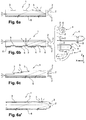
- a lighting or signaling device comprises a light generator, which in this example comprises a collimator 4, as well as a light guide sheet 1.
- the light rays 2 coming from the collimator 4 are emitted in direction of the guide sheet 1 along a horizontal axis x.
- collimators 4 Four possible examples of collimators 4 are illustrated on figure 6 , each collimator 4 possibly being provided with at least one light source 5, such as a light-emitting diode.
- the light collimated by the collimator 4 enters the guide sheet 1.
- the guide sheet 1 is provided with areas 3 of optical decoupling, in particular areas 3 of diffractive optical decoupling, allowing the light rays 2 to be deflected and thus be refracted towards the outside environment to leave the guide sheet 1 and propagate in a direction of illumination.
- the optical decoupling zones 3 can be obtained for example by graining, streaking, or else by the use of optical balls or inclined facets, in particular of the micro-prism type.
- the decoupling elements of the zones 3, such as the facets or striations, form reflecting surfaces and are oriented so as to reflect transversely the light rays propagating along the guide sheet 1, so that they come out of the web 1 and propagate in the main direction of illumination.
- the guide sheet 1 is locally covered, for example on one or more external zones of the sheet 1, with a light-absorbing material 6, typically an opaque material.
- a light-absorbing material 6 typically an opaque material.
- the opaque material 6 makes it possible to absorb the light rays on the areas where it is desired to avoid unwanted reflections and refractions.
- the optical decoupling zones 3 are arranged horizontally on the upper face of the web 1.
- the opaque material 6 is placed on the entire lower face of the web 1.
- the light rays 2 which are directed downwards of the sheet 1 are absorbed by the material 6, which makes it possible to avoid parasitic reflections and refractions of these rays 2.
- the optical decoupling zones 3 are arranged horizontally on the underside of the web 1, for example at regular intervals.
- the opaque material 6 is placed on the lower face of the sheet 1, between the optical decoupling zones 3, which makes it possible to absorb the light rays 2 between the optical decoupling zones 3.
- the optical decoupling zones 3 are arranged vertically, on the vertical walls of the guide sheet 1, which is for example shaped like a staircase.
- the opaque material 6 is placed on the entire underside of the web 1, and the light rays 2 which are directed towards the bottom of the web 1 are absorbed by the material 6.
- the light source 4 may form part of the guide sheet 1.
- the figure 7 thus illustrates an embodiment in which the collimator 4 is cylindrical in shape and the decoupling zones 3 are disposed inclined on the upper face of the guide ply 1.
- the opaque material 6 is disposed over the entire face lower part of the web 1, and the light rays 2 which are directed towards the bottom of the web 1 are thus absorbed by the material 6.
- the collimator 4 is cylindrical in shape and the optical decoupling zones 3 are arranged horizontally on the upper face of the web 1, the opaque material 6 being disposed on the entire lower face of the web 1.
- the method typically comprises two injection phases, namely an injection phase during which the light absorbing material is injected, and an injection phase during which the material constituting the light guide sheet is injected.
- the figure 10 illustrates a first embodiment of the method.
- An injection mold 7 is used, which comprises a first part 91 comprising two cavities 913 and a second part 81 which is a mold core.
- the first lower part 91 is fixed, while the core 81 is rotatable along a vertical axis of rotation.
- the core 81 comprises a first sub-part 811 and a second sub-part 812.
- the first sub-part 811 comes into contact with the first part 91 along the parting line (P). Then an opaque material 6 is injected through an injection orifice into the dedicated cavities 913 of the first part 91, the first sub-part 811 being solid so as to direct the injection into the first part 91.
- a translation-rotation-translation of the core 81 is then carried out so that the second sub-part 812 of the core 81 is brought into contact with the first part 91 before the second injection phase.
- the second sub-part 812 of the core 81 has a cavity 814 of shape corresponding to that of the guide ply 1.
- the cavities 913 with the cavity 814 then form a single cavity, that is to say all the cavities 913 and 814 could be filled with material at the same time thanks to a single injection orifice taken from the injection orifices of the mold if these cavities 814 and 913 were empty.
- Each optical decoupling zone 3 is obtained with the aid of optical decoupling patterns such as striations or teeth 10.
- These striations or these teeth 10 are obtained by means of complementary patterns 914, which protrude from the upper surface 915. of the first part 91 of the mold, that is to say located above the upper surface 915 of the first part 91. Then a transparent material is injected through an injection orifice into the cavity 814 of the core 81 in order to form the light guide 1. The transparent material is therefore molded onto the opaque material 6, in other words at least part of the opaque material 6 is in contact with the light guide 1.
- the molded product is obtained by demoulding.
- the first sub-part 811 of the core 81 comprises a cavity 813 thus making it possible to avoid crushing of the additional patterns 914 when the first part 91 and the first sub-part 811 are brought into contact.
- the first part 82 of the mold 7 or core 82 is fixed, while the second part 92 of the mold 7 is movable in rotation about a vertical axis.
- the first part 82 has a cavity 814 of a shape corresponding to that of the guide sheet 1.
- Each optical decoupling zone 3 is obtained using optical decoupling patterns such as ridges or teeth 10. These ridges or these teeth 10 are obtained thanks to complementary patterns 914, which project from the upper surface 925 of the first sub-part 921 of the mold 7, that is to say located above the upper surface 925 of the first subpart 921.
- the first sub-part 921 comes into contact with the first part 82 along the parting line (P). Then a transparent material is injected through an injection orifice into the dedicated cavity 814 of the first part 82, the first sub-part 921 being solid so as to direct the injection into the first part 82 cavity.
- a translation-rotation-translation is then carried out on the second part 92 so that the second sub-part 922 is brought into contact with the first part 82 before the second injection phase.
- the cavities 923 with the cavity 814 then form a single footprint, that is to say all the cavities 923 and 814 could be filled with material at the same time thanks to a single injection orifice taken from among the injection orifices. of the mold if these cavities 814 and 913 were empty.
- the opaque material 6 is therefore molded onto the transparent material, in other words at least a part. of the opaque material 6 is in contact with the light guide 1.
- the cavity 814 of the first part being filled due to the first injection, the second injection is thus directed towards the cavities 6 of the second sub-part 922.
- the molded product is obtained by demoulding.
- the method is identical to that of the third embodiment except that the teeth 10 are located under the upper surface 925 of the first sub-part 921 as well as under the upper surface 925 of the second sub-part 922.
- the figure 14 illustrates a fifth embodiment. This embodiment differs from the figure 13 in that the ridges / teeth 10 on the guide ply are in a cavity 10 'of the ply, that is to say set back relative to the underside thereof.
- the first subpart of the second movable part 92 comprises cavities 923; the cavity 10 'of the first part 82, fixed, is surrounded by two plates 11, the width of each of which is greater than that of each cavity 923 of the first sub-part 921 of the second part 92.
- Each plate 11 is intended for to come vis-à-vis each cavity 923 during the first injection phase, that is to say during the molding of the guide ply 1.
- the edges of each cavity 923 of the first sub-part 921 of the second part 92 of the mold 7 come into sealed contact with the corresponding plate 11.
- the cavity 10 'being between two plates 11, the latter will not be filled during the injection of the absorbent material into the cavities 923 of the part 92 of the mold (second injection phase).
- the advantage is that during the first injection phase, it is no longer necessary to have grooves complementary to the grooves 10 of the guide sheet on the second part 92 of the mold, as illustrated in figures 12 and 13 , to prevent absorbent material from over molding on these ridges.
- the first part 82 comprises at least two consecutive cavities 10 'separated by at least one plate 11.
- the second part 92 comprises as many cavities 923 as there are plates 11 of the first part 82.
- Each embodiment can include a solidification step after one or each injection step. This solidification step consists of waiting a defined time before moving on to the next step.
Landscapes
- Physics & Mathematics (AREA)
- Optics & Photonics (AREA)
- Engineering & Computer Science (AREA)
- General Physics & Mathematics (AREA)
- General Engineering & Computer Science (AREA)
- Microelectronics & Electronic Packaging (AREA)
- Non-Portable Lighting Devices Or Systems Thereof (AREA)
- Moulds For Moulding Plastics Or The Like (AREA)
- Planar Illumination Modules (AREA)
- Lighting Device Outwards From Vehicle And Optical Signal (AREA)
Claims (9)
- Leuchtvorrichtung für ein Kraftfahrzeug, welche umfasst:- eine Lichtleitungslage (1), die mit Bereichen optischer Entkopplung (3) versehen ist, und- einen Lichtgenerator, der dafür ausgelegt ist, das Licht in Richtung der Lichtleitungslage (1) zu senden, so dass das Licht sich entlang der Lage ausbreitet,wobei die Lichtleitungslage (1) lokal mit einem Licht absorbierenden Material (6) bedeckt ist, wobei die Vorrichtung dadurch gekennzeichnet ist, dass die Bereiche optischer Entkopplung (3) dafür ausgelegt sind, das Licht in eine Richtung zu senden, die mit der Richtung des von dem Lichtgenerator ausgehenden Lichtes identisch ist.
- Vorrichtung nach Anspruch 1, dadurch gekennzeichnet, dass der Lichtgenerator eine Leuchtdiode (5) umfasst.
- Vorrichtung nach einem der Ansprüche 1 bis 2, dadurch gekennzeichnet, dass sie einen Kollimator (4) und/oder einen Lichtleiter umfasst, der die Lichtstrahlen der Lichtquelle (5) empfängt und sie in Richtung der Lichtleitungslage (1) umlenkt.
- Vorrichtung nach dem vorhergehenden Anspruch, dadurch gekennzeichnet, dass der Kollimator (4) und/oder der Lichtleiter stoffschlüssig mit der Lichtleitungslage (1) verbunden sind.
- Vorrichtung nach einem der Ansprüche 1 bis 4, dadurch gekennzeichnet, dass der Lichtgenerator in die Lichtleitungslage (1) integriert ist.
- Vorrichtung nach einem der Ansprüche 1 bis 5, dadurch gekennzeichnet, dass das Licht absorbierende Material (6) ein lichtundurchlässiges Material ist.
- Vorrichtung nach einem der Ansprüche 1 bis 6, dadurch gekennzeichnet, dass die Bereiche optischer Entkopplung (3) an den Wänden der Lichtleitungslage (1) angeordnet sind, wobei diese Wände so ausgerichtet sind, dass sie einen Winkel, insbesondere einen Winkel von 90°, mit einer ersten Seite bilden, und dadurch, dass das Licht absorbierende Material (6) auf einer gesamten zweiten Seite der Lichtleitungslage (1) angeordnet ist.
- Verfahren zur Herstellung einer Vorrichtung nach einem der Ansprüche 1 bis 7, welches einen Schritt des Spritzgießens mithilfe einer Spritzform (7) umfasst, die einen ersten Teil (81, 82) und einen zweiten Teil (91, 92) umfasst, wobei der zweite Teil (91, 92) Bereiche für die Aufnahme (913, 923) des Licht absorbierenden Materials (6) umfasst.
- Verfahren nach Anspruch 8, welches außerdem einen Schritt des Einspritzens, in welchem das Licht absorbierende Material (6) eingespritzt wird, und einen Schritt des Einspritzens, in welchem das Material eingespritzt wird, aus dem die Lichtleitungslage (1) besteht, umfasst.
Applications Claiming Priority (1)
| Application Number | Priority Date | Filing Date | Title |
|---|---|---|---|
| FR1551664A FR3033199B1 (fr) | 2015-02-26 | 2015-02-26 | Dispositif lumineux de vehicule automobile |
Publications (3)
| Publication Number | Publication Date |
|---|---|
| EP3062015A2 EP3062015A2 (de) | 2016-08-31 |
| EP3062015A3 EP3062015A3 (de) | 2016-10-26 |
| EP3062015B1 true EP3062015B1 (de) | 2020-07-29 |
Family
ID=52808060
Family Applications (1)
| Application Number | Title | Priority Date | Filing Date |
|---|---|---|---|
| EP16156974.4A Active EP3062015B1 (de) | 2015-02-26 | 2016-02-23 | Leuchtvorrichtung für kraftfahrzeug |
Country Status (4)
| Country | Link |
|---|---|
| US (1) | US9851067B2 (de) |
| EP (1) | EP3062015B1 (de) |
| CN (1) | CN105927897B (de) |
| FR (1) | FR3033199B1 (de) |
Families Citing this family (12)
| Publication number | Priority date | Publication date | Assignee | Title |
|---|---|---|---|---|
| JP6744196B2 (ja) * | 2016-10-31 | 2020-08-19 | スタンレー電気株式会社 | 車両用灯具 |
| US10576877B2 (en) | 2017-03-24 | 2020-03-03 | Honda Patents & Technologies North America, Llc | Illuminated grille |
| FR3066252B1 (fr) * | 2017-05-15 | 2020-10-30 | Automotive Lighting Rear Lamps France | Dispositif d'eclairage pour un feu de signalisation pour vehicule automobile, favorisant la propagation d'une plus grande quantite de lumiere dans un guide de lumiere |
| FR3070070A1 (fr) * | 2017-08-14 | 2019-02-15 | Koito Manufacturing Co., Ltd. | Guide de lumiere en forme de tige et lampe de vehicule |
| EP3553371A1 (de) * | 2018-04-12 | 2019-10-16 | odelo GmbH | Leuchtmittel für fahrzeugleuchten mit einem plattenförmigen lichtleiter und hiermit ausgestattete fahrzeugleuchte |
| US11256018B2 (en) | 2019-07-03 | 2022-02-22 | Varroc Lighting Systems, s.r.o | Light assembly including an illuminating utility segment and a visual stimulant segment |
| KR102869864B1 (ko) * | 2020-10-26 | 2025-10-13 | 현대모비스 주식회사 | 자동차용 램프 및 그 램프를 포함하는 자동차 |
| EP4113001B1 (de) * | 2021-07-01 | 2024-09-11 | Volkswagen Ag | Lichtmodul für eine beleuchtungsvorrichtung eines fahrzeugs und verfahren zur minderung einer farbentsättigung bei einem lichtmodul für eine beleuchtungsvorrichtung eines fahrzeugs |
| EP4170232A1 (de) * | 2021-10-19 | 2023-04-26 | ZKW Group GmbH | Beleuchtungsvorrichtung für ein kraftfahrzeug |
| EP4491939A4 (de) * | 2022-04-20 | 2025-05-07 | Hasco Vision Technology Co., Ltd. | Optisches element, fahrzeuglichtmodul, fahrzeuglicht und fahrzeug |
| CN218645378U (zh) * | 2022-07-28 | 2023-03-17 | 法雷奥照明湖北技术中心有限公司 | 导光单元、照明装置及机动车辆 |
| EP4488119A1 (de) * | 2023-07-06 | 2025-01-08 | FERRARI S.p.A. | Rückbeleuchtete leuchtanordnung für ein strassenfahrzeug und zugehöriges strassenfahrzeug |
Citations (2)
| Publication number | Priority date | Publication date | Assignee | Title |
|---|---|---|---|---|
| US20090147353A1 (en) * | 2007-12-06 | 2009-06-11 | Sony Corporation | Surface emission apparatus, light guide, and method of manufacturing light guide |
| US20110187967A1 (en) * | 2008-07-10 | 2011-08-04 | Omron Corporation | Surface light source device and liquid crystal display device |
Family Cites Families (4)
| Publication number | Priority date | Publication date | Assignee | Title |
|---|---|---|---|---|
| CN1892345A (zh) * | 2005-07-05 | 2007-01-10 | 久禾光电股份有限公司 | 可消除亮点的发光模组 |
| WO2013117755A1 (en) * | 2012-02-10 | 2013-08-15 | Tp Vision Holding B.V. | Backlight device |
| JP3176743U (ja) * | 2012-04-10 | 2012-07-05 | 株式会社クラレ | 車両用ハイマウントストップランプ |
| DE102012221389B4 (de) * | 2012-11-22 | 2019-08-22 | Automotive Lighting Reutlingen Gmbh | Kraftfahrzeugleuchte mit einem Lichtleiter und einer durch den Lichtleiter hindurch sichtbaren Blende |
-
2015
- 2015-02-26 FR FR1551664A patent/FR3033199B1/fr active Active
-
2016
- 2016-02-23 EP EP16156974.4A patent/EP3062015B1/de active Active
- 2016-02-25 US US15/053,210 patent/US9851067B2/en active Active
- 2016-02-26 CN CN201610109959.8A patent/CN105927897B/zh active Active
Patent Citations (2)
| Publication number | Priority date | Publication date | Assignee | Title |
|---|---|---|---|---|
| US20090147353A1 (en) * | 2007-12-06 | 2009-06-11 | Sony Corporation | Surface emission apparatus, light guide, and method of manufacturing light guide |
| US20110187967A1 (en) * | 2008-07-10 | 2011-08-04 | Omron Corporation | Surface light source device and liquid crystal display device |
Also Published As
| Publication number | Publication date |
|---|---|
| EP3062015A3 (de) | 2016-10-26 |
| US9851067B2 (en) | 2017-12-26 |
| FR3033199A1 (fr) | 2016-09-02 |
| US20160252228A1 (en) | 2016-09-01 |
| EP3062015A2 (de) | 2016-08-31 |
| CN105927897A (zh) | 2016-09-07 |
| CN105927897B (zh) | 2021-03-16 |
| FR3033199B1 (fr) | 2018-02-02 |
Similar Documents
| Publication | Publication Date | Title |
|---|---|---|
| EP3062015A2 (de) | Leuchtvorrichtung für kraftfahrzeug | |
| EP2476947B1 (de) | Vorrichtung zur Beleuchtung oder Signalisierung mittels Lichtwellenleiter für Kraftfahrzeug | |
| EP1746339B1 (de) | Vorrichtung zur Beleuchtung oder Signalgebung, insbesondere für Fahrzeuge | |
| EP1775511B1 (de) | Kfz-Signal- und/oder Beleuchtungseinrichtung mit einem Lichtleiter | |
| EP3273149B1 (de) | Leuchtmodul für kraftfahrzeuge | |
| EP2230446A1 (de) | Beleuchtungs- oder Signalisierungsvorrichtung für ein Kraftfahrzeug | |
| FR3087015A1 (fr) | Piece de carrosserie comprenant une paroi lenticulaire pour former une image holographique | |
| FR3097936A1 (fr) | Dispositif lumineux pour véhicule automobile | |
| FR3044778A1 (fr) | Element optique transparent avec facettes de renvoi pour duplication d'image | |
| FR3103535A1 (fr) | Module lumineux imageant un dioptre formant une surface de reflexion totale | |
| EP2999919B1 (de) | Optischer wellenleiter mit einem reflektierenden muster zur verbreitung eines lichtstrahls | |
| WO2016124718A1 (fr) | Module lumineux d'un véhicule compatible au trafic gauche et au trafic droit | |
| FR3033191A1 (fr) | Dispositif lumineux de vehicule automobile | |
| EP2703220B1 (de) | Vorrichtung zur Beleuchtung und/oder Signalisierung für Kraftfahrzeug | |
| EP4269182A1 (de) | Modulare schwimmende optische 3d-textur | |
| EP2926049B1 (de) | Fahrzeugsignalisierungsvorrichtung mit dreidimensionaler wirkung | |
| EP2680047A1 (de) | Herstellungsverfahren einer Linse für optisches Modul eines Kraftfahrzeugs | |
| EP2302292A1 (de) | Optisches Modul mit Falzmaschine, das aus einem Diopter für transparentes Material/Luft gebildet wird | |
| WO2023062249A1 (fr) | Système de projection de plusieurs faisceaux lumineux | |
| EP2927050B1 (de) | Leuchtvorrichtung mit ablenkbildschirm | |
| FR3151892A1 (fr) | Dispositif lumineux pour projeter une image au sol | |
| EP2896878B1 (de) | Lichtleiter für Beleuchtungs- und/oder Signalvorrichtung | |
| FR3037122B1 (fr) | Guide de lumiere pour dispositif d'eclairage ou de signalisation de vehicule automobile | |
| FR2938045A1 (fr) | Reflecteur de vehicule automobile | |
| FR3005343A1 (fr) | Dispositif d'eclairage et lentille correspondante pour vehicule automobile |
Legal Events
| Date | Code | Title | Description |
|---|---|---|---|
| PUAI | Public reference made under article 153(3) epc to a published international application that has entered the european phase |
Free format text: ORIGINAL CODE: 0009012 |
|
| AK | Designated contracting states |
Kind code of ref document: A2 Designated state(s): AL AT BE BG CH CY CZ DE DK EE ES FI FR GB GR HR HU IE IS IT LI LT LU LV MC MK MT NL NO PL PT RO RS SE SI SK SM TR |
|
| AX | Request for extension of the european patent |
Extension state: BA ME |
|
| PUAL | Search report despatched |
Free format text: ORIGINAL CODE: 0009013 |
|
| AK | Designated contracting states |
Kind code of ref document: A3 Designated state(s): AL AT BE BG CH CY CZ DE DK EE ES FI FR GB GR HR HU IE IS IT LI LT LU LV MC MK MT NL NO PL PT RO RS SE SI SK SM TR |
|
| AX | Request for extension of the european patent |
Extension state: BA ME |
|
| RIC1 | Information provided on ipc code assigned before grant |
Ipc: F21V 8/00 20060101AFI20160920BHEP |
|
| STAA | Information on the status of an ep patent application or granted ep patent |
Free format text: STATUS: REQUEST FOR EXAMINATION WAS MADE |
|
| 17P | Request for examination filed |
Effective date: 20170425 |
|
| RBV | Designated contracting states (corrected) |
Designated state(s): AL AT BE BG CH CY CZ DE DK EE ES FI FR GB GR HR HU IE IS IT LI LT LU LV MC MK MT NL NO PL PT RO RS SE SI SK SM TR |
|
| STAA | Information on the status of an ep patent application or granted ep patent |
Free format text: STATUS: EXAMINATION IS IN PROGRESS |
|
| 17Q | First examination report despatched |
Effective date: 20171113 |
|
| GRAP | Despatch of communication of intention to grant a patent |
Free format text: ORIGINAL CODE: EPIDOSNIGR1 |
|
| STAA | Information on the status of an ep patent application or granted ep patent |
Free format text: STATUS: GRANT OF PATENT IS INTENDED |
|
| INTG | Intention to grant announced |
Effective date: 20200214 |
|
| GRAS | Grant fee paid |
Free format text: ORIGINAL CODE: EPIDOSNIGR3 |
|
| GRAA | (expected) grant |
Free format text: ORIGINAL CODE: 0009210 |
|
| STAA | Information on the status of an ep patent application or granted ep patent |
Free format text: STATUS: THE PATENT HAS BEEN GRANTED |
|
| AK | Designated contracting states |
Kind code of ref document: B1 Designated state(s): AL AT BE BG CH CY CZ DE DK EE ES FI FR GB GR HR HU IE IS IT LI LT LU LV MC MK MT NL NO PL PT RO RS SE SI SK SM TR |
|
| REG | Reference to a national code |
Ref country code: CH Ref legal event code: EP |
|
| REG | Reference to a national code |
Ref country code: AT Ref legal event code: REF Ref document number: 1296231 Country of ref document: AT Kind code of ref document: T Effective date: 20200815 |
|
| REG | Reference to a national code |
Ref country code: IE Ref legal event code: FG4D Free format text: LANGUAGE OF EP DOCUMENT: FRENCH |
|
| REG | Reference to a national code |
Ref country code: DE Ref legal event code: R096 Ref document number: 602016040664 Country of ref document: DE |
|
| REG | Reference to a national code |
Ref country code: LT Ref legal event code: MG4D |
|
| REG | Reference to a national code |
Ref country code: NL Ref legal event code: MP Effective date: 20200729 |
|
| REG | Reference to a national code |
Ref country code: AT Ref legal event code: MK05 Ref document number: 1296231 Country of ref document: AT Kind code of ref document: T Effective date: 20200729 |
|
| PG25 | Lapsed in a contracting state [announced via postgrant information from national office to epo] |
Ref country code: ES Free format text: LAPSE BECAUSE OF FAILURE TO SUBMIT A TRANSLATION OF THE DESCRIPTION OR TO PAY THE FEE WITHIN THE PRESCRIBED TIME-LIMIT Effective date: 20200729 Ref country code: HR Free format text: LAPSE BECAUSE OF FAILURE TO SUBMIT A TRANSLATION OF THE DESCRIPTION OR TO PAY THE FEE WITHIN THE PRESCRIBED TIME-LIMIT Effective date: 20200729 Ref country code: LT Free format text: LAPSE BECAUSE OF FAILURE TO SUBMIT A TRANSLATION OF THE DESCRIPTION OR TO PAY THE FEE WITHIN THE PRESCRIBED TIME-LIMIT Effective date: 20200729 Ref country code: SE Free format text: LAPSE BECAUSE OF FAILURE TO SUBMIT A TRANSLATION OF THE DESCRIPTION OR TO PAY THE FEE WITHIN THE PRESCRIBED TIME-LIMIT Effective date: 20200729 Ref country code: AT Free format text: LAPSE BECAUSE OF FAILURE TO SUBMIT A TRANSLATION OF THE DESCRIPTION OR TO PAY THE FEE WITHIN THE PRESCRIBED TIME-LIMIT Effective date: 20200729 Ref country code: BG Free format text: LAPSE BECAUSE OF FAILURE TO SUBMIT A TRANSLATION OF THE DESCRIPTION OR TO PAY THE FEE WITHIN THE PRESCRIBED TIME-LIMIT Effective date: 20201029 Ref country code: NO Free format text: LAPSE BECAUSE OF FAILURE TO SUBMIT A TRANSLATION OF THE DESCRIPTION OR TO PAY THE FEE WITHIN THE PRESCRIBED TIME-LIMIT Effective date: 20201029 Ref country code: PT Free format text: LAPSE BECAUSE OF FAILURE TO SUBMIT A TRANSLATION OF THE DESCRIPTION OR TO PAY THE FEE WITHIN THE PRESCRIBED TIME-LIMIT Effective date: 20201130 Ref country code: FI Free format text: LAPSE BECAUSE OF FAILURE TO SUBMIT A TRANSLATION OF THE DESCRIPTION OR TO PAY THE FEE WITHIN THE PRESCRIBED TIME-LIMIT Effective date: 20200729 |
|
| PG25 | Lapsed in a contracting state [announced via postgrant information from national office to epo] |
Ref country code: IS Free format text: LAPSE BECAUSE OF FAILURE TO SUBMIT A TRANSLATION OF THE DESCRIPTION OR TO PAY THE FEE WITHIN THE PRESCRIBED TIME-LIMIT Effective date: 20201129 Ref country code: RS Free format text: LAPSE BECAUSE OF FAILURE TO SUBMIT A TRANSLATION OF THE DESCRIPTION OR TO PAY THE FEE WITHIN THE PRESCRIBED TIME-LIMIT Effective date: 20200729 Ref country code: LV Free format text: LAPSE BECAUSE OF FAILURE TO SUBMIT A TRANSLATION OF THE DESCRIPTION OR TO PAY THE FEE WITHIN THE PRESCRIBED TIME-LIMIT Effective date: 20200729 Ref country code: PL Free format text: LAPSE BECAUSE OF FAILURE TO SUBMIT A TRANSLATION OF THE DESCRIPTION OR TO PAY THE FEE WITHIN THE PRESCRIBED TIME-LIMIT Effective date: 20200729 |
|
| PG25 | Lapsed in a contracting state [announced via postgrant information from national office to epo] |
Ref country code: NL Free format text: LAPSE BECAUSE OF FAILURE TO SUBMIT A TRANSLATION OF THE DESCRIPTION OR TO PAY THE FEE WITHIN THE PRESCRIBED TIME-LIMIT Effective date: 20200729 |
|
| PG25 | Lapsed in a contracting state [announced via postgrant information from national office to epo] |
Ref country code: SM Free format text: LAPSE BECAUSE OF FAILURE TO SUBMIT A TRANSLATION OF THE DESCRIPTION OR TO PAY THE FEE WITHIN THE PRESCRIBED TIME-LIMIT Effective date: 20200729 Ref country code: RO Free format text: LAPSE BECAUSE OF FAILURE TO SUBMIT A TRANSLATION OF THE DESCRIPTION OR TO PAY THE FEE WITHIN THE PRESCRIBED TIME-LIMIT Effective date: 20200729 Ref country code: EE Free format text: LAPSE BECAUSE OF FAILURE TO SUBMIT A TRANSLATION OF THE DESCRIPTION OR TO PAY THE FEE WITHIN THE PRESCRIBED TIME-LIMIT Effective date: 20200729 Ref country code: IT Free format text: LAPSE BECAUSE OF FAILURE TO SUBMIT A TRANSLATION OF THE DESCRIPTION OR TO PAY THE FEE WITHIN THE PRESCRIBED TIME-LIMIT Effective date: 20200729 Ref country code: DK Free format text: LAPSE BECAUSE OF FAILURE TO SUBMIT A TRANSLATION OF THE DESCRIPTION OR TO PAY THE FEE WITHIN THE PRESCRIBED TIME-LIMIT Effective date: 20200729 Ref country code: CZ Free format text: LAPSE BECAUSE OF FAILURE TO SUBMIT A TRANSLATION OF THE DESCRIPTION OR TO PAY THE FEE WITHIN THE PRESCRIBED TIME-LIMIT Effective date: 20200729 |
|
| REG | Reference to a national code |
Ref country code: DE Ref legal event code: R097 Ref document number: 602016040664 Country of ref document: DE |
|
| PG25 | Lapsed in a contracting state [announced via postgrant information from national office to epo] |
Ref country code: AL Free format text: LAPSE BECAUSE OF FAILURE TO SUBMIT A TRANSLATION OF THE DESCRIPTION OR TO PAY THE FEE WITHIN THE PRESCRIBED TIME-LIMIT Effective date: 20200729 |
|
| PLBE | No opposition filed within time limit |
Free format text: ORIGINAL CODE: 0009261 |
|
| STAA | Information on the status of an ep patent application or granted ep patent |
Free format text: STATUS: NO OPPOSITION FILED WITHIN TIME LIMIT |
|
| PG25 | Lapsed in a contracting state [announced via postgrant information from national office to epo] |
Ref country code: SK Free format text: LAPSE BECAUSE OF FAILURE TO SUBMIT A TRANSLATION OF THE DESCRIPTION OR TO PAY THE FEE WITHIN THE PRESCRIBED TIME-LIMIT Effective date: 20200729 |
|
| 26N | No opposition filed |
Effective date: 20210430 |
|
| PG25 | Lapsed in a contracting state [announced via postgrant information from national office to epo] |
Ref country code: SI Free format text: LAPSE BECAUSE OF FAILURE TO SUBMIT A TRANSLATION OF THE DESCRIPTION OR TO PAY THE FEE WITHIN THE PRESCRIBED TIME-LIMIT Effective date: 20200729 |
|
| PG25 | Lapsed in a contracting state [announced via postgrant information from national office to epo] |
Ref country code: MC Free format text: LAPSE BECAUSE OF FAILURE TO SUBMIT A TRANSLATION OF THE DESCRIPTION OR TO PAY THE FEE WITHIN THE PRESCRIBED TIME-LIMIT Effective date: 20200729 |
|
| GBPC | Gb: european patent ceased through non-payment of renewal fee |
Effective date: 20210223 |
|
| REG | Reference to a national code |
Ref country code: BE Ref legal event code: MM Effective date: 20210228 |
|
| PG25 | Lapsed in a contracting state [announced via postgrant information from national office to epo] |
Ref country code: CH Free format text: LAPSE BECAUSE OF NON-PAYMENT OF DUE FEES Effective date: 20210228 Ref country code: LU Free format text: LAPSE BECAUSE OF NON-PAYMENT OF DUE FEES Effective date: 20210223 Ref country code: LI Free format text: LAPSE BECAUSE OF NON-PAYMENT OF DUE FEES Effective date: 20210228 |
|
| PG25 | Lapsed in a contracting state [announced via postgrant information from national office to epo] |
Ref country code: IE Free format text: LAPSE BECAUSE OF NON-PAYMENT OF DUE FEES Effective date: 20210223 Ref country code: GB Free format text: LAPSE BECAUSE OF NON-PAYMENT OF DUE FEES Effective date: 20210223 |
|
| PG25 | Lapsed in a contracting state [announced via postgrant information from national office to epo] |
Ref country code: BE Free format text: LAPSE BECAUSE OF NON-PAYMENT OF DUE FEES Effective date: 20210228 |
|
| PG25 | Lapsed in a contracting state [announced via postgrant information from national office to epo] |
Ref country code: HU Free format text: LAPSE BECAUSE OF FAILURE TO SUBMIT A TRANSLATION OF THE DESCRIPTION OR TO PAY THE FEE WITHIN THE PRESCRIBED TIME-LIMIT; INVALID AB INITIO Effective date: 20160223 |
|
| PG25 | Lapsed in a contracting state [announced via postgrant information from national office to epo] |
Ref country code: CY Free format text: LAPSE BECAUSE OF FAILURE TO SUBMIT A TRANSLATION OF THE DESCRIPTION OR TO PAY THE FEE WITHIN THE PRESCRIBED TIME-LIMIT Effective date: 20200729 |
|
| PG25 | Lapsed in a contracting state [announced via postgrant information from national office to epo] |
Ref country code: GR Free format text: LAPSE BECAUSE OF FAILURE TO SUBMIT A TRANSLATION OF THE DESCRIPTION OR TO PAY THE FEE WITHIN THE PRESCRIBED TIME-LIMIT Effective date: 20200729 |
|
| P01 | Opt-out of the competence of the unified patent court (upc) registered |
Effective date: 20230629 |
|
| PG25 | Lapsed in a contracting state [announced via postgrant information from national office to epo] |
Ref country code: MK Free format text: LAPSE BECAUSE OF FAILURE TO SUBMIT A TRANSLATION OF THE DESCRIPTION OR TO PAY THE FEE WITHIN THE PRESCRIBED TIME-LIMIT Effective date: 20200729 |
|
| PG25 | Lapsed in a contracting state [announced via postgrant information from national office to epo] |
Ref country code: MT Free format text: LAPSE BECAUSE OF FAILURE TO SUBMIT A TRANSLATION OF THE DESCRIPTION OR TO PAY THE FEE WITHIN THE PRESCRIBED TIME-LIMIT Effective date: 20200729 |
|
| PG25 | Lapsed in a contracting state [announced via postgrant information from national office to epo] |
Ref country code: TR Free format text: LAPSE BECAUSE OF FAILURE TO SUBMIT A TRANSLATION OF THE DESCRIPTION OR TO PAY THE FEE WITHIN THE PRESCRIBED TIME-LIMIT Effective date: 20200729 |
|
| PGFP | Annual fee paid to national office [announced via postgrant information from national office to epo] |
Ref country code: DE Payment date: 20260206 Year of fee payment: 11 |
|
| PGFP | Annual fee paid to national office [announced via postgrant information from national office to epo] |
Ref country code: FR Payment date: 20260227 Year of fee payment: 11 |