EP3062155B1 - Appareil de formation d'image - Google Patents
Appareil de formation d'image Download PDFInfo
- Publication number
- EP3062155B1 EP3062155B1 EP16000436.2A EP16000436A EP3062155B1 EP 3062155 B1 EP3062155 B1 EP 3062155B1 EP 16000436 A EP16000436 A EP 16000436A EP 3062155 B1 EP3062155 B1 EP 3062155B1
- Authority
- EP
- European Patent Office
- Prior art keywords
- gear
- drum
- rotation
- cam
- thrust
- Prior art date
- Legal status (The legal status is an assumption and is not a legal conclusion. Google has not performed a legal analysis and makes no representation as to the accuracy of the status listed.)
- Active
Links
Images







Classifications
-
- G—PHYSICS
- G03—PHOTOGRAPHY; CINEMATOGRAPHY; ANALOGOUS TECHNIQUES USING WAVES OTHER THAN OPTICAL WAVES; ELECTROGRAPHY; HOLOGRAPHY
- G03G—ELECTROGRAPHY; ELECTROPHOTOGRAPHY; MAGNETOGRAPHY
- G03G15/00—Apparatus for electrographic processes using a charge pattern
- G03G15/75—Details relating to xerographic drum, band or plate, e.g. replacing, testing
- G03G15/757—Drive mechanisms for photosensitive medium, e.g. gears
-
- G—PHYSICS
- G03—PHOTOGRAPHY; CINEMATOGRAPHY; ANALOGOUS TECHNIQUES USING WAVES OTHER THAN OPTICAL WAVES; ELECTROGRAPHY; HOLOGRAPHY
- G03G—ELECTROGRAPHY; ELECTROPHOTOGRAPHY; MAGNETOGRAPHY
- G03G21/00—Arrangements not provided for by groups G03G13/00 - G03G19/00, e.g. cleaning, elimination of residual charge
- G03G21/0005—Arrangements not provided for by groups G03G13/00 - G03G19/00, e.g. cleaning, elimination of residual charge for removing solid developer or debris from the electrographic recording medium
-
- G—PHYSICS
- G03—PHOTOGRAPHY; CINEMATOGRAPHY; ANALOGOUS TECHNIQUES USING WAVES OTHER THAN OPTICAL WAVES; ELECTROGRAPHY; HOLOGRAPHY
- G03G—ELECTROGRAPHY; ELECTROPHOTOGRAPHY; MAGNETOGRAPHY
- G03G21/00—Arrangements not provided for by groups G03G13/00 - G03G19/00, e.g. cleaning, elimination of residual charge
- G03G21/0094—Arrangements not provided for by groups G03G13/00 - G03G19/00, e.g. cleaning, elimination of residual charge fatigue treatment of the photoconductor
-
- G—PHYSICS
- G03—PHOTOGRAPHY; CINEMATOGRAPHY; ANALOGOUS TECHNIQUES USING WAVES OTHER THAN OPTICAL WAVES; ELECTROGRAPHY; HOLOGRAPHY
- G03G—ELECTROGRAPHY; ELECTROPHOTOGRAPHY; MAGNETOGRAPHY
- G03G21/00—Arrangements not provided for by groups G03G13/00 - G03G19/00, e.g. cleaning, elimination of residual charge
- G03G21/16—Mechanical means for facilitating the maintenance of the apparatus, e.g. modular arrangements
- G03G21/1642—Mechanical means for facilitating the maintenance of the apparatus, e.g. modular arrangements for connecting the different parts of the apparatus
- G03G21/1647—Mechanical connection means
-
- G—PHYSICS
- G03—PHOTOGRAPHY; CINEMATOGRAPHY; ANALOGOUS TECHNIQUES USING WAVES OTHER THAN OPTICAL WAVES; ELECTROGRAPHY; HOLOGRAPHY
- G03G—ELECTROGRAPHY; ELECTROPHOTOGRAPHY; MAGNETOGRAPHY
- G03G21/00—Arrangements not provided for by groups G03G13/00 - G03G19/00, e.g. cleaning, elimination of residual charge
- G03G21/16—Mechanical means for facilitating the maintenance of the apparatus, e.g. modular arrangements
- G03G21/18—Mechanical means for facilitating the maintenance of the apparatus, e.g. modular arrangements using a processing cartridge, whereby the process cartridge comprises at least two image processing means in a single unit
- G03G21/1839—Means for handling the process cartridge in the apparatus body
- G03G21/1857—Means for handling the process cartridge in the apparatus body for transmitting mechanical drive power to the process cartridge, drive mechanisms, gears, couplings, braking mechanisms
-
- G—PHYSICS
- G03—PHOTOGRAPHY; CINEMATOGRAPHY; ANALOGOUS TECHNIQUES USING WAVES OTHER THAN OPTICAL WAVES; ELECTROGRAPHY; HOLOGRAPHY
- G03G—ELECTROGRAPHY; ELECTROPHOTOGRAPHY; MAGNETOGRAPHY
- G03G15/00—Apparatus for electrographic processes using a charge pattern
- G03G15/75—Details relating to xerographic drum, band or plate, e.g. replacing, testing
- G03G15/751—Details relating to xerographic drum, band or plate, e.g. replacing, testing relating to drum
Definitions
- toner is supplied to an electrostatic latent image formed on an image carrier (photosensitive drum) to develop the same, whereby a toner image is formed on the image carrier.
- image carrier photosensitive drum
- toner image is transferred onto a sheet and subjected to a predetermined fixing process, an image is formed on the sheet.
- a cleaning blade contacts a photosensitive drum to clean up toner remaining on the photosensitive drum.
- a photosensitive drum reciprocates in its axial direction in order to prevent foreign matter caught in the tip of a cleaning blade from scratching a surface of the photosensitive drum (streak uneven abrasion).
- the photosensitive drum reciprocates with a pair of cams arranged at one end in the axial direction of the photosensitive drum.
- Each of the pair of cams has two convex portions and two concave portions along its circumferential direction.
- US 2012/0163866 A1 discloses an image forming apparatus comprising an image carrier, a cleaning member and a drive mechanism, wherein the drive mechanism is configured to rotate the image carrier and for reciprocation the image carrier in an axial direction of the same.
- the drive mechanism includes a first gear member disposed at the image carrier, a second gear member facing the first gear member, an idle gear, a cam surface arranged at one of the first and second gear member, a cam follower being abuttable with the cam surface and an urging member configured to urge the image carrier.
- EP 2 343 607 A2 discloses a developing cartridge comprising a developing roller and a supply roller, which supplies developer to the developing roller. Further, a driving force transmission gear transmits driving force to a developing driving gear, affixed to the developing roller, and a supply roller gear, affixed to the supply roller.
- JP 2015 025931 A discloses another image forming apparatus comprising a cleaning device in order to prevent abrasion of a photoreceptor drum.
- the objective technical problem is to provide an improved gear mechanism of the moving/driving transmitting mechanism of an image forming apparatus Said problem is solved by an image forming apparatus according to claim 1.
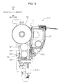
- FIG. 1 is a schematic cross-sectional view showing the inner structure of an image forming apparatus 1 according to the embodiment of the present disclosure.
- the image forming apparatus 1 is a tandem-type color printer and includes a substantially-rectangular main body housing 10. Note that the image forming apparatus may be a full-color or monochrome copier or complex machine.
- the main body housing 10 accommodates a plurality of process units that perform an image forming process on sheets.
- the image forming apparatus 1 has image forming units 2Y, 2C, 2M, and 2Bk, an optical scanning unit 23, an intermediate transfer unit 28, and a fixing unit 30 as the process units.
- the main body housing 10 has a sheet catching tray 11 at its top surface.
- a sheet ejection port 12 is opened facing the sheet catching tray 11.
- the main body housing 10 has an openable/closable manual feeding tray 13 at its side wall.
- the main body housing 10 has an attachable/detachable sheet feeding cassette 14, which accommodates sheets to be subjected to the image forming process, at its bottom part.
- the image forming units 2Y, 2C, 2M, and 2Bk are used to form toner images of the respective colors of yellow, cyan, magenta, and black based on image information sent from external equipment such as a computer and horizontally arranged in tandem at a predetermined interval.
- the respective image forming units 2Y, 2C, 2M, and 2Bk have cylindrical photosensitive drums 21 that is capable of holding electrostatic latent images formed on their peripheral surfaces and carrying toner images (developer images) on them, chargers 22 that charge the peripheral surfaces of the photosensitive drums 21, development units 24 that attach developer to electrostatic latent images to form toner images, toner containers 25Y, 25C, 25M, 25Bk that supply the toner of the respective colors of yellow, cyan, magenta, and black to the development units 24, primary transfer rollers 26 that primarily transfer toner images formed on the photosensitive drums 21, and cleaning units 27 that remove toner remaining on the peripheral surfaces of the photosensitive drums 21.
- the optical scanning unit 23 forms electrostatic latent images on the peripheral surfaces of the photosensitive drums 21 of the respective colors.
- the optical scanning unit 23 of the embodiment has a plurality of light sources for the respective colors and an image forming optical system that performs image forming and scanning on the peripheral surfaces of the photosensitive drums 21 of the respective colors with light emitted from the light sources.
- the intermediate transfer unit 28 primarily transfers toner images formed on the photosensitive drums 21.
- the intermediate transfer unit 28 has a transfer belt 281 that circulates around while contacting the peripheral surfaces of the respective photosensitive drums 21 and a driving roller 282 and a driven roller 283 around which the transfer belt 281 is stretched.
- the transfer belt 281 is pressed to the peripheral surfaces of the respective photosensitive drums 21 by the primary transfer roller 26.
- Toner images on the photosensitive drums 21 of the respective colors are primarily transferred onto the same spot on the transfer belt 281 to overlap each other. Thus, a full-color toner image is formed on the transfer belt 281.
- a secondary transfer roller 29 that forms a secondary transfer nip portion T via the transfer belt 281 is arranged facing the driving roller 282.
- a full-color toner image on the transfer belt 281 is secondarily transferred onto a sheet at the secondary transfer nip portion T.
- Toner remaining on the peripheral surface of the transfer belt 281 without being transferred onto a sheet is collected by a belt cleaning unit 284 arranged facing the driven roller 283.
- the fixing unit 30 has a fixing roller 31 including a heat source and a press roller 32 that forms a fixing nip portion N with the fixing roller 31.
- the fixing unit 30 performs a fixing process in which a sheet having a toner image transferred at the secondary transfer nip portion T is heated and pressed at a fixing nip portion N to weld toner to the sheet.
- a sheet having been subjected to the fixing process is ejected onto the sheet catching tray 11 via the sheet ejection port 12.
- the main body housing 10 has a sheet conveyance path for conveying sheets.
- the sheet conveyance path includes a main conveyance path P1 vertically extending from the vicinity of the bottom part to the vicinity of the top part of the main body housing 10 via the secondary transfer nip portion T and the fixing unit 30.
- the downstream end of the main conveyance path P1 is connected to the sheet ejection port 12.
- An inversion conveyance path P2 for conveying sheets in an inverted state at double-sided printing is extended from the most downstream end to the vicinity of the upstream end of the main conveyance path P1.
- a conveyance path P3 for manual feeding sheets ranging from the manual feeding tray 13 to the main conveyance path P1 is arranged over the sheet feeding cassette 14.
- the sheet feeding cassette 14 has a sheet accommodation portion that accommodates a batch of sheets.
- a pickup roller 151 that separately feeds out a sheet at the outermost layer of the batch of sheets and a pair of sheet feeding rollers 152 that feeds the sheet to the upstream end of the main conveyance path P1 are provided.
- Sheets placed on the manual feeding tray 13 are also fed to the upstream end of the main conveyance path P1 via the conveyance path P3 for manual feeding sheets.
- a pair of registration rollers 153 that feeds sheets to the transfer nip portion at a predetermined timing is arranged.
- the sheet When one-side printing (image forming) is performed on a sheet, the sheet is fed from the sheet feeding cassette 14 or the manual feeding tray 13 to the main conveyance path P1. Then, the sheet is subjected to a transfer process in which a toner image is transferred at the secondary transfer nip portion T and then subjected to a fixing process in which transferred toner is fixed onto the sheet by the fixing unit 30. After that, the sheet is ejected onto the sheet catching tray 11 via the sheet ejection port 12. On the other hand, when double-sided printing is performed on a sheet, one side of the sheet is subjected to the transfer process and the fixing process and then partially ejected onto the sheet catching tray 11 via the sheet ejection port 12.
- the sheet is switchback-conveyed and returned to the vicinity of the upstream end of the main conveyance path P1 via the inversion conveyance path P2. Subsequently, the other side of the sheet is subjected to the transfer process and the fixing process and ejected onto the sheet catching tray 11 via the sheet ejection port 12.
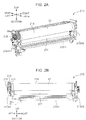
- FIG. 2A is a perspective view of a drum unit 210 according to the embodiment.
- FIG. 2B is a front view of the drum unit 210.
- FIG. 3 is an enlarged perspective view of the inside of the drum unit 210 according to the embodiment.
- a description will be given of the structure of one (the image forming unit 2Y) of the image forming units 2Y, 2C, 2M, and 2Bk, but the rest units also have the same structure.
- the image forming unit 2Y has the drum unit 210.
- the drum unit 210 has a box shape extending in a horizontal direction.
- the drum unit 210 is attachable/detachable to/from the main body housing 10.
- the photosensitive drum 21, the charger 22, and the cleaning unit 27 described above are integrally supported.
- the drum unit 210 has a unit housing 210H (housing).
- the unit housing 210H is a housing made of a resin material and supporting the photosensitive drum 21, the charger 22, and the cleaning unit 27 described above.
- the drum unit 210 has a substantially U-shape in a front view.
- the unit housing 210H has a unit left wall 210H1 and a unit right wall 210H2.
- Each of the unit left wall 210H1 and the unit right wall 210H2 is a wall portion provided to stand at an end in the horizontal direction of the unit housing 210H.
- the unit left wall 210H1 and the unit right wall 210H2 rotatably support the photosensitive drum 21.
- the photosensitive drum 21 has a drum sleeve 21A and drum flanges 21B.
- the main body housing 10 has a drum shaft 21G (first shaft portion) ( FIG. 3 ).
- the drum sleeve 21A has a cylindrical shape.
- On the outer peripheral surface of the drum sleeve 21A an electrostatic latent image is formed and a toner image is carried.
- the drum flanges 21B are members having a substantially cylindrical shape and attached at both ends in the axial direction (horizontal direction) of the drum sleeve 21A.
- the drum shaft 21G is a shaft extending in the horizontal direction inside the main body housing 10.
- the drum shaft 21G is inserted in the drum sleeve 21A via the drum flanges 21B. As a result, the position of the rotation shaft of the photosensitive drum 21 is determined, and the photosensitive drum 21 is rotatably supported about the drum shaft 21G.
- the cylinder of the drum flange 21B (driving transmission portion) on a left end side among the pair of drum flanges 21B has engagement portions 21C ( FIG. 3 ).
- a coupling gear (not shown) provided on the side of the main body housing 10 engages with the engagement portions 21C of the drum flanges 21B.
- the coupling gear is connected to a motor (driving portion) (not shown). As a result, the rotation driving force of the motor is transmitted to the photosensitive drum 21 via the coupling gear and the engagement portions 21C to rotate the photosensitive drum 21.
- the drum unit 210 also has drum bearing portions (not shown).
- the drum bearing portions are bearings attached to the unit left wall 210H1 and the unit right wall 210H2 of the unit housing 210H.
- the drum flanges 21B of the photosensitive drum 21 are inserted in the drum bearing portions, the photosensitive drum 21 is rotatably supported by the unit housing 210H.
- the charger 22 described above has a charging roller 221, a brush roller 222, charging housings 223, and a roller spring 224.
- the charging roller 221 uniformly charges the peripheral surface of the photosensitive drum 21 at predetermined potential while rotating to follow the rotation of the photosensitive drum 21.
- the brush roller 222 is a roller member having a conductive brush formed in all directions about the shaft.
- the brush roller 222 has a brush shaft 222A (fourth shaft portion) ( FIG. 3 ) parallel to the drum shaft 21G. The brush roller 222 rotates about the brush shaft 222A and cleans up the surface of the charging roller 221.
- the pair of charging housings 223 is provided at both ends in the axial direction of the charging roller 221 and the brush roller 222.
- the charging housings 223 rotatably support the charging roller 221 and the brush roller 222 while maintaining a constant distance between the shafts of the charging roller 221 and the brush roller 222.
- the roller spring 224 is a spring member that presses the charging housing 223 to urge the charging roller 221 to the photosensitive drum 21.
- the cleaning unit 27 has a cleaning blade 271 (cleaning member) ( Figs. 1 and 3 ).
- the cleaning blade 271 is a plate-shaped elastic member that is supported by the unit housing 210H and contacts the peripheral surface of the photosensitive drum 21. The cleaning blade 271 cleans up the peripheral surface of the photosensitive drum 21.
- the drum unit 210 has a movement mechanism 200 ( FIG. 3 ).
- the movement mechanism 200 reciprocates the photosensitive drum 21 in the axial direction (horizontal direction) at a predetermined cycle.
- the movement mechanism 200 rotates the brush roller 222 and reciprocates the brush roller 222 in the axial direction at a predetermined cycle.
- the movement mechanism 200 has a drum driving gear 211 (first rotation gear), a drum thrust gear 212 (second rotation gear), a driving idle gear 225 (first intermediate gear), a thrust idle gear 226 (second intermediate gear), a brush driving gear 227 (third rotation gear), and a brush thrust gear 228 (fourth rotation gear).
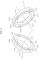
- FIG. 4 is a perspective view of the drum driving gear 211 and the drum thrust gear 212 according to the embodiment.
- the respective axis lines of the drum driving gear 211 and the drum thrust gear 212 cross each other in order to show mutually-facing side surfaces (a drum driving gear left side surface 211S and a drum thrust gear right side surface 212T).
- the drum driving gear 211 is a rotation gear fixed to the drum flange 21B of the photosensitive drum 21.
- the drum driving gear 211 has a spur gear with a predetermined number of teeth at its outer peripheral portion (driving gear outer peripheral portion 211H in FIG. 4 ).
- the drum driving gear 211 integrally rotates with the photosensitive drum 21 about the drum shaft 21G.
- the drum driving gear 211 has a pair of driving gear cam portions 211J ( FIG. 4 ).
- the driving gear cam portions 211J are cam portions formed at the drum driving gear left side surface 211S facing the drum thrust gear 212.
- the driving gear cam portions 211J are cam surfaces having different projection amounts toward the axial direction (toward the side of the drum thrust gear 212) along their circumferential direction in the rotation of the drum driving gear 211.
- the pair of driving gear cam portions 211J is formed to divide the inner peripheral side portion of the drum driving gear left side surface 211S into two in the circumferential direction.
- the driving gear cam portions 211J have first cam convex portions 211K and first cam concave portions 211L.
- the first cam convex portions 211K are portions having the highest projection height in the driving gear cam portions 211J.
- the first cam concave portions 211L are portions having the lowest projection height in the driving gear cam portions 211J.
- the pair of driving gear cam portions 211J has a continuous curved surface such that a movement amount (a change amount in their projection height) in the axial direction becomes constant per unit angle in the circumferential direction.
- the drum thrust gear 212 is arranged facing the drum driving gear 211 in the axial direction.
- the drum thrust gear 212 is a rotation gear fitted onto the outer peripheral portion of the drum flange 21B.
- the drum thrust gear 212 has a spur gear with teeth different in number from those of the drum driving gear 211 at its outer peripheral portion (thrust gear outer peripheral portion 212H in FIG. 4 ).
- a thrust gear left side surface 212S ( FIG. 3 ) of the drum thrust gear 212 contacts the drum bearing portion fitted in the unit left wall 210H1 to restrict in advance a position (position on the side of the left end) in the axial direction of the drum thrust gear 212.
- the drum thrust gear 212 does not move in the axial direction and rotates about the drum shaft 21G.
- the drum thrust gear 212 rotates with a predetermined speed difference (different rotation number) relative to the drum driving gear 211 as will be described later.
- the drum thrust gear 212 has a pair of thrust gear cam portions 212J ( FIG. 4
- the thrust gear cam portions 212J (second cam surfaces) are cam portions formed at the thrust gear right side surface 212T facing the drum driving gear 211.
- the thrust gear cam portions 212J are cam surfaces having different projection amounts toward the axial direction (toward the side of the drum driving gear 211) along their circumferential direction in the rotation of the drum thrust gear 212.
- the pair of thrust gear cam portions 212J is formed to divide the inner peripheral side portion of the thrust gear right side surface 212T into two in the circumferential direction.
- the thrust gear cam portions 212J have second cam convex portions 212K and second cam concave portions 212L.
- the first cam convex portions 212K are portions having the greatest projection height in the thrust gear cam portions 212J.
- the second cam concave portions 212L are portions having the lowest projection height in the thrust gear cam portions 212J.
- the pair of thrust gear cam portions 212J also has a continuous curved surface such that a movement amount in the axial direction becomes constant per unit angle in the circumferential direction.
- the driving idle gear 225 (first intermediate gear) and the thrust idle gear 226 (second intermediate gear) are a pair of rotation gears rotatable about their shaft parallel to the drum shaft 21G of the photosensitive drum 21.
- the driving idle gear 225 and the thrust idle gear 226 rotate about an idler shaft portion 221A ( FIG. 3 ) (second shaft portion) arranged on the same axis line as that of a rotation shaft 221S ( FIG.3 ) of the charging roller 221.
- the charging roller 221 rotates to follow the rotation of the photosensitive drum 21 as described above.
- the charging roller 221 has the rotation shaft 221S (third shaft portion) parallel to the drum shaft 21G.
- the both ends of the rotation shaft 221S is supported in the charging housings 223 ( FIG. 3 ) and do not extend to an outside in the axial direction from the charging housings 223.
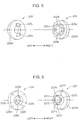
- FIG. 5 is a perspective view of the driving idle gear 225 and the thrust idle gear 226 according to the embodiment. Note that the driving idle gear 225 and the thrust idle gear 226 are tilted to show their mutually-facing side surfaces in FIG. 5 .
- the driving idle gear 225 engages with the gear teeth of the drum driving gear 211.
- the driving idle gear 225 has a spur gear with a predetermined number of teeth at its outer peripheral portion 225H.
- the driving idle gear 225 has a pair of projection portions 225J projecting from its side surface facing the thrust idle gear 226.
- the pair of projection portions 225J has an arch shape and is arranged to be point-symmetrical about the rotation supporting point of the driving idle gear 225. Further, a pair of engagement concave portions 225K is formed between the pair of projection portions 225J.
- the thrust idle gear 226 is arranged adjacent to the driving idle gear 225 in the axial direction.
- the thrust idle gear 226 engages with the gear teeth of the drum thrust gear 212.
- the thrust idle gear 226 has a spur gear with a predetermined number of teeth at a thrust idle gear outer peripheral portion 226H.
- the thrust idle gear 226 has teeth different in number from those of the driving idle gear 225.
- the thrust idle gear 226 has a pair of engagement projection portions 226J projecting from its side surface facing the driving idle gear 225. When the engagement projection portions 226J of the thrust idle gear 226 fit into the engagement concave portions 225K of the driving idle gear 225, the driving idle gear 225 and the thrust idle gear 226 are connected to each other. As a result, the driving idle gear 225 and the thrust idle gear 226 integrally rotate about the idler shaft portion 221A.
- the brush driving gear 227 and the brush thrust gear 228 are a pair of rotation gears arranged on the brush shaft 222A ( FIG. 3 ) of the brush roller 222.
- FIG. 6 is a perspective view of the brush driving gear 227 and the brush thrust gear 228 according to the embodiment. Note that the brush driving gear 227 and the brush thrust gear 228 are tilted to show their mutually-facing side surfaces in FIG. 6 .
- the brush driving gear 227 is a gear fixed to the brush shaft 222A ( FIG. 3 ) extending to penetrate the charging housing 223 ( FIG. 3 ) on the left side.
- the brush driving gear 227 integrally rotates with the brush roller 222.
- the brush driving gear 227 transmits a rotation driving force to the brush roller 222.
- the brush driving gear 227 engages with the driving idle gear 225.
- the brush driving gear 227 has a spur gear with a predetermined number of teeth at a brush driving gear outer peripheral portion 227H ( FIG. 6 ).
- the brush driving gear 227 has a cylindrical projection portion 227T projecting from its side surface facing the brush thrust gear 228.
- the cylindrical projection portion 227T has a pair of brush driving gear cam portions 227J (third cam surfaces) at its tip margin.
- the brush driving gear cam portions 227J are cam surfaces having different projection amounts toward the axial direction (toward the side of the brush thrust gear 228) along their circumferential direction in the rotation of the brush driving gear 227.
- the pair of brush driving gear cam portions 227J is formed to divide the tip end of the cylindrical projection portion 227T into two in the circumferential direction.
- the brush driving gear cam portions 227J have third convex portions 227K and third concave portions 227L.
- the third convex portions 227K are portions having the greatest projection height in the brush driving gear cam portions 227J.
- the third concave portions 227L are portions having the lowest projection height in the brush driving gear cam portions 227J.
- the pair of brush driving gear cam portions 227J also has a continuous curved surface such that a movement amount in the axial direction becomes constant per unit angle in the circumferential direction.
- the brush thrust gear 228 is arranged adjacent to the brush driving gear 227 in the axial direction.
- the brush thrust gear 228 engages with the thrust idle gear 226.
- the brush thrust gear 228 has a spur gear with teeth different in number from those of the brush driving gear 227 at a brush thrust gear outer peripheral portion 228H ( FIG. 6 ).
- the brush thrust gear 228 rotates with a speed difference (different rotation number) relative to the brush driving gear 227. Note that a position in the axial direction of the brush thrust gear 228 is restricted by the unit left wall 210H1 ( Figs. 2A and 2B ) of the drum unit 210. Thus, the brush thrust gear 228 does not move in the axial direction and rotates about the brush shaft 222A.
- the brush thrust gear 228 has a cylindrical inner peripheral portion 228T formed to be recessed in a cylindrical shape at its side surface facing the brush driving gear 227.
- the cylindrical inner peripheral portion 228T has a pair of brush thrust gear cam portions 228J (fourth cam surfaces) at its bottom.
- the brush thrust gear cam portions 228J are cam surfaces having different projection amounts toward the axial direction (toward the side of the brush driving gear 227) along their circumferential direction in the rotation of the brush thrust gear 228.
- the pair of brush thrust gear cam portions 228J is formed to divide the bottom of the cylindrical inner peripheral portion 228T into two in the circumferential direction.
- the brush thrust gear cam portions 228J have fourth convex portions 228K and fourth concave portions 228L. Note that FIG. 6 shows the pair of fourth convex portion 228K and fourth concave portion 228L.
- the fourth convex portions 228K are portions having the greatest projection height in the brush thrust gear cam portions 228J.
- the fourth concave portions 228L are portions having the lowest projection height in the brush thrust gear cam portions 228J.
- the pair of brush thrust gear cam portions 228J also has a continuous curved surface such that a movement amount in the axial direction becomes constant per unit angle in the circumferential direction.
- the drum driving gear 211 that integrally rotates with the photosensitive drum 21 transmits the rotation driving force to the driving idle gear 225.
- the thrust idle gear 226 integrally rotates with the driving idle gear 225.
- the driving idle gear 225 transmits the rotation driving force to the brush driving gear 227, whereby the brush roller 222 rotates about the brush shaft 222A. With the rotation of the brush roller 222, the peripheral surface of the charging roller 221 is cleaned up. Note that the charging roller 221 rotates to follow the rotation of the photosensitive drum 21 when contacting the peripheral surface of the photosensitive drum 21.
- the drum thrust gear 212 rotates with a slight speed difference relative to the drum driving gear 211.
- the brush thrust gear 228 rotates with a slight speed difference relative to the brush driving gear 227.
- the drum driving gear 211 and the drum thrust gear 212 rotate with a slight speed difference between them, the driving gear cam portions 211J and the thrust gear cam portions 212J engage with each other at a predetermined cycle. As described above, the position in the axial direction of the drum thrust gear 212 is previously restricted. Thus, in the engagement between the driving gear cam portions 211J and the thrust gear cam portions 212J, the drum thrust gear 212 presses the drum driving gear 211 and the photosensitive drum 21 rightward when the first cam convex portions 211K ( FIG. 4 ) contact the second cam convex portions 212K ( FIG. 4 ). Note that the photosensitive drum 21 is urged leftward by a press spring (not shown) contacting the drum flange 21B on a right end side.
- the photosensitive drum 21 moves closest to the side of the drum thrust gear 212 with the urging force of the press spring.
- the photosensitive drum 21 cyclically reciprocates in the axial direction with the cyclic pressing force of the drum thrust gear 212 and the urging force of the press spring.
- the photosensitive drum 21 is set to reciprocate with a stroke of 0.25 mm.
- the brush roller 222 integrally fixed to the brush driving gear 227 reciprocates in the axial direction at a predetermined cycle.
- the brush roller 222 also has an urging spring like the photosensitive drum 21.
- the brush tip of the brush roller 222 is prevented from unevenly contacting the charging roller 221, and foreign matter and aggregate of developer caught in the brush tip of the brush roller 222 is dropped off from the brush of the brush roller 222. Accordingly, the surface of the charging roller 221 is stably cleaned up.
- the embodiment shows an example in which the drum driving gear 211 has the spur gear with 36 teeth at its outer peripheral portion and the drum thrust gear 212 has the spur gear with 33 teeth at its outer peripheral portion.
- the driving idle gear 225 has the spur gear with 13 teeth at its outer peripheral portion
- the thrust idle gear 226 has the spur gear with 12 teeth at its outer peripheral portion.
- the brush driving gear 227 has the spur gear with 15 teeth at its outer peripheral portion
- the brush thrust gear 228 has the spur gear with 14 teeth at its outer peripheral portion.
- the drum thrust gear 212 rotates relative to the drum driving gear 211 based on a difference in the number of the teeth between the driving idle gear 225 and the thrust idle gear 226.
- the spur gears of the drum driving gear 211, the drum thrust gear 212, the driving idle gear 225, the thrust idle gear 226, the brush driving gear 227, and the brush thrust gear 228 are profile shifted gears such that they appropriately engage with each other based on a difference in the number of the teeth.
- the photosensitive drum 21 when a printing operation is performed on an A4LEF-size sheet, the photosensitive drum 21 rotates about three revolutions to form an image on this single sheet. Further, the photosensitive drum 21 makes one round trip in the axial direction while rotating 71.5 revolutions about the drum shaft 21G. In addition, the brush roller 222 performs one round trip in the axial direction while rotating 45.5 revolutions about the brush shaft 222A. As described above, the reciprocation of the photosensitive drum 21 is carried out at a long cycle. Therefore, compared with a case in which the photosensitive drum 21 reciprocates in the axial direction at a short cycle in a printing operation, the occurrence of an image shift is prevented.
- the photosensitive drum 21 reciprocates at a short cycle at which the photosensitive drum 21 makes about one round trip while rotating 15 revolutions.
- a position in the axial direction of the photosensitive drum 21 greatly differs between the first sheet and the fifth sheet. Therefore, an image shift is likely to be noticeable. Since the photosensitive drum 21 reciprocates at a long cycle as described above in the embodiment, the occurrence of such an image defect is prevented.
- the image forming units 2Y, 2C, 2M, and 2Bk of the respective colors having the configuration of the drum unit 210 are mounted, the occurrence of a color shift in a color image is prevented.
- the movement cycle of the photosensitive drum 21 that reciprocates when the driving gear cam portions 211J and the thrust gear cam portions 212J contact each other desirably differs from the movement cycle of the brush roller 222 that reciprocates when the brush driving gear cam portions 227J and the brush thrust gear cam portions 228J contact each other as described above.
- the movement in the axial direction of the charging roller 221 does not synchronize with the movement in the axial direction of the brush roller 222. Accordingly, with the reciprocation of the brush roller 222, a position at which the brush roller 222 contacts the charging roller 221 may be reliably changed.
- the driving idle gear 225 and the thrust idle gear 226 are set to have a different number of teeth and integrally rotate. As described above, with the difference in the number of the teeth between the driving idle gear 225 and the thrust idle gear 226, the number of the rotations of the drum driving gear 211 and the drum thrust gear 212 may be made different. As a result, a cycle at which the driving gear cam portions 211J and the thrust gear cam portions 212J contact each other is set to be long, whereby the photosensitive drum 21 is allowed to reciprocate at a long cycle.
- the brush roller 222 may rotate and reciprocate in the axial direction with the rotation driving force transmitted from the photosensitive drum 21. Further, based on the difference in the number of the teeth between the driving idle gear 225 and the thrust idle gear 226, the number of the rotations of the brush driving gear 227 and the brush thrust gear 228 may be made different. As a result, a cycle at which the brush driving gear cam portions 227J and the brush thrust gear cam portions 228J contact each other is set to be long, whereby the brush roller 222 is allowed to reciprocate at a long cycle.
- the driving idle gear 225 and the thrust idle gear 226 may be rotatably arranged based on the shaft position of the charging roller 221.
- the movement mechanism 200 that rotates and reciprocates the photosensitive drum 21 and the brush roller 222 is compactly arranged.
- the two driving gear cam portions 211J and the two thrust gear cam portions 212J are arranged along the rotation direction.
- a plurality of first cam convex portions 211K and a plurality of first cam concave portions 211L may be arranged at positions at which the drum driving gear 211 is evenly divided along the rotation direction.
- a plurality of second cam convex portions 212K and a plurality of second cam concave portions 212L may be arranged at positions at which the drum thrust gear 212 is evenly divided along the rotation direction so as to correspond in number to the first cam convex portions 211K and the first cam concave portions 211L, respectively.
- the number of the reciprocation times of the photosensitive drum 21 may be adjusted with the arrangement of the convex portions and the concave portions.
- a single cam portion 211J and a single thrust gear cam portion 212J may be arranged over the entire circumferential direction of the drum driving gear 211 and the drum thrust gear 212, respectively.
- Fig. 7A is a perspective view of a drum unit 510 according to the embodiment.
- Fig. 7B is a front view of the drum unit 510.
- Fig. 8 is an enlarged front view of a part (left end side) of the drum unit 510 in Fig. 7B .
- Fig. 7A is a perspective view of a drum unit 510 according to the embodiment.
- Fig. 7B is a front view of the drum unit 510.
- Fig. 8 is an enlarged front view of a part (left end side) of the drum unit 510 in Fig. 7B .
- Fig. 7A is a perspective view of a drum unit 510 according to the embodiment.
- Fig. 7B is a front view of the drum unit 510.
- Fig. 8 is an enlarged front view of a part (left end side) of the drum unit 510 in Fig. 7B .
- FIG. 9 is a cross-sectional view of the drum unit 510.
- Fig. 10 is a cross-sectional view showing the state of the inside of the drum unit 510 in Fig. 8 .
- a description will be given of the structure of one (image forming unit 2Y) of the image forming units 2Y, 2C, 2M, and 2Bk in Fig. 1 , but the rest units also have the same structure.
- the image forming unit 2Y has the drum unit 510.
- the drum unit 510 has a box shape extending in the horizontal direction.
- the drum unit 510 is attachable/detachable to/from the main body housing 10 in Fig. 1 .
- a charger 52 and a cleaning unit 57 besides the photosensitive drum 51 described above are integrally supported ( Fig. 9 ).
- the drum unit 510 has a unit housing 510H (housing).
- the unit housing 510H is a housing made of a resin material and supporting the photosensitive drum 51, the charger 52, and the cleaning unit 57 described above.
- the drum unit 510 has a substantially U-shape in a front view.
- the unit housing 510H has a unit left wall 510H1 and a unit right wall 510H2.
- Each of the unit left wall 510H1 and the unit right wall 510H2 is a wall portion provided to stand at an end in the horizontal direction of the unit housing 510H.
- the unit left wall 510H1 and the unit right wall 510H2 rotatably support the photosensitive drum 51.
- the photosensitive drum 51 has a drum sleeve 51A and drum flanges 51B.
- the main body housing 10 has a drum shaft 51G (shaft) ( Fig. 10 ).
- the drum sleeve 51A has a cylindrical shape.
- On the outer peripheral surface of the drum sleeve 51A an electrostatic latent image is formed and a toner image is carried.
- the drum flanges 51B are members having a substantially cylindrical shape and attached at both ends in the axial direction (horizontal direction) of the drum sleeve 51A.
- the drum shaft 51G is a shaft extending in the horizontal direction inside the main body housing 10. When the drum unit 510 is attached to the main body housing 10, the drum shaft 51G is inserted in the drum sleeve 51A via the drum flanges 51B. As a result, the position of the rotation shaft of the photosensitive drum 51 is determined.
- the cylinder of the drum flange 51B (driving transmission portion) on a left end side among the pair of the drum flanges 51B has engagement portions (not shown in figures).
- a coupling gear (not shown) provided in the main body housing 10 engages with the engagement portions of the drum flange 51B.
- the coupling gear is connected to a motor (driving portion) (not shown).
- the rotation driving force of the motor is transmitted to the photosensitive drum 51 via the coupling gear and the engagement portions to rotate the photosensitive drum 51 about the drum shaft 51G.
- the drum unit 510 also has a drum bearing 510H3 ( Fig. 10 ).
- the drum bearing 510H3 is a bearing attached to the unit left wall 510H1 of the unit housing 510H.
- the photosensitive drum 51 is rotatably supported about the drum shaft 51G by the unit housing 510H.
- the photosensitive drum 51 has the same bearing as the drum bearing 510H3 on its right end side.
- the charger 52 described above has a charging roller 521, a brush roller 522, charging housings 523, and a roller spring 524.
- the charging roller 521 uniformly charges the peripheral surface of the photosensitive drum 51 at predetermined potential while rotating to follow the rotation of the photosensitive drum 51.
- the brush roller 522 is a roller member having a conductive brush formed in all directions about the shaft. The brush roller 522 rotates and cleans up the surface of the charging roller 521.
- the pair of charging housings 523 is provided at both ends in the axial direction of the charging roller 521 and the brush roller 522.
- the charging housings 523 rotatably support the charging roller 521 and the brush roller 522 while maintaining a constant distance between the shafts of the charging roller 521 and the brush roller 522.
- the roller spring 524 is a spring member that presses the charging housing 523 to urge the charging roller 521 to the photosensitive drum 51.
- the cleaning unit 57 has a cleaning blade 571 (cleaning member).
- the cleaning blade 571 is a plate-shaped elastic member that is supported by the unit housing 510H and contacts the peripheral surface of the photosensitive drum 51. The cleaning blade 571 cleans up the peripheral surface of the photosensitive drum 51.
- the drum unit 510 has a movement mechanism 51T ( Fig. 10 ).
- the movement mechanism 51T reciprocates the photosensitive drum 51 in the axial direction (horizontal direction) at a predetermined cycle.
- the movement mechanism 51T rotates the brush roller 522 and reciprocates the brush roller 522 in the axial direction at a predetermined cycle.
- the movement mechanism 51T has a drum driving gear 511 (first cam member), a drum thrust gear 512 (second cam member), a driving idle gear 525, a thrust idle gear 526, a brush driving gear 527, and a brush thrust gear 528.
- the drum driving gear 511 is a rotation gear fixed to the drum flange 51B of the photosensitive drum 51.
- the drum driving gear 511 has a spur gear with a predetermined number of teeth at its outer peripheral portion (driving gear outer peripheral portion 511H in Fig. 11 ).
- the drum driving gear 511 integrally rotates with the photosensitive drum 51 about the drum shaft 51G.
- the drum driving gear 511 has driving gear cam portions 511J that will be described later.
- the driving gear cam portions 511J are cam portions formed facing the drum thrust gear 512.
- the drum thrust gear 512 is arranged facing the drum driving gear 511 in the axial direction.
- the drum thrust gear 512 is a rotation gear fitted onto the outer peripheral portion of the drum flange 51B.
- the drum thrust gear 512 has a spur gear with teeth different in number from those of the drum driving gear 511 at its outer peripheral portion (thrust gear outer peripheral portion 512H in Fig. 11 ). Note that a position in the axial direction (position on the left end side) of the drum thrust gear 512 is restricted by a drum bearing 510H3. Thus, the drum thrust gear 512 does not move in the axial direction and rotates about the drum shaft 51G.
- drum thrust gear 512 rotates with a predetermined speed difference (different rotation number) relative to the drum driving gear 511 as will be described later.
- drum thrust gear 512 has thrust gear cam portions 512J that will be described later.
- the thrust gear cam portions 512J are cam portions formed facing the drum driving gear 511.
- the driving idle gear 525 (third intermediate gear) and the thrust idle gear 526 (fourth intermediate gear) are a pair of rotation gears rotatable about a shaft parallel to the drum shaft 51G of the photosensitive drum 51.
- the rotation shaft of the driving idle gear 525 and the thrust idle gear 526 is arranged on the same axis line as the rotation shaft 221S ( FIG.3 ) of the charging roller 521.
- the driving idle gear 525 engages with the gear teeth of the drum driving gear 511.
- the thrust idle gear 526 is arranged adjacent to the driving idle gear 525 in the axial direction.
- the thrust idle gear 526 engages with the gear teeth of the drum thrust gear 512.
- the thrust idle gear 526 has teeth different in number from those of the driving idle gear 525.
- the driving idle gear 525 and the thrust idle gear 526 are connected to each other by an engagement claw (not shown). Thus, the driving idle gear 525 and the thrust idle gear 526 integrally rotate about the shaft.
- the brush driving gear 527 and the brush thrust gear 528 are a pair of rotation gears arranged on the rotation shaft of the brush roller 522 parallel to the drum shaft 51G.
- the brush driving gear 527 is integrated with the brush roller 522 and transmits a rotation driving force to the brush roller 522.
- the brush driving gear 527 engages with the driving idle gear 525.
- the brush thrust gear 528 is arranged adjacent to the brush driving gear 527 in the axial direction.
- the brush thrust gear 528 engages with the thrust idle gear 526.
- the brush thrust gear 528 has gear teeth different in number from those of the brush driving gear 527 and rotates with a speed difference (different rotation number) relative to the brush driving gear 527.
- the brush driving gear 527 has cam surfaces having different distances in the axial direction along its rotation direction to face the brush thrust gear 528.
- the brush thrust gear 528 has a cam follower capable of contacting the cam surfaces of the brush driving gear 527.
- the drum driving gear 511 that integrally rotates with the photosensitive drum 51 transmits the rotation driving force to the driving idle gear 525.
- the thrust idle gear 526 integrally rotates with the driving idle gear 525.
- the driving idle gear 525 transmits the rotation driving force to the brush driving gear 527, whereby the brush roller 522 rotates about the shaft. With the rotation of the brush roller 522, the peripheral surface of the charging roller 521 is cleaned up. Note that the charging roller 521 rotates to follow the rotation of the photosensitive drum 51 when contacting the peripheral surface of the photosensitive drum 51.
- the drum thrust gear 512 to which the rotation driving force is transmitted from the thrust idle gear 526 rotates with a slight speed difference relative to the drum driving gear 511.
- the brush thrust gear 528 to which the rotation driving force is transmitted from the thrust idle gear 526 rotates with a slight speed difference relative to the brush driving gear 527.
- the drum driving gear 511 and the drum thrust gear 512 rotate with a slight speed difference between them, the driving gear cam portions 511J and the thrust gear cam portions 512J engage with each other at a predetermined cycle.
- the position in the axial direction of the drum thrust gear 512 is restricted.
- the drum thrust gear 512 presses the drum driving gear 511 rightward at a predetermined cycle when the driving gear cam portions 511J and the thrust gear cam portions 512J engage with each other.
- the photosensitive drum 51 is urged leftward by a press spring (not shown) contacting the drum flange 51B on a right end side.
- the photosensitive drum 51 reciprocates in the axial direction with the cyclic pressing force of the drum thrust gear 512 and the urging force of the press spring.
- the brush roller 522 integrally fixed to the brush driving gear 527 reciprocates in the axial direction at a predetermined cycle.
- a position at which the brush roller 522 contacts the charging roller 521 moves in the axial direction.
- the brush tip of the brush roller 522 is prevented from unevenly contacting the charging roller 521, and foreign matter and aggregate of developer caught in the brush tip of the brush roller 522 is dropped off from the brush of the brush roller 522. Accordingly, the surface of the charging roller 521 is stably cleaned up.
- the embodiment shows an example in which the drum driving gear 511 has the spur gear with 36 teeth at its outer peripheral portion and the drum thrust gear 512 has the spur gear with 33 teeth at its outer peripheral portion.
- the driving idle gear 525 has the spur gear with 13 teeth at its outer peripheral portion
- the thrust idle gear 526 has the spur gear with 12 teeth at its outer peripheral portion.
- the brush driving gear 527 has the spur gear with 15 teeth at its outer peripheral portion
- the brush thrust gear 528 has the spur gear with 14 teeth at its outer peripheral portion.
- the drum thrust gear 512 rotates relative to the drum driving gear 511 based on a difference in the number of the teeth between the driving idle gear 525 and the thrust idle gear 526.
- the reciprocation of the photosensitive drum 51 is stably carried out.
- the spur gears of the drum driving gear 511, the drum thrust gear 512, the driving idle gear 525, the thrust idle gear 526, the brush driving gear 527, and the brush thrust gear 528 are profile shifted gears such that they appropriately engage with each other based on a difference in the number of the teeth.
- the photosensitive drum 51 makes one round trip in the axial direction while rotating 71.5 revolutions about the drum shaft 51G.
- the brush roller 522 makes one round trip in the axial direction while rotating 45.5 revolutions about the shaft.
- the reciprocation of the photosensitive drum 51 is carried out at a long cycle. Therefore, compared with a case in which the photosensitive drum 51 reciprocates at a short cycle in a printing operation, the occurrence of an image shift is prevented. That is, let it be assumed that the photosensitive drum 51 reciprocates at a short cycle at which the photosensitive drum 51 makes about one round trip while rotating 15 revolutions.
- the drum driving gear 511 and the drum thrust gear 512 have the driving gear cam portions 511J and the thrust gear cam portions 512J described above, respectively, in order to solve such a problem.
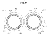
- Fig. 11 is a side view of the drum driving gear 511 and the drum thrust gear 512 according to the embodiment. Note that in the side view of Fig. 11 , the drum driving gear 511 is seen from its left side and the drum thrust gear 512 is seen from its right side. That is, in Fig. 11 , the mutually-facing surfaces of the drum driving gear 511 and the drum thrust gear 512 (a driving gear left side surface 511S of the drum driving gear 511 and a thrust gear right side surface 512T of the drum thrust gear 512) are shown facing upward in the figure.
- Fig. 12A is a perspective view of the drum thrust gear 512 according to the embodiment.
- Fig. 12B is an enlarged perspective view of a part of the drum thrust gear 512 in Fig. 12A .
- the outer peripheral portion 511H of the drum driving gear 511 and the thrust gear outer peripheral portion 512H of the drum thrust gear 512 each of which has a substantially ring shape, have gear teeth (not shown) different in number from each other.
- the drum driving gear 511 has the pair of driving gear cam portions 511J on the inner periphery side of the driving gear left side surface 511S.
- the drum thrust gear 512 also has the pair of thrust gear cam portions 512J on the inner periphery side of the thrust gear right side surface 512T.
- the pair of thrust gear cam portions 512J is formed to divide the inner peripheral side portion of the thrust gear right side surface 512T into two in the circumferential direction.
- the thrust gear cam portions 512J have second cam convex portions 512K (second convex portions), second cam concave portions 512L (second concave portions), and second inner-side convex portions 512M (second auxiliary convex portions).
- the driving gear cam portions 511J of the drum driving gear 511 have the same shape as that of the thrust gear cam portions 512J.
- the pair of driving gear cam portions 511J is formed to divide the inner peripheral side portion of the driving gear left side surface 511S into two in the circumferential direction.
- the driving gear cam portions 511J have first cam convex portions 511K (first convex portions) ( Fig. 13A ), first cam concave portions 511L (first concave portions) ( Fig. 13A ), and first inner-side convex portions 511M (first auxiliary convex portions) ( Fig. 13A ).
- first cam convex portions 511K first convex portions
- first cam concave portions 511L first concave portions
- first inner-side convex portions 511M first auxiliary convex portions
- the second cam convex portions 512K project at the consistent height toward the drum driving gear 511 and along the rotation direction (indicated by arrow D111 in Fig. 11 and arrow D121 in Fig. 12A ) about the drum shaft 51G ( Fig. 9 ) of the drum thrust gear 512. That is, surfaces including the ridge lines of the second cam convex portions 512K extending in the rotation direction are surfaces parallel to the thrust gear right side surface 512T. Further, the second cam convex portions 512K are spirally formed about the shaft such that the second cam convex portions 512K curve toward an outside in a radial direction as they extend in the rotation direction of the drum thrust gear 512.
- the ridge lines of the second cam convex portions 512K move in the radial direction as the drum thrust gear 512 rotates.
- one of the second cam convex portions 512K of the pair of thrust gear cam portions 512J starts at a convex-portion start point 512K1 and extends up to a convex-portion end point 512K2.
- the second cam concave portions 512L are arranged to be along the second cam convex portions 512K and deeper in the axial direction than the second cam convex portions 512K and spirally formed about the shaft. As shown in Fig. 12B , the second cam convex portions 512K and the second cam concave portions 512L adjacent to each other in the radial direction are continuously connected to each other by cam slant surfaces 512N. Note that each of the second cam convex portions 512K and the second cam concave portions 512L has an arc shape with a predetermined curvature when seen in a cross section crossing the rotation direction (see Fig. 13A ).
- the second inner-side convex portions 512M are arranged to sandwich the second cam concave portions 512L with the second cam convex portions 512K in the radial direction and spirally formed about the shaft.
- the second inner-side convex portions 512M are convex portions extending parallel to the second cam convex portions 512K on the inside in the radial direction of the second cam convex portions 512K.
- the first cam convex portions 511K on the side of the drum driving gear 511 also project at the consistent height toward the drum thrust gear 512 and along the rotation direction (indicated by arrow D112 in Fig. 11 ) about the drum shaft 51G ( Fig. 9 ) of the drum driving gear 511. That is, surfaces including the ridge lines of the first cam convex portions 511K extending in the rotation direction are surfaces parallel to the driving gear left side surface 511S. Further, the first cam convex portions 511K are spirally formed about the shaft such that the first cam convex portions 511K curve toward the outside in the radial direction as they extend in the rotation direction of the drum driving gear 511.
- first cam concave portions 511L are arranged to be along the first cam convex portions 511K and deeper in the axial direction than the first cam convex portions 511K and spirally formed about the shaft. Note that each of the first cam convex portions 511K and the first cam concave portions 511L also has an arc shape with a predetermined curvature when seen in a cross section crossing the rotation direction (see Fig. 13A ).
- first inner-side convex portions 511M ( Fig. 13A ) are arranged to sandwich the first cam concave portions 511L with the first cam convex portions 511K in the radial direction and spirally formed about the shaft.
- the first inner-side convex portions 511M are convex portions extending parallel to the first cam convex portions 511K on the inside in the radial direction of the first cam convex portions 511K.
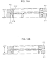
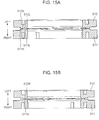
- FIGs. 13A to 15B are cross-sectional views showing the state of the engagement between the drum driving gear 511 and the drum thrust gear 512 according to the embodiment.
- Each of the figures corresponds to a cross-sectional view of the drum driving gear 511 and the drum thrust gear 512 seen in a cross section crossing the rotation direction, i.e., in a cross section including the axis line of each of the gears.
- Figs. 13A and 13B are views in which the same engagement state is seen at different positions in the rotation direction.
- Figs. 14A and 14B are views in which the same engagement state is seen at different positions in the rotation direction.
- Figs. 15A and 15B are views in which the same engagement state is seen at different positions in the rotation direction.
- the first cam convex portions 511K and the second cam convex portions 512K fit into the second cam concave portions 512L and the first cam concave portions 511L, respectively, as the drum driving gear 511 and the drum thrust gear 512 rotate.
- the photosensitive drum 51 fixed to the drum driving gear 511 is arranged at a position (second position) closest to the drum thrust gear 512 in the axial direction.
- the driving gear cam portions 511J and the thrust gear cam portions 512J are spirally formed. Therefore, as shown in Figs.
- the drum driving gear 511 and the drum thrust gear 512 are kept in contact with each other even at different positions in the rotation direction (circumferential direction).
- the convex portions and concave portions of the drum driving gear 511 and the drum thrust gear 512 continuously contact each other along the rotation direction.
- the falling (tilting in the axial direction) of the drum driving gear 511 and the drum thrust gear 512 is prevented.
- Figs. 14A and 14B show states in which the drum driving gear 511 and the drum thrust gear 512 rotate by a predetermined angle from the states shown in Figs. 13A and 13B . Due to a relative speed difference between the drum driving gear 511 and the drum thrust gear 512, a position at which the cam portions of the drum driving gear 511 and the drum thrust gear 512 contact each other shifts and the slant surface portions of the drum driving gear 511 and the drum thrust gear 512 (see the cam slant surfaces 512N in Fig. 12B ) contact each other. Even in this case, the drum driving gear 511 and the drum thrust gear 512 are kept in contact with each other at different positions in the rotation direction (circumferential direction) as shown in Figs. 14A and 14B . In other words, the slant surface portions continuously contact each other along the rotation direction.
- Figs. 15A and 15B show states in which the drum driving gear 511 and the drum thrust gear 512 rotate by a predetermined angle from the states shown in Figs. 14A and 14B .
- the first cam convex portions 511K are arranged to contact the second cam convex portions 512K
- the first cam concave portions 511L are arranged to face the second cam concave portions 512L.
- the photosensitive drum 51 is arranged at a position (first position) most separated from the drum thrust gear 512 in the axial direction.
- the drum driving gear 511 and the drum thrust gear 512 contact each other, the falling of the drum driving gear 511 and the drum thrust gear 512 is likely to occur.
- the drum driving gear 511 and the drum thrust gear 512 are kept in contact with each other even at different positions in the rotation direction (circumferential direction) as shown in Figs. 15A and 15B .
- the convex portions of the drum driving gear 511 and the drum thrust gear 512 continuously contact each other along the rotation direction.
- the falling of the drum driving gear 511 and the drum thrust gear 512 is prevented.
- the cam portions of the drum driving gear 511 and the drum thrust gear 512 may continuously contact each other at all times along the rotation direction. Accordingly, the falling of the drum driving gear 511 and the drum thrust gear 512 is prevented, and sudden movement in the axial direction of the photosensitive drum 51 is prevented. As a result, an image shift due to the sudden movement of the photosensitive drum 51 is prevented. Note that since each of the image forming units 2Y, 2C, 2M, and 2Bk has the configuration of the drum unit 510 described above, an image shift in each of the colors is prevented. As a result, the color shift of an image finally formed on a sheet is prevented.
- first cam convex portions 511K and the second cam concave portions 512L seem to have the same curvature and the second cam convex portions 512K and the first cam concave portions 511L seem to have the same curvature in Figs. 13A and 13B .
- the curvature of the first cam convex portions 511K is set to be greater than that of the second cam concave portions 512L, and the curvature of the second cam convex portions 512K is set to be greater than that of the first cam concave portions 511L.
- the first cam convex portions 511K or the second cam convex portions 512K are prevented from fitting into the second cam concave portions 512L or the first cam concave portions 511L without a gap.
- the drum driving gear 511 has the first inner-side convex portions 511M
- the drum thrust gear 512 has the second inner-side convex portions 512M.
- the drum driving gear 511 and the drum thrust gear 512 reliably engage with each other, whereby the rotation and reciprocation of the photosensitive drum 51 are reliably carried out.
Landscapes
- Physics & Mathematics (AREA)
- General Physics & Mathematics (AREA)
- Engineering & Computer Science (AREA)
- Computer Vision & Pattern Recognition (AREA)
- Electrophotography Configuration And Component (AREA)
- Electrostatic Charge, Transfer And Separation In Electrography (AREA)
Claims (4)
- Appareil de formation d'image comportant :un boîtier (10) ;un tambour photosensible (21) qui est supporté en rotation par le boîtier autour d'une première portion d'arbre (21G), une image latente électrostatique étant constituée sur une surface périphérique de celui-ci et une image de révélateur étant ainsi portée ;un élément de nettoyage (271) qui est supporté par le boîtier, entre en contact avec la surface périphérique du tambour photosensible et nettoie la surface périphérique ;une portion de transmission d'entraînement (21B) qui transmet une force d'entraînement, en rotation autour de la première portion d'arbre, au tambour photosensible ; etun mécanisme de déplacement (200) qui déplace le tambour photosensible en va-et-vient dans une direction axiale de la première portion d'arbre selon un cycle prédéfini, dans lequelle mécanisme de déplacement inclut :un premier engrenage de rotation (211) qui est fixé sur le tambour photosensible et tourne d'un seul tenant avec le tambour photosensible autour de la première portion d'arbre ;un deuxième engrenage de rotation (212) qui est disposé face au premier engrenage de rotation dans la direction axiale, a des dents dont le nombre diffère du nombre de dents du premier engrenage de rotation, est restreint dans une position de celui-ci dans la direction axiale et tourne autour de la première portion d'arbre avec une différence de vitesse prédéfinie par rapport au premier engrenage de rotation ; etune première paire d'engrenages de rotation pouvant tourner autour d'une deuxième portion d'arbre (221A) parallèle à la première portion d'arbre du tambour photosensible, la première paire d'engrenages de rotation incluantun premier engrenage intermédiaire (225) qui vient en prise avec le premier engrenage de rotation etun second engrenage intermédiaire (226) qui est disposé adjacent au premier engrenage intermédiaire dans la direction axiale, vient en prise avec le deuxième engrenage de rotation, a des dents dont le nombre diffère du nombre de dents du premier engrenage intermédiaire et tourne d'un seul tenant avec le premier engrenage intermédiaire,le premier engrenage de rotation (211) a une première surface de came (211J) qui est disposée au niveau d'une surface latérale de celui-ci face au deuxième engrenage de rotation et a différentes quantités de saillies dans la direction axiale le long d'une direction circonférentielle de celui-ci,le deuxième engrenage de rotation (212) a une deuxième surface de came (212J) qui est disposée au niveau d'une surface latérale de celui-ci face au premier engrenage de rotation, a différentes quantités de saillies dans la direction axiale le long d'une direction circonférentielle de celui-ci et est capable d'entrer en contact avec la première surface de came,le deuxième engrenage de rotation (212) tourne avec la différence de vitesse par rapport au premier engrenage de rotation, en conséquence de la transmission de la force d'entraînement en rotation, du premier engrenage de rotation au deuxième engrenage de rotation, par le biais du premier engrenage intermédiaire et du second engrenage intermédiaire lorsque le tambour photosensible tourne avec la force d'entraînement en rotation etle tambour photosensible se déplace en va-et-vient dans la direction axiale, en conséquence du contact entre la première surface de came et la deuxième surface de came, dans lequel l'appareil de formation d'image comporte en outreun rouleau de charge (221) qui a une troisième portion d'arbre (221S) parallèle à la première portion d'arbre, tourne autour de la troisième portion d'arbre, entre en contact avec la surface périphérique du tambour photosensible et charge la surface périphérique ; etun rouleau à brosse (222) qui a une quatrième portion d'arbre (222A) parallèle à la première portion d'arbre, tourne autour de la quatrième portion d'arbre et nettoie une surface du rouleau de charge, dans lequelle mécanisme de déplacement inclut en outre une seconde paire d'engrenages de rotation pouvant tourner autour de la quatrième portion d'arbre, la seconde paire d'engrenages de rotation incluant :un troisième engrenage de rotation (227) qui vient en prise avec le premier engrenage intermédiaire et tourne d'un seul tenant avec le rouleau à brosse etun quatrième engrenage de rotation (228) qui est disposé adjacent au troisième engrenage de rotation dans la direction axiale, a des dents dont le nombre diffère du nombre de dents du troisième engrenage de rotation, vient en prise avec le second engrenage intermédiaire, est restreint dans une position de celui-ci dans la direction axiale et tourne avec une différence de vitesse prédéfinie par rapport au troisième engrenage de rotation,le troisième engrenage de rotation (227) à une troisième surface de came (227J) qui est disposée au niveau d'une surface latérale de celui-ci face au quatrième engrenage de rotation et a des quantités de saillies différentes dans la direction axiale le long d'une direction circonférentielle de celui-ci,le quatrième engrenage de rotation (228) a une quatrième surface de came (228J) qui est disposée au niveau d'une surface latérale de celui-ci face au troisième engrenage de rotation, a différentes quantités de saillies dans la direction axiale le long d'une direction circonférentielle de celui-ci et peut entrer en contact avec la troisième surface de came,le rouleau à brosse tourne avec la transmission de la force d'entraînement en rotation, du premier engrenage intermédiaire au troisième engrenage de rotation, et le quatrième engrenage de rotation tourne avec la différence de vitesse par rapport au troisième engrenage de rotation en conséquence de la transmission de la force d'entraînement en rotation, du second engrenage intermédiaire au quatrième engrenage de rotation lorsque le tambour photosensible tourne avec la force d'entraînement en rotation etle rouleau à brosse se déplace en va-et-vient dans la direction axiale en conséquence d'un contact entre la troisième surface de came et la quatrième surface de came.
- Appareil de formation d'image selon la revendication 1, dans lequel
une pluralité des premières surfaces de came sont disposées au niveau de positions auxquelles le premier engrenage de rotation est divisé de manière égale le long de la direction circonférentielle et
une pluralité de deuxièmes surfaces de came, dont le nombre correspond aux premières surfaces de came, sont disposées au niveau de positions auxquelles le deuxième engrenage de rotation est divisé de manière égale le long de la direction circonférentielle. - Appareil de formation d'image selon la revendication 1 ou 2, dans lequel
la troisième portion d'arbre est disposée sur une même ligne d'axe qu'une ligne d'axe de la deuxième portion d'arbre. - Appareil de formation d'image selon la revendication 1, 2 ou 3, dans lequel
le rouleau de charge tourne en suivant la rotation du tambour photosensible et
un cycle de déplacement du tambour photosensible qui se déplace en va-et-vient, en conséquence du contact entre la première surface de came et la deuxième surface de came, diffère d'un cycle de déplacement du rouleau à brosse qui se déplace en va-et-vient en conséquence du contact entre la troisième surface de came et la quatrième surface de came.
Applications Claiming Priority (2)
| Application Number | Priority Date | Filing Date | Title |
|---|---|---|---|
| JP2015036085A JP5990610B2 (ja) | 2015-02-26 | 2015-02-26 | 画像形成装置 |
| JP2015036086A JP6035362B2 (ja) | 2015-02-26 | 2015-02-26 | 画像形成装置 |
Publications (2)
| Publication Number | Publication Date |
|---|---|
| EP3062155A1 EP3062155A1 (fr) | 2016-08-31 |
| EP3062155B1 true EP3062155B1 (fr) | 2018-10-17 |
Family
ID=55443042
Family Applications (1)
| Application Number | Title | Priority Date | Filing Date |
|---|---|---|---|
| EP16000436.2A Active EP3062155B1 (fr) | 2015-02-26 | 2016-02-23 | Appareil de formation d'image |
Country Status (3)
| Country | Link |
|---|---|
| US (1) | US9594338B2 (fr) |
| EP (1) | EP3062155B1 (fr) |
| CN (1) | CN105929649B (fr) |
Families Citing this family (7)
| Publication number | Priority date | Publication date | Assignee | Title |
|---|---|---|---|---|
| US9904230B2 (en) | 2016-05-31 | 2018-02-27 | Lexmark International, Inc. | Axially shifting a photoconductive drum using a cam |
| US9740157B1 (en) * | 2016-05-31 | 2017-08-22 | Lexmark International, Inc. | Axially shifting a photoconductive drum using a wear surface |
| US9857755B2 (en) | 2016-05-31 | 2018-01-02 | Lexmark International, Inc. | Axially shifting photoconductive drum |
| JP6729363B2 (ja) * | 2016-12-28 | 2020-07-22 | ブラザー工業株式会社 | 現像カートリッジ |
| JP6593353B2 (ja) | 2017-01-16 | 2019-10-23 | 京セラドキュメントソリューションズ株式会社 | 画像形成装置 |
| US11112749B1 (en) * | 2020-06-30 | 2021-09-07 | Jiangxi Yibo E-Tech Co. Ltd. | Process cartridge |
| CN116018562A (zh) * | 2020-09-10 | 2023-04-25 | 京瓷办公信息系统株式会社 | 显影装置以及具备该显影装置的图像形成装置 |
Family Cites Families (10)
| Publication number | Priority date | Publication date | Assignee | Title |
|---|---|---|---|---|
| JPS5817458A (ja) * | 1981-07-24 | 1983-02-01 | Canon Inc | 感光体駆動装置 |
| JPH0529475Y2 (fr) * | 1986-01-14 | 1993-07-28 | ||
| US5572293A (en) * | 1993-10-14 | 1996-11-05 | Ricoh Company, Ltd. | Method of and system for cleaning a charge inducing member |
| KR0140630B1 (ko) * | 1994-11-08 | 1998-07-15 | 김광호 | 화상 형성 장치의 브러시 접촉 대전 장치 |
| JP4330135B2 (ja) * | 2003-12-22 | 2009-09-16 | 京セラミタ株式会社 | 往復運動機構 |
| KR100653086B1 (ko) * | 2005-01-21 | 2006-12-01 | 삼성전자주식회사 | 폐토너 분쇄장치 및 이를 구비한 토너 카트리지 |
| JP2011133763A (ja) | 2009-12-25 | 2011-07-07 | Brother Industries Ltd | 現像カートリッジ |
| JP5323043B2 (ja) * | 2010-12-24 | 2013-10-23 | 京セラドキュメントソリューションズ株式会社 | 画像形成装置 |
| JP5753870B2 (ja) * | 2013-03-28 | 2015-07-22 | 京セラドキュメントソリューションズ株式会社 | カール矯正装置、およびこれを備えた画像形成装置 |
| JP2015025931A (ja) * | 2013-07-26 | 2015-02-05 | 京セラドキュメントソリューションズ株式会社 | 画像形成装置 |
-
2016
- 2016-02-23 EP EP16000436.2A patent/EP3062155B1/fr active Active
- 2016-02-24 CN CN201610101607.8A patent/CN105929649B/zh active Active
- 2016-02-24 US US15/051,774 patent/US9594338B2/en active Active
Non-Patent Citations (1)
| Title |
|---|
| None * |
Also Published As
| Publication number | Publication date |
|---|---|
| CN105929649A (zh) | 2016-09-07 |
| US9594338B2 (en) | 2017-03-14 |
| CN105929649B (zh) | 2018-11-30 |
| US20160252868A1 (en) | 2016-09-01 |
| EP3062155A1 (fr) | 2016-08-31 |
Similar Documents
| Publication | Publication Date | Title |
|---|---|---|
| US9594338B2 (en) | Image forming apparatus with photosensitive drum that cyclically reciprocates in an axial direction | |
| JP5323043B2 (ja) | 画像形成装置 | |
| US9632479B2 (en) | Process cartridge and image forming apparatus | |
| JP3676693B2 (ja) | ベルト搬送装置及び画像形成装置 | |
| US20240210875A1 (en) | Process cartridge and image forming apparatus | |
| JP5305008B2 (ja) | 現像装置、プロセスユニット及び画像形成装置 | |
| US9599951B2 (en) | Roller, image forming apparatus and manufacturing method of cylindrical shaft | |
| US8417173B2 (en) | Powder recovery device and image forming apparatus | |
| JP2010134047A (ja) | ベルトユニットおよび画像形成装置 | |
| US7558508B2 (en) | Image forming apparatus having belt wound around roller with specific roughness | |
| JP6035362B2 (ja) | 画像形成装置 | |
| JP5990610B2 (ja) | 画像形成装置 | |
| JP5167894B2 (ja) | 画像形成装置 | |
| JP6593353B2 (ja) | 画像形成装置 | |
| JP5439391B2 (ja) | 画像形成ユニット及びそれを備えた画像形成装置 | |
| US9285721B2 (en) | Transfer unit and image forming apparatus | |
| JP5800219B2 (ja) | 画像形成装置 | |
| JP4341601B2 (ja) | 画像形成装置 | |
| JP2006106465A (ja) | クリーニング装置とこれを備える画像形成装置 | |
| JP2006209024A (ja) | 定着装置 | |
| JP2015222315A (ja) | 画像形成装置及びプロセスカートリッジ | |
| JP2024015556A (ja) | 転写装置および画像形成装置 | |
| JP4257060B2 (ja) | 画像形成装置用多色現像装置の駆動伝達機構、画像形成装置 | |
| JP2006001670A (ja) | ベルト装置 | |
| JP2010014865A (ja) | 画像形成装置 |
Legal Events
| Date | Code | Title | Description |
|---|---|---|---|
| PUAI | Public reference made under article 153(3) epc to a published international application that has entered the european phase |
Free format text: ORIGINAL CODE: 0009012 |
|
| AK | Designated contracting states |
Kind code of ref document: A1 Designated state(s): AL AT BE BG CH CY CZ DE DK EE ES FI FR GB GR HR HU IE IS IT LI LT LU LV MC MK MT NL NO PL PT RO RS SE SI SK SM TR |
|
| AX | Request for extension of the european patent |
Extension state: BA ME |
|
| STAA | Information on the status of an ep patent application or granted ep patent |
Free format text: STATUS: REQUEST FOR EXAMINATION WAS MADE |
|
| 17P | Request for examination filed |
Effective date: 20170223 |
|
| RBV | Designated contracting states (corrected) |
Designated state(s): AL AT BE BG CH CY CZ DE DK EE ES FI FR GB GR HR HU IE IS IT LI LT LU LV MC MK MT NL NO PL PT RO RS SE SI SK SM TR |
|
| GRAP | Despatch of communication of intention to grant a patent |
Free format text: ORIGINAL CODE: EPIDOSNIGR1 |
|
| RIC1 | Information provided on ipc code assigned before grant |
Ipc: G03G 21/00 20060101ALI20180509BHEP Ipc: G03G 15/00 20060101AFI20180509BHEP |
|
| STAA | Information on the status of an ep patent application or granted ep patent |
Free format text: STATUS: GRANT OF PATENT IS INTENDED |
|
| INTG | Intention to grant announced |
Effective date: 20180614 |
|
| GRAS | Grant fee paid |
Free format text: ORIGINAL CODE: EPIDOSNIGR3 |
|
| GRAA | (expected) grant |
Free format text: ORIGINAL CODE: 0009210 |
|
| STAA | Information on the status of an ep patent application or granted ep patent |
Free format text: STATUS: THE PATENT HAS BEEN GRANTED |
|
| AK | Designated contracting states |
Kind code of ref document: B1 Designated state(s): AL AT BE BG CH CY CZ DE DK EE ES FI FR GB GR HR HU IE IS IT LI LT LU LV MC MK MT NL NO PL PT RO RS SE SI SK SM TR |
|
| REG | Reference to a national code |
Ref country code: GB Ref legal event code: FG4D |
|
| REG | Reference to a national code |
Ref country code: CH Ref legal event code: EP |
|
| REG | Reference to a national code |
Ref country code: IE Ref legal event code: FG4D |
|
| REG | Reference to a national code |
Ref country code: DE Ref legal event code: R096 Ref document number: 602016006332 Country of ref document: DE Ref country code: AT Ref legal event code: REF Ref document number: 1054730 Country of ref document: AT Kind code of ref document: T Effective date: 20181115 |
|
| REG | Reference to a national code |
Ref country code: NL Ref legal event code: MP Effective date: 20181017 |
|
| REG | Reference to a national code |
Ref country code: LT Ref legal event code: MG4D |
|
| REG | Reference to a national code |
Ref country code: AT Ref legal event code: MK05 Ref document number: 1054730 Country of ref document: AT Kind code of ref document: T Effective date: 20181017 |
|
| PG25 | Lapsed in a contracting state [announced via postgrant information from national office to epo] |
Ref country code: NL Free format text: LAPSE BECAUSE OF FAILURE TO SUBMIT A TRANSLATION OF THE DESCRIPTION OR TO PAY THE FEE WITHIN THE PRESCRIBED TIME-LIMIT Effective date: 20181017 |
|
| PG25 | Lapsed in a contracting state [announced via postgrant information from national office to epo] |
Ref country code: FI Free format text: LAPSE BECAUSE OF FAILURE TO SUBMIT A TRANSLATION OF THE DESCRIPTION OR TO PAY THE FEE WITHIN THE PRESCRIBED TIME-LIMIT Effective date: 20181017 Ref country code: LV Free format text: LAPSE BECAUSE OF FAILURE TO SUBMIT A TRANSLATION OF THE DESCRIPTION OR TO PAY THE FEE WITHIN THE PRESCRIBED TIME-LIMIT Effective date: 20181017 Ref country code: LT Free format text: LAPSE BECAUSE OF FAILURE TO SUBMIT A TRANSLATION OF THE DESCRIPTION OR TO PAY THE FEE WITHIN THE PRESCRIBED TIME-LIMIT Effective date: 20181017 Ref country code: HR Free format text: LAPSE BECAUSE OF FAILURE TO SUBMIT A TRANSLATION OF THE DESCRIPTION OR TO PAY THE FEE WITHIN THE PRESCRIBED TIME-LIMIT Effective date: 20181017 Ref country code: NO Free format text: LAPSE BECAUSE OF FAILURE TO SUBMIT A TRANSLATION OF THE DESCRIPTION OR TO PAY THE FEE WITHIN THE PRESCRIBED TIME-LIMIT Effective date: 20190117 Ref country code: BG Free format text: LAPSE BECAUSE OF FAILURE TO SUBMIT A TRANSLATION OF THE DESCRIPTION OR TO PAY THE FEE WITHIN THE PRESCRIBED TIME-LIMIT Effective date: 20190117 Ref country code: AT Free format text: LAPSE BECAUSE OF FAILURE TO SUBMIT A TRANSLATION OF THE DESCRIPTION OR TO PAY THE FEE WITHIN THE PRESCRIBED TIME-LIMIT Effective date: 20181017 Ref country code: PL Free format text: LAPSE BECAUSE OF FAILURE TO SUBMIT A TRANSLATION OF THE DESCRIPTION OR TO PAY THE FEE WITHIN THE PRESCRIBED TIME-LIMIT Effective date: 20181017 Ref country code: IS Free format text: LAPSE BECAUSE OF FAILURE TO SUBMIT A TRANSLATION OF THE DESCRIPTION OR TO PAY THE FEE WITHIN THE PRESCRIBED TIME-LIMIT Effective date: 20190217 Ref country code: ES Free format text: LAPSE BECAUSE OF FAILURE TO SUBMIT A TRANSLATION OF THE DESCRIPTION OR TO PAY THE FEE WITHIN THE PRESCRIBED TIME-LIMIT Effective date: 20181017 |
|
| PG25 | Lapsed in a contracting state [announced via postgrant information from national office to epo] |
Ref country code: GR Free format text: LAPSE BECAUSE OF FAILURE TO SUBMIT A TRANSLATION OF THE DESCRIPTION OR TO PAY THE FEE WITHIN THE PRESCRIBED TIME-LIMIT Effective date: 20190118 Ref country code: PT Free format text: LAPSE BECAUSE OF FAILURE TO SUBMIT A TRANSLATION OF THE DESCRIPTION OR TO PAY THE FEE WITHIN THE PRESCRIBED TIME-LIMIT Effective date: 20190217 Ref country code: RS Free format text: LAPSE BECAUSE OF FAILURE TO SUBMIT A TRANSLATION OF THE DESCRIPTION OR TO PAY THE FEE WITHIN THE PRESCRIBED TIME-LIMIT Effective date: 20181017 Ref country code: SE Free format text: LAPSE BECAUSE OF FAILURE TO SUBMIT A TRANSLATION OF THE DESCRIPTION OR TO PAY THE FEE WITHIN THE PRESCRIBED TIME-LIMIT Effective date: 20181017 Ref country code: AL Free format text: LAPSE BECAUSE OF FAILURE TO SUBMIT A TRANSLATION OF THE DESCRIPTION OR TO PAY THE FEE WITHIN THE PRESCRIBED TIME-LIMIT Effective date: 20181017 |
|
| REG | Reference to a national code |
Ref country code: DE Ref legal event code: R097 Ref document number: 602016006332 Country of ref document: DE |
|
| PG25 | Lapsed in a contracting state [announced via postgrant information from national office to epo] |
Ref country code: IT Free format text: LAPSE BECAUSE OF FAILURE TO SUBMIT A TRANSLATION OF THE DESCRIPTION OR TO PAY THE FEE WITHIN THE PRESCRIBED TIME-LIMIT Effective date: 20181017 Ref country code: CZ Free format text: LAPSE BECAUSE OF FAILURE TO SUBMIT A TRANSLATION OF THE DESCRIPTION OR TO PAY THE FEE WITHIN THE PRESCRIBED TIME-LIMIT Effective date: 20181017 Ref country code: DK Free format text: LAPSE BECAUSE OF FAILURE TO SUBMIT A TRANSLATION OF THE DESCRIPTION OR TO PAY THE FEE WITHIN THE PRESCRIBED TIME-LIMIT Effective date: 20181017 |
|
| PLBE | No opposition filed within time limit |
Free format text: ORIGINAL CODE: 0009261 |
|
| STAA | Information on the status of an ep patent application or granted ep patent |
Free format text: STATUS: NO OPPOSITION FILED WITHIN TIME LIMIT |
|
| PG25 | Lapsed in a contracting state [announced via postgrant information from national office to epo] |
Ref country code: SM Free format text: LAPSE BECAUSE OF FAILURE TO SUBMIT A TRANSLATION OF THE DESCRIPTION OR TO PAY THE FEE WITHIN THE PRESCRIBED TIME-LIMIT Effective date: 20181017 Ref country code: EE Free format text: LAPSE BECAUSE OF FAILURE TO SUBMIT A TRANSLATION OF THE DESCRIPTION OR TO PAY THE FEE WITHIN THE PRESCRIBED TIME-LIMIT Effective date: 20181017 Ref country code: SK Free format text: LAPSE BECAUSE OF FAILURE TO SUBMIT A TRANSLATION OF THE DESCRIPTION OR TO PAY THE FEE WITHIN THE PRESCRIBED TIME-LIMIT Effective date: 20181017 Ref country code: RO Free format text: LAPSE BECAUSE OF FAILURE TO SUBMIT A TRANSLATION OF THE DESCRIPTION OR TO PAY THE FEE WITHIN THE PRESCRIBED TIME-LIMIT Effective date: 20181017 |
|
| 26N | No opposition filed |
Effective date: 20190718 |
|
| REG | Reference to a national code |
Ref country code: CH Ref legal event code: PL |
|
| PG25 | Lapsed in a contracting state [announced via postgrant information from national office to epo] |
Ref country code: SI Free format text: LAPSE BECAUSE OF FAILURE TO SUBMIT A TRANSLATION OF THE DESCRIPTION OR TO PAY THE FEE WITHIN THE PRESCRIBED TIME-LIMIT Effective date: 20181017 Ref country code: MC Free format text: LAPSE BECAUSE OF FAILURE TO SUBMIT A TRANSLATION OF THE DESCRIPTION OR TO PAY THE FEE WITHIN THE PRESCRIBED TIME-LIMIT Effective date: 20181017 Ref country code: LU Free format text: LAPSE BECAUSE OF NON-PAYMENT OF DUE FEES Effective date: 20190223 |
|
| REG | Reference to a national code |
Ref country code: BE Ref legal event code: MM Effective date: 20190228 |
|
| REG | Reference to a national code |
Ref country code: IE Ref legal event code: MM4A |
|
| PG25 | Lapsed in a contracting state [announced via postgrant information from national office to epo] |
Ref country code: LI Free format text: LAPSE BECAUSE OF NON-PAYMENT OF DUE FEES Effective date: 20190228 Ref country code: CH Free format text: LAPSE BECAUSE OF NON-PAYMENT OF DUE FEES Effective date: 20190228 |
|
| PG25 | Lapsed in a contracting state [announced via postgrant information from national office to epo] |
Ref country code: IE Free format text: LAPSE BECAUSE OF NON-PAYMENT OF DUE FEES Effective date: 20190223 |
|
| PG25 | Lapsed in a contracting state [announced via postgrant information from national office to epo] |
Ref country code: BE Free format text: LAPSE BECAUSE OF NON-PAYMENT OF DUE FEES Effective date: 20190228 |
|
| PG25 | Lapsed in a contracting state [announced via postgrant information from national office to epo] |
Ref country code: TR Free format text: LAPSE BECAUSE OF FAILURE TO SUBMIT A TRANSLATION OF THE DESCRIPTION OR TO PAY THE FEE WITHIN THE PRESCRIBED TIME-LIMIT Effective date: 20181017 |
|
| PG25 | Lapsed in a contracting state [announced via postgrant information from national office to epo] |
Ref country code: MT Free format text: LAPSE BECAUSE OF NON-PAYMENT OF DUE FEES Effective date: 20190223 |
|
| PG25 | Lapsed in a contracting state [announced via postgrant information from national office to epo] |
Ref country code: CY Free format text: LAPSE BECAUSE OF FAILURE TO SUBMIT A TRANSLATION OF THE DESCRIPTION OR TO PAY THE FEE WITHIN THE PRESCRIBED TIME-LIMIT Effective date: 20181017 |
|
| PG25 | Lapsed in a contracting state [announced via postgrant information from national office to epo] |
Ref country code: HU Free format text: LAPSE BECAUSE OF FAILURE TO SUBMIT A TRANSLATION OF THE DESCRIPTION OR TO PAY THE FEE WITHIN THE PRESCRIBED TIME-LIMIT; INVALID AB INITIO Effective date: 20160223 |
|
| PG25 | Lapsed in a contracting state [announced via postgrant information from national office to epo] |
Ref country code: MK Free format text: LAPSE BECAUSE OF FAILURE TO SUBMIT A TRANSLATION OF THE DESCRIPTION OR TO PAY THE FEE WITHIN THE PRESCRIBED TIME-LIMIT Effective date: 20181017 |
|
| P01 | Opt-out of the competence of the unified patent court (upc) registered |
Effective date: 20230420 |
|
| PGFP | Annual fee paid to national office [announced via postgrant information from national office to epo] |
Ref country code: GB Payment date: 20260121 Year of fee payment: 11 |
|
| PGFP | Annual fee paid to national office [announced via postgrant information from national office to epo] |
Ref country code: DE Payment date: 20260121 Year of fee payment: 11 |
|
| PGFP | Annual fee paid to national office [announced via postgrant information from national office to epo] |
Ref country code: FR Payment date: 20260121 Year of fee payment: 11 |