EP3063405B1 - Procédé d'amortissement d'oscillations de tour de turbine éolienne - Google Patents
Procédé d'amortissement d'oscillations de tour de turbine éolienne Download PDFInfo
- Publication number
- EP3063405B1 EP3063405B1 EP14789156.8A EP14789156A EP3063405B1 EP 3063405 B1 EP3063405 B1 EP 3063405B1 EP 14789156 A EP14789156 A EP 14789156A EP 3063405 B1 EP3063405 B1 EP 3063405B1
- Authority
- EP
- European Patent Office
- Prior art keywords
- tower
- bag
- wind turbine
- oscillations
- component
- Prior art date
- Legal status (The legal status is an assumption and is not a legal conclusion. Google has not performed a legal analysis and makes no representation as to the accuracy of the status listed.)
- Active
Links
Images




Classifications
-
- F—MECHANICAL ENGINEERING; LIGHTING; HEATING; WEAPONS; BLASTING
- F03—MACHINES OR ENGINES FOR LIQUIDS; WIND, SPRING, OR WEIGHT MOTORS; PRODUCING MECHANICAL POWER OR A REACTIVE PROPULSIVE THRUST, NOT OTHERWISE PROVIDED FOR
- F03D—WIND MOTORS
- F03D80/00—Details, components or accessories not provided for in groups F03D1/00 - F03D17/00
- F03D80/80—Arrangement of components within nacelles or towers
- F03D80/88—Arrangement of components within nacelles or towers of mechanical components
-
- E—FIXED CONSTRUCTIONS
- E04—BUILDING
- E04H—BUILDINGS OR LIKE STRUCTURES FOR PARTICULAR PURPOSES; SWIMMING OR SPLASH BATHS OR POOLS; MASTS; FENCING; TENTS OR CANOPIES, IN GENERAL
- E04H9/00—Buildings, groups of buildings or shelters adapted to withstand or provide protection against abnormal external influences, e.g. war-like action, earthquake or extreme climate
- E04H9/02—Buildings, groups of buildings or shelters adapted to withstand or provide protection against abnormal external influences, e.g. war-like action, earthquake or extreme climate withstanding earthquake or sinking of ground
- E04H9/021—Bearing, supporting or connecting constructions specially adapted for such buildings
- E04H9/0215—Bearing, supporting or connecting constructions specially adapted for such buildings involving active or passive dynamic mass damping systems
-
- F—MECHANICAL ENGINEERING; LIGHTING; HEATING; WEAPONS; BLASTING
- F03—MACHINES OR ENGINES FOR LIQUIDS; WIND, SPRING, OR WEIGHT MOTORS; PRODUCING MECHANICAL POWER OR A REACTIVE PROPULSIVE THRUST, NOT OTHERWISE PROVIDED FOR
- F03D—WIND MOTORS
- F03D13/00—Assembly, mounting or commissioning of wind motors; Arrangements specially adapted for transporting wind motor components
- F03D13/10—Assembly of wind motors; Arrangements for erecting wind motors
-
- F—MECHANICAL ENGINEERING; LIGHTING; HEATING; WEAPONS; BLASTING
- F03—MACHINES OR ENGINES FOR LIQUIDS; WIND, SPRING, OR WEIGHT MOTORS; PRODUCING MECHANICAL POWER OR A REACTIVE PROPULSIVE THRUST, NOT OTHERWISE PROVIDED FOR
- F03D—WIND MOTORS
- F03D7/00—Controlling wind motors
- F03D7/02—Controlling wind motors the wind motors having rotation axis substantially parallel to the air flow entering the rotor
- F03D7/0296—Controlling wind motors the wind motors having rotation axis substantially parallel to the air flow entering the rotor to prevent, counteract or reduce noise emissions
-
- F—MECHANICAL ENGINEERING; LIGHTING; HEATING; WEAPONS; BLASTING
- F03—MACHINES OR ENGINES FOR LIQUIDS; WIND, SPRING, OR WEIGHT MOTORS; PRODUCING MECHANICAL POWER OR A REACTIVE PROPULSIVE THRUST, NOT OTHERWISE PROVIDED FOR
- F03D—WIND MOTORS
- F03D80/00—Details, components or accessories not provided for in groups F03D1/00 - F03D17/00
-
- F—MECHANICAL ENGINEERING; LIGHTING; HEATING; WEAPONS; BLASTING
- F16—ENGINEERING ELEMENTS AND UNITS; GENERAL MEASURES FOR PRODUCING AND MAINTAINING EFFECTIVE FUNCTIONING OF MACHINES OR INSTALLATIONS; THERMAL INSULATION IN GENERAL
- F16F—SPRINGS; SHOCK-ABSORBERS; MEANS FOR DAMPING VIBRATION
- F16F7/00—Vibration-dampers; Shock-absorbers
- F16F7/10—Vibration-dampers; Shock-absorbers using inertia effect
-
- F—MECHANICAL ENGINEERING; LIGHTING; HEATING; WEAPONS; BLASTING
- F05—INDEXING SCHEMES RELATING TO ENGINES OR PUMPS IN VARIOUS SUBCLASSES OF CLASSES F01-F04
- F05B—INDEXING SCHEME RELATING TO WIND, SPRING, WEIGHT, INERTIA OR LIKE MOTORS, TO MACHINES OR ENGINES FOR LIQUIDS COVERED BY SUBCLASSES F03B, F03D AND F03G
- F05B2230/00—Manufacture
- F05B2230/60—Assembly methods
-
- F—MECHANICAL ENGINEERING; LIGHTING; HEATING; WEAPONS; BLASTING
- F05—INDEXING SCHEMES RELATING TO ENGINES OR PUMPS IN VARIOUS SUBCLASSES OF CLASSES F01-F04
- F05B—INDEXING SCHEME RELATING TO WIND, SPRING, WEIGHT, INERTIA OR LIKE MOTORS, TO MACHINES OR ENGINES FOR LIQUIDS COVERED BY SUBCLASSES F03B, F03D AND F03G
- F05B2240/00—Components
- F05B2240/90—Mounting on supporting structures or systems
- F05B2240/91—Mounting on supporting structures or systems on a stationary structure
- F05B2240/912—Mounting on supporting structures or systems on a stationary structure on a tower
-
- F—MECHANICAL ENGINEERING; LIGHTING; HEATING; WEAPONS; BLASTING
- F05—INDEXING SCHEMES RELATING TO ENGINES OR PUMPS IN VARIOUS SUBCLASSES OF CLASSES F01-F04
- F05B—INDEXING SCHEME RELATING TO WIND, SPRING, WEIGHT, INERTIA OR LIKE MOTORS, TO MACHINES OR ENGINES FOR LIQUIDS COVERED BY SUBCLASSES F03B, F03D AND F03G
- F05B2260/00—Function
- F05B2260/96—Preventing, counteracting or reducing vibration or noise
- F05B2260/964—Preventing, counteracting or reducing vibration or noise by damping means
-
- Y—GENERAL TAGGING OF NEW TECHNOLOGICAL DEVELOPMENTS; GENERAL TAGGING OF CROSS-SECTIONAL TECHNOLOGIES SPANNING OVER SEVERAL SECTIONS OF THE IPC; TECHNICAL SUBJECTS COVERED BY FORMER USPC CROSS-REFERENCE ART COLLECTIONS [XRACs] AND DIGESTS
- Y02—TECHNOLOGIES OR APPLICATIONS FOR MITIGATION OR ADAPTATION AGAINST CLIMATE CHANGE
- Y02E—REDUCTION OF GREENHOUSE GAS [GHG] EMISSIONS, RELATED TO ENERGY GENERATION, TRANSMISSION OR DISTRIBUTION
- Y02E10/00—Energy generation through renewable energy sources
- Y02E10/70—Wind energy
- Y02E10/72—Wind turbines with rotation axis in wind direction
-
- Y—GENERAL TAGGING OF NEW TECHNOLOGICAL DEVELOPMENTS; GENERAL TAGGING OF CROSS-SECTIONAL TECHNOLOGIES SPANNING OVER SEVERAL SECTIONS OF THE IPC; TECHNICAL SUBJECTS COVERED BY FORMER USPC CROSS-REFERENCE ART COLLECTIONS [XRACs] AND DIGESTS
- Y02—TECHNOLOGIES OR APPLICATIONS FOR MITIGATION OR ADAPTATION AGAINST CLIMATE CHANGE
- Y02E—REDUCTION OF GREENHOUSE GAS [GHG] EMISSIONS, RELATED TO ENERGY GENERATION, TRANSMISSION OR DISTRIBUTION
- Y02E10/00—Energy generation through renewable energy sources
- Y02E10/70—Wind energy
- Y02E10/728—Onshore wind turbines
-
- Y—GENERAL TAGGING OF NEW TECHNOLOGICAL DEVELOPMENTS; GENERAL TAGGING OF CROSS-SECTIONAL TECHNOLOGIES SPANNING OVER SEVERAL SECTIONS OF THE IPC; TECHNICAL SUBJECTS COVERED BY FORMER USPC CROSS-REFERENCE ART COLLECTIONS [XRACs] AND DIGESTS
- Y02—TECHNOLOGIES OR APPLICATIONS FOR MITIGATION OR ADAPTATION AGAINST CLIMATE CHANGE
- Y02P—CLIMATE CHANGE MITIGATION TECHNOLOGIES IN THE PRODUCTION OR PROCESSING OF GOODS
- Y02P70/00—Climate change mitigation technologies in the production process for final industrial or consumer products
- Y02P70/50—Manufacturing or production processes characterised by the final manufactured product
Definitions
- the present invention relates to wind turbines, and in particular to methods of damping oscillations in towers of wind turbines.
- a horizontal-axis wind turbine typically includes a tower, a nacelle supported by the tower, and a rotor mounted to the nacelle. Over time there has been a significant increase in the overall size of these machines and their components. This increase in size presents many challenges, both before and during operation.
- wind turbine towers are tall, slender structures typically comprised of cylindrical and/or conical sections.
- vortices are shed alternately from opposite sides of the tower. This gives rise to a fluctuating force acting substantially perpendicular to the wind direction.
- the fluctuating force can lead to large oscillations when the periodic frequency of the vortex shedding is similar to one of the natural frequencies of the tower.
- EP 1 008 747 A2 and WO 2014/040598 A1 each discloses a system for damping oscillations experienced by a wind turbine tower.
- the system comprises a mass suspended inside the tower through.
- the mass is connected to the tower by a rod.
- a method of damping oscillations in a wind turbine tower comprises connecting a bag of material (e.g., sand) or liquid to a tower component at a first lateral distance away from a tower wall.
- the bag is also suspended from the tower component by a first vertical distance.
- the height of the tower component is known such that the first vertical distance corresponds to a particular height within the tower.
- the first lateral distance, first vertical distance, and mass of the bag are such that the bag is configured to hit said tower wall during oscillations in said wind turbine tower, in order to damp said oscillations in said wind turbine tower.
- the sandbags are configured to act as a pendulum counteracting a fundamental mode of vibration of the tower.
- the invention also provides a method of installing a wind turbine comprising erecting a tower of the wind turbine and installing a damping system in the tower.
- the damping system is installed in the manner mentioned above. That is, by connecting a bag of material or liquid to a tower component at a first lateral distance from a tower wall and suspending the bag from the tower component by a vertical distance. Again the height of the tower component is known such that the vertical distance corresponds to a particular height within the tower.
- the method of installation further involves damping oscillations caused by vortices shed from the tower, wherein the first lateral distance, first vertical distance, and mass of the bag are such that the bag is configured to hit said tower wall during oscillations in said wind turbine tower, in order to damp said oscillations in said wind turbine tower.
- the sandbags are configured to act as a pendulum that counteracts a fundamental mode of vibration of the tower. Eventually one or more nacelle components are positioned on the tower thereby making the tower less susceptible to oscillations caused by vortex shedding. Before or after this step, the damping system is removed from the tower.
- the ratio between said first vertical distance and said first lateral distance is between 5 and 20, such as between 8 and 15 or between 10 and 12.
- the mass of said bag is between 20kg and 300kg, such as between 50kg and 200kg or between 75kg and 150kg.
- the first lateral distance, first vertical distance, and mass of the bag are such that the bag during oscillation will act as a pendulum counteracting a fundamental mode of vibration of the tower prior to hitting said wind turbine tower.
- said damping of oscillations is at least partly obtained by converting kinetic energy into heat energy through plastic deformation of said bag.
- the bag is connected to and suspended from the tower component with a chain, cable, or rope, and wherein suspending the bag comprises:
- the method further comprising:
- the bag is connected to and suspending from the tower component with a chain and via a ratchet wrench positioned on the chain, and further wherein adjusting the distance by which the bag is suspended comprises operating the ratchet wrench to move the bag along the chain.
- the method further comprising:
- installing the damping system comprises passing the bag through an open top end of the tower or through a door of the tower after the tower is erected.
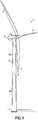
- Fig. 1 shows one example of a wind turbine 2 having a rotor 4 mounted to a nacelle 6, which is supported on a tower 8.
- the rotor 4 serves as the prime mover for an electromechanical system. Wind causes the rotor 4 to rotate, and this rotational energy is delivered to a power transmission system housed within the nacelle 6.
- the power transmission system converts the rotational energy into electrical power.
- the tower 8 shown in Fig. 1 is a tubular steel tower comprised of multiple tower sections 8a, 8b.
- the tower sections 8a, 8b are cylindrical or slightly tapered (i.e., conical) and stacked on top of each other. Again, however, this is merely an example.
- the description below focuses damping tower oscillations and may apply to any wind turbine tower that is a tall, slender structure susceptible to oscillations.
- the description may apply to steel towers having segmented tower sections, concrete towers, composite towers, hybrid towers (e.g., steel and concrete), wooden towers, etc.
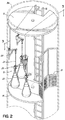
- a damping system 10 for the tower 8 is shown.
- the damping system 10 in this embodiment is installed in one of the tower sections (e.g., the uppermost tower section 8a).
- the tower section 8a includes various tower components, such as an upper platform 12, lower platform 14, and ladder 16 providing access to the upper and lower platforms 14, 16.
- the lower platform 14 is shaped to accommodate an elevator lift (not shown) and includes safety fencing 18 around the area for the elevator lift.
- the damping system 10 includes several sandbags 20 that are each suspended from a bracket 22 by a chain 24. More specifically, the sandbags 20 are each suspended from the hook of a ratchet wrench 26 (also referred to as a "ratchet chain hoist") positioned on the associated chain 24.
- the brackets 22 and sandbags 20 are distributed circumferentially about the tower section 8a in relation to a tower wall 28, as shown in Fig. 3 . Although three sandbags 20 are shown, any number of sandbags or even a single sandbag may be used in alternative embodiments. There may also be multiple sandbags suspended from the same bracket in alternative embodiments.
- the bracket 22 in this embodiment comprises a vertical support 30, horizontal support 32, and cross beam 34.
- the vertical support 30 may be mounted to a tower wall 28 using known techniques.
- the bracket 22 may be bolted or otherwise secured to magnets 34, which in turn are magnetically attached to the tower wall 28. Examples such magnets and techniques are described in WO 2003/067083 and WO 2004/099609 . Other known techniques include fastening, welding, adhesion, etc.
- a safety cable 36 or the like may connect the bracket 22 to another, permanently-installed tower component, such as the upper platform 12, thereby providing a back-up means of support in the event the bracket 22 slips along or disengages from the tower wall 28 due to ineffective mounting.
- the horizontal support 32 of the bracket 22 includes different attachment points 40 for the chain 24. This allows the sandbag 20 to be connected to the bracket 22 at different lateral distances from the tower wall 28.
- the vertical distance by which the sandbag 20 is suspended from the bracket 22 may be adjusted using the ratchet wrench 26.
- the lateral distance, vertical distance, and mass of each sandbag 20 are such that the sandbags 20 are configured to hit said tower wall 28, 56 during oscillations in said wind turbine tower, in order to damp said oscillations. It has been found that the most efficient damping is found when at least a small lateral distance is present between the sandbag and the wall, such that a small number of oscillations of the sandbag will occur prior to it hitting the wall.
- the sandbags are configured to act as pendulums that counteract a fundamental mode of vibration of the tower 8.
- the sandbags will start oscillating with a frequency corresponding to a fundamental mode of vibration of the tower for a few oscillations before taking out part of the kinetic energy in that oscillation by hitting the tower, thereby transforming the kinetic energy into heat energy through a plastic deformation of the sandbag.
- the damping system 10 has the advantage of being easy to install and remove, which provides a great amount of flexibility in terms of its use.
- the damping system 10 may be installed as a permanent fixture intended to remain in the tower 8 after the wind turbine 2 has been fully erected, or as a retrofit or temporary solution for addressing tower oscillations as they arise. The latter situation is particularly advantageous during the installation process of a wind turbine because of the challenges mentioned in the background section above.
- one method of installing the wind turbine 2 may involve using the damping system 10 during one or more stages of the installation.
- Such a method first comprises partially or completely erecting the tower 8.
- the damping system 10 may be installed in the uppermost tower section 8a before or after the tower section 8a is erected.
- the brackets 22 may be mounted to the tower wall 28 and the sandbags 20 connected to the brackets 22 prior to transporting the tower section 8a to the site of installation.
- These steps may alternatively occur after mounting the tower section 8a to the other previously-installed tower section 8b (or a foundation in embodiments where the tower 8 only comprises one tower section).
- the sandbags 20 are eventually suspended from the brackets 22 by an initial distance. This distance is adjusted by operating the ratchet wrench 26 until a desired vertical distance is attained.
- the desired vertical distance depends on the height of the tower 8, as does the desired lateral distance from the tower wall 28 (determined by the attachment point 40 of the chain 24 to the bracket 22).
- the lateral distance, vertical distance, and mass of each sandbag 20 are selected such that the sandbags 20 are configured to hit said tower wall 28, 56 during oscillations in said wind turbine tower, in order to damp said oscillations.
- the sandbags are configured to act as pendulums that counteract a fundamental mode of vibration of the tower 8. The method is particularly advantageous if the fundamental mode of vibration is the first natural frequency of bending vibration of the tower 8.
- This frequency is the most susceptible to oscillations caused by vortex shedding because of the lower wind speeds at which vortex shedding can be in resonance with the frequency.
- tuning the damping system 10 to the first natural frequency of bending vibration maximizes its effectiveness at damping oscillations caused by vortex shedding.
- the tower 8 may remain standing for an extended period of time prior to installing the nacelle 6 or its components, whose significant weight changes the dynamics of the overall structure and makes vortex shedding less of a concern.
- the logistics of installing a wind farm with several wind turbines may be optimized to make the most efficient use of resources and equipment (e.g., cranes).
- the damping system 10 is removed from the tower 8. This may be done after positioning one or more nacelle components (or even an entire nacelle with all nacelle components) on the tower 8. Alternatively, it may be done shortly before positioning the one or more nacelle components such that the tower 8 is only susceptible to oscillations caused by vortex shedding for a short period of time.
- One way in which the damping system 10 may be removed is by positioning the sandbags 20 onto the lower platform 14 (e.g., by using the ratchet wrenches 26). Each sandbag 20 is then moved from the lower platform 14 onto the elevator lift, transported toward the bottom of the tower 8 using the elevator lift, and eventually removed through a door near the bottom of the tower 8. It may be necessary to repeat these steps one or more times depending on the number of sandbags used and the capacity of the elevator lift.
- the damping system 10 may also be used earlier in the installation process, for example, when less than all of the tower sections have been erected. In that situation the damping system 10 is installed in the last tower section erected.
- the lateral distance and/or vertical distance of the sandbags 20 will be different from when the damping system 10 is used in the uppermost section of a completely-erected tower so that the damping system 10 is tuned to a natural frequency of the partially-erected tower.
- the different attachment points 40 on the brackets 22 and the ratchet wrenches 26 facilitate the ability to set these distances according to the dynamics of the structure.
- the partially-erected tower may remain standing for an extended period of time without concerns that vortex shedding will lead to significant oscillations.
- the damping system 10 may first be removed by passing the sandbags 20 through an open top end of the tower section in which they were installed. It is also possible to remove the damping system 10 in the manner described above using the elevator lift. Alternatively, if the damping system 10 is to be used in the next tower section, it may remain in the tower until the next tower section is installed and then moved accordingly. In other words, the damping system 10 may be removed from one tower section and installed in the next.
- Figs. 5-8 Various alternatives to the above-described embodiments are shown in Figs. 5-8 , where the same reference numbers are used to refer to corresponding structures.
- the brackets 22 in the above-described embodiments are merely representative tower components to which the sandbags 20 are connected via the ratchet wrenches 26 and chains 24. Other tower components may support the sandbags instead.
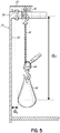
- Fig. 5 illustrates a sandbag 20 being connected to and suspended from a different type of bracket.
- the bracket shown is a beam 50 secured to a top flange 52 of a tower section 54 and extending inwardly away from a tower wall 56. Further, in fig.
- d L is the distance between the tower wall and the part of the bag closest to the tower wall
- dv is the distance between the point of contact for suspending the bag to a tower component fixed relative to to the tower wall and the center of gravity of the bag.
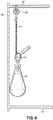
- Fig. 6 illustrates a sandbag 20 being connected to and suspended from a platform 60 (e.g., the upper platform 12 in Fig. 2 ). The connection occurs via the ratchet wrench 26 and chain 24, which is hooked onto or otherwise secured to an eye nut 62 that has been bolted to the platform 60.
- a platform 60 e.g., the upper platform 12 in Fig. 2
- the connection occurs via the ratchet wrench 26 and chain 24, which is hooked onto or otherwise secured to an eye nut 62 that has been bolted to the platform 60.
- fig. 6 illustrates how a sandbag can be mounted such that it abuts the wall when hanging freely without any oscillations of the tower.
- Fig. 7 illustrates a variation of the embodiment shown in Fig. 6 .
- the arrangement includes a frame 70 from which the chain 24 extends.
- the chain 24 may be engaged with one of several hooks 72 provided on the frame 70, which in turn is suspended from the eye nut 62 by a rope or cable 74.
- the rope 74 may be used like a sling and tied off to another tower component (not shown) after positioning the frame 70 at a desired height within the tower 8.
- the frame 70 offers the ability to suspend the sandbags at different vertical distances from the platform 60 without the need for a ratchet wrench or the like. However, ratchet wrenches may still be used if desired.
- FIG. 8 illustrates an alternative to the sandbags shown in other figures.
- a conventional bag 80 such as a tool bag, may be filled with more or less anything with a desired combined mass, such as a number of smaller sandbags 82 or other bags of liquid or material.
- the smaller bags 82 have the advantage of being easier to handle and transport compared to the sandbags 20 shown in Figs. 2-6 .
- the bag 80 is filled with a sufficient number of the smaller bags 82 to provide the desired mass.
- any bag of liquid or material may be used according to the invention.
- bag is meant in a broad sense to include any receptacle, container, or other structure that holds the liquid or material.
- sandbags are shown and described as being connected to the tower component(s) via ratchet wrenches and chains, it is also possible to use cables, ropes, or other devices.
- tower wall herein is meant in a broad sense to also include tower parts in connection with said tower wall, suitable for the purpose.
Landscapes
- Engineering & Computer Science (AREA)
- General Engineering & Computer Science (AREA)
- Mechanical Engineering (AREA)
- Chemical & Material Sciences (AREA)
- Life Sciences & Earth Sciences (AREA)
- Sustainable Development (AREA)
- Sustainable Energy (AREA)
- Combustion & Propulsion (AREA)
- Architecture (AREA)
- Environmental & Geological Engineering (AREA)
- Emergency Management (AREA)
- Business, Economics & Management (AREA)
- Civil Engineering (AREA)
- Structural Engineering (AREA)
- Wind Motors (AREA)
- Buildings Adapted To Withstand Abnormal External Influences (AREA)
Claims (19)
- Procédé d'amortissement d'oscillations dans un mât d'éolienne (8), comprenant :la suspension d'un sac (20, 80) de matériau ou de liquide à partir d'un élément de mât de sorte que le sac soit configuré pour frapper une paroi de mât (28, 56) dudit mât d'éolienne pendant des oscillations dans ledit mât d'éolienne, afin d'amortir lesdites oscillations dans ledit mât d'éolienne.
- Procédé selon la revendication 1, comprenant :la liaison d'un sac de matériau ou de liquide à un élément de mât à une première distance latérale (dL) d'éloignement d'une paroi de mât ;la suspension du sac à partir de l'élément de mât sur une première distance verticale (dV), dans lequel la hauteur de l'élément de mât est connue de sorte que la première distance verticale corresponde à une hauteur particulière à l'intérieur du mât, et dans lequel en outre la première distance latérale, la première distance verticale et la masse du sac sont telles que le sac est configuré pour frapper ladite paroi de mât pendant des oscillations dans ledit mât d'éolienne, afin d'amortir lesdites oscillations dans ledit mât d'éolienne.
- Procédé selon l'une quelconque des revendications précédentes, comprenant en outre :le montage d'une potence (22) sur le mât, la potence s'étendant en s'éloignant de la paroi de mât et servant d'élément de mât auquel le sac est relié.
- Procédé selon la revendication 3, dans lequel le montage de la potence sur le mât comprend la fixation des potences sur la paroi de mât sans soudage.
- Procédé selon les revendications 3 ou 4, dans lequel le montage de la potence sur le mât comprend la fixation de la potence sur une bride du mât.
- Procédé selon l'une quelconque des revendications précédentes, dans lequel le sac est relié et suspendu à partir d'une plateforme dans le mât.
- Procédé selon l'une quelconque des revendications précédentes, comprenant en outre :la fourniture d'une pluralité de sacs de matériau ou de liquide ; etla liaison et la suspension des sacs à un élément de mât commun ou à des éléments de mât respectifs de la manière prévue par l'une quelconque des revendications précédentes, dans lequel au moins une partie des sacs sont répartis de manière circonférentielle par rapport à la paroi de mât.
- Système d'amortissement d'oscillations subies par un mât d'éolienne (8), comprenant :un ou plusieurs sacs (20, 80) de matériau ou de liquide ;un ou plusieurs éléments de mât configurés pour être fixés sur le mât ; etun(e) ou plusieurs chaînes (24), câbles ou cordes (74) configuré(e)s pour suspendre les un ou plusieurs sacs à partir des un ou plusieurs éléments de mât, caractérisé en ce que ledit système est configuré de sorte que lors de son installation dans un mât d'éolienne, le sac soit configuré pour frapper une paroi de mât (28, 56) dudit mât d'éolienne pendant des oscillations dans ledit mât d'éolienne, afin d'amortir lesdites oscillations dans ledit mât d'éolienne.
- Système selon la revendication 8, dans lequel ledit sac est relié auxdits un ou plusieurs éléments de mât à une première distance latérale (dL) d'éloignement d'une paroi de mât ;
dans lequel ledit sac est suspendu à partir de l'élément de mât sur une première distance verticale (dV), dans lequel la hauteur de l'élément de mât est connue de sorte que la première distance verticale corresponde à une hauteur particulière à l'intérieur du mât, et dans lequel en outre la première distance latérale, la première distance verticale et la masse du sac sont telles que le sac est configuré pour frapper ladite paroi de mât pendant des oscillations dans ledit mât d'éolienne, afin d'amortir lesdites oscillations dans ledit mât d'éolienne. - Système selon la revendication 9, dans lequel le rapport entre ladite première distance verticale et ladite première distance latérale se situe entre 5 et 20, par exemple entre 8 et 15 ou entre 10 et 12.
- Système selon l'une quelconque des revendications 8 à 10, dans lequel la masse dudit sac se situe entre 20 kg et 300 kg, par exemple entre 50 kg et 200 kg ou entre 75 kg et 150 kg.
- Système selon l'une quelconque des revendications 9 à 11, dans lequel la première distance latérale, la première distance verticale et la masse du sac sont telles que le sac, pendant une oscillation, agira comme un pendule contrant un mode fondamental de vibration du mat avant de frapper ledit mât d'éolienne.
- Système selon l'une quelconque des revendications 8 à 12, dans lequel les un ou plusieurs éléments de mât présentent plusieurs points d'attache pour les chaînes, câbles ou cordes afin que les sacs puissent être positionnés à différentes distances latérales d'une paroi du mât d'éolienne.
- Système selon l'une quelconque des revendications 8 à 13, dans lequel chaque sac comprend au moins un grand sac rempli d'un certain nombre de sacs plus petits contenant le matériau ou liquide.
- Eolienne comprenant un système selon l'une quelconque des revendications 8 à 14.
- Procédé d'installation d'une éolienne (2), comprenant :l'érection d'un mât (8) de l'éolienne ;l'installation d'un système d'amortissement (10) selon l'une quelconque des revendications 8 à 14 dans le mât ;le positionnement d'un ou plusieurs éléments de nacelle sur le mât afin de rendre le mât moins sensible aux oscillations provoquées par le décollement de tourbillon ; etle retrait du système d'amortissement du mât avant le démarrage de l'éolienne.
- Procédé selon la revendication 16, dans lequel le mât comprend plusieurs sections de mât, et dans lequel en outre l'érection du mât comprend l'érection de moins de la totalité des sections de mât, le système d'amortissement étant utilisé pour amortir des oscillations du mât partiellement érigé, le procédé comprenant en outre :l'érection d'une autre section de mât pour continuer ou compléter l'érection du mât.
- Procédé selon la revendication 17, dans lequel les étapes d'installation et d'amortissement de la revendication 16 sont répétées après l'érection de l'autre section de mât, le sac étant relié à l'élément de mât à une seconde distance latérale et suspendu à partir d'un élément de mât sur une seconde distance verticale lorsque les étapes d'installation et d'amortissement sont répétées.
- Procédé selon l'une quelconque des revendications 16 à 18, dans lequel l'installation du système d'amortissement comprend en outre :l'installation de l'élément de mât dans une section de mât avant que la section de mât ne soit érigée en tant que partie du mât.
Applications Claiming Priority (2)
| Application Number | Priority Date | Filing Date | Title |
|---|---|---|---|
| DKPA201370627A DK201370627A1 (en) | 2013-10-28 | 2013-10-28 | Method of damping wind turbine tower oscillations |
| PCT/DK2014/050340 WO2015062608A1 (fr) | 2013-10-28 | 2014-10-20 | Procédé d'amortissement d'oscillations de tour de turbine éolienne |
Publications (2)
| Publication Number | Publication Date |
|---|---|
| EP3063405A1 EP3063405A1 (fr) | 2016-09-07 |
| EP3063405B1 true EP3063405B1 (fr) | 2018-02-28 |
Family
ID=51794703
Family Applications (1)
| Application Number | Title | Priority Date | Filing Date |
|---|---|---|---|
| EP14789156.8A Active EP3063405B1 (fr) | 2013-10-28 | 2014-10-20 | Procédé d'amortissement d'oscillations de tour de turbine éolienne |
Country Status (6)
| Country | Link |
|---|---|
| US (1) | US9683556B2 (fr) |
| EP (1) | EP3063405B1 (fr) |
| CN (1) | CN105745439B (fr) |
| DK (1) | DK201370627A1 (fr) |
| ES (1) | ES2669431T3 (fr) |
| WO (1) | WO2015062608A1 (fr) |
Cited By (1)
| Publication number | Priority date | Publication date | Assignee | Title |
|---|---|---|---|---|
| EP4202221B1 (fr) * | 2021-12-22 | 2024-07-31 | Comercial Química Massó S.A. | Amortisseur pour éoliennes |
Families Citing this family (29)
| Publication number | Priority date | Publication date | Assignee | Title |
|---|---|---|---|---|
| DK201370627A1 (en) * | 2013-10-28 | 2015-05-11 | Vestas Wind Sys As | Method of damping wind turbine tower oscillations |
| DE102015013098A1 (de) * | 2015-10-12 | 2017-04-13 | Senvion Gmbh | Verfahren zum Einbau eines Pendeldämpfers in eine Windenergieanlage, Befüllungssystem und Windenergieanlage |
| CN105220791B (zh) * | 2015-11-18 | 2017-07-28 | 山东大学 | 多维双重可调式减振控制装置 |
| EP3269997B1 (fr) * | 2016-07-14 | 2020-01-01 | Siemens Gamesa Renewable Energy A/S | Amortisseur d'oscillations pour une structure |
| US11603678B2 (en) * | 2016-09-27 | 2023-03-14 | Vestas Wind Systems A/S | Tower vibration damper |
| EP3586000B1 (fr) * | 2017-02-21 | 2020-11-25 | Vestas Wind Systems A/S | Amortisseur de vibration de tour |
| CN107013418A (zh) * | 2017-05-02 | 2017-08-04 | 沈阳建筑大学 | 一种机械式抑制大型风力发电机组共振的装置 |
| EP3415786B1 (fr) * | 2017-06-13 | 2021-10-20 | GE Renewable Technologies Wind B.V. | Amortisseurs de masse accordés pour amortir un mouvement d'oscillation d'une structure |
| ES3057923T3 (en) * | 2017-08-29 | 2026-03-05 | Ge Renewable Tech Wind Bv | Arrangements and methods for damping oscillations in structures |
| CN111051694B (zh) * | 2017-09-04 | 2021-07-20 | 菱重维斯塔斯海上风力有限公司 | 塔架减振器 |
| DK3450752T3 (da) * | 2017-09-04 | 2020-08-10 | Siemens Gamesa Renewable Energy As | Vindmølle med en adgangsanordning til en nacelle |
| CN108443396A (zh) * | 2018-01-15 | 2018-08-24 | 广东工业大学 | 一种风机用tmd阻尼器减震装置及其安装方法 |
| CN108443084A (zh) * | 2018-05-22 | 2018-08-24 | 中国电建集团中南勘测设计研究院有限公司 | 一种减振机构、风机塔筒及风机塔筒的施工方法 |
| CN108843522B (zh) * | 2018-06-07 | 2019-07-26 | 北京金风科创风电设备有限公司 | 阻尼器限位装置、塔筒及风力发电机组 |
| CN112352100A (zh) * | 2018-06-29 | 2021-02-09 | 菱重维斯塔斯海上风力有限公司 | 塔架阻尼器 |
| CN112368478B (zh) | 2018-06-29 | 2023-08-29 | 维斯塔斯风力系统有限公司 | 架设风力涡轮机的方法 |
| EP3814628B1 (fr) | 2018-06-29 | 2023-08-02 | Vestas Wind Systems A/S | Unité d'amortissement pour structure de tour |
| ES2739898A1 (es) | 2018-08-03 | 2020-02-04 | Siemens Gamesa Renewable Energy Innovation & Technology SL | Sistema de torre de aerogenerador para modificación de la segunda frecuencia natural |
| WO2020074526A1 (fr) * | 2018-10-09 | 2020-04-16 | Alimak Group Management Ab | Tours comprenant un mât |
| EP3643595A1 (fr) * | 2018-10-23 | 2020-04-29 | Siemens Gamesa Renewable Energy A/S | Gyroscope de stabilisation de mouvements de turbine éolienne |
| EP3899258B1 (fr) * | 2018-12-20 | 2024-05-22 | Vestas Wind Systems A/S | Système d'amortisseur de tour modulaire |
| WO2020224740A1 (fr) * | 2019-05-06 | 2020-11-12 | Vestas Wind Systems A/S | Amortissement des vibrations d'une structure |
| EP3792488A1 (fr) * | 2019-09-11 | 2021-03-17 | Siemens Gamesa Renewable Energy A/S | Plateforme de travail modulaire et système doté d'une plateforme de travail modulaire et d'un accessoire pour amortisseur à masse accordée dans une éolienne |
| CN111350630B (zh) * | 2020-03-08 | 2021-06-04 | 北京工业大学 | 采用多维减振装置的多风轮多向集能式风力发电机塔 |
| DK4172495T3 (da) * | 2020-06-24 | 2024-06-24 | Fm Energie Gmbh & Co Kg | Reversibelt ophæng til en svingningsdæmper ved opstillingen og demonteringen af en vindmølle |
| EP4194690A1 (fr) * | 2021-12-10 | 2023-06-14 | Siemens Gamesa Renewable Energy A/S | Dispositif amortisseur |
| ES2955376A1 (es) * | 2022-04-26 | 2023-11-30 | Setga S L U | Dispositivo auxiliar para aumentar el amortiguamiento en mastiles ligeros |
| WO2024008254A1 (fr) * | 2022-07-08 | 2024-01-11 | Vestas Wind Systems A/S | Amortisseur de vibrations pour une éolienne, structure de tour dotée d'un amortisseur de vibrations et procédé d'amortissement de vibrations |
| EP4551810B1 (fr) * | 2022-07-08 | 2026-04-15 | Vestas Wind Systems A/S | Éoliennes dotées d'amortisseurs à mécanismes d'inclinaison et procédés d'amortissement de vibrations dans des éoliennes |
Family Cites Families (13)
| Publication number | Priority date | Publication date | Assignee | Title |
|---|---|---|---|---|
| DE19856500B4 (de) * | 1998-12-08 | 2005-12-08 | Franz Mitsch | Schwingungstilger |
| JP2003176774A (ja) * | 2001-12-10 | 2003-06-27 | Kyowa Engineering Consultants Co Ltd | 風力発電装置 |
| US7931438B2 (en) * | 2006-12-13 | 2011-04-26 | General Electric Company | Active tower damper |
| GB0716733D0 (en) * | 2007-08-30 | 2007-10-10 | Reactec Ltd | Tower |
| AU2008328829B2 (en) * | 2007-11-28 | 2013-08-22 | Vestas Wind Systems A/S | Method for damping oscillations in a wind turbine |
| KR20110077629A (ko) * | 2009-12-30 | 2011-07-07 | 재단법인 포항산업과학연구원 | 풍력 터빈 타워 |
| DE102010015160B4 (de) * | 2010-04-16 | 2012-02-23 | Wölfel Beratende Ingenieure GmbH & Co. KG | Turmschwingungsdämpfer für eine Windenergieanlage und Windenergieanlage |
| WO2012090259A1 (fr) * | 2010-12-27 | 2012-07-05 | 三菱重工業株式会社 | Dispositif de maîtrise des vibrations pour éolienne de génération d'électricité, et éolienne de génération d'électricité |
| WO2012144066A1 (fr) * | 2011-04-22 | 2012-10-26 | 三菱重工業株式会社 | Dispositif d'amortissement des vibrations, dispositif de turbine éolienne et procédé d'amortissement des vibrations |
| EP2895741A1 (fr) * | 2012-09-17 | 2015-07-22 | Vestas Wind Systems A/S | Procédé d'amortissement des oscillations de tour d'éolienne |
| CN102936926B (zh) * | 2012-10-29 | 2015-08-19 | 广东电网公司电力科学研究院 | 一种多维碰撞耗能质量摆阻尼器 |
| WO2014198277A1 (fr) * | 2013-06-11 | 2014-12-18 | Vestas Wind Systems A/S | Tour éolienne ayant un amortisseur |
| DK201370627A1 (en) * | 2013-10-28 | 2015-05-11 | Vestas Wind Sys As | Method of damping wind turbine tower oscillations |
-
2013
- 2013-10-28 DK DKPA201370627A patent/DK201370627A1/da not_active Application Discontinuation
-
2014
- 2014-10-20 ES ES14789156.8T patent/ES2669431T3/es active Active
- 2014-10-20 US US15/032,918 patent/US9683556B2/en active Active
- 2014-10-20 WO PCT/DK2014/050340 patent/WO2015062608A1/fr not_active Ceased
- 2014-10-20 EP EP14789156.8A patent/EP3063405B1/fr active Active
- 2014-10-20 CN CN201480059013.4A patent/CN105745439B/zh active Active
Cited By (1)
| Publication number | Priority date | Publication date | Assignee | Title |
|---|---|---|---|---|
| EP4202221B1 (fr) * | 2021-12-22 | 2024-07-31 | Comercial Química Massó S.A. | Amortisseur pour éoliennes |
Also Published As
| Publication number | Publication date |
|---|---|
| WO2015062608A1 (fr) | 2015-05-07 |
| CN105745439B (zh) | 2019-11-15 |
| ES2669431T3 (es) | 2018-05-25 |
| US20160252079A1 (en) | 2016-09-01 |
| US9683556B2 (en) | 2017-06-20 |
| DK201370627A1 (en) | 2015-05-11 |
| CN105745439A (zh) | 2016-07-06 |
| EP3063405A1 (fr) | 2016-09-07 |
Similar Documents
| Publication | Publication Date | Title |
|---|---|---|
| EP3063405B1 (fr) | Procédé d'amortissement d'oscillations de tour de turbine éolienne | |
| EP2895741A1 (fr) | Procédé d'amortissement des oscillations de tour d'éolienne | |
| US9896310B2 (en) | Load-handling means for a tower or a tower section of a wind turbine and method for erecting a wind turbine | |
| CN108700024B (zh) | 安装或者拆卸多转子风轮机的风轮机部件的方法 | |
| US11365714B2 (en) | Methods for mounting or dismounting a wind turbine component of a multirotor wind turbine | |
| US11603822B2 (en) | Method of erecting a wind turbine | |
| CN101484699A (zh) | 风轮机塔架及用于改变风轮机塔架的本征频率的控制系统和方法 | |
| KR102360544B1 (ko) | 풍력 터빈용 타워 세그먼트를 사전 조립 및/또는 운송 및/또는 조립하기 위한 플랜지 프레임 및 조립 세트, 및 방법 | |
| US11754050B2 (en) | Modular tower damper system | |
| WO2021121500A1 (fr) | Atténuation de chute de nacelle par un fil de tension | |
| US20250128918A1 (en) | Climbing crane for erecting a wind turbine and method for erecting a wind turbine with a climbing crane | |
| EP2659131A1 (fr) | Méthode et appareil de montage d'une centrale éolienne dans une structure base élevée | |
| KR20140005616A (ko) | 타워 지지 구조물 및 타워 지지 구조물 건조방법 |
Legal Events
| Date | Code | Title | Description |
|---|---|---|---|
| PUAI | Public reference made under article 153(3) epc to a published international application that has entered the european phase |
Free format text: ORIGINAL CODE: 0009012 |
|
| 17P | Request for examination filed |
Effective date: 20160519 |
|
| AK | Designated contracting states |
Kind code of ref document: A1 Designated state(s): AL AT BE BG CH CY CZ DE DK EE ES FI FR GB GR HR HU IE IS IT LI LT LU LV MC MK MT NL NO PL PT RO RS SE SI SK SM TR |
|
| AX | Request for extension of the european patent |
Extension state: BA ME |
|
| DAX | Request for extension of the european patent (deleted) | ||
| RIC1 | Information provided on ipc code assigned before grant |
Ipc: F03D 13/00 20160101AFI20170726BHEP Ipc: F03D 80/80 20160101ALI20170726BHEP |
|
| GRAP | Despatch of communication of intention to grant a patent |
Free format text: ORIGINAL CODE: EPIDOSNIGR1 |
|
| INTG | Intention to grant announced |
Effective date: 20170914 |
|
| GRAS | Grant fee paid |
Free format text: ORIGINAL CODE: EPIDOSNIGR3 |
|
| GRAA | (expected) grant |
Free format text: ORIGINAL CODE: 0009210 |
|
| AK | Designated contracting states |
Kind code of ref document: B1 Designated state(s): AL AT BE BG CH CY CZ DE DK EE ES FI FR GB GR HR HU IE IS IT LI LT LU LV MC MK MT NL NO PL PT RO RS SE SI SK SM TR |
|
| REG | Reference to a national code |
Ref country code: GB Ref legal event code: FG4D Ref country code: CH Ref legal event code: EP |
|
| REG | Reference to a national code |
Ref country code: AT Ref legal event code: REF Ref document number: 974461 Country of ref document: AT Kind code of ref document: T Effective date: 20180315 |
|
| REG | Reference to a national code |
Ref country code: IE Ref legal event code: FG4D |
|
| REG | Reference to a national code |
Ref country code: DE Ref legal event code: R096 Ref document number: 602014021703 Country of ref document: DE |
|
| REG | Reference to a national code |
Ref country code: ES Ref legal event code: FG2A Ref document number: 2669431 Country of ref document: ES Kind code of ref document: T3 Effective date: 20180525 |
|
| REG | Reference to a national code |
Ref country code: NL Ref legal event code: MP Effective date: 20180228 |
|
| REG | Reference to a national code |
Ref country code: LT Ref legal event code: MG4D |
|
| REG | Reference to a national code |
Ref country code: AT Ref legal event code: MK05 Ref document number: 974461 Country of ref document: AT Kind code of ref document: T Effective date: 20180228 |
|
| PG25 | Lapsed in a contracting state [announced via postgrant information from national office to epo] |
Ref country code: NL Free format text: LAPSE BECAUSE OF FAILURE TO SUBMIT A TRANSLATION OF THE DESCRIPTION OR TO PAY THE FEE WITHIN THE PRESCRIBED TIME-LIMIT Effective date: 20180228 Ref country code: LT Free format text: LAPSE BECAUSE OF FAILURE TO SUBMIT A TRANSLATION OF THE DESCRIPTION OR TO PAY THE FEE WITHIN THE PRESCRIBED TIME-LIMIT Effective date: 20180228 Ref country code: HR Free format text: LAPSE BECAUSE OF FAILURE TO SUBMIT A TRANSLATION OF THE DESCRIPTION OR TO PAY THE FEE WITHIN THE PRESCRIBED TIME-LIMIT Effective date: 20180228 Ref country code: NO Free format text: LAPSE BECAUSE OF FAILURE TO SUBMIT A TRANSLATION OF THE DESCRIPTION OR TO PAY THE FEE WITHIN THE PRESCRIBED TIME-LIMIT Effective date: 20180528 Ref country code: FI Free format text: LAPSE BECAUSE OF FAILURE TO SUBMIT A TRANSLATION OF THE DESCRIPTION OR TO PAY THE FEE WITHIN THE PRESCRIBED TIME-LIMIT Effective date: 20180228 Ref country code: CY Free format text: LAPSE BECAUSE OF FAILURE TO SUBMIT A TRANSLATION OF THE DESCRIPTION OR TO PAY THE FEE WITHIN THE PRESCRIBED TIME-LIMIT Effective date: 20180228 |
|
| PG25 | Lapsed in a contracting state [announced via postgrant information from national office to epo] |
Ref country code: SE Free format text: LAPSE BECAUSE OF FAILURE TO SUBMIT A TRANSLATION OF THE DESCRIPTION OR TO PAY THE FEE WITHIN THE PRESCRIBED TIME-LIMIT Effective date: 20180228 Ref country code: LV Free format text: LAPSE BECAUSE OF FAILURE TO SUBMIT A TRANSLATION OF THE DESCRIPTION OR TO PAY THE FEE WITHIN THE PRESCRIBED TIME-LIMIT Effective date: 20180228 Ref country code: GR Free format text: LAPSE BECAUSE OF FAILURE TO SUBMIT A TRANSLATION OF THE DESCRIPTION OR TO PAY THE FEE WITHIN THE PRESCRIBED TIME-LIMIT Effective date: 20180529 Ref country code: BG Free format text: LAPSE BECAUSE OF FAILURE TO SUBMIT A TRANSLATION OF THE DESCRIPTION OR TO PAY THE FEE WITHIN THE PRESCRIBED TIME-LIMIT Effective date: 20180528 Ref country code: RS Free format text: LAPSE BECAUSE OF FAILURE TO SUBMIT A TRANSLATION OF THE DESCRIPTION OR TO PAY THE FEE WITHIN THE PRESCRIBED TIME-LIMIT Effective date: 20180228 Ref country code: AT Free format text: LAPSE BECAUSE OF FAILURE TO SUBMIT A TRANSLATION OF THE DESCRIPTION OR TO PAY THE FEE WITHIN THE PRESCRIBED TIME-LIMIT Effective date: 20180228 |
|
| REG | Reference to a national code |
Ref country code: FR Ref legal event code: PLFP Year of fee payment: 5 |
|
| PG25 | Lapsed in a contracting state [announced via postgrant information from national office to epo] |
Ref country code: IT Free format text: LAPSE BECAUSE OF FAILURE TO SUBMIT A TRANSLATION OF THE DESCRIPTION OR TO PAY THE FEE WITHIN THE PRESCRIBED TIME-LIMIT Effective date: 20180228 Ref country code: RO Free format text: LAPSE BECAUSE OF FAILURE TO SUBMIT A TRANSLATION OF THE DESCRIPTION OR TO PAY THE FEE WITHIN THE PRESCRIBED TIME-LIMIT Effective date: 20180228 Ref country code: AL Free format text: LAPSE BECAUSE OF FAILURE TO SUBMIT A TRANSLATION OF THE DESCRIPTION OR TO PAY THE FEE WITHIN THE PRESCRIBED TIME-LIMIT Effective date: 20180228 Ref country code: PL Free format text: LAPSE BECAUSE OF FAILURE TO SUBMIT A TRANSLATION OF THE DESCRIPTION OR TO PAY THE FEE WITHIN THE PRESCRIBED TIME-LIMIT Effective date: 20180228 Ref country code: EE Free format text: LAPSE BECAUSE OF FAILURE TO SUBMIT A TRANSLATION OF THE DESCRIPTION OR TO PAY THE FEE WITHIN THE PRESCRIBED TIME-LIMIT Effective date: 20180228 |
|
| REG | Reference to a national code |
Ref country code: DE Ref legal event code: R097 Ref document number: 602014021703 Country of ref document: DE |
|
| PG25 | Lapsed in a contracting state [announced via postgrant information from national office to epo] |
Ref country code: SM Free format text: LAPSE BECAUSE OF FAILURE TO SUBMIT A TRANSLATION OF THE DESCRIPTION OR TO PAY THE FEE WITHIN THE PRESCRIBED TIME-LIMIT Effective date: 20180228 Ref country code: CZ Free format text: LAPSE BECAUSE OF FAILURE TO SUBMIT A TRANSLATION OF THE DESCRIPTION OR TO PAY THE FEE WITHIN THE PRESCRIBED TIME-LIMIT Effective date: 20180228 Ref country code: SK Free format text: LAPSE BECAUSE OF FAILURE TO SUBMIT A TRANSLATION OF THE DESCRIPTION OR TO PAY THE FEE WITHIN THE PRESCRIBED TIME-LIMIT Effective date: 20180228 Ref country code: DK Free format text: LAPSE BECAUSE OF FAILURE TO SUBMIT A TRANSLATION OF THE DESCRIPTION OR TO PAY THE FEE WITHIN THE PRESCRIBED TIME-LIMIT Effective date: 20180228 |
|
| PLBE | No opposition filed within time limit |
Free format text: ORIGINAL CODE: 0009261 |
|
| STAA | Information on the status of an ep patent application or granted ep patent |
Free format text: STATUS: NO OPPOSITION FILED WITHIN TIME LIMIT |
|
| 26N | No opposition filed |
Effective date: 20181129 |
|
| PG25 | Lapsed in a contracting state [announced via postgrant information from national office to epo] |
Ref country code: SI Free format text: LAPSE BECAUSE OF FAILURE TO SUBMIT A TRANSLATION OF THE DESCRIPTION OR TO PAY THE FEE WITHIN THE PRESCRIBED TIME-LIMIT Effective date: 20180228 |
|
| REG | Reference to a national code |
Ref country code: CH Ref legal event code: PL |
|
| REG | Reference to a national code |
Ref country code: BE Ref legal event code: MM Effective date: 20181031 |
|
| PG25 | Lapsed in a contracting state [announced via postgrant information from national office to epo] |
Ref country code: MC Free format text: LAPSE BECAUSE OF FAILURE TO SUBMIT A TRANSLATION OF THE DESCRIPTION OR TO PAY THE FEE WITHIN THE PRESCRIBED TIME-LIMIT Effective date: 20180228 Ref country code: LU Free format text: LAPSE BECAUSE OF NON-PAYMENT OF DUE FEES Effective date: 20181020 |
|
| REG | Reference to a national code |
Ref country code: IE Ref legal event code: MM4A |
|
| PG25 | Lapsed in a contracting state [announced via postgrant information from national office to epo] |
Ref country code: CH Free format text: LAPSE BECAUSE OF NON-PAYMENT OF DUE FEES Effective date: 20181031 Ref country code: LI Free format text: LAPSE BECAUSE OF NON-PAYMENT OF DUE FEES Effective date: 20181031 Ref country code: BE Free format text: LAPSE BECAUSE OF NON-PAYMENT OF DUE FEES Effective date: 20181031 |
|
| PG25 | Lapsed in a contracting state [announced via postgrant information from national office to epo] |
Ref country code: IE Free format text: LAPSE BECAUSE OF NON-PAYMENT OF DUE FEES Effective date: 20181020 |
|
| PG25 | Lapsed in a contracting state [announced via postgrant information from national office to epo] |
Ref country code: MT Free format text: LAPSE BECAUSE OF NON-PAYMENT OF DUE FEES Effective date: 20181020 |
|
| PG25 | Lapsed in a contracting state [announced via postgrant information from national office to epo] |
Ref country code: TR Free format text: LAPSE BECAUSE OF FAILURE TO SUBMIT A TRANSLATION OF THE DESCRIPTION OR TO PAY THE FEE WITHIN THE PRESCRIBED TIME-LIMIT Effective date: 20180228 |
|
| PG25 | Lapsed in a contracting state [announced via postgrant information from national office to epo] |
Ref country code: PT Free format text: LAPSE BECAUSE OF FAILURE TO SUBMIT A TRANSLATION OF THE DESCRIPTION OR TO PAY THE FEE WITHIN THE PRESCRIBED TIME-LIMIT Effective date: 20180228 |
|
| PG25 | Lapsed in a contracting state [announced via postgrant information from national office to epo] |
Ref country code: MK Free format text: LAPSE BECAUSE OF NON-PAYMENT OF DUE FEES Effective date: 20180228 Ref country code: HU Free format text: LAPSE BECAUSE OF FAILURE TO SUBMIT A TRANSLATION OF THE DESCRIPTION OR TO PAY THE FEE WITHIN THE PRESCRIBED TIME-LIMIT; INVALID AB INITIO Effective date: 20141020 |
|
| PG25 | Lapsed in a contracting state [announced via postgrant information from national office to epo] |
Ref country code: IS Free format text: LAPSE BECAUSE OF FAILURE TO SUBMIT A TRANSLATION OF THE DESCRIPTION OR TO PAY THE FEE WITHIN THE PRESCRIBED TIME-LIMIT Effective date: 20180628 |
|
| P01 | Opt-out of the competence of the unified patent court (upc) registered |
Effective date: 20230521 |
|
| PGFP | Annual fee paid to national office [announced via postgrant information from national office to epo] |
Ref country code: DE Payment date: 20251028 Year of fee payment: 12 |
|
| PGFP | Annual fee paid to national office [announced via postgrant information from national office to epo] |
Ref country code: GB Payment date: 20251023 Year of fee payment: 12 |
|
| PGFP | Annual fee paid to national office [announced via postgrant information from national office to epo] |
Ref country code: FR Payment date: 20251027 Year of fee payment: 12 |
|
| PGFP | Annual fee paid to national office [announced via postgrant information from national office to epo] |
Ref country code: ES Payment date: 20251118 Year of fee payment: 12 |