EP3063448B1 - Verfahren zum bereitstellen eines rohrtransitsystems - Google Patents
Verfahren zum bereitstellen eines rohrtransitsystems Download PDFInfo
- Publication number
- EP3063448B1 EP3063448B1 EP14786161.1A EP14786161A EP3063448B1 EP 3063448 B1 EP3063448 B1 EP 3063448B1 EP 14786161 A EP14786161 A EP 14786161A EP 3063448 B1 EP3063448 B1 EP 3063448B1
- Authority
- EP
- European Patent Office
- Prior art keywords
- conduit
- sealing device
- sealing
- pipe
- wall
- Prior art date
- Legal status (The legal status is an assumption and is not a legal conclusion. Google has not performed a legal analysis and makes no representation as to the accuracy of the status listed.)
- Active
Links
Images


Classifications
-
- F—MECHANICAL ENGINEERING; LIGHTING; HEATING; WEAPONS; BLASTING
- F16—ENGINEERING ELEMENTS AND UNITS; GENERAL MEASURES FOR PRODUCING AND MAINTAINING EFFECTIVE FUNCTIONING OF MACHINES OR INSTALLATIONS; THERMAL INSULATION IN GENERAL
- F16L—PIPES; JOINTS OR FITTINGS FOR PIPES; SUPPORTS FOR PIPES, CABLES OR PROTECTIVE TUBING; MEANS FOR THERMAL INSULATION IN GENERAL
- F16L5/00—Devices for use where pipes, cables or protective tubing pass through walls or partitions
- F16L5/02—Sealing
- F16L5/10—Sealing by using sealing rings or sleeves only
-
- F—MECHANICAL ENGINEERING; LIGHTING; HEATING; WEAPONS; BLASTING
- F16—ENGINEERING ELEMENTS AND UNITS; GENERAL MEASURES FOR PRODUCING AND MAINTAINING EFFECTIVE FUNCTIONING OF MACHINES OR INSTALLATIONS; THERMAL INSULATION IN GENERAL
- F16L—PIPES; JOINTS OR FITTINGS FOR PIPES; SUPPORTS FOR PIPES, CABLES OR PROTECTIVE TUBING; MEANS FOR THERMAL INSULATION IN GENERAL
- F16L5/00—Devices for use where pipes, cables or protective tubing pass through walls or partitions
- F16L5/02—Sealing
- F16L5/04—Sealing to form a firebreak device
-
- F—MECHANICAL ENGINEERING; LIGHTING; HEATING; WEAPONS; BLASTING
- F16—ENGINEERING ELEMENTS AND UNITS; GENERAL MEASURES FOR PRODUCING AND MAINTAINING EFFECTIVE FUNCTIONING OF MACHINES OR INSTALLATIONS; THERMAL INSULATION IN GENERAL
- F16L—PIPES; JOINTS OR FITTINGS FOR PIPES; SUPPORTS FOR PIPES, CABLES OR PROTECTIVE TUBING; MEANS FOR THERMAL INSULATION IN GENERAL
- F16L5/00—Devices for use where pipes, cables or protective tubing pass through walls or partitions
- F16L5/02—Sealing
- F16L5/14—Sealing for double-walled or multi-channel pipes
-
- H—ELECTRICITY
- H02—GENERATION; CONVERSION OR DISTRIBUTION OF ELECTRIC POWER
- H02G—INSTALLATION OF ELECTRIC CABLES OR LINES, OR OF COMBINED OPTICAL AND ELECTRIC CABLES OR LINES
- H02G3/00—Installations of electric cables or lines or protective tubing therefor in or on buildings, equivalent structures or vehicles
- H02G3/22—Installations of cables or lines through walls, floors or ceilings, e.g. into buildings
Definitions
- the invention is related to a method for providing a pipe transit system.
- a pipe may be used for transport of flowable media from one compartment to another compartment or for transport of these flowable media from one side of the construction to another side of the construction.
- Such pipes may also be used for transport of flowable media into a construction.
- Normally compartments are separated by partitions, such as floors, decks, walls, ceilings, etc.
- an opening is provided in the partition, usually in a shape of a tubular passage, also referred to as a conduit.
- the diameter of the pipe extending through the opening, such as a conduit is smaller than the diameter of the opening.
- the annular space surrounding the pipe in the conduit needs to be sealed off.
- the quality of that sealing is usually the subject of regulations which take into account the conditions to which the sealing may be exposed under normal circumstances and in the exceptional and unfortunate circumstances such as the occurrence of a nearby fire.
- Such a pipe transit system may also be used, for instance, for two pipes having mutually different diameters connected with each other so that the fluid can flow through both pipes.
- One of the pipes may, for instance, form a house service connection and have a smaller diameter than a pipe which forms the main line.
- Such pipes may be used, for instance, for transporting water, gas, oils, liquids, chemicals, etc.
- the space between the two pipes may also be sealed by a system to which the invention relates.
- the pipe Even though a pipe is more often used for transport of flowable media, it is for the pipes used in relation with the presently proposed invention, not at all excluded that the pipe also contains cables, for instance, for telephone, electricity, optical signals, etc.
- the system provided by the method to which the invention relates may be used for walls of buildings, particularly foundation walls and floors but also ceilings or roofs where, by whatever method, the conduit is positioned in the wall, floor, ceiling or roof.
- the system provided by the method to which the invention relates can be used in the construction and/or maintenance of ships and offshore installations.
- Sections in such constructions are usually formed by placing prefabricated partitions according to a predetermined plan, in the case of a vessel, in a dock of a shipyard.
- feed-through conduits can be provided in the partitions, for instance with the aid of a welding method. After feeding through a pipe through the conduit, a sealing needs to be put in a space between the inner wall of the conduit and the outer wall of the pipe, to complete the pipe transit system.
- Systems provided by the method to which the invention relates are meant to be watertight as well as fire-resistant.
- GB 2186442 describes a transit system for pipes.
- the system comprises a metal frame having an opening filled with lead-through blocks and blanking blocks.
- the lead-through blocks comprise two half blocks which together can form a block surrounding a pipe.
- the remaining space in the opening is filled up with blank blocks.
- the space between the inner wall of the conduit, in this case a metal frame, and the pipes extending through the conduit or metal frame is filled up with blocks.
- a stay plate is positioned between each layer of blocks. Pressure is then applied to the assembled blocks to compress the blocks around the pipe and to clamp them together, against the side walls of the frame and to the stay plate.
- the system comprises a compression and packer system.
- Pressure can be applied by a system that requires tightening of nuts or compression bolts.
- the forces needed for compression are very high and partly passed onto the ducted pipe, often non-hydrostatically.
- the system cannot distribute the load evenly throughout the stacking of the pipes.
- the ducted pipe will carry a part of the load and prevent an even distribution.
- the blocks which are "in the shade of the ducted pipe" and much less subjected to compression can easily be forced out.
- Another problem is the irreversible deformation of the rubber, which reduces the flexibility of the transit system which can be detrimental when a part of the system is suddenly exposed to a much higher pressure.
- a system comprising a conduit having an inner wall and a pipe extending through the conduit in an axial direction thereof, so that the conduit has a part that is occupied by the pipe.
- the system further comprises two sealing devices, one inserted in each end of the conduit.
- This system designed to provide for a dynamic response to a sudden pressure shock occurring at one end of the conduit, for instance a high pressure wave as the result of a sudden entering of water in a compartment, a tsunami, etc., functions well under the circumstances for which it had been designed.
- a further improvement making this system also easily meeting the "watertight after fire" requirement, is still desirable.
- the invention is defined in the appended claim 1. It provides a pipe transit system comprising a conduit having an inner wall and at least one pipe extending through the conduit in an axial direction thereof so that a conduit has a pipe-part that is occupied by the at least one pipe.
- the system further comprises a first and a second sealing device inserted in the conduit each for sealing between the inner wall of the conduit and the at least one pipe, so that the conduit also has a sealed part.
- a third sealing device for sealing between the inner wall of the conduit and the at least one pipe is positioned in the sealed-part between the first and second sealing device.
- Each of the sealing devices is a separate entity and is unconnected to any of the other respective sealing devices.
- An advantage of this pipe transit system provided by the method of the invention is that the third sealing device which is positioned between the first and second sealing device necessarily had to be put in the conduit before both of the first and second sealing device were positioned. This means that the part of the conduit which is occupied by this third sealing device, that ends up between the first and second sealing device, cannot be occupied by air. As a consequence thereof, the length of the conduit that contains air when one of the first and/or second sealing device is inserted is shorter as compared to a situation in which no third sealing device is present.
- the air that needs to be compressed when one of the first and/or second sealing devices is inserted will be compressed into a much smaller volume as compared to a situation in which no "in-between" sealing device had been inserted previously into the conduit.
- the resistance felt by the second and a first sealing device will, due to the smaller volume available for compression of the air, be relatively high, given that the pressure will rapidly reach a relatively high level. This will have triggered a workman inserting one of the other two sealing devices to release the pressurized air from the gap, for instance by wedging in a small screwdriver between the outside of the sealing device and the inner wall of the conduit or the inside of the sealing device and the outside of the pipe, for release of the pressurized air, to then withdraw the screwdriver completely.
- the sealed-part has an axial length which corresponds to the length of the conduit.
- the widths of the air gaps are minimal, so that the advantages described above are optimal.
- Each air gap provides thermal insulation which is important. However, these gaps will not be at the expense of mechanical stability.
- the sum of the axial lengths of the first, the second and the third sealing device corresponds to the axial length of the conduit. Also here, the air gaps are minimal, so that the advantages as described above are optimal.
- At least one of the first and the second sealing device has a flange for hindering a full insertion of that sealing device into the conduit. Accordingly, that sealing device cannot be inserted any further when the end of the conduit abuts the flange.
- the length of the sealed-part as provided by that sealing device is well defined, allowing for selecting the appropriate length for the third sealing device that is positioned in-between the first and the second sealing device of which one is normally at each end of the sealed-part of the conduit.
- At least one of the sealing devices is free from metal parts for tightening and sealing.
- the sealing device provides sealing immediately after insertion into the conduit.
- At least one of the sealing devices comprises a vulcanized fire-resistant rubber plug.
- each of the sealing devices comprises a vulcanized fire-resistant rubber plug.
- these are already commercially available in many different dimensions.
- the material is endothermic in nature, so that it takes a long time before an increase in temperature becomes significant and changes properties of the material.
- the method further comprises:
- Each of the first, the second and the third sealing device is a separate entity and is unconnected to any of the other respective sealing devices.
- the method comprises inserting in the conduit the third sealing device before insertion both of the first and the second sealing device, ensuring that the above-described possibility is turned into reality.
- the method comprises inserting in the conduit one of the first or the second sealing device before inserting the third sealing device.
- all the sealing devices are inserted from one end of the conduit.
- the air pressure in the air gap between the third sealing device and the first or the second sealing device is allowed to drop down to atmospheric levels, for instance by wedging in a screwdriver between one of the inserted sealing devices and the inner wall of the conduit or the outer wall of the pipe.
- an increased air pressure in an air gap between inserted sealing devices is allowed to drop down to atmospheric levels, for instance by wedging in a screwdriver or a similar type of device, between the respective sealing device and the inner wall of the conduit and/or the outside of the pipe. After establishing an atmospheric pressure in the air gap, that screwdriver or similar device can be removed so that the complete sealing can be (re-)established.
- Fig 1 shows schematically in cross-section a first embodiment of a pipe transit system provided by a method according to the invention.
- the system comprises a conduit 1 which has an inner wall 2.
- the conduit is an integral part of a partition P.
- the conduit 1 can also be bolted or welded into an opening provided in partition P.
- the pipe 3 extends through the conduit 1 in an axial direction A. Accordingly, the conduit 1 has a pipe-part that is occupied by pipe 3.
- the system further comprises a first and a second sealing device I, II, inserted in the conduit 1. Each of these sealing devices I, II is for sealing between an inner wall 2 of the conduit 1 and the pipe 3, so that the conduit 1 also has a sealed-part.
- a third sealing device III is positioned also for sealing between the inner wall 2 of the conduit 1 and the pipe 3.
- Each of the first, the second and the third sealing device I, II, III is a separate entity.
- Each of the first, the second and the third sealing device, I, II, III is unconnected to any of the other respective sealing devices I, II, III. Small air gaps G are present between the sealing devices I, II, III.
- first and the second sealing device I, II each have a flange 4 for hindering a full insertion of that sealing device into the conduit 1.
- the third sealing device III is flangeless.
- at least one of the first, the second, and the third sealing device I, II, III is free from metal parts for tightening the sealing. Ideally, this applies to each of the first, the second, and the third sealing device I, II, III.
- at least one of the first, the second and the third sealing device I, II, III comprises a vulcanized fire-resistant rubber plug. More preferably, this applies to each of the first, the second, and the third sealing device I, II, III.
- first, the second, and the third sealing device I, II, III is provided with outer ribs 5 having tops spaced apart in longitudinal direction A for realizing, in use, annular contact surfaces which are each closed in itself in a circumferential direction between the sealing device I, II, III and the inner wall 2 of the conduit 1.
- at least one of the first, the second, and the third sealing device I, II, III is provided with inner ribs having tops spaced apart in a longitudinal direction for realizing, in use, annular contact surfaces which are closed in itself in a circumferential direction between the respective sealing device and the pipe 3.
- the vulcanized fire-resistant rubber is preferably of a silicon based rubber. It is possible that at least one of the first, the second, and the third sealing device I, II, III comprises at least two segmental parts.
- the sealing device I, II are preferably as described in WO 2004/111513 A1 .
- the outer ribs are more clearly shown.
- Plugs which are very useful as sealings in embodiments of the present invention are commercially available from the Applicant, as promoted under the trademark name "SLIPSIL" plugs.
- the mechanical stability is very good, providing good resistance to deformation.
- the air gaps G remain air gaps G. This also ensures that the thermal insulation provided by the air gaps remains intact.
- the third sealing device III is preferably also in the shape of a plug, for instance, as shown in WO 2008/023058 , particularly Figs. 2-10 .
- a plug elastically expand somewhat in transverse direction upon an axially applied pressure.
- this elastic expansion is only possible if the plug is not inserted in a conduit.
- the annular contact surfaces which extend in circumferential direction extend in axial direction. That is, the width of these annular contact surfaces will be enhanced, improving the sealing integrity. This will also further improve the mechanical stability without loss of the air gaps as the air cannot escape. This leads to an improved sealing.
- the number of third sealing devices III can be higher than one.
- the number of third sealing devices III depends on the length of the conduit 1, the length of the first and the second sealing device I, II and the length of the third sealing device III.
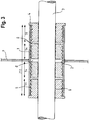
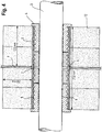
- Fig. 2 shows an embodiment in which two third sealing devices are positioned between the first and the second sealing device I, II.
- Fig. 3 shows that the air gaps G between the respective sealing devices I, II, II can be smaller, all depending on the length of the conduit and the length of the respective sealing devices.
- Fig. 4 shows a further reduction of the length of the air gaps G between the respective sealing devices I, II, III.
- the sealed-part has an axial length which corresponds to the length of the conduit 1.
- the air gaps G are minimal in terms of their width in axial direction.
- the sum of the axial lengths of the first, the second and the third sealing devices I, II, III corresponds to the axial length of the conduit 1.
- the axial width of the air gaps G is minimal.
- the mechanical stability is further improved when the air gaps G are smaller.
- the air gaps G remain a good insulation, also when the width (in axial direction) is small.
- conduit 1 is at each end thereof provided with a retainer 7 for retaining at that end one of the first and the second sealing devices I, II in the conduit 1.
- conduit 1 can be provided with a flange 8 to which the retainer 7 can be attached, for instance, by means of bolts and nuts.
- the retainer can only be applied after insertion of the first or the second sealing devices I, II.
- each of the sealing devices I, II, III is flangeless and preferably identical to any of the respective other sealing devices.
- the flangeless plugs are referred to as so-called "DYNATITE" plugs, also commercially available.
- these plugs are designed such that a sealing elastically expands in a transverse direction upon axially applied pressure. This results in annular contact surfaces which expand over a larger width, that is in axial direction, as compared with the situation without an axially applied pressure.
- the annular contact surfaces are present on the inside and the outside of the sealing device.
- the pipe transit system as proposed in this application is extremely suitable for a situation in which metal pipes extend through a conduit and "watertightness after fire" is required.
- Fig. 6 shows an embodiment of a pipe transit system provided by a method according to the invention in which the system comprises four sealing devices, namely the first and the second sealing device I, II and two third sealing devices III.
- Conduit 1 is provided with the retainer 7. Between retainer 7 and the second sealing device II a thermally expandable device 9 is positioned.
- conduit 1 is a so-called multi-part conduit having a main part 10 for holding each of the first, the second, and the third sealing devices I, II, III; and a sleeve-part 11 that is mountable to the main part 10 for holding the thermally expandable device 9.
- the sleeve-part 11 may comprise two shells which along an axial direction are mountable to each other. A transition from the sleeve-part 11 to the main part 10 is preferably free from diameter reducing structures.
- the thermally expandable device 9 may be a multi-part device 9.
- the device may also comprise layers which are concentrically oriented. It is also possible the device comprises a wrappable device, for instance a length of sheet which can be wrapped around pipe 3.
- the device may comprise ethylphenolacetate (EVA). Examples of a thermally expandable device that can be used in such an embodiment can be found in WO 2009/090247 A1 .
- the thermally expandable device 9 will expand, which it can only do in an axial direction A, in the direction of the sealing device I, II, III.
- These sealing devices will then experience an axially applied pressure, and tend to expand in a transverse direction. As explained above, this will result in annular contact surfaces which extend over a larger width, that is in axial direction, as compared with the situation without axially applied pressure. It follows that upon exposure to a nearby fire, the sealing device II and possible more will obtain a firmer grip on pipe 3 and the inner wall 2 of conduit 1. Subsequently, the watertightness after fire is very good.
- the embodiment shown in Fig. 6 is equally very suitable for a situation in which a weakenable pipe, for instance a plastic pipe, extends axially through the conduit 1.
- a weakenable pipe for instance a plastic pipe
- the other embodiments shown may be suitable for plastic pipes if, at least one of the first, the second, and the third sealing devices I, II, III comprises a rubberlike thermally expandable material having a component which causes the material upon exposure to heat to expand to an extent which is much more than the extent to which the material not having these components would expand.
- This component could be expandable graphite and/or intercalated graphite.
- the component causes expansion of the material at the softening temperature of LDPE and/or HDPE, then it is almost certain that the embodiment is suitable for each and every plastic pipe as softening temperatures of LDPE and/or HDPE are amongst the lowest for engineering plastic.
- each embodiment of a transit system according to the invention is preferably symmetrical, having an imaginary transverse cross-sectional plane of the conduit as the (mathematical) mirror plane. This plane may coincide with partition P.
- Conduit 1 is preferably made of metal or hard engineering plastic which is not thermally softenable.
- Fig. 7 shows an embodiment which is very similar to the embodiment shown in Fig. 6 .
- the conduit 1 is internally provided with blocking elements 13 for preventing further displacement of at least one entire first, second or third sealing device I, II, III in the conduit.
- the sealing devices II and III in the form of plugs as shown and between the blocking elements 13 and the thermally expandable device 9 will be axially compressed even further, as pressure is applied from one side by the expansion of the thermally expandable device and the plugs are kept at their position at the other side.
- the annular contact surfaces will enlarge in the axial direction, improving the sealing even further.
- Fig. 8 shows a test tube for testing the watertightness of embodiments of a pipe transit system provided by a method according to the invention, both before and after exposure to a fire.
- Water can enter the vessel V via tube T.
- the water pressure can be measured by a pressure gauge PG.
- Pipe-part PP is sealed off by a blind plug (not shown).
- the embodiment shown in Fig. 4 shows insulation material 12 applied against the outer wall of the conduit and extending by about 200 mm in radial direction. Insulation should ideally be applied to both sides as one never knows on which side a fire will take place. With the insulation it is possible to control to an extent the transport of heat into the conduit 1.
- a person skilled in the art will by routine experiments be able to work out the optimal dimensions for the conduit, the sealing device, the length of the thermally expandable device 9 (if applicable) and the amount and dimensions of the insulation, which will often be a form of mineral wool.
- embodiments of the present invention remained watertight also when no insulation 12 was applied. This applies particularly for the embodiments shown in Figs. 6 and 7 which need heat input for improving the stability and integrity of the sealing.
- the length of the conduit is a parameter which can be explored and optimized for certain situations. Although the drawings often show a certain length, also shorter conduits can be used in embodiments of a system according to the present invention.
- the sealing devices I, II, III can be such that multiple pipes 3 can extend through the conduit 1. Plugs which can be used in such embodiments are shown in WO 2004/111513 A1 , Figs. 4(a) - 4(e) .
- the inner wall 2 of conduit 1 is also in other embodiments provided with a threshold or blocking element 13 to ensure that the third sealing devices III are not inserted too deeply and to ensure that the sealing improves when an axially applied pressure is present.
- a threshold or blocking element 13 coincides with the imaginary plane in which the partition P is positioned.
- Such a blocking element is thus particularly suitable for embodiments shown in Fig. 2 , 3 , 4 and 6 .
Landscapes
- Engineering & Computer Science (AREA)
- General Engineering & Computer Science (AREA)
- Mechanical Engineering (AREA)
- Architecture (AREA)
- Civil Engineering (AREA)
- Structural Engineering (AREA)
- Installation Of Indoor Wiring (AREA)
- Pipe Accessories (AREA)
Claims (16)
- Verfahren zum Bereitstellen eines Rohrtransitsystems, umfassend:Bereitstellen einer Leitung (1) mit einer Innenwand und mindestens einem Rohr (3), das durch die Leitung in dessen Axialrichtung verläuft, so dass die Leitung einen Rohrteil hat, der von dem mindestens einen Rohr belegt ist,Einführen einer ersten und zweiten Abdichtung (I, II) in die Leitung, wobei jede zum Abdichten zwischen einer Innenwand der Leitung und dem mindestens einen Rohr dient, so dass die Leitung auch einen abgedichteten Teil hat,wobei das Verfahren gekennzeichnet ist durch:Gewährleisten, dass im abgedichteten Teil zwischen der ersten und zweiten Abdichtungseinrichtung (I, II) mindestens eine dritte Abdichtungseinrichtung (III) angeordnet ist, zum Abdichten zwischen der Innenwand der Leitung und dem mindestens einen Rohr,wobei jede von der ersten, der zweiten und der dritten Abdichtungseinrichtung ein separates Objekt ist und mit jeglichen der anderen jeweiligen Abdichtungseinrichtungen unverbunden ist,wobei das Verfahren ein Einführen, in die Leitung, der dritten Abdichtungseinrichtung umfasst, bevor beide von der ersten und der zweiten Abdichtungseinrichtung eingeführt werden, und wobei das Verfahren ein Zulassen eines Abfalls des Luftdrucks im Spalt (G) zwischen der dritten Abdichtungseinrichtung und der ersten oder der zweiten Abdichtungseinrichtung hinunter auf atmosphärische Niveaus umfasst, wobei der abgedichtete Teil eine axiale Länge hat, die der Länge der Leitung entspricht.
- Verfahren nach Anspruch 1, wobei die Summe der axialen Längen der ersten, der zweiten und der dritten Abdichtungseinrichtung (I, II, III) der axialen Länge der Leitung entspricht.
- Verfahren nach Anspruch 1 oder 2, wobei von der ersten und der zweiten Abdichtungseinrichtung mindestens eine einen Flansch (4) zum Verhindern eines vollständigen Einführens dieser Abdichtungseinrichtung in die Leitung hat.
- Verfahren nach einem der Ansprüche 1-3, wobei mindestens eine von der ersten, zweiten und dritten Abdichtungseinrichtung frei von metallischen Teilen zum Festigen der Abdichtung ist.
- Verfahren nach einem der Ansprüche 1-4, wobei jede der ersten, der zweiten und der dritten Abdichtungseinrichtung frei von metallischen Teilen zum Festigen der Abdichtung ist.
- Verfahren nach einem der Ansprüche 1-5, wobei mindestens eine der ersten, zweiten und dritten Abdichtungseinrichtung einen vulkanisierten feuerbeständigen Gummistopfen aufweist.
- Verfahren nach einem der Ansprüche 1-6, wobei mindestens eine der ersten, zweiten und dritten Abdichtungseinrichtung mit äußeren Rippen (5) versehen ist, die Oberteile haben, die in Längsrichtung beabstandet sind, zum Verwirklichen, während der Verwendung, von ringförmigen Kontaktflächen, die jeweils in sich in einer Umfangsrichtung zwischen der Abdichtungseinrichtung und der Innenwand der Leitung geschlossen sind.
- Verfahren nach einem der Ansprüche 1-7, wobei mindestens eine der ersten, zweiten und dritten Abdichtungseinrichtung mit inneren Rippen (6) versehen ist, die Oberteile haben, die in Längsrichtung beabstandet sind, zum Verwirklichen, während der Verwendung, von ringförmigen Kontaktflächen, die in sich in einer Umfangsrichtung zwischen der Abdichtungseinrichtung und dem mindestens einen Rohr geschlossen sind.
- Verfahren nach einem der Ansprüche 1-8, wobei mindestens eine der ersten, zweiten und dritten Abdichtungseinrichtung mindestens zwei Segmentteile umfasst.
- Verfahren nach einem der Ansprüche 1-9, wobei die Leitung aus Metall oder einem harten technischen Kunststoff ist, der nicht thermisch erweichbar ist.
- Verfahren nach einem der Ansprüche 1-10, wobei das System symmetrisch ist, wobei eine imaginäre transversale Querschnittsebene der Leitung die Spiegelebene ist.
- Verfahren nach einem der Ansprüche 1-11, wobei mindestens eine der ersten, zweiten und dritten Abdichtungseinrichtung ein gummiartiges thermisch expandierbares Material mit einer Komponente umfasst, die das Material, wenn es Wärme ausgesetzt wird, zum Expandieren zu einem Ausmaß veranlasst, das viel größer ist als das Ausmaß, zu welchem das Material expandieren würde, das diese Komponenten nicht hat.
- Verfahren nach einem der Ansprüche 1-12, wobei mindestens eine der ersten, zweiten und dritten Abdichtungseinrichtung elastisch in Transversalrichtung auf einen axial ausgeübten Druck hin expandiert.
- Verfahren nach einem der vorstehenden Ansprüche, das umfasst: Bereitstellen an mindestens einem Ende der Leitung einer Aufnahme (7) zum Aufnehmen an diesem Ende von jedem der ersten, der zweiten und der dritten Abdichtungseinrichtung in der Leitung.
- Verfahren nach einem der Ansprüche 1-14, wobei die Leitung intern mit einem Blockierelement (13) versehen ist zum Verhindern einer weiteren Verschiebung von mindestens einem der ersten, der zweiten oder der dritten Abdichtungseinrichtung nach einwärts der Leitung.
- Verfahren nach einem der Ansprüche 1-15, wobei Luft in Luftspalten, die im abgedichteten Teil zwischen den jeweiligen Abdichtungseinrichtungen ausgebildet sind, auf atmosphärischem Druck ist.
Applications Claiming Priority (2)
| Application Number | Priority Date | Filing Date | Title |
|---|---|---|---|
| NL1040476A NL1040476C2 (en) | 2013-10-31 | 2013-10-31 | A pipe transit system. |
| PCT/EP2014/071981 WO2015062856A1 (en) | 2013-10-31 | 2014-10-14 | A pipe transit system |
Publications (2)
| Publication Number | Publication Date |
|---|---|
| EP3063448A1 EP3063448A1 (de) | 2016-09-07 |
| EP3063448B1 true EP3063448B1 (de) | 2018-07-18 |
Family
ID=50156835
Family Applications (1)
| Application Number | Title | Priority Date | Filing Date |
|---|---|---|---|
| EP14786161.1A Active EP3063448B1 (de) | 2013-10-31 | 2014-10-14 | Verfahren zum bereitstellen eines rohrtransitsystems |
Country Status (4)
| Country | Link |
|---|---|
| EP (1) | EP3063448B1 (de) |
| ES (1) | ES2685900T3 (de) |
| NL (1) | NL1040476C2 (de) |
| WO (1) | WO2015062856A1 (de) |
Families Citing this family (2)
| Publication number | Priority date | Publication date | Assignee | Title |
|---|---|---|---|---|
| DE102015112285A1 (de) * | 2015-07-28 | 2017-02-02 | R.Stahl Schaltgeräte GmbH | Explosionsgeschützte Anordnung und Verfahren zu deren Herstellung |
| CA3187740A1 (en) * | 2020-07-30 | 2022-02-03 | Julio Lopes | Firestop collar for providing water and gas sealing post-fire exposure |
Family Cites Families (5)
| Publication number | Priority date | Publication date | Assignee | Title |
|---|---|---|---|---|
| FR2179523A2 (de) * | 1972-04-11 | 1973-11-23 | Foa Michel | |
| NL1011718C2 (nl) * | 1999-04-01 | 2000-10-03 | Beele Eng Bv | Elektrisch geleidende pasta. |
| NL1016749C2 (nl) * | 2000-11-30 | 2002-05-31 | Beele Eng Bv | Afdichtsysteem. |
| US20040016190A1 (en) * | 2002-07-26 | 2004-01-29 | Radke Duwayne C. | Modular device to create a passage through a partition |
| EP1837573B1 (de) * | 2006-03-20 | 2012-09-12 | Beele Engineering B.V. | Anordung zum dynamischen Abdichten einer Rohrhülse durch welches sich ein Rohr oder Kabel erstreckt |
-
2013
- 2013-10-31 NL NL1040476A patent/NL1040476C2/en active
-
2014
- 2014-10-14 WO PCT/EP2014/071981 patent/WO2015062856A1/en not_active Ceased
- 2014-10-14 EP EP14786161.1A patent/EP3063448B1/de active Active
- 2014-10-14 ES ES14786161.1T patent/ES2685900T3/es active Active
Non-Patent Citations (1)
| Title |
|---|
| None * |
Also Published As
| Publication number | Publication date |
|---|---|
| NL1040476C2 (en) | 2015-05-04 |
| WO2015062856A1 (en) | 2015-05-07 |
| ES2685900T3 (es) | 2018-10-15 |
| EP3063448A1 (de) | 2016-09-07 |
Similar Documents
| Publication | Publication Date | Title |
|---|---|---|
| EP1837573B1 (de) | Anordung zum dynamischen Abdichten einer Rohrhülse durch welches sich ein Rohr oder Kabel erstreckt | |
| JP4890617B2 (ja) | パイプ又はケーブルが延在する少なくとも1つの導管を動的に封止するシステム | |
| EP3058261B1 (de) | Rohrtransitsystem | |
| EP2126438B1 (de) | System und verfahren zum abdichten eines raums zwischen einer innenwand der leitung und mindestens einem sich durch die leitung erstreckenden rohr oder kabel in einer leitung | |
| US8783693B2 (en) | Method and sealing system for sealing an annular space between a rigid conduit and a pipe, tube or duct extending through the conduit and made of a thermally weakenable material | |
| JP5312480B2 (ja) | 熱弱化可能な管が中に延在する導路内に配置する防火システム、同システムの配置方法および同システムを備えた導路 | |
| EP3063448B1 (de) | Verfahren zum bereitstellen eines rohrtransitsystems | |
| KR101186100B1 (ko) | 내화성 시스템 및 그러한 시스템을 제공하는 방법 | |
| EP3058260B1 (de) | Rohrtransitsystem für kunststoffrohre | |
| US20180278038A1 (en) | A system and method for sealing one end of an existing conduit through which a number of cables extend |
Legal Events
| Date | Code | Title | Description |
|---|---|---|---|
| PUAI | Public reference made under article 153(3) epc to a published international application that has entered the european phase |
Free format text: ORIGINAL CODE: 0009012 |
|
| 17P | Request for examination filed |
Effective date: 20160506 |
|
| AK | Designated contracting states |
Kind code of ref document: A1 Designated state(s): AL AT BE BG CH CY CZ DE DK EE ES FI FR GB GR HR HU IE IS IT LI LT LU LV MC MK MT NL NO PL PT RO RS SE SI SK SM TR |
|
| AX | Request for extension of the european patent |
Extension state: BA ME |
|
| DAX | Request for extension of the european patent (deleted) | ||
| GRAP | Despatch of communication of intention to grant a patent |
Free format text: ORIGINAL CODE: EPIDOSNIGR1 |
|
| INTG | Intention to grant announced |
Effective date: 20180216 |
|
| GRAS | Grant fee paid |
Free format text: ORIGINAL CODE: EPIDOSNIGR3 |
|
| GRAA | (expected) grant |
Free format text: ORIGINAL CODE: 0009210 |
|
| AK | Designated contracting states |
Kind code of ref document: B1 Designated state(s): AL AT BE BG CH CY CZ DE DK EE ES FI FR GB GR HR HU IE IS IT LI LT LU LV MC MK MT NL NO PL PT RO RS SE SI SK SM TR |
|
| REG | Reference to a national code |
Ref country code: GB Ref legal event code: FG4D |
|
| RIN1 | Information on inventor provided before grant (corrected) |
Inventor name: BEELE, JOHANNES ALFRED |
|
| REG | Reference to a national code |
Ref country code: CH Ref legal event code: EP |
|
| REG | Reference to a national code |
Ref country code: IE Ref legal event code: FG4D |
|
| REG | Reference to a national code |
Ref country code: AT Ref legal event code: REF Ref document number: 1019733 Country of ref document: AT Kind code of ref document: T Effective date: 20180815 |
|
| REG | Reference to a national code |
Ref country code: DE Ref legal event code: R096 Ref document number: 602014028785 Country of ref document: DE |
|
| REG | Reference to a national code |
Ref country code: NL Ref legal event code: FP |
|
| REG | Reference to a national code |
Ref country code: SE Ref legal event code: TRGR |
|
| REG | Reference to a national code |
Ref country code: ES Ref legal event code: FG2A Ref document number: 2685900 Country of ref document: ES Kind code of ref document: T3 Effective date: 20181015 |
|
| REG | Reference to a national code |
Ref country code: FR Ref legal event code: PLFP Year of fee payment: 5 |
|
| REG | Reference to a national code |
Ref country code: LT Ref legal event code: MG4D |
|
| PG25 | Lapsed in a contracting state [announced via postgrant information from national office to epo] |
Ref country code: LT Free format text: LAPSE BECAUSE OF FAILURE TO SUBMIT A TRANSLATION OF THE DESCRIPTION OR TO PAY THE FEE WITHIN THE PRESCRIBED TIME-LIMIT Effective date: 20180718 Ref country code: BG Free format text: LAPSE BECAUSE OF FAILURE TO SUBMIT A TRANSLATION OF THE DESCRIPTION OR TO PAY THE FEE WITHIN THE PRESCRIBED TIME-LIMIT Effective date: 20181018 Ref country code: RS Free format text: LAPSE BECAUSE OF FAILURE TO SUBMIT A TRANSLATION OF THE DESCRIPTION OR TO PAY THE FEE WITHIN THE PRESCRIBED TIME-LIMIT Effective date: 20180718 Ref country code: IS Free format text: LAPSE BECAUSE OF FAILURE TO SUBMIT A TRANSLATION OF THE DESCRIPTION OR TO PAY THE FEE WITHIN THE PRESCRIBED TIME-LIMIT Effective date: 20181118 Ref country code: PL Free format text: LAPSE BECAUSE OF FAILURE TO SUBMIT A TRANSLATION OF THE DESCRIPTION OR TO PAY THE FEE WITHIN THE PRESCRIBED TIME-LIMIT Effective date: 20180718 Ref country code: GR Free format text: LAPSE BECAUSE OF FAILURE TO SUBMIT A TRANSLATION OF THE DESCRIPTION OR TO PAY THE FEE WITHIN THE PRESCRIBED TIME-LIMIT Effective date: 20181019 Ref country code: NO Free format text: LAPSE BECAUSE OF FAILURE TO SUBMIT A TRANSLATION OF THE DESCRIPTION OR TO PAY THE FEE WITHIN THE PRESCRIBED TIME-LIMIT Effective date: 20181018 |
|
| PG25 | Lapsed in a contracting state [announced via postgrant information from national office to epo] |
Ref country code: LV Free format text: LAPSE BECAUSE OF FAILURE TO SUBMIT A TRANSLATION OF THE DESCRIPTION OR TO PAY THE FEE WITHIN THE PRESCRIBED TIME-LIMIT Effective date: 20180718 Ref country code: AL Free format text: LAPSE BECAUSE OF FAILURE TO SUBMIT A TRANSLATION OF THE DESCRIPTION OR TO PAY THE FEE WITHIN THE PRESCRIBED TIME-LIMIT Effective date: 20180718 Ref country code: HR Free format text: LAPSE BECAUSE OF FAILURE TO SUBMIT A TRANSLATION OF THE DESCRIPTION OR TO PAY THE FEE WITHIN THE PRESCRIBED TIME-LIMIT Effective date: 20180718 |
|
| REG | Reference to a national code |
Ref country code: DE Ref legal event code: R097 Ref document number: 602014028785 Country of ref document: DE |
|
| PG25 | Lapsed in a contracting state [announced via postgrant information from national office to epo] |
Ref country code: EE Free format text: LAPSE BECAUSE OF FAILURE TO SUBMIT A TRANSLATION OF THE DESCRIPTION OR TO PAY THE FEE WITHIN THE PRESCRIBED TIME-LIMIT Effective date: 20180718 Ref country code: RO Free format text: LAPSE BECAUSE OF FAILURE TO SUBMIT A TRANSLATION OF THE DESCRIPTION OR TO PAY THE FEE WITHIN THE PRESCRIBED TIME-LIMIT Effective date: 20180718 Ref country code: CZ Free format text: LAPSE BECAUSE OF FAILURE TO SUBMIT A TRANSLATION OF THE DESCRIPTION OR TO PAY THE FEE WITHIN THE PRESCRIBED TIME-LIMIT Effective date: 20180718 |
|
| PLBE | No opposition filed within time limit |
Free format text: ORIGINAL CODE: 0009261 |
|
| STAA | Information on the status of an ep patent application or granted ep patent |
Free format text: STATUS: NO OPPOSITION FILED WITHIN TIME LIMIT |
|
| PG25 | Lapsed in a contracting state [announced via postgrant information from national office to epo] |
Ref country code: DK Free format text: LAPSE BECAUSE OF FAILURE TO SUBMIT A TRANSLATION OF THE DESCRIPTION OR TO PAY THE FEE WITHIN THE PRESCRIBED TIME-LIMIT Effective date: 20180718 Ref country code: SM Free format text: LAPSE BECAUSE OF FAILURE TO SUBMIT A TRANSLATION OF THE DESCRIPTION OR TO PAY THE FEE WITHIN THE PRESCRIBED TIME-LIMIT Effective date: 20180718 Ref country code: SK Free format text: LAPSE BECAUSE OF FAILURE TO SUBMIT A TRANSLATION OF THE DESCRIPTION OR TO PAY THE FEE WITHIN THE PRESCRIBED TIME-LIMIT Effective date: 20180718 |
|
| REG | Reference to a national code |
Ref country code: CH Ref legal event code: PL |
|
| 26N | No opposition filed |
Effective date: 20190423 |
|
| REG | Reference to a national code |
Ref country code: BE Ref legal event code: MM Effective date: 20181031 |
|
| PG25 | Lapsed in a contracting state [announced via postgrant information from national office to epo] |
Ref country code: LU Free format text: LAPSE BECAUSE OF NON-PAYMENT OF DUE FEES Effective date: 20181014 Ref country code: MC Free format text: LAPSE BECAUSE OF FAILURE TO SUBMIT A TRANSLATION OF THE DESCRIPTION OR TO PAY THE FEE WITHIN THE PRESCRIBED TIME-LIMIT Effective date: 20180718 |
|
| REG | Reference to a national code |
Ref country code: IE Ref legal event code: MM4A |
|
| PG25 | Lapsed in a contracting state [announced via postgrant information from national office to epo] |
Ref country code: LI Free format text: LAPSE BECAUSE OF NON-PAYMENT OF DUE FEES Effective date: 20181031 Ref country code: CH Free format text: LAPSE BECAUSE OF NON-PAYMENT OF DUE FEES Effective date: 20181031 Ref country code: BE Free format text: LAPSE BECAUSE OF NON-PAYMENT OF DUE FEES Effective date: 20181031 Ref country code: SI Free format text: LAPSE BECAUSE OF FAILURE TO SUBMIT A TRANSLATION OF THE DESCRIPTION OR TO PAY THE FEE WITHIN THE PRESCRIBED TIME-LIMIT Effective date: 20180718 |
|
| PG25 | Lapsed in a contracting state [announced via postgrant information from national office to epo] |
Ref country code: IE Free format text: LAPSE BECAUSE OF NON-PAYMENT OF DUE FEES Effective date: 20181014 |
|
| PG25 | Lapsed in a contracting state [announced via postgrant information from national office to epo] |
Ref country code: MT Free format text: LAPSE BECAUSE OF NON-PAYMENT OF DUE FEES Effective date: 20181014 |
|
| PG25 | Lapsed in a contracting state [announced via postgrant information from national office to epo] |
Ref country code: TR Free format text: LAPSE BECAUSE OF FAILURE TO SUBMIT A TRANSLATION OF THE DESCRIPTION OR TO PAY THE FEE WITHIN THE PRESCRIBED TIME-LIMIT Effective date: 20180718 |
|
| PG25 | Lapsed in a contracting state [announced via postgrant information from national office to epo] |
Ref country code: PT Free format text: LAPSE BECAUSE OF FAILURE TO SUBMIT A TRANSLATION OF THE DESCRIPTION OR TO PAY THE FEE WITHIN THE PRESCRIBED TIME-LIMIT Effective date: 20180718 |
|
| PG25 | Lapsed in a contracting state [announced via postgrant information from national office to epo] |
Ref country code: HU Free format text: LAPSE BECAUSE OF FAILURE TO SUBMIT A TRANSLATION OF THE DESCRIPTION OR TO PAY THE FEE WITHIN THE PRESCRIBED TIME-LIMIT; INVALID AB INITIO Effective date: 20141014 Ref country code: MK Free format text: LAPSE BECAUSE OF NON-PAYMENT OF DUE FEES Effective date: 20180718 Ref country code: CY Free format text: LAPSE BECAUSE OF FAILURE TO SUBMIT A TRANSLATION OF THE DESCRIPTION OR TO PAY THE FEE WITHIN THE PRESCRIBED TIME-LIMIT Effective date: 20180718 |
|
| REG | Reference to a national code |
Ref country code: AT Ref legal event code: UEP Ref document number: 1019733 Country of ref document: AT Kind code of ref document: T Effective date: 20180718 |
|
| P01 | Opt-out of the competence of the unified patent court (upc) registered |
Effective date: 20230518 |
|
| PGFP | Annual fee paid to national office [announced via postgrant information from national office to epo] |
Ref country code: NL Payment date: 20251027 Year of fee payment: 12 |
|
| PGFP | Annual fee paid to national office [announced via postgrant information from national office to epo] |
Ref country code: DE Payment date: 20251028 Year of fee payment: 12 |
|
| PGFP | Annual fee paid to national office [announced via postgrant information from national office to epo] |
Ref country code: GB Payment date: 20251021 Year of fee payment: 12 |
|
| PGFP | Annual fee paid to national office [announced via postgrant information from national office to epo] |
Ref country code: AT Payment date: 20251017 Year of fee payment: 12 |
|
| PGFP | Annual fee paid to national office [announced via postgrant information from national office to epo] |
Ref country code: FI Payment date: 20251027 Year of fee payment: 12 Ref country code: IT Payment date: 20251024 Year of fee payment: 12 |
|
| PGFP | Annual fee paid to national office [announced via postgrant information from national office to epo] |
Ref country code: FR Payment date: 20251027 Year of fee payment: 12 |
|
| PGFP | Annual fee paid to national office [announced via postgrant information from national office to epo] |
Ref country code: SE Payment date: 20251024 Year of fee payment: 12 |
|
| PGFP | Annual fee paid to national office [announced via postgrant information from national office to epo] |
Ref country code: ES Payment date: 20251118 Year of fee payment: 12 |