EP3064122A1 - Système d'endoscope stéréoscopique - Google Patents
Système d'endoscope stéréoscopique Download PDFInfo
- Publication number
- EP3064122A1 EP3064122A1 EP14867107.6A EP14867107A EP3064122A1 EP 3064122 A1 EP3064122 A1 EP 3064122A1 EP 14867107 A EP14867107 A EP 14867107A EP 3064122 A1 EP3064122 A1 EP 3064122A1
- Authority
- EP
- European Patent Office
- Prior art keywords
- image pickup
- image
- pickup section
- distal end
- section
- Prior art date
- Legal status (The legal status is an assumption and is not a legal conclusion. Google has not performed a legal analysis and makes no representation as to the accuracy of the status listed.)
- Withdrawn
Links
Images










Classifications
-
- H—ELECTRICITY
- H04—ELECTRIC COMMUNICATION TECHNIQUE
- H04N—PICTORIAL COMMUNICATION, e.g. TELEVISION
- H04N13/00—Stereoscopic video systems; Multi-view video systems; Details thereof
- H04N13/20—Image signal generators
- H04N13/204—Image signal generators using stereoscopic image cameras
- H04N13/239—Image signal generators using stereoscopic image cameras using two two-dimensional [2D] image sensors having a relative position equal to or related to the interocular distance
-
- A—HUMAN NECESSITIES
- A61—MEDICAL OR VETERINARY SCIENCE; HYGIENE
- A61B—DIAGNOSIS; SURGERY; IDENTIFICATION
- A61B1/00—Instruments for performing medical examinations of the interior of cavities or tubes of the body by visual or photographical inspection, e.g. endoscopes; Illuminating arrangements therefor
- A61B1/00002—Operational features of endoscopes
- A61B1/00057—Operational features of endoscopes provided with means for testing or calibration
-
- A—HUMAN NECESSITIES
- A61—MEDICAL OR VETERINARY SCIENCE; HYGIENE
- A61B—DIAGNOSIS; SURGERY; IDENTIFICATION
- A61B1/00—Instruments for performing medical examinations of the interior of cavities or tubes of the body by visual or photographical inspection, e.g. endoscopes; Illuminating arrangements therefor
- A61B1/00163—Optical arrangements
- A61B1/00193—Optical arrangements adapted for stereoscopic vision
-
- A—HUMAN NECESSITIES
- A61—MEDICAL OR VETERINARY SCIENCE; HYGIENE
- A61B—DIAGNOSIS; SURGERY; IDENTIFICATION
- A61B1/00—Instruments for performing medical examinations of the interior of cavities or tubes of the body by visual or photographical inspection, e.g. endoscopes; Illuminating arrangements therefor
- A61B1/00163—Optical arrangements
- A61B1/00194—Optical arrangements adapted for three-dimensional imaging
-
- A—HUMAN NECESSITIES
- A61—MEDICAL OR VETERINARY SCIENCE; HYGIENE
- A61B—DIAGNOSIS; SURGERY; IDENTIFICATION
- A61B1/00—Instruments for performing medical examinations of the interior of cavities or tubes of the body by visual or photographical inspection, e.g. endoscopes; Illuminating arrangements therefor
- A61B1/04—Instruments for performing medical examinations of the interior of cavities or tubes of the body by visual or photographical inspection, e.g. endoscopes; Illuminating arrangements therefor combined with photographic or television appliances
- A61B1/045—Control thereof
-
- A—HUMAN NECESSITIES
- A61—MEDICAL OR VETERINARY SCIENCE; HYGIENE
- A61B—DIAGNOSIS; SURGERY; IDENTIFICATION
- A61B1/00—Instruments for performing medical examinations of the interior of cavities or tubes of the body by visual or photographical inspection, e.g. endoscopes; Illuminating arrangements therefor
- A61B1/04—Instruments for performing medical examinations of the interior of cavities or tubes of the body by visual or photographical inspection, e.g. endoscopes; Illuminating arrangements therefor combined with photographic or television appliances
- A61B1/05—Instruments for performing medical examinations of the interior of cavities or tubes of the body by visual or photographical inspection, e.g. endoscopes; Illuminating arrangements therefor combined with photographic or television appliances characterised by the image sensor, e.g. camera, being in the distal end portion
-
- G—PHYSICS
- G02—OPTICS
- G02B—OPTICAL ELEMENTS, SYSTEMS OR APPARATUS
- G02B23/00—Telescopes, e.g. binoculars; Periscopes; Instruments for viewing the inside of hollow bodies; Viewfinders; Optical aiming or sighting devices
- G02B23/24—Instruments or systems for viewing the inside of hollow bodies, e.g. fibrescopes
- G02B23/2407—Optical details
- G02B23/2415—Stereoscopic endoscopes
-
- G—PHYSICS
- G02—OPTICS
- G02B—OPTICAL ELEMENTS, SYSTEMS OR APPARATUS
- G02B23/00—Telescopes, e.g. binoculars; Periscopes; Instruments for viewing the inside of hollow bodies; Viewfinders; Optical aiming or sighting devices
- G02B23/24—Instruments or systems for viewing the inside of hollow bodies, e.g. fibrescopes
- G02B23/2407—Optical details
- G02B23/2423—Optical details of the distal end
-
- G—PHYSICS
- G02—OPTICS
- G02B—OPTICAL ELEMENTS, SYSTEMS OR APPARATUS
- G02B23/00—Telescopes, e.g. binoculars; Periscopes; Instruments for viewing the inside of hollow bodies; Viewfinders; Optical aiming or sighting devices
- G02B23/24—Instruments or systems for viewing the inside of hollow bodies, e.g. fibrescopes
- G02B23/2407—Optical details
- G02B23/2461—Illumination
-
- G—PHYSICS
- G02—OPTICS
- G02B—OPTICAL ELEMENTS, SYSTEMS OR APPARATUS
- G02B23/00—Telescopes, e.g. binoculars; Periscopes; Instruments for viewing the inside of hollow bodies; Viewfinders; Optical aiming or sighting devices
- G02B23/24—Instruments or systems for viewing the inside of hollow bodies, e.g. fibrescopes
- G02B23/2476—Non-optical details, e.g. housings, mountings, supports
- G02B23/2484—Arrangements in relation to a camera or imaging device
-
- G—PHYSICS
- G02—OPTICS
- G02B—OPTICAL ELEMENTS, SYSTEMS OR APPARATUS
- G02B23/00—Telescopes, e.g. binoculars; Periscopes; Instruments for viewing the inside of hollow bodies; Viewfinders; Optical aiming or sighting devices
- G02B23/24—Instruments or systems for viewing the inside of hollow bodies, e.g. fibrescopes
- G02B23/26—Instruments or systems for viewing the inside of hollow bodies, e.g. fibrescopes using light guides
-
- H—ELECTRICITY
- H04—ELECTRIC COMMUNICATION TECHNIQUE
- H04N—PICTORIAL COMMUNICATION, e.g. TELEVISION
- H04N13/00—Stereoscopic video systems; Multi-view video systems; Details thereof
- H04N13/20—Image signal generators
- H04N13/296—Synchronisation thereof; Control thereof
-
- H—ELECTRICITY
- H04—ELECTRIC COMMUNICATION TECHNIQUE
- H04N—PICTORIAL COMMUNICATION, e.g. TELEVISION
- H04N23/00—Cameras or camera modules comprising electronic image sensors; Control thereof
- H04N23/50—Constructional details
- H04N23/555—Constructional details for picking-up images in sites, inaccessible due to their dimensions or hazardous conditions, e.g. endoscopes or borescopes
Definitions
- the present invention relates to a stereoscopic endoscope system including left and right image pickup sections.
- the stereoscopic endoscope includes a pair of left and right image pickup sections (or image pickup units).
- the left and right image pickup sections acquire parallax left and right pickup images of a subject (object), such as a site to be operated, and display the left and right images on a display apparatus through a signal processing apparatus.
- An operator uses polarization glasses or the like to three-dimensionally view the left and right images displayed on the display apparatus.
- the left and right image pickup sections are set in a horizontally symmetrical state just after the manufacture of the stereoscopic endoscope and are set (adjusted) such that center positions of the left and right images respectively picked up by the left and right image pickup sections coincide to allow picking up images in a horizontally symmetrical image pickup state.
- degradation or the like of components included in the left and right image pickup sections due to repeated use generates a deviation from the horizontally symmetrical image pickup state, such as a deviation of the center positions.
- Japanese Patent Application Laid-Open Publication No. 6-59196 discloses a configuration including adjustment means, in which a calibration tool as a reference of calibration is attached to a distal end portion of an insertion portion of a stereoscopic endoscope, reference images in which a distance from a distal end surface formed on an inner surface of the calibration tool is set to about several 10 mm are formed in left and right CCDs arranged at left and right image formation positions through left and right optical systems, respectively, and a relative position between the optical system and the CCDs is adjusted such that positions of images in the centers of fields of view in observation images picked up by the two CCDs coincide.
- the calibration tool needs to be disinfected or sterilized to maintain a clean state of the endoscope when the calibration tool is mounted on the endoscope, and the mounted calibration tool is removed after the adjustment.
- the calibration tool becomes obstructive when the calibration tool is mounted, and an endoscopic examination or the like cannot be conducted. In this way, the conventional example has a drawback that a large burden is imposed on a user in the adjustment.
- a highly convenient stereoscopic endoscope system in which operation of attaching and detaching a reference member, such as a calibration tool, necessary for adjustment is not necessary, a deviation of center positions or the like can be easily eliminated, and it can be set to acquire images close to images picked up in a horizontally symmetrically adjusted image pickup state as in an initial state.
- the present invention has been made in view of the above described circumstances, and an object of the present invention is to provide a highly convenient stereoscopic endoscope system that can eliminate the need for operation of attaching and detaching a reference member necessary in adjustment and that can set to acquire images like images picked up in a horizontally symmetrical image pickup state.
- An aspect of the present invention provides a stereoscopic endoscope system including: a first image pickup section provided on an endoscope distal end portion, having a first field of view direction, and including a first objective optical system and a first image pickup device configured to acquire a first image of a subject; a second image pickup section provided on the endoscope distal end portion separately from the first image pickup section in a horizontal direction, having a second field of view direction, and including a second objective optical system and a second image pickup device configured to acquire a second image of the subject; a reference member integrally provided on the endoscope distal end portion and serving as a reference in adjusting the first and second image pickup sections such that images of at least a distal end side are picked up in first and second image pickup ranges that can be picked up by the first and second image pickup devices, respectively; and an adjustment section configured to adjust the image picked up by at least one of the image pickup sections or configured to adjust the one of the image pickup sections to generate substantially horizontally symmetrical images when the first image and the second
- the operation portion 12 includes a grasping portion grasped by the user and is provided with a bending operation knob 18 and operation switches 19 for bending operation of the bending portion 16, at positions that allow operation by fingers of the hand grasping the grasping portion.
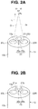
- FIG. 2A illustrates a case in which one illumination window 21 is provided
- two illumination windows 21a and 21 b may be provided as shown in Fig. 2B .
- one light guide 31 is branched into two light guides in the stereoscopic endoscope 2, and distal ends of the two light guides are fixed to the illumination windows 21a and 21b.
- An illumination lens 35 described later is attached to the illumination window 21 through a lens frame.
- the illumination lens 35 is also attached to each window.
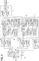
- the left and right image signals generated by the signal processing circuits 42a and 42b are inputted to adjustment circuit units 5A and 5B, respectively, included in the adjustment unit 5.
- a read/write circuit 54a performs writing (write) and reading (read) of the image signal to and from the first memory 51 a and the second memory 52a.
- a control circuit 55a controls operation of read/write of the read/write circuit 54a.
- the second memory 52a stores an image (also called a cut-out image) in the cut-out range 44La on the center side obtained by removing an effective pixel region 45La on a peripheral side from the effective pixel region 43La. Therefore, the second memory 52a forms a cut-out image generation section (or a cut-out image storage section) configured to generate or store the cut-out image. Note that it can also be defined that the cut-out image generation section (cut-out image generation circuit) configured to generate the cut-out image includes the first memory 51a, the enlargement circuit 50a, the second memory 52a, and the read/write circuit 54a.
- the image signal picked up in the effective pixel region 43La is displayed on the 3D monitor 7 as the left image in the 3D image.
- the image signal picked up (photoelectrically converted) in the effective pixel region 43La is also inputted to the control circuit 55a, and the control circuit 55a has a function of executing an adjustment process as described below.
- the memory 56a stores reference data that is data of reference coordinates that are coordinates (Xl1, Yl1) and (Xr1, Yr1) of two-dimensional positions of the index 25b (center of the index 25b) when image of the index 25b is picked up in an adjusted state.
- the positions of the centers of the effective pixel regions 43La and 43Ra are adjusted to coincide when image of the predetermined position P0 (see Fig.
- the adjustment circuit unit 5B includes components with ⁇ b in place of ⁇ a of the first memory 51a, the enlargement circuit 50a, the second memory 52a, the switching circuit 53a, the read/write circuit 54a, the control circuit 55a, and the memory 56a in the adjustment circuit unit 5A. Only the inputted signal is different, and the components and the functions are the same. The description will not be repeated.
- an adjustment section configured to adjust at least one of the image pickup sections to generate substantially horizontally symmetrical images when the first image and the second image obtained by picking up the images of the reference member by the first and second image pickup devices are displayed as left and right images in the display region of the display apparatus will be described later in Fig. 8 .
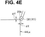
- the left and right coordinates (Xl1, Yl1) and (Xr1, Yr1) indicating the positions of the index 25b are horizontally symmetrical to each other with respect to the coordinates (X10, Y10) and (Xr0, Yr0) of the center positions.
- the coordinates (Xl1, Yl1) and (Xr1, Yr1) serve as respective reference positions, and the rectangular cut-out ranges 44La and 44Ra are set. More specifically, the coordinates (Xl1, Yl1) and (Xr1, Yr1) serve as an upper right peak and an upper left peak that are boundary positions of the cut-out ranges, and the cut-out ranges 44La and 44Ra are set, respectively.
- the cut-out ranges 44La and 44Ra are displayed on the 3D monitor 7, the coordinates (Xl1, Yl1) and (Xr1, and Yr1) of the index 25b are boundary positions not displayed.
- the cut-out ranges 44La and 44Ra are set to display regions of normal images (signals) in the 3D monitor 7. That is, as shown in Fig.
- the cut-out range setting sections 55a3 and 55b3 perform an adjustment of moving the cut-out ranges 44La and 44Ra (in the movement direction of the index and by the amount of movement) to bring the coordinates (Xl1, and (Xr1, Yr1) of the index 25b as reference positions into line with the coordinates (Xl2, Yl2) and (Xr2, Yr2) of the extracted new index 25b.
- the coordinates (X10, Y10) of the adjusted center position shown in Fig. 4A are shifted by the amount equivalent to the difference value and moved to coordinates (X10', Y10') of the center position.
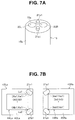
- the illumination lens frames 21a1 and 21b1 are provided to protrude from the distal end surface 15a to provide the function of index members in a normal stereoscopic endoscope, and therefore, there is an advantage that the index member 25 necessary for the adjustment does not have to be newly provided.
- the case is not limited to the case in which two illumination lens frames 21a1 and 21b1 are provided to protrude from the distal end surface 15a, and one illumination lens frame may be provided to protrude from the distal end surface 15a.
- Fig. 7C shows a case in which, for example, the position of the coordinates (Xlb1, Ylb1) does not change, and the other coordinates (Xla1, Yla1) are changed.
- the adjustment unit 5 forming the adjustment section includes, for example, the difference value calculation section 55a2 as a judgement circuit configured to judge whether the position data of the indexes whose images are picked up in the left and right peripheral side effective pixel regions at the adjustment instruction exists in the ranges (predetermined ranges Lu1 and Lu2) of the thresholds set in advance with respect to the reference position data of the indexes whose images are picked up in the left and right peripheral side effective pixel regions in the adjusted state. If the judgement result of the judgement circuit indicates that at least one of the left and right position data is out of the ranges of the thresholds, a warning is issued. That is, the difference value calculation section 55a2 forming the judgement circuit functions as a notification section (or a notification circuit) configured to notify the user such as a display for warning or the like.
- the user such as an operator, can check the generation of a deviation in a level that it is better to perform mechanical adjustment, in at least one of the both image pickup sections 22L and 22R.
- the user can set the state for obtaining a predetermined performance by performing the mechanical adjustment before the next use of the stereoscopic endoscope 2, for example.
- the state for obtaining the predetermined performance can be checked even in a state in which the stereoscopic endoscope 2 is repeatedly used for a long time, and timing for performing the mechanical adjustment can be recognized.
- the illumination lens frames 21a1 and 21b1 are used as the reference members in the description, the illumination lens 35 may be protruded from the distal end surface 15a, and the protruding illumination lens 35 may be used as the reference member.
- the through hole 72L can rotate the image pickup unit 71L about the optical axis Ol in a range of a predetermined angle, and the through hole 72L includes an air gap that allows fixing the image pickup unit 71L by slightly tilting the image pickup unit 71L from the direction of the optical axis Ol.
- the image pickup unit 71L is adjusted to be horizontally symmetrical to the image pickup unit 71R, and the image pickup unit 71L is fixed by a screw, an adhesive 79L, or the like.
- the image pickup section frame body 75R of the image pickup unit 71R is inserted, from behind, into the through hole 72R in the distal end portion main body 15c and is fixed to the through hole 72R in a state that the image pickup section frame body 75R is positioned at the positioning tapered portion 77R.
- the image pickup section frame body 75R is fixed such that the direction of the optical axis Or of the image pickup unit 71R becomes a predetermined field of view direction Vr and is fixed by setting an azimuth in a circumferential direction of the image pickup unit 71R (rotation angle ⁇ Rr about the optical axis Or) to a predetermined azimuth (that is, fixed in a state that the inclination is eliminated).
- the adjustment section configured to adjust at least one image pickup section of the first image pickup section and the second image pickup section adjusts the rotation angle of the one image pickup section about the optical axis direction to fix the one image pickup section to the one through hole and adjusts the rotation angle of the other image pickup section about the optical axis of the other image pickup section and the inclination of the optical axis to fix the other image pickup section to the other through hole such that one image of a first image and a second image of the index member 25 as a reference member picked up by the first image pickup section and the second image pickup section becomes horizontally symmetrical to the other image of the first image and the second image.
- the frame body of one image pickup section (more specifically, 22R) or image pickup unit (more specifically, 71R) is fixed in the through hole 72R in the distal end portion main body 15c at the rotation angle ⁇ Rr about the optical axis Or, and the inclination angle ⁇ Ld of the optical axis Ol and the rotation angle ⁇ Lr are adjusted to fix (attach) the other image pickup section 22L or image pickup unit 71L to the through hole 72L in the distal end portion main body 15c in the state that the other image pickup section 22L or image pickup unit 71 L becomes horizontally symmetrical to the image pickup section 22R or the image pickup unit 71R.
- Fig. 9 shows a configuration of the distal end portion 15 in the stereoscopic endoscope 2 (see Fig. 10 ) according to the present embodiment.
- the light source apparatus 3, the CCUs 4A and 4B, the adjustment unit 5, the 3D mixer 6, and the 3D monitor 7 other than the stereoscopic endoscope 2 are the same as in the first embodiment.
- distal end portion 15 is provided with, for example, the illumination lens frames 21a1 and 21b1 as shown in Fig. 6 as index members forming reference members described in the first embodiment.
- Tapered notch portions 84r and 841 are formed on rear end sides of frame bodies 75L' and 75R' holding the objective optical systems 23L and 23R and the CCDs 24L and 24R in the image pickup units 71L and 71R.
- a trapezoidal abutment member 85 abuts the notch portions 84r and 841, and the abutment member 85 is urged such that elastic force pulls the abutment member 85 toward a support member on the distal end side through a spring 86.
- the wire 81 may be slightly slackened according to a case in which the insertion portion 11 is inserted into a bent site or the like. In such a case, the slackening is eliminated by the elastic force of the spring 86, and the abutment member 85 is brought into contact with the notch portions 84r and 841 to set a state of the predetermined inward angle ⁇ i. However, a structure without the spring 86 is possible if the slacking can be ignored.
- the image pickup unit 71R shown in Fig. 9 is simply illustrated, in which, for example, the connection portion 74R part is reshaped into a connection portion provided with electronic components in the image pickup unit 71 R of Fig. 8 , and the image pickup section frame body 75R and the lens frame body 76R are collectively expressed by a frame body 75R'.
- the image pickup unit 71L shown in Fig. 9 also has the same configuration. Note that the distal end portion 15c is sealed by another frame member (not shown) and a cover glass (not shown), and water tightness is maintained.
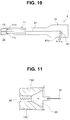
- the wire 81 is inserted into the insertion portion 11 as shown in a schematic diagram of Fig. 10 , and a rear end of the wire 81 is wound around and attached to a pulley 87 in the operation portion 12 on the hand side of the stereoscopic endoscope 2.
- the pulley 87 is provided with a knob 87a as a hand side pulling operation object for rotating the pulley 87 to pull the wire 81, and the user can perform operation of rotating the knob 87a to change the inward angle ⁇ 1.
- the image pickup units 71R and 71L shown in Fig. 9 are movable relative to the distal end portion 15c. Therefore, the distance L between the point of intersection P0 of the both optical axes Ol and Or and the distal end surface and a distance (or optical axis interval) Ld between the optical axes of the image pickup units 71R and 71 L on the distal end surface are changed to change the inward angle ⁇ i. Note that the distance (or optical axis interval) Ld between the optical axes of the image pickup units 71R and 71L on the distal end surface can also be called an interval between the both field of view directions Vl and Vr on the distal end surface.
- the abutment member 85 moves toward the back side as indicated by a dotted line in Fig. 11 .
- the elastic force of the springs 83a and 83b rotates and moves the back side parts of the frame bodies 75L' and 75R' inside, with positions on the distal end side (positions supported by the tapered portions 82a and 82a) as fulcrums.
- the optical axes Ol and Or of the image pickup units 71L and 71R change due to the urging force of the spring 86, and the distance L between the point of intersection P0 and the distal end surface becomes short.
- the optical axis interval Ld becomes wide due to the distance between the distal end surface and the contact point Ps of the image pickup units 71L and 71R and the distal end surface 15c, and the inward angle ⁇ i can be increased.
- Fig. 12 shows a schematic configuration of the stereoscopic endoscope 2 in this case.
- An actuator 88a configured to move the wire 81 in a longitudinal direction of the wire 81 is provided inside of the operation portion 12, and a drive circuit 88c configured to drive the actuator 88a is housed in one connector 88b of connectors (the other connector is not shown) provided on the end portion of the universal cable 13.
- the operation portion 12 is also provided with a switching circuit 88d configured to perform operation of changing the inward angle ⁇ i, and based on a signal of the switching circuit 88d, the drive circuit 88c applies a drive signal for driving the actuator 88a to the actuator 88a.
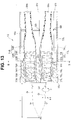
- Fig. 13 shows a configuration of the distal end portion 15 according to the second modification
- Fig. 14 shows a B-B cross-sectional view of Fig. 13 .
- one image pickup unit 71R of the image pickup units is fixed to the distal end portion main body 15c like the one shown in Fig. 8 .
- the other image pickup unit 71 L abuts the tapered portion 77L of the distal end portion main body 15c and is supported such that the optical axis Ol direction can be changed.
- the image pickup section frame body 75L of the image pickup unit 71L is provided with wire attachment portions 91u, 91d, 911, and 91r for attaching distal ends of wires 81u, 81d, 811, and 81r at vertical and horizontal positions on the outer circumferential face, at positions on the back side of the tapered portion 77L.
- Fig. 13 shows two wires 811 and 81r and two wire attachment portions 911 and 91r
- Fig. 14 shows the wire attachment portions 91u, 91 d, 911, and 91r at four parts.
- wire receivers 92u, 92d, 921, and 92r for restricting the expansion of the wires 81 u, 81d, 811, and 81r to the center side closer to the optical axis Ol are provided at positions on the back side of the wire attachment portions 91u, 91d, 911, and 91r in the distal end portion 15.
- the wire receivers 92u, 92d, 921, and 92r are formed by providing through holes in a wire receiving member 92.
- the rear end side of the wires 81u, 81d, 811, and 81r having passed through the wire receivers 92u, 92d, 921, and 92r, respectively, is wound around the pulley 87 as shown in Fig. 10 , for example.
- the wires 81u and 81d are wound around one pulley (87a, although not shown) from directions opposite to each other, and the wires 811 and 81r are wound around another pulley (87b, although not shown) from directions opposite to each other.
- the pulley 87a when the pulley 87a is rotated and operated to pull the wire 811 to the hand side for example, force for rotating the rear end side of the image pickup unit 71L to the center axis side of the distal end portion 15 acts on the image pickup unit 71L with the tapered portion 77L as a fulcrum.
- the optical axis Ol changes relative to the optical axis Or.
- the distance L between the point of intersection P0 of the optical axis Or and the optical axis Ol and the distal end surface becomes long, and the distance Ld between optical axes of the optical axis Or and the optical axis Ol becomes short. Therefore, the inward angle ⁇ i becomes small.
- the optical axis Ol changes relative to the optical axis Or, and the distance L between the point of intersection P0 of the optical axis Or and the optical axis Ol and the distal end surface becomes short, and the distance Ld between optical axes of the optical axis Or and the optical axis Ol becomes short. Therefore, the inward angle ⁇ i becomes large.
- the inward angle can be changed by the operation on the hand side.
- the direction of the optical axis Ol that is, the field of view direction Vl can also be changed to a direction perpendicular to the horizontal surface including the both optical axes Ol and Or.
- the direction (azimuth) (around the optical axis) of providing the wire attachment portions 91u, 91d, 911, and 91r may be changed.
- the direction of providing the wire attachment portions 91 u, 91 d, 911, and 91 r is changed to, for example, positions rotated about 45 degrees from the configuration of Fig. 14 .
- a space for more widely changing the optical axis Ol direction of the image pickup unit 71L in the distal end portion 15 can be secured.
- the outer diameter of the distal end portion 15 can be reduced.
- wire attachment portions 911 and 91r for attaching (fixing) the distal ends of the wires 81u, 81d, 811, and 81r for changing or adjusting the direction of the optical axis Ol are provided on the outer circumferential face of the image pickup section frame body 75L in the present modification
- a ring (will be called an adjustment ring) provided with the wire attachment portions 91 u, 91 d, 911, and 91r may be provided on the outer circumferential face of the image pickup section frame body 75L.
- a fourth modification shown in Fig. 16 shows a case in which an adjustment ring 95 is used.
- the thickness of the image pickup section frame body 75L is reduced, and the adjustment ring 95 provided with the wire attachment portions 91 u, 91 d, 911, and 91r r is provided on the outer circumferential face of the image pickup section frame body 75L.
- a D-cut portion 96 is also provided in a predetermined direction on the image pickup section frame body 75L to facilitate the positioning in the circumferential direction in attaching the adjustment ring 95 to the image pickup section frame body 75L, and the adjustment ring 95 is shaped to suit the D-cut portion 96.
- direction index data may be stored in advance in the memories 56a and 56b in the adjustment unit 5 of Fig. 3 to display direction indexes indicating an upward direction and a left direction when images of the effective pixel regions 43La and 43Ra are displayed.
- a direction index 94a of the upward direction and a direction index 94b of the left direction may be displayed as indicated by, for example, dotted lines in Fig. 4C to allow easily recognizing the vertical and horizontal directions of the image pickup sections 22L and 22R and the image pickup units 77L and 77R.
- Embodiments formed by partially combining the embodiments described above including the modifications also belong to the present invention.
Landscapes
- Physics & Mathematics (AREA)
- Health & Medical Sciences (AREA)
- Life Sciences & Earth Sciences (AREA)
- Surgery (AREA)
- Optics & Photonics (AREA)
- Engineering & Computer Science (AREA)
- General Health & Medical Sciences (AREA)
- Radiology & Medical Imaging (AREA)
- Medical Informatics (AREA)
- Veterinary Medicine (AREA)
- Biomedical Technology (AREA)
- Heart & Thoracic Surgery (AREA)
- Nuclear Medicine, Radiotherapy & Molecular Imaging (AREA)
- Molecular Biology (AREA)
- Animal Behavior & Ethology (AREA)
- Biophysics (AREA)
- Public Health (AREA)
- Pathology (AREA)
- Astronomy & Astrophysics (AREA)
- General Physics & Mathematics (AREA)
- Multimedia (AREA)
- Signal Processing (AREA)
- Endoscopes (AREA)
- Instruments For Viewing The Inside Of Hollow Bodies (AREA)
- Closed-Circuit Television Systems (AREA)
- Testing, Inspecting, Measuring Of Stereoscopic Televisions And Televisions (AREA)
Applications Claiming Priority (2)
| Application Number | Priority Date | Filing Date | Title |
|---|---|---|---|
| JP2013252144 | 2013-12-05 | ||
| PCT/JP2014/078570 WO2015083459A1 (fr) | 2013-12-05 | 2014-10-28 | Système d'endoscope stéréoscopique |
Publications (2)
| Publication Number | Publication Date |
|---|---|
| EP3064122A1 true EP3064122A1 (fr) | 2016-09-07 |
| EP3064122A4 EP3064122A4 (fr) | 2017-09-06 |
Family
ID=53273234
Family Applications (1)
| Application Number | Title | Priority Date | Filing Date |
|---|---|---|---|
| EP14867107.6A Withdrawn EP3064122A4 (fr) | 2013-12-05 | 2014-10-28 | Système d'endoscope stéréoscopique |
Country Status (5)
| Country | Link |
|---|---|
| US (1) | US9599810B2 (fr) |
| EP (1) | EP3064122A4 (fr) |
| JP (1) | JP5897222B2 (fr) |
| CN (1) | CN105764402B (fr) |
| WO (1) | WO2015083459A1 (fr) |
Families Citing this family (23)
| Publication number | Priority date | Publication date | Assignee | Title |
|---|---|---|---|---|
| US10750930B2 (en) * | 2014-11-06 | 2020-08-25 | Sony Corporation | Endoscope apparatus and method for operating endoscope apparatus |
| EP3275359A1 (fr) * | 2015-05-12 | 2018-01-31 | Olympus Corporation | Dispositif endoscope stéréoscopique |
| EP3281576A1 (fr) * | 2015-05-14 | 2018-02-14 | Olympus Corporation | Dispositif d'endoscope stéréoscopique |
| WO2017098755A1 (fr) * | 2015-12-08 | 2017-06-15 | オリンパス株式会社 | Appareil d'imagerie stéréoscopique |
| JP6629639B2 (ja) * | 2016-03-07 | 2020-01-15 | 富士フイルム株式会社 | 内視鏡システム、プロセッサ装置、及び、内視鏡システムの作動方法 |
| JP6437943B2 (ja) * | 2016-03-07 | 2018-12-12 | 富士フイルム株式会社 | 内視鏡システム、プロセッサ装置、及び、内視鏡システムの作動方法 |
| US11782256B2 (en) * | 2016-09-21 | 2023-10-10 | Omnivision Technologies, Inc. | Endoscope imager and associated method |
| DE112017006551T5 (de) * | 2016-12-26 | 2019-09-26 | Olympus Corporation | Stereo-Bildaufnahmeeinheit |
| JP6422621B1 (ja) | 2017-05-01 | 2018-11-14 | オリンパス株式会社 | 内視鏡撮像装置 |
| WO2018225397A1 (fr) * | 2017-06-06 | 2018-12-13 | オリンパス株式会社 | Endoscope stéréoscopique |
| WO2019003587A1 (fr) * | 2017-06-30 | 2019-01-03 | オリンパス株式会社 | Endoscope |
| EP3649913A4 (fr) * | 2017-08-03 | 2020-07-08 | Sony Olympus Medical Solutions Inc. | Dispositif d'observation médicale |
| US20200261180A1 (en) * | 2017-09-06 | 2020-08-20 | Covidien Lp | 27-3systems, methods, and computer-readable media for providing stereoscopic visual perception notifications and/or recommendations during a robotic surgical procedure |
| WO2019220916A1 (fr) | 2018-05-14 | 2019-11-21 | 富士フイルム株式会社 | Dispositif de traitement d'image médicale, méthode de traitement d'image médicale et système d'endoscope |
| JP6987243B2 (ja) * | 2018-06-22 | 2021-12-22 | オリンパス株式会社 | ランドマーク推定方法、内視鏡装置、及び、位置推定プログラム |
| CN109222862B (zh) * | 2018-09-20 | 2021-02-19 | 深圳市精锋医疗科技有限公司 | 内窥镜、操作臂、从操作设备及手术机器人 |
| CN109222861B (zh) * | 2018-09-20 | 2022-03-04 | 深圳市精锋医疗科技股份有限公司 | 内窥镜、操作臂、从操作设备及手术机器人 |
| CN109222860B (zh) * | 2018-09-20 | 2021-09-24 | 深圳市精锋医疗科技有限公司 | 可调节内窥镜、操作臂、从操作设备及手术机器人 |
| CN114652261A (zh) * | 2018-09-20 | 2022-06-24 | 深圳市精锋医疗科技股份有限公司 | 内窥镜及手术机器人 |
| JP2020162633A (ja) | 2019-03-28 | 2020-10-08 | ソニー株式会社 | 撮影制御装置、撮影制御方法、プログラム、及び、撮影システム |
| CN113316738B (zh) * | 2019-08-06 | 2024-05-17 | 松下知识产权经营株式会社 | 显示装置 |
| CN111067477A (zh) * | 2019-12-28 | 2020-04-28 | 山东第一医科大学(山东省医学科学院) | 一种眼科房角眼前节图像分析系统 |
| CN116055828B (zh) * | 2022-12-30 | 2025-05-30 | 杭州微影软件有限公司 | 图像获取设备 |
Family Cites Families (14)
| Publication number | Priority date | Publication date | Assignee | Title |
|---|---|---|---|---|
| JP3257640B2 (ja) | 1992-06-09 | 2002-02-18 | オリンパス光学工業株式会社 | 立体視内視鏡装置 |
| JPH08126606A (ja) * | 1994-10-31 | 1996-05-21 | Olympus Optical Co Ltd | 内視鏡システム |
| DE69627497T2 (de) * | 1995-05-24 | 2003-12-24 | Olympus Optical Co., Ltd. | Stereoskopisches endoskop und tv-bildaufnahmesystem für das endoskop |
| US6464633B1 (en) * | 1999-08-23 | 2002-10-15 | Olympus Optical Co., Ltd. | Light source device for endoscope using DMD |
| JP4610799B2 (ja) * | 2001-06-25 | 2011-01-12 | オリンパス株式会社 | 立体観察システム、及び内視鏡装置 |
| US7170677B1 (en) * | 2002-01-25 | 2007-01-30 | Everest Vit | Stereo-measurement borescope with 3-D viewing |
| JP2007044153A (ja) * | 2005-08-08 | 2007-02-22 | Olympus Medical Systems Corp | 立体視内視鏡装置 |
| WO2011114572A1 (fr) * | 2010-03-19 | 2011-09-22 | 富士フイルム株式会社 | Dispositif, procédé et programme d'imagerie et support d'enregistrement associé |
| JP5290233B2 (ja) * | 2010-04-13 | 2013-09-18 | Ckd株式会社 | 三次元計測装置及び基板検査装置 |
| JP4955840B2 (ja) * | 2010-07-09 | 2012-06-20 | オリンパスメディカルシステムズ株式会社 | 立体内視鏡 |
| JP5253688B1 (ja) * | 2011-08-10 | 2013-07-31 | オリンパスメディカルシステムズ株式会社 | 内視鏡装置 |
| US9456735B2 (en) * | 2012-09-27 | 2016-10-04 | Shahinian Karnig Hrayr | Multi-angle rear-viewing endoscope and method of operation thereof |
| JP5973707B2 (ja) * | 2011-10-14 | 2016-08-23 | オリンパス株式会社 | 三次元内視鏡装置 |
| CN202801544U (zh) * | 2012-09-25 | 2013-03-20 | 天津博朗科技发展有限公司 | 立体内窥镜校正筒 |
-
2014
- 2014-10-28 WO PCT/JP2014/078570 patent/WO2015083459A1/fr not_active Ceased
- 2014-10-28 JP JP2015533365A patent/JP5897222B2/ja active Active
- 2014-10-28 EP EP14867107.6A patent/EP3064122A4/fr not_active Withdrawn
- 2014-10-28 CN CN201480064281.5A patent/CN105764402B/zh active Active
-
2016
- 2016-05-19 US US15/159,223 patent/US9599810B2/en active Active
Also Published As
| Publication number | Publication date |
|---|---|
| WO2015083459A9 (fr) | 2016-04-14 |
| US9599810B2 (en) | 2017-03-21 |
| CN105764402B (zh) | 2018-02-13 |
| JPWO2015083459A1 (ja) | 2017-03-16 |
| WO2015083459A1 (fr) | 2015-06-11 |
| CN105764402A (zh) | 2016-07-13 |
| EP3064122A4 (fr) | 2017-09-06 |
| JP5897222B2 (ja) | 2016-03-30 |
| US20160259159A1 (en) | 2016-09-08 |
Similar Documents
| Publication | Publication Date | Title |
|---|---|---|
| EP3064122A1 (fr) | Système d'endoscope stéréoscopique | |
| JP5730339B2 (ja) | 立体内視鏡装置 | |
| JP7178385B2 (ja) | 撮像システムおよび観察方法 | |
| JP7294776B2 (ja) | 内視鏡プロセッサ、表示設定方法、表示設定プログラムおよび内視鏡システム | |
| CN110944567B (zh) | 医疗观察装置 | |
| JP2014151150A (ja) | 内視鏡及び内視鏡装置 | |
| JP6210874B2 (ja) | 立体観察装置の調整治具及び立体観察システム | |
| JP2013106189A (ja) | 撮像装置 | |
| JP2017038285A (ja) | 医療用観察装置、制御装置、制御装置の作動方法および制御装置の作動プログラム | |
| JP6666467B2 (ja) | 医療用観察装置、及び制御方法 | |
| US20120300032A1 (en) | Endoscope | |
| JP6253857B1 (ja) | 立体内視鏡および立体内視鏡システム | |
| CN107529953B (zh) | 立体摄像单元 | |
| JP3599778B2 (ja) | 立体視内視鏡システム | |
| WO2019069548A1 (fr) | Dispostif de capture d'image, unité de commande de dispositif de capture d'image et procédé de capture d'image | |
| EP4205691A1 (fr) | Dispositif de traitement d'image médicale et système d'observation médicale | |
| JP5818265B2 (ja) | 立体内視鏡装置 | |
| JPH1028233A (ja) | 内視鏡用撮像装置 | |
| JP2019154734A (ja) | 医療用画像処理装置、医療用観察装置、および画像処理方法 | |
| JP2016185342A (ja) | 内視鏡及び内視鏡装置 | |
| JP2019050508A (ja) | 立体視撮像装置および立体視内視鏡 | |
| JP2018149090A (ja) | 医療用撮像装置及び医療用観察システム | |
| JP2013254124A (ja) | 立体撮像光学系及びそれを備えた内視鏡 | |
| JP4882489B2 (ja) | 立体画像表示装置 | |
| WO2019107359A1 (fr) | Dispositif d'imagerie |
Legal Events
| Date | Code | Title | Description |
|---|---|---|---|
| PUAI | Public reference made under article 153(3) epc to a published international application that has entered the european phase |
Free format text: ORIGINAL CODE: 0009012 |
|
| 17P | Request for examination filed |
Effective date: 20160524 |
|
| AK | Designated contracting states |
Kind code of ref document: A1 Designated state(s): AL AT BE BG CH CY CZ DE DK EE ES FI FR GB GR HR HU IE IS IT LI LT LU LV MC MK MT NL NO PL PT RO RS SE SI SK SM TR |
|
| AX | Request for extension of the european patent |
Extension state: BA ME |
|
| RAP1 | Party data changed (applicant data changed or rights of an application transferred) |
Owner name: OLYMPUS CORPORATION |
|
| RAP1 | Party data changed (applicant data changed or rights of an application transferred) |
Owner name: OLYMPUS CORPORATION |
|
| RIN1 | Information on inventor provided before grant (corrected) |
Inventor name: USHIJIMA, TAKANORI Inventor name: MATSUI, TOSHIHIRO |
|
| DAX | Request for extension of the european patent (deleted) | ||
| A4 | Supplementary search report drawn up and despatched |
Effective date: 20170803 |
|
| RIC1 | Information provided on ipc code assigned before grant |
Ipc: H04N 7/18 20060101ALI20170728BHEP Ipc: A61B 1/00 20060101AFI20170728BHEP Ipc: H04N 13/00 20060101ALI20170728BHEP Ipc: A61B 1/04 20060101ALI20170728BHEP Ipc: G02B 23/26 20060101ALI20170728BHEP |
|
| STAA | Information on the status of an ep patent application or granted ep patent |
Free format text: STATUS: REQUEST FOR EXAMINATION WAS MADE |
|
| STAA | Information on the status of an ep patent application or granted ep patent |
Free format text: STATUS: THE APPLICATION IS DEEMED TO BE WITHDRAWN |
|
| 18D | Application deemed to be withdrawn |
Effective date: 20180302 |