EP3064166A1 - Hermetisch abgedichtete led-leuchte sowie verfahren zur herstellung einer hermetisch abgedichteten led-leuchte - Google Patents
Hermetisch abgedichtete led-leuchte sowie verfahren zur herstellung einer hermetisch abgedichteten led-leuchte Download PDFInfo
- Publication number
- EP3064166A1 EP3064166A1 EP16157312.6A EP16157312A EP3064166A1 EP 3064166 A1 EP3064166 A1 EP 3064166A1 EP 16157312 A EP16157312 A EP 16157312A EP 3064166 A1 EP3064166 A1 EP 3064166A1
- Authority
- EP
- European Patent Office
- Prior art keywords
- hermetically sealed
- led lamp
- metal cap
- windows
- sealed led
- Prior art date
- Legal status (The legal status is an assumption and is not a legal conclusion. Google has not performed a legal analysis and makes no representation as to the accuracy of the status listed.)
- Granted
Links
Images


Classifications
-
- F—MECHANICAL ENGINEERING; LIGHTING; HEATING; WEAPONS; BLASTING
- F21—LIGHTING
- F21V—FUNCTIONAL FEATURES OR DETAILS OF LIGHTING DEVICES OR SYSTEMS THEREOF; STRUCTURAL COMBINATIONS OF LIGHTING DEVICES WITH OTHER ARTICLES, NOT OTHERWISE PROVIDED FOR
- F21V33/00—Structural combinations of lighting devices with other articles, not otherwise provided for
- F21V33/0064—Health, life-saving or fire-fighting equipment
- F21V33/0068—Medical equipment
-
- A—HUMAN NECESSITIES
- A61—MEDICAL OR VETERINARY SCIENCE; HYGIENE
- A61B—DIAGNOSIS; SURGERY; IDENTIFICATION
- A61B1/00—Instruments for performing medical examinations of the interior of cavities or tubes of the body by visual or photographical inspection, e.g. endoscopes; Illuminating arrangements therefor
- A61B1/06—Instruments for performing medical examinations of the interior of cavities or tubes of the body by visual or photographical inspection, e.g. endoscopes; Illuminating arrangements therefor with illuminating arrangements
- A61B1/0661—Endoscope light sources
- A61B1/0684—Endoscope light sources using light emitting diodes [LED]
-
- A—HUMAN NECESSITIES
- A61—MEDICAL OR VETERINARY SCIENCE; HYGIENE
- A61C—DENTISTRY; APPARATUS OR METHODS FOR ORAL OR DENTAL HYGIENE
- A61C1/00—Dental machines for boring or cutting ; General features of dental machines or apparatus, e.g. hand-piece design
- A61C1/08—Machine parts specially adapted for dentistry
- A61C1/088—Illuminating devices or attachments
-
- A—HUMAN NECESSITIES
- A61—MEDICAL OR VETERINARY SCIENCE; HYGIENE
- A61C—DENTISTRY; APPARATUS OR METHODS FOR ORAL OR DENTAL HYGIENE
- A61C3/00—Dental tools or instruments
- A61C3/02—Tooth drilling or cutting instruments; Instruments acting like a sandblast machine
-
- F—MECHANICAL ENGINEERING; LIGHTING; HEATING; WEAPONS; BLASTING
- F21—LIGHTING
- F21K—NON-ELECTRIC LIGHT SOURCES USING LUMINESCENCE; LIGHT SOURCES USING ELECTROCHEMILUMINESCENCE; LIGHT SOURCES USING CHARGES OF COMBUSTIBLE MATERIAL; LIGHT SOURCES USING SEMICONDUCTOR DEVICES AS LIGHT-GENERATING ELEMENTS; LIGHT SOURCES NOT OTHERWISE PROVIDED FOR
- F21K9/00—Light sources using semiconductor devices as light-generating elements, e.g. using light-emitting diodes [LED] or lasers
- F21K9/20—Light sources comprising attachment means
-
- F—MECHANICAL ENGINEERING; LIGHTING; HEATING; WEAPONS; BLASTING
- F21—LIGHTING
- F21K—NON-ELECTRIC LIGHT SOURCES USING LUMINESCENCE; LIGHT SOURCES USING ELECTROCHEMILUMINESCENCE; LIGHT SOURCES USING CHARGES OF COMBUSTIBLE MATERIAL; LIGHT SOURCES USING SEMICONDUCTOR DEVICES AS LIGHT-GENERATING ELEMENTS; LIGHT SOURCES NOT OTHERWISE PROVIDED FOR
- F21K9/00—Light sources using semiconductor devices as light-generating elements, e.g. using light-emitting diodes [LED] or lasers
- F21K9/90—Methods of manufacture
-
- F—MECHANICAL ENGINEERING; LIGHTING; HEATING; WEAPONS; BLASTING
- F21—LIGHTING
- F21V—FUNCTIONAL FEATURES OR DETAILS OF LIGHTING DEVICES OR SYSTEMS THEREOF; STRUCTURAL COMBINATIONS OF LIGHTING DEVICES WITH OTHER ARTICLES, NOT OTHERWISE PROVIDED FOR
- F21V17/00—Fastening of component parts of lighting devices, e.g. shades, globes, refractors, reflectors, filters, screens, grids or protective cages
- F21V17/10—Fastening of component parts of lighting devices, e.g. shades, globes, refractors, reflectors, filters, screens, grids or protective cages characterised by specific fastening means or way of fastening
- F21V17/101—Fastening of component parts of lighting devices, e.g. shades, globes, refractors, reflectors, filters, screens, grids or protective cages characterised by specific fastening means or way of fastening permanently, e.g. welding, gluing or riveting
-
- F—MECHANICAL ENGINEERING; LIGHTING; HEATING; WEAPONS; BLASTING
- F21—LIGHTING
- F21V—FUNCTIONAL FEATURES OR DETAILS OF LIGHTING DEVICES OR SYSTEMS THEREOF; STRUCTURAL COMBINATIONS OF LIGHTING DEVICES WITH OTHER ARTICLES, NOT OTHERWISE PROVIDED FOR
- F21V3/00—Globes; Bowls; Cover glasses
-
- F—MECHANICAL ENGINEERING; LIGHTING; HEATING; WEAPONS; BLASTING
- F21—LIGHTING
- F21V—FUNCTIONAL FEATURES OR DETAILS OF LIGHTING DEVICES OR SYSTEMS THEREOF; STRUCTURAL COMBINATIONS OF LIGHTING DEVICES WITH OTHER ARTICLES, NOT OTHERWISE PROVIDED FOR
- F21V31/00—Gas-tight or water-tight arrangements
- F21V31/005—Sealing arrangements therefor
-
- G—PHYSICS
- G02—OPTICS
- G02B—OPTICAL ELEMENTS, SYSTEMS OR APPARATUS
- G02B23/00—Telescopes, e.g. binoculars; Periscopes; Instruments for viewing the inside of hollow bodies; Viewfinders; Optical aiming or sighting devices
- G02B23/24—Instruments or systems for viewing the inside of hollow bodies, e.g. fibrescopes
- G02B23/2407—Optical details
- G02B23/2461—Illumination
-
- G—PHYSICS
- G02—OPTICS
- G02B—OPTICAL ELEMENTS, SYSTEMS OR APPARATUS
- G02B23/00—Telescopes, e.g. binoculars; Periscopes; Instruments for viewing the inside of hollow bodies; Viewfinders; Optical aiming or sighting devices
- G02B23/24—Instruments or systems for viewing the inside of hollow bodies, e.g. fibrescopes
- G02B23/2476—Non-optical details, e.g. housings, mountings, supports
- G02B23/2484—Arrangements in relation to a camera or imaging device
-
- H—ELECTRICITY
- H10—SEMICONDUCTOR DEVICES; ELECTRIC SOLID-STATE DEVICES NOT OTHERWISE PROVIDED FOR
- H10H—INORGANIC LIGHT-EMITTING SEMICONDUCTOR DEVICES HAVING POTENTIAL BARRIERS
- H10H20/00—Individual inorganic light-emitting semiconductor devices having potential barriers, e.g. light-emitting diodes [LED]
- H10H20/01—Manufacture or treatment
-
- H—ELECTRICITY
- H10—SEMICONDUCTOR DEVICES; ELECTRIC SOLID-STATE DEVICES NOT OTHERWISE PROVIDED FOR
- H10W—GENERIC PACKAGES, INTERCONNECTIONS, CONNECTORS OR OTHER CONSTRUCTIONAL DETAILS OF DEVICES COVERED BY CLASS H10
- H10W90/00—Package configurations
-
- F—MECHANICAL ENGINEERING; LIGHTING; HEATING; WEAPONS; BLASTING
- F21—LIGHTING
- F21W—INDEXING SCHEME ASSOCIATED WITH SUBCLASSES F21K, F21L, F21S and F21V, RELATING TO USES OR APPLICATIONS OF LIGHTING DEVICES OR SYSTEMS
- F21W2131/00—Use or application of lighting devices or systems not provided for in codes F21W2102/00-F21W2121/00
- F21W2131/20—Lighting for medical use
-
- F—MECHANICAL ENGINEERING; LIGHTING; HEATING; WEAPONS; BLASTING
- F21—LIGHTING
- F21Y—INDEXING SCHEME ASSOCIATED WITH SUBCLASSES F21K, F21L, F21S and F21V, RELATING TO THE FORM OR THE KIND OF THE LIGHT SOURCES OR OF THE COLOUR OF THE LIGHT EMITTED
- F21Y2101/00—Point-like light sources
-
- F—MECHANICAL ENGINEERING; LIGHTING; HEATING; WEAPONS; BLASTING
- F21—LIGHTING
- F21Y—INDEXING SCHEME ASSOCIATED WITH SUBCLASSES F21K, F21L, F21S and F21V, RELATING TO THE FORM OR THE KIND OF THE LIGHT SOURCES OR OF THE COLOUR OF THE LIGHT EMITTED
- F21Y2115/00—Light-generating elements of semiconductor light sources
- F21Y2115/10—Light-emitting diodes [LED]
-
- H—ELECTRICITY
- H10—SEMICONDUCTOR DEVICES; ELECTRIC SOLID-STATE DEVICES NOT OTHERWISE PROVIDED FOR
- H10H—INORGANIC LIGHT-EMITTING SEMICONDUCTOR DEVICES HAVING POTENTIAL BARRIERS
- H10H20/00—Individual inorganic light-emitting semiconductor devices having potential barriers, e.g. light-emitting diodes [LED]
- H10H20/01—Manufacture or treatment
- H10H20/036—Manufacture or treatment of packages
-
- H—ELECTRICITY
- H10—SEMICONDUCTOR DEVICES; ELECTRIC SOLID-STATE DEVICES NOT OTHERWISE PROVIDED FOR
- H10W—GENERIC PACKAGES, INTERCONNECTIONS, CONNECTORS OR OTHER CONSTRUCTIONAL DETAILS OF DEVICES COVERED BY CLASS H10
- H10W90/00—Package configurations
- H10W90/701—Package configurations characterised by the relative positions of pads or connectors relative to package parts
- H10W90/751—Package configurations characterised by the relative positions of pads or connectors relative to package parts of bond wires
- H10W90/754—Package configurations characterised by the relative positions of pads or connectors relative to package parts of bond wires between a chip and a stacked insulating package substrate, interposer or RDL
Definitions
- the invention relates to a hermetically sealed LED lamp and a method for producing a hermetically sealed LED lamp.
- the invention relates to an LED light, which is used in the medical field, ie for medical devices and instruments.
- LED lights In the medical field, in particular with devices of dentists, find increasingly LED lights use, which may in particular also be part of medical instruments. These are used for lighting purposes, such as the illumination of the oral cavity of a patient, the detection of defect sites, such as decay, for example, when light of a certain wavelength, which facilitates the finding of defect sites emitted, as illumination of a camera, in particular of an endoscope, and the Curing of filler materials, for example during the curing of UV-curable plastics.
- the devices used should also be durable and deliver no harmful substances.
- the LED light source is usually integrated into the housing of the handle and the light emitted by the LED light source is passed by means of a light guide to a window in the front region of the handle, from where it is emitted into the mouth.
- LED lights which are sealed, for example, with a polymeric potting compound, are generally not suitable for use at least on the outside of such a medical device.
- the invention is based on the object to provide a hermetically sealed LED light, which can be easily integrated into a medical instrument and the increased requirements in the medical field, in terms of durability and tightness grown.
- the object of the invention is already covered by a hermetically sealed LED lamp and a method for Producing a hermetically sealed LED light according to one of the independent claims.
- the invention relates to a hermetically sealed LED light, that is an LED light with a housing which is at least liquid-tight.
- the LED lamp includes a socket with a plurality of LEDs.
- the LEDs are chip-formed LEDs which are directly bonded to the socket.
- Such LED chips can have LEDs with high power, the heat can be dissipated well on the base and the components are compact.
- the base is formed of a ceramic.
- the base is formed of an aluminum oxide and / or an aluminum nitride.
- the LED lamp has a metal cap with at least one window.
- the metal cap has a plurality of windows, which each face the LEDs and through which the light exits the LED light.
- the metal cap is soldered to the socket and the LED lamp further comprises a channel for introducing an electrical, optical and / or mechanical component, which extends through both socket and cap.
- a component could be provided in the form of an LED light, which, despite a channel which penetrates the components, has a high density.
- the channel serves to receive an electrical or mechanical component, which is in particular part of a medical device used.
- an image sensor in particular a camera may be arranged, for which the LED light serves as a light source.
- the channel can have any shape, in particular a conical, circular cylindrical or even angular shape. It is also conceivable to design the channel in a stepped manner, for example by having a base and cap with a channel of different diameters. This step can then be used as a stop for improved retention of a mechanical or electrical component.
- the LED light is annular with a substantially centrally disposed channel.
- the LEDs are preferably distributed over the circumference of the ring thus formed.
- the LED light can have 4 to 10 LEDs.
- Such a lamp may in particular also be arranged on the head piece of a medical instrument, for example a dental drill.
- a medical instrument for example a dental drill.
- the drive shaft of the drill and / or the drill itself protrude through the channel and the LEDs are used in particular for illumination.
- the LED lamp comprises a plurality of windows, which are distributed annularly.
- the windows are designed as lenses.
- the light of the LEDs can be focused via the windows.
- the windows are each embedded in a channel of the metal cap.
- the channels in which the windows are embedded preferably have a height between 0.15 and 20 mm.
- the channels each extend to the pedestal, i. immediately adjacent to the respective channel metal cap and socket are soldered.
- the metal cap is preferably cylindrical, in particular circular cylindrical has trained channels, in which glass windows, in particular in the form of lenses, are melted.
- a piece of a glass rod can be inserted into a respective channel in each case.
- the glass melts and forms a lens due to the surface tension of the glass.
- the LED lamp comprises a plurality of windows, wherein the metal cap includes a recess adjacent to the windows.
- the metal cap on the upper side comprises a depression, to which a channel adjoins.
- the lens is due to the depression does not exceed the top of the metal cap, so that when the LED light is used without another protective screen, the window upon contact with an object not damaged as the metal cap abuts.
- a converter is embedded in the channel below the window.
- a converter can be used with a support matrix of silicone, in which fluorescent particles, such as phosphorus, YAG, etc., are embedded.
- the converter can be very easily introduced into the channel, for example by gluing.
- the use of a converter with a silicone matrix results in a simple production and a high temperature stability.
- the use of converters with inorganic matrix is conceivable.
- an LED light can be provided with a large beam angle.
- the emission angle can be more than 85 °, preferably more than 90 ° and particularly preferably more than 94 °.
- the emission angle is understood to mean the angle enclosed by lateral points with half maximum light intensity.
- the invention further relates to a hermetically sealed LED lamp, in particular such a lamp, as described above.
- This comprises a base, preferably a base made of ceramic with a plurality of LEDs, which has at least one cap with a plurality of windows, wherein the LED light separately controllable LEDs of different light color comprises and wherein the angle of radiation of the light of at least two separately controllable LEDs is different.
- the LED light includes for different uses so LEDs in different light color.
- these may include lights having substantially white light for illuminating the oral cavity, LEDs special light color for detecting caries or dental documents as well as LEDs that emit UV light, which are used for curing of plastic. These can be controlled separately.
- the base comprises a plurality of electrical feedthroughs for the respective LEDs or LED groups.
- At least one LED has an emission angle of less than 60 ° and another LED has an emission angle of more than 70 °. It is further provided in particular that the emission angle of at least two LEDs differs by at least 10 °, preferably by at least 20 °.
- windows are preferably used, which are designed as lenses with different focal length and / or with different opening angle.
- melting glass for example, they may be provided by a different shape of the channel and / or by a different glass.
- LEDs which emit UV light For example, for LEDs which emit UV light, focusing the light and emitting with a low radiation angle may be expedient, whereas LEDs for illuminating the oral cavity have a wider radiation angle.
- the LED light is part of a medical instrument, the LED light being so embedded in the medical instrument that the LED light directly radiates to the outside.
- This is understood to mean that the light is not conducted via an optical fiber to an exit window.
- yet another window or a protective screen is provided.
- the metal cap in the region of the lamp together with its windows forms the conclusion of the medical instrument.
- the invention further relates to a method for producing an LED lamp, in particular a method for producing an LED lamp, as described above.
- a socket made of ceramic is equipped with at least one LED, in particular with an LED, which is arranged on a chip.
- a metal cap is soldered to the base by means of a metal solder.
- the metal cap is provided with at least one window before soldering, in particular by melting a glass in each case a channel of the metal cap.
- the windows made of glass are preferably formed of a material with good chemical resistance, in particular of a silicate glass, for example of a borosilicate glass.
- an autoclavable housing By using a gold-tin solder an autoclavable housing can be provided.
- this compound is also resistant to any subsequent soldering processes, in particular a reflow process or the use of a tin-silver-copper solder.
- a solder in particular a gold-tin solder is used whose melting temperature is below 300 ° C, more preferably below 280 ° C.
- the base of ceramic electrical feedthroughs which are hermetically locked by a metal solder.
- feedthroughs via which the LEDs are contacted, are preferably formed prior to the soldering of base and metal cap.
- At least the metal cap is provided with a coating, in particular with a coating containing nickel and / or gold.
- a coating of hard gold is applied.
- the metal cap is preferably made of a stainless steel, in particular of a stainless steel with a low coefficient of thermal expansion.
- the metal cap is adapted to the low thermal expansion coefficient of the ceramic.
- the metal cap material has a thermal coefficient of thermal expansion ⁇ at room temperature of less than 15, preferably less than 8, and more preferably less than 5 ppm / K.
- the metal cap is made of a ferritic stainless steel.
- the thermal expansion coefficients ⁇ of the metal cap and the material of the windows are less than 5 ppm / K, preferably less than 1 ppm / K. The same applies preferably to the thermal expansion coefficients of base and metal cap.
- a gold-tin, a tin, a copper or silver solder can be used as the solder for the feed-throughs of the LEDs.
- a hermetically sealed LED light could be provided, which is even autoclavable.
- Fig. 1 shows a plan view of an embodiment of a hermetically sealed LED lamp 1 according to the invention.
- the LED lamp 1 is annular in this embodiment. Evident is on the top of the metal cap 2, which has a plurality of windows 3, through which the light of the underlying LEDs is radiated.
- the LED light 1 can be connected.
- the six windows 3 shown in this embodiment are distributed over the circumference of the LED lamp 1.
- a centrally disposed channel 5 with a circular cross section which serves to receive an electrical, optical or mechanical component.
- Fig. 2 shows a sectional view of the in Fig. 1 illustrated LED light.
- the metal cap 2 which consists of a stainless steel, is cup-shaped.
- the plate-shaped base 6 is also annular, so that the channel 5 extends both through the base 6 and through the metal cap 2.
- the base 6 has feedthroughs (not shown), via which power is supplied via the supply line 4 for driving the LEDs on the top side.
- Fig. 3 shows a detailed representation of the Fig. 2 , namely the area in which a window 3 is arranged.
- the base 6 of the window 3 is equipped with an LED 10.
- the LED 10 is formed as a chip. It is in particular an SMD (Surface Mounted Device) component.
- leads can, for example in the form of flat conductor tracks, for contacting the LED 10 are located (not shown).
- the window 3 is formed lens-shaped.
- the window 3 is embedded in a channel 7, which in turn is incorporated in the metal cap 2.
- the lenticular configuration of the window 3 is achieved by the surface tension of the glass by making it by placing a glass rod in the channel 7 and then melted.
- the lenticular configured window 3 does not protrude.
- a converter 9 can be introduced into the channel 7. It is in particular a converter with a silicone matrix, which is glued into the channel 7.
- the base 6 is soldered with its upper side on the underside of the cup-shaped metal cap 2.
- the base 6 is spaced from the metal cap 2 in this embodiment.
- Contact guides in the base 6 are preferably also filled with a solder.
- the metal cap is first produced with the melted windows and separately, the base 6 is equipped with the LEDs 10.
- a gold-tin solder having a melting temperature of below 340 ° C, preferably below 325 ° C, more preferably below 300 ° C.
- the inventive method is suitable not only for the annular LED light shown here, but also for other types of lights, so in particular even those without a central channel.
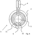
- Fig. 4 shows a plan view of the underside of the LED lamp. 1
- the base 6 is embedded in the cup-shaped metal cap 2.
- the leads 4 are guided around the channel 5 on the bottom.
- an LED lamp with a plurality of separately controlled LEDs usually includes more than the two feedthroughs shown here for plus and minus pole.
- the driver circuits for driving the LEDs are preferably not located in the hermetically sealed region of the luminaire shown here, but are arranged externally.
- Fig. 5 schematically shows a hermetically sealed LED lamp 1.
- This consists in this embodiment of an annular base 6 made of ceramic, on which a likewise annular metal cap with a plurality of windows 3, through which the light of the LEDs 10 emerges, is soldered.
- an image sensor 13 and a lens 14 is arranged in the central channel 5.
- Fig. 6 shows a schematic view of a medical instrument, namely the head piece of a dental drill.
- a hermetically sealed LED luminaire mounted directly on the head of the medical instrument 15 is a hermetically sealed LED luminaire according to the invention, the light of which is emitted directly via the windows 3 to the outside.
- Fig. 7 shows an alternative embodiment of a hermetically sealed LED light, which is not annular is formed, but was prepared by the method according to the invention.
- the LED lamp 17 comprises a base 18 made of a ceramic, in particular of aluminum oxide, on which by means of a gold-tin solder a metal cap 19, in particular made of stainless steel, is soldered.
- the base 18 is not embedded in the cap 19, but placed on the front side.
- the metal cap 19 is beveled edge. In the resulting gap, the solder 23 located there ensures a better connection of the components.
- a LED 22 designed as a chip is arranged, the light of which initially strikes an overlying converter 21, which is arranged beneath the window 20 designed as a lens.
- a window 20 made of glass is first prepared by this is melted into the metal cap 19.
- the metal cap 19 is still equipped with the converter 21.
- the metal cap 19 is soldered to the already equipped with the LED 22 socket 18.
Landscapes
- Health & Medical Sciences (AREA)
- Engineering & Computer Science (AREA)
- Physics & Mathematics (AREA)
- Life Sciences & Earth Sciences (AREA)
- General Engineering & Computer Science (AREA)
- Optics & Photonics (AREA)
- Oral & Maxillofacial Surgery (AREA)
- Animal Behavior & Ethology (AREA)
- General Health & Medical Sciences (AREA)
- Public Health (AREA)
- Veterinary Medicine (AREA)
- Microelectronics & Electronic Packaging (AREA)
- Dentistry (AREA)
- Epidemiology (AREA)
- Surgery (AREA)
- Biomedical Technology (AREA)
- Heart & Thoracic Surgery (AREA)
- Medical Informatics (AREA)
- Molecular Biology (AREA)
- Biophysics (AREA)
- Nuclear Medicine, Radiotherapy & Molecular Imaging (AREA)
- Pathology (AREA)
- Radiology & Medical Imaging (AREA)
- Astronomy & Astrophysics (AREA)
- General Physics & Mathematics (AREA)
- Manufacturing & Machinery (AREA)
- Multimedia (AREA)
- Led Device Packages (AREA)
- Arrangement Of Elements, Cooling, Sealing, Or The Like Of Lighting Devices (AREA)
- Non-Portable Lighting Devices Or Systems Thereof (AREA)
- Fastening Of Light Sources Or Lamp Holders (AREA)
- Endoscopes (AREA)
- Dental Tools And Instruments Or Auxiliary Dental Instruments (AREA)
Abstract
Description
- Die Erfindung betrifft eine hermetisch abgedichtete LED-Leuchte sowie ein Verfahren zur Herstellung einer hermetisch abgedichteten LED-Leuchte. Insbesondere betrifft die Erfindung eine LED-Leuchte, welche im medizinischen Bereich, also für ärztliche Geräte und Instrumente, verwendet wird.
- Im ärztlichen Bereich, insbesondere bei Geräten von Zahnärzten, finden vermehrt LED-Leuchten Verwendung, welche insbesondere auch Teil von ärztlichen Instrumenten sein können. Diese dienen Beleuchtungszwecken, beispielsweise des Ausleuchtens der Mundhöhle eines Patienten, dem Aufspüren von Defektstellen, etwa von Karies, wenn beispielsweise Licht einer bestimmten Wellenlänge, welches das Auffinden von Defektstellen erleichtert, emittiert wird, als Beleuchtung einer Kamera, insbesondere der eines Endoskops, sowie dem Aushärten von Füllmaterialen, etwa beim Aushärten von mittels UV-Licht aushärtbaren Kunststoffen.
- Typischerweise unterliegen derartige Leuchten hohen Belastungen, insbesondere müssen die meisten medizinischen Geräte hermetisch abgedichtet und in manchen Fällen sogar autoklavierbar sein.
- Die verwendeten Vorrichtungen sollten zudem langlebig sein und keine schädlichen Stoffe abgeben.
- Insbesondere bei zahnärztlichen Instrumenten sind Griffstücke bekannt, welche eine LED-Lichtquelle aufweisen. Die LED-Lichtquelle ist dabei zumeist in das Gehäuse des Griffstücks integriert und das von der LED-Lichtquelle abgestrahlte Licht wird mittels eines Lichtleiters zu einem Fenster im vorderen Bereich des Griffstücks geleitet, von wo aus dieses in den Mundraum abgestrahlt wird.
- Bekannte LED-Leuchten, welche beispielsweise mit einer polymeren Vergussmasse abgedichtet sind, sind in der Regel für einen Einsatz zumindest an der Außenseite eines derartigen ärztlichen Gerätes nicht hinreichend geeignet.
- Der Erfindung liegt demgegenüber die Aufgabe zugrunde, eine hermetisch abgedichtete LED-Leuchte bereitzustellen, welche gut in ein ärztliches Instrument integrierbar und den erhöhten Anforderungen im medizinischen Bereich, was Haltbarkeit und Dichtigkeit angeht, gewachsen ist.
- Die Aufgabe der Erfindung wird bereits durch eine hermetisch abgedichtete LED-Leuchte sowie ein Verfahren zum Herstellen einer hermetisch abgedichteten LED-Leuchte nach einem der unabhängigen Ansprüche gelöst.
- Bevorzugte Ausführungsformen und Weiterbildungen der Erfindung sind dem Gegenstand der jeweiligen Unteransprüche zu entnehmen.
- Die Erfindung betrifft eine hermetisch abgedichtete LED-Leuchte, also eine LED-Leuchte mit einem Gehäuse, welches zumindest flüssigkeitsdicht ist.
- Die LED-Leuchte umfasst einen Sockel mit einer Mehrzahl von LEDs.
- Vorzugsweise handelt es sich bei den LEDs um als Chip ausgebildete LEDs, welche direkt auf den Sockel gebondet sind.
- Derartige LED-Chips können LEDs mit hoher Leistung aufweisen, die Wärme lässt sich gut über den Sockel abführen und die Bauteile sind kompakt ausgebildet.
- Der Sockel ist aus einer Keramik ausgebildet. Insbesondere ist der Sockel aus einem Aluminiumoxid und/oder einem Aluminiumnitrid ausgebildet.
- Weiter weist die LED-Leuchte eine Metallkappe mit zumindest einem Fenster auf. Vorzugsweise weist die Metallkappe mehrere Fenster auf, welche jeweils den LEDs gegenüberliegen und durch die das Licht aus der LED-Leuchte austritt.
- Die Metallkappe ist auf den Sockel gelötet und die LED-Leuchte weist des Weiteren einen Kanal zum Einbringen eines elektrischen, optischen und/oder mechanischen Bauelements auf, welcher sich sowohl durch Sockel als auch durch Kappe erstreckt.
- Durch die Kombination eines Sockels aus Keramik mit einer aufgelöteten Metallkappe konnte ein Bauelement in Form einer LED-Leuchte bereitgestellt werden, welches trotz eines Kanals, der die Bauteile durchdringt, eine hohe Dichtigkeit aufweist.
- Der Kanal dient der Aufnahme eines elektrischen oder mechanischen Bauelements, welches insbesondere Teil eines verwendeten ärztlichen Gerätes ist.
- Beispielsweise kann in dem Kanal ein Bildsensor, insbesondere eine Kamera angeordnet sein, für welche die LED-Leuchte als Lichtquelle dient.
- Der Kanal kann dabei eine beliebige Form haben, insbesondere eine konische, kreiszylindrische oder auch eckige Form. Weiter ist denkbar, den Kanal gestuft auszubilden, beispielsweise indem Sockel und Kappe einen Kanal mit unterschiedlichem Durchmesser aufweisen. Diese Stufe kann sodann als Anschlag zum verbesserten Halten eines mechanischen oder elektrischen Bauelements verwendet werden.
- Bei einer bevorzugten Ausführungsform ist die LED-Leuchte ringförmig mit im Wesentlichen mittig angeordnetem Kanal ausgebildet.
- Die LEDs sind vorzugsweise über den Umfang des so gebildeten Rings verteilt. Die LED-Leuchte kann insbesondere 4 bis 10 LEDs aufweisen.
- Eine derartige Leuchte kann insbesondere auch am Kopfstück eines ärztlichen Instruments, beispielsweise auch eines Zahnarztbohrers angeordnet sein. Dabei kann die Antriebswelle des Bohrers und/oder der Bohrer selbst durch den Kanal ragen und die LEDs dienen insbesondere zur Ausleuchtung.
- Vorzugsweise umfasst die LED-Leuchte eine Mehrzahl von Fenstern, welche ringförmig verteilt sind.
- Bei einer Weiterbildung der Erfindung sind die Fenster als Linsen ausgebildet.
- Insbesondere kann über die Fenster das Licht der LEDs fokussiert werden.
- Bei einer bevorzugten Ausführungsform sind die Fenster jeweils in einen Kanal der Metallkappe eingelassen. Die Kanäle, in die die Fenster eingelassen sind, haben vorzugsweise eine Höhe zwischen 0,15 und 20 mm. Vorzugsweise reichen die Kanäle jeweils bis zum Sockel, d.h. unmittelbar angrenzend zum jeweiligen Kanal sind Metallkappe und Sockel verlötet.
- Es ist insbesondere vorgesehen, dass die Metallkappe vorzugsweise zylindrisch, insbesondere kreiszylindrisch ausgebildete Kanäle aufweist, in welche Glasfenster, insbesondere in Form von Linsen, eingeschmolzen sind.
- Für die Herstellung einer derartigen Metallkappe kann jeweils ein Stück eines Glasstabs in jeweils einen Kanal eingelegt werden. Durch ein Erwärmen schmilzt das Glas und es bildet sich aufgrund der Oberflächenspannung des Glases eine Linse aus.
- Bei einer Ausführungsvariante umfasst die LED-Leuchte eine Mehrzahl von Fenstern, wobei die Metallkappe angrenzend zu den Fenstern eine Einsenkung umfasst.
- Insbesondere umfasst die Metallkappe an der Oberseite eine Einsenkung, an welche ein Kanal angrenzt.
- Wird nunmehr ein Glasfenster in den Kanal eingeschmolzen, wobei sich eine Linse ausbildet, steht die Linse aufgrund der Einsenkung nicht über die Oberseite der Metallkappe hinaus, so dass, wenn die LED-Leuchte ohne weitere Schutzscheibe verwendet wird, die Fenster bei Berührung eines Gegenstandes nicht beschädigt werden, da die Metallkappe anstößt.
- Bei einer Ausführungsform der Erfindung ist in den Kanal unterhalb des Fensters ein Konverter eingelassen. Insbesondere kann ein Konverter mit einer Trägermatrix aus Silikon verwendet werden, in welchem fluoreszierende Partikel, beispielsweise Phosphor, YAG etc., eingebettet sind. Der Konverter lässt sich in den Kanal besonders einfach einbringen, etwa durch Einkleben. Die Verwendung eines Konverters mit einer Silikonmatrix resultiert in einer einfachen Herstellung und einer hohen Temperaturstabilität. Weiter ist auch die Verwendung von Konvertern mit anorganischer Matrix denkbar.
- Durch das Einschmelzen eines Glasfensters in einem Kanal, welches vorzugsweise möglichst dicht vor einem optional verwendeten Konverter angeordnet ist, kann eine LED-Leuchte mit großem Abstrahlwinkel bereitgestellt werden.
- Insbesondere kann der Abstrahlwinkel mehr als 85°, vorzugsweise mehr als 90° und besonders bevorzugt mehr als 94° betragen. Unter dem Abstrahlwinkel im Sinne der Erfindung wird der von seitlichen Punkten mit halber maximaler Lichtstärke eingeschlossene Winkel verstanden.
- Die Erfindung betrifft des Weiteren eine hermetisch abgedichtete LED-Leuchte, insbesondere eine solche Leuchte, wie sie vorstehend beschrieben wurde.
- Diese umfasst einen Sockel, vorzugsweise einen Sockel aus Keramik mit einer Mehrzahl von LEDs, welcher zumindest eine Kappe mit einer Mehrzahl von Fenstern aufweist, wobei die LED-Leuchte getrennt ansteuerbare LEDs verschiedener Lichtfarbe umfasst und wobei der Abstrahlwinkel des Lichts von zumindest zwei getrennt ansteuerbaren LEDs unterschiedlich ist.
- Die LED-Leuchte umfasst für verschiedene Verwendungen also LEDs in unterschiedlicher Lichtfarbe. Im Falle der Bereitstellung einer LED-Leuchte für den zahnärztlichen Bereich können dies beispielsweise Leuchten mit im Wesentlichen weißem Licht zum Ausleuchten der Mundhöhle, LEDs spezieller Lichtfarbe zum Erkennen von Karies oder Zahnbelegen sowie LEDs, welche UV-Licht emittieren, sein, welche dem Aushärten von Kunststoff dienen. Diese sind getrennt ansteuerbar. Hierzu umfasst der Sockel eine Mehrzahl elektrischer Durchführungen für die jeweiligen LEDs oder LED-Gruppen.
- Es ist insbesondere vorgesehen, dass zumindest eine LED einen Abstrahlwinkel von weniger als 60° und eine andere LED einen Abstrahlwinkel von mehr als 70° aufweist. Weiter ist insbesondere vorgesehen, dass sich der Abstrahlwinkel von mindestens zwei LEDs um zumindest 10°, vorzugsweise um zumindest 20° unterscheidet.
- Hierzu werden vorzugsweise Fenster verwendet, welche als Linsen mit unterschiedlicher Brennweite und/oder mit unterschiedlichem Öffnungswinkel ausgebildet sind.
- Im Falle des Einschmelzens von Glas können diese beispielsweise durch eine unterschiedliche Form des Kanals und/oder durch ein unterschiedliches Glas bereitgestellt werden.
- Beispielsweise für LEDs, die UV-Licht emittieren, kann eine Fokussierung des Lichtes und das Abstrahlen mit geringem Abstrahlwinkel sinnvoll sein, wohingegen LEDs zum Ausleuchten des Mundraums einen breiteren Abstrahlwinkel aufweisen.
- Die LED-Leuchte ist insbesondere Teil eines ärztlichen Instruments, wobei die LED-Leuchte derart in das ärztliche Instrument eingelassen ist, dass die LED-Leuchte direkt nach außen abstrahlt. Hierunter wird verstanden, dass das Licht nicht über einen Lichtleiter zu einem Austrittsfenster geleitet wird. Es ist aber denkbar, dass in Emissionsrichtung noch ein weiteres Fenster oder eine Schutzscheibe vorgesehen ist. Vorzugsweise bildet die Metallkappe im Bereich der Leuchte samt ihren Fenstern aber den Abschluss des ärztlichen Instruments.
- Die Erfindung betrifft des Weiteren ein Verfahren zum Herstellen einer LED-Leuchte, insbesondere ein Verfahren zum Herstellen einer LED-Leuchte, wie sie vorstehend beschrieben wurde.
- Dabei wird zunächst ein Sockel aus Keramik mit zumindest einer LED bestückt, insbesondere mit einer LED, welche auf einem Chip angeordnet ist. Sodann wird mittels eines Metall-Lots eine Metallkappe auf den Sockel gelötet.
- Vorzugsweise wird bereits vor dem Verlöten die Metallkappe mit zumindest einem Fenster versehen, insbesondere durch Aufschmelzen eines Glases in jeweils einem Kanal der Metallkappe.
- Denkbar ist auch, das zumindest eine Fenster als Druckeinglasung auszugestalten.
Die aus Glas hergestellten Fenster sind vorzugsweise aus einem Material mit guter chemischer Beständigkeit, insbesondere aus einem Silikatglas, beispielsweise aus einem Borosilikatglas, ausgebildet. - Es sind sodann nur noch die Elemente Metallkappe nebst Fenster und Sockel aus Keramik, zusammenzufügen.
- Es hat sich gezeigt, dass durch Verwendung eines geeigneten Lots, insbesondere durch Verwendung eines Gold-Zinn-Lots eine stabile und hermetisch dichte Verbindung erzielt werden kann, ohne dass die LED-Leuchte derart heiß wird, dass die LED, insbesondere die als Chip ausgebildete LED, beschädigt wird.
- Durch die Verwendung eines Gold-Zinn-Lots kann ein autoklavierbares Gehäuse bereit gestellt werden.
- Weiter ist diese Verbindung auch bei eventuell folgenden Lötprozessen, insbesondere einem Reflowprozess oder bei der Verwendung eines Zinn-Silber-Kupfer-Lots beständig.
- Vorzugsweise wird ein Lot, insbesondere ein Gold-Zinn-Lot verwendet, dessen Schmelztemperatur bei unter 300°C, besonders bevorzugt bei unter 280°C, liegt.
- Weiter weist vorzugsweise der Sockel aus Keramik elektrische Durchführungen auf, welche durch einen Metall-Lot hermetisch verriegelt sind.
- Auch diese Durchführungen, über die die LEDs kontaktiert sind, werden vorzugsweise vor dem Verlöten von Sockel und Metallkappe ausgebildet.
- Bei einer Weiterbildung der Erfindung wird zumindest die Metallkappe mit einer Beschichtung versehen, insbesondere mit einer nickel- und/oder goldhaltigen Beschichtung. Insbesondere wird eine Beschichtung aus Hartgold aufgebracht.
- Die Metallkappe besteht vorzugsweise aus einem Edelstahl, insbesondere aus einem Edelstahl mit einem geringen Wärmeausdehnungskoeffizienten. So ist die Metallkappe an den niedrigen Wärmeausdehnungskoeffizienten der Keramik angepasst. Insbesondere hat das Material der Metallkappe einen thermischen Wärmeausdehnungskoeffizienten α bei Raumtemperatur von weniger als 15, bevorzugt weniger als 8 und besonders bevorzugt weniger als 5 ppm/K.
- Insbesondere besteht die Metallkappe aus einem ferritischen Edelstahl.
- Bei einer Ausführungsform der Erfindung weichen die thermischen Ausdehnungskoeffizienten α von Metallkappe und dem Material der Fenster weniger als 5 ppm/K, vorzugsweise weniger als 1 ppm/K voneinander ab. Gleiches gilt vorzugsweise für die thermischem Ausdehnungskoeffizienten von Sockel und Metallkappe.
- Als Lot für die Durchführungen der Kontaktierung der LEDs kann beispielsweise ein Gold-Zinn-, ein Zinn-, ein Kupfer- oder Silber-Lot verwendet werden.
- Durch die Erfindung konnte eine hermetisch abgedichtete LED-Leuchte bereitgestellt werden, welche sogar autoklavierbar ist.
- Der Gegenstand der Erfindung soll im Folgenden bezugnehmend auf Ausführungsbeispiele näher erläutert werden.
-
Fig. 1 zeigt eine Draufsicht auf ein Ausführungsbeispiel einer hermetisch abgedichteten LED-Leuchte. -
Fig. 2 zeigt eine Schnittansicht derFig. 1 . -
Fig. 3 zeigt eine Detaildarstellung derFig. 2 . -
Fig. 4 zeigt eine Draufsicht auf die Unterseite. -
Fig. 5 zeigt in einer schematischen Darstellung die Verwendung der erfindungsgemäßen hermetisch abgedichteten LED-Leuchte in Verbindung mit einem Drittsensor. -
Fig. 6 zeigt eine schematische Ansicht eines ärztlichen Instrumentes, in welches eine erfindungsgemäße, hermetisch abgedichtete LED-Leuchte eingebaut ist. -
Fig. 7 zeigt ein anderes Ausführungsbeispiel einer hermetisch abgedichteten LED-Leuchte, welche nicht ringförmig ausgebildet ist. -
Fig. 1 zeigt in einer Draufsicht ein Ausführungsbeispiel einer erfindungsgemäßen, hermetisch abgedichteten LED-Leuchte 1. - Die LED-Leuchte 1 ist in diesem Ausführungsbeispiel ringförmig ausgebildet. Zu erkennen ist auf der Oberseite die Metallkappe 2, welche eine Mehrzahl von Fenstern 3 aufweist, durch die das Licht der darunterliegenden LEDs abgestrahlt wird.
- Über die Zuleitung 4 kann die LED-Leuchte 1 angeschlossen werden.
- Die in diesem Ausführungsbeispiel dargestellten sechs Fenster 3 sind über den Umfang der LED-Leuchte 1 verteilt.
- Weiter zu erkennen ist ein mittig angeordneter Kanal 5 mit kreisförmigem Querschnitt, welcher der Aufnahme eines elektrischen, optischen oder mechanischen Bauelements dient.
-
Fig. 2 zeigt eine Schnittansicht der inFig. 1 dargestellten LED-Leuchte. - Zu erkennen ist, dass die Metallkappe 2, welche aus einem Edelstahl besteht, topfförmig ausgebildet ist.
- Ein Sockel 6 aus einer Keramik, insbesondere aus Aluminiumoxid, ist von der Unterseite in die topfförmige Metallkappe 2 eingelassen und mittels eines Gold-Zinn-Lots mit der Metallkappe verlötet.
- Der plattenförmige Sockel 6 ist ebenfalls ringförmig ausgebildet, so dass der Kanal 5 sowohl durch den Sockel 6 als auch durch die Metallkappe 2 verläuft.
- Der Sockel 6 besitzt Durchführungen (nicht dargestellt), über welche über die Zuleitung 4 Strom zur Ansteuerung der LEDs auf die Oberseite geleitet wird.
-
Fig. 3 zeigt eine Detaildarstellung derFig. 2 , und zwar den Bereich, in welchem ein Fenster 3 angeordnet ist. - Zu erkennen ist, dass der Sockel 6 des Fensters 3 mit einer LED 10 bestückt ist. Die LED 10 ist als Chip ausgebildet. Es handelt sich insbesondere um ein SMD- (Surface Mounted Device) Bauelement.
- Auf der Oberseite des Sockels 6 können sich Zuleitungen, etwa in Form von Flachleiterbahnen, zur Kontaktierung der LED 10 befinden (nicht dargestellt).
- Zu erkennen ist ferner, dass das Fenster 3 linsenförmig ausgebildet ist.
- Das Fenster 3 ist in einen Kanal 7 eingelassen, welcher seinerseits in die Metallkappe 2 eingebracht ist.
- Die linsenförmige Ausgestaltung des Fensters 3 kommt durch die Oberflächenspannung des Glases zustande, indem dieses hergestellt wird, indem ein Glasstab in den Kanal 7 eingelegt und sodann aufgeschmolzen wird.
- Oberhalb des Kanals 7 befindet sich eine randseitige Einsenkung 8.
- Aufgrund der Einsenkung 8 ragt das linsenförmig ausgestaltete Fenster 3 nicht hervor.
- Optional kann, je nach gewünschter Lichtfarbe, in den Kanal 7 ein Konverter 9 eingebracht sein. Es handelt sich insbesondere um einen Konverter mit einer Silikonmatrix, welcher in den Kanal 7 eingeklebt wird.
- Zu erkennen ist ferner, dass der Sockel 6 mit seiner Oberseite auf die Unterseite der topfförmigen Metallkappe 2 gelötet ist.
- Randseitig ist in diesem Ausführungsbeispiel der Sockel 6 von der Metallkappe 2 beabstandet.
- Durch das Verlöten von Sockel 6 und Metallkappe 2 sowie durch das eingeschmolzene Fenster 3 wird eine hermetische Abdichtung der LED 10 bereitgestellt.
- Kontaktführungen im Sockel 6 sind vorzugsweise ebenfalls mit einem Lot aufgefüllt.
- Für eine Montage der erfindungsgemäßen LED-Leuchte wird zunächst die Metallkappe mit den eingeschmolzenen Fenstern hergestellt und separat hiervon wird der Sockel 6 mit den LEDs 10 bestückt.
- Diese beiden Hauptkomponenten werden sodann mittels eines Gold-Zinn-Lots mit einer Schmelztemperatur von unter 340 °C, bevorzugt unter 325 °C, besonders bevorzugt unter 300 °C miteinander verlötet.
- Das erfindungsgemäße Verfahren eignet sich nicht nur für die hier dargestellte ringförmige LED-Leuchte, sondern auch für andere Arten von Leuchten, also insbesondere auch solche ohne einen mittigen Kanal.
-
Fig. 4 zeigt eine Draufsicht von der Unterseite der LED-Leuchte 1. - Zu erkennen ist der ringförmige Sockel 6, welcher in diesem Ausführungsbeispiel die Durchführungen 11 und 12 aufweist, mittels derer die LEDs auf der Oberseite angesteuert werden.
- Der Sockel 6 ist in die topfförmige Metallkappe 2 eingelassen.
- Zu erkennen ist ferner der mittige Kanal 5, in welchen ein elektrisches, optisches oder mechanisches Bauelement angeordnet sein kann.
- Die Zuleitungen 4 werden um den Kanal 5 auf der Unterseite herumgeführt.
- Es versteht sich, dass eine LED-Leuchte mit mehreren, getrennt voneinander angesteuerten LEDs in der Regel mehr als die hier dargestellten zwei Durchführungen für Plus- und Minuspol umfasst. Die Treiberschaltungen zum Ansteuern der LEDs befinden sich vorzugsweise nämlich nicht im hermetisch abgedichteten Bereich der hier dargestellten Leuchte, sondern sind extern angeordnet.
-
Fig. 5 zeigt schematisch eine hermetisch abgedichtete LED-Leuchte 1. Diese besteht auch in diesem Ausführungsbeispiel aus einem ringförmigen Sockel 6 aus Keramik, auf den eine ebenfalls ringförmige Metallkappe mit einer Mehrzahl von Fenstern 3, durch die das Licht der LEDs 10 austritt, aufgelötet ist. - In dem mittigen Kanal 5 ist ein Bildsensor 13 sowie eine Linse 14 angeordnet.
-
Fig. 6 zeigt eine schematische Ansicht eines ärztlichen Instruments, und zwar des Kopfstücks eines zahnärztlichen Bohrers. - Zu sehen ist eine Aufnahme 16, in welche die Bohrer eingesetzt werden und sodann mit einer Antriebswelle verbunden sind.
- Direkt auf den Kopf des ärztlichen Instruments 15 montiert ist eine erfindungsgemäße, hermetisch abgedichtete LED-Leuchte, deren Licht direkt über die Fenster 3 nach außen abgestrahlt wird.
- Unter anderem aufgrund der guten Dichtigkeit des Gehäuses der erfindungsgemäßen Leuchte ist es nicht notwendig, die LED-Leuchte im Gehäuse des ärztlichen Instruments anzuordnen und das abgestrahlte Licht über Lichtleiter nach vorne zu führen.
-
Fig. 7 zeigt eine Ausführungsvariante einer hermetisch abgedichteten LED-Leuchte, welche nicht ringförmig ausgebildet ist, aber mit dem erfindungsgemäßen Verfahren hergestellt wurde. - Die LED-Leuchte 17 umfasst einen Sockel 18 aus einer Keramik, insbesondere aus Aluminiumoxid, auf welchen mittels eines Gold-Zinn-Lots eine Metallkappe 19, insbesondere aus Edelstahl, aufgelötet ist.
- Der Sockel 18 ist nicht in die Kappe 19 eingelassen, sondern stirnseitig aufgesetzt.
- Die Metallkappe 19 ist randseitig abgeschrägt. In dem dadurch entstehenden Spalt sorgt das dort befindliche Lot 23 für eine bessere Verbindung der Bauteile.
- Im Inneren der hermetisch abgedichteten LED-Leuchte 19 ist eine als Chip ausgebildete LED 22 angeordnet, deren Licht zunächst auf einen darüberliegenden Konverter 21 trifft, welcher unterhalb des als Linse ausgebildeten Fensters 20 angeordnet ist.
- Auch zum Herstellen dieser LED-Leuchte 17 wird zunächst ein Fenster 20 aus Glas hergestellt, indem dieses in die Metallkappe 19 eingeschmolzen wird. Optional wird die Metallkappe 19 noch mit dem Konverter 21 bestückt.
- Sodann wird die Metallkappe 19 mit dem bereits mit der LED 22 bestückten Sockel 18 verlötet.
-
- 1
- LED-Leuchte
- 2
- Metallkappe
- 3
- Fenster
- 4
- Zuleitung
- 5
- Kanal
- 6
- Sockel
- 7
- Kanal
- 8
- Einsenkung
- 9
- Konverter
- 10
- LED
- 11
- Durchführung
- 12
- Durchführung
- 13
- Bildsensor
- 14
- Linse
- 15
- ärztliches Instrument
- 16
- Aufnahme
- 17
- LED-Leuchte
- 18
- Sockel
- 19
- Metallkappe
- 20
- Fenster
- 21
- Konverter
- 22
- LED
- 23
- Lot
Claims (15)
- Hermetisch abgedichtete LED-Leuchte, umfassend einen Sockel mit einer Mehrzahl von LEDs, welcher aus Keramik ausgebildet ist, sowie zumindest eine Metallkappe mit zumindest einem Fenster, welche auf den Sockel gelötet ist, und wobei die LED-Leuchte einen Kanal zum Einbringen eines elektrischen, optischen oder mechanischen Bauelements aufweist, welcher sich durch Sockel und Metallkappe erstreckt.
- Hermetisch abgedichtete LED-Leuchte nach dem vorstehenden Anspruch, dadurch gekennzeichnet, dass die LED-Leuchte ringförmig mit mittig angeordnetem Kanal ausgebildet ist.
- Hermetisch abgedichtete LED-Leuchte nach dem vorstehenden Anspruch, dadurch gekennzeichnet, dass die LED-Leuchte eine Mehrzahl von Fenstern umfasst, welche ringförmig verteilt sind.
- Hermetisch abgedichtete LED-Leuchte nach dem vorstehenden Anspruch, dadurch gekennzeichnet, dass die Fenster als Linsen ausgebildet sind.
- Hermetisch abgedichtete LED-Leuchte nach einem der vorstehenden Ansprüche, dadurch gekennzeichnet, dass die LED-Leuchte eine Mehrzahl von Fenstern umfasst, welche jeweils in einen Kanal der Metallkappe eingelassen sind.
- Hermetisch abgedichtete LED-Leuchte nach einem der vorstehenden Ansprüche, dadurch gekennzeichnet, dass die LED-Leuchte eine Mehrzahl von Fenstern umfasst, wobei die Metallkappe angrenzend zu den Fenstern eine Einsenkung umfasst.
- Hermetisch abgedichtete LED-Leuchte nach Anspruch 5 oder 6, dadurch gekennzeichnet, dass in den Kanal unterhalb des Fensters ein Konverter eingelassen ist.
- Hermetisch abgedichtete LED-Leuchte, insbesondere nach einem der vorstehenden Ansprüche, umfassend einen Sockel mit einer Mehrzahl von LEDs, welcher, zumindest eine Kappe, insbesondere eine Metallkappe mit einer Mehrzahl von Fenstern aufweist.
- Hermetisch abgedichtete LED-Leuchte, insbesondere nach einem der vorstehenden Ansprüche, wobei die Leuchte getrennt ansteuerbare LEDs verschiedener Lichtfarbe umfasst, wobei der Abstrahlwinkel des Lichts von zumindest zwei getrennt ansteuerbaren LEDs unterschiedlich ist.
- Hermetisch abgedichtete LED-Leuchte nach einem der vorstehenden Ansprüche, dadurch gekennzeichnet, dass die Fenster als Linsen ausgebildet sind, welche eine unterschiedliche Brennweite und/oder einen unterschiedlichen Öffnungswinkel aufweisen.
- Ärztliches Instrument, umfassend eine hermetisch abgedichtete LED-Leuchte nach einem der vorstehenden Ansprüche, wobei die LED-Leuchte derart in das ärztliche Instrument eingelassen ist, dass LED-Leuchte direkt nach außen abstrahlt.
- Verfahren zum Herstellen einer hermetisch abgedichteten LED-Leuchte, insbesondere einer LED-Leuchte nach einem der vorstehenden Ansprüche, wobei zunächst ein Sockel aus Keramik mit zumindest einer LED bestückt wird und sodann eine Metallkappe, mittels eines Metalllots auf den Sockel gelötet wird, insbesondere mittels eines Gold-Zinn-Lots.
- Verfahren zum Herstellen einer hermetisch abgedichteten LED-Leuchte nach einem der vorstehenden Ansprüche, dadurch gekennzeichnet, dass die Metallkappe vor dem Verlöten von Metallkappe und Sockel mit Fenstern versehen wird.
- Verfahren zum Herstellen einer hermetisch abgedichteten LED-Leuchte nach dem vorstehenden Anspruch, dadurch gekennzeichnet, dass die Fenster durch Aufschmelzen eines Glases in jeweils einem Kanal der Metallkappe eingebracht werden.
- Verfahren zum Herstellen einer hermetisch abgedichteten LED-Leuchte nach einem der vorstehenden Ansprüche, dadurch gekennzeichnet, dass die Metallkappe beschichtet wird, insbesondere mit einer nickel- und/oder goldhaltigen Beschichtung.
Applications Claiming Priority (2)
| Application Number | Priority Date | Filing Date | Title |
|---|---|---|---|
| DE102015103331.3A DE102015103331B4 (de) | 2015-03-06 | 2015-03-06 | Hermetisch abgedichtete LED-Leuchte, Verfahren zur Herstellung einer hermetisch abgedichteten LED-Leuchte sowie ärztliches Instrument umfassend eine hermetisch abgedichtete LED-Leuchte |
| DE102015103507 | 2015-03-10 |
Publications (2)
| Publication Number | Publication Date |
|---|---|
| EP3064166A1 true EP3064166A1 (de) | 2016-09-07 |
| EP3064166B1 EP3064166B1 (de) | 2018-07-04 |
Family
ID=55527752
Family Applications (1)
| Application Number | Title | Priority Date | Filing Date |
|---|---|---|---|
| EP16157312.6A Active EP3064166B1 (de) | 2015-03-06 | 2016-02-25 | Hermetisch abgedichtete led-leuchte sowie verfahren zur herstellung einer hermetisch abgedichteten led-leuchte |
Country Status (5)
| Country | Link |
|---|---|
| US (2) | US10890318B2 (de) |
| EP (1) | EP3064166B1 (de) |
| JP (3) | JP6566895B2 (de) |
| KR (1) | KR102034919B1 (de) |
| CN (2) | CN105937708A (de) |
Families Citing this family (4)
| Publication number | Priority date | Publication date | Assignee | Title |
|---|---|---|---|---|
| DE102017212030A1 (de) * | 2017-07-13 | 2019-01-17 | Tridonic Jennersdorf Gmbh | LED/LD-Beleuchtungsvorrichtung mit neuartiger Remote-Leuchtstoff-Konfiguration und Verfahren zur Herstellung einer solchen |
| DE102017127723A1 (de) * | 2017-11-23 | 2019-05-23 | Schott Ag | Autoklavierbares medizinisches Gerät sowie Betätigungseinrichtung für ein autoklavierbares medizinisches Gerät |
| EP4268759B1 (de) | 2018-10-29 | 2025-01-01 | Stryker Corporation | System zur durchführung von wirbelsäulenoperationen und aufrechterhaltung eines flüssigkeitsvolumens an einer operationsstelle |
| CN114587239A (zh) * | 2022-04-11 | 2022-06-07 | 天津恩泽生医疗科技有限公司 | 一种耐高温硬管内窥镜 |
Citations (2)
| Publication number | Priority date | Publication date | Assignee | Title |
|---|---|---|---|---|
| EP2548530A1 (de) * | 2011-07-19 | 2013-01-23 | W & H Dentalwerk Bürmoos GmbH | Beleuchtungsvorrichtung für ein medizinisches, insbesondere dentales, Instrument |
| EP2842513A1 (de) * | 2013-08-28 | 2015-03-04 | W & H Dentalwerk Bürmoos GmbH | Beleuchtungsvorrichtung für ein medizinisches, insbesondere dentales, Instrument |
Family Cites Families (51)
| Publication number | Priority date | Publication date | Assignee | Title |
|---|---|---|---|---|
| FR2568443B1 (fr) * | 1984-07-27 | 1986-11-14 | Cepe | Boitier a fermeture a froid supportant les hautes temperatures |
| US5531664A (en) * | 1990-12-26 | 1996-07-02 | Olympus Optical Co., Ltd. | Bending actuator having a coil sheath with a fixed distal end and a free proximal end |
| WO1995015060A1 (en) | 1993-11-22 | 1995-06-01 | Apollo Camera, L.L.C. | Single sensor video imaging system and method using sequential color object illumination |
| JPH09140664A (ja) | 1995-11-20 | 1997-06-03 | Osada Res Inst Ltd | 歯科用口腔内観察カメラ |
| WO1998014527A1 (en) | 1996-10-02 | 1998-04-09 | Ormco Corporation | Metal to ceramic attachment in dental appliances |
| US6547721B1 (en) * | 1998-08-07 | 2003-04-15 | Olympus Optical Co., Ltd. | Endoscope capable of being autoclaved |
| JP2000316874A (ja) * | 1999-05-07 | 2000-11-21 | Morita Mfg Co Ltd | 照明機構付き歯科用器具 |
| US6796939B1 (en) * | 1999-08-26 | 2004-09-28 | Olympus Corporation | Electronic endoscope |
| JP3121812B1 (ja) * | 1999-10-20 | 2001-01-09 | 株式会社ナカニシ | 歯科・医科用器具の照明装置 |
| JP2003163382A (ja) | 2001-11-29 | 2003-06-06 | Matsushita Electric Ind Co Ltd | 受光素子または発光素子用パッケージ |
| US7775685B2 (en) * | 2003-05-27 | 2010-08-17 | Cree, Inc. | Power surface mount light emitting die package |
| JP3668480B2 (ja) * | 2003-03-06 | 2005-07-06 | オリンパス株式会社 | 撮像装置 |
| JP4056930B2 (ja) * | 2003-05-27 | 2008-03-05 | 株式会社モリタ製作所 | 医療用光照射装置 |
| JP4418202B2 (ja) * | 2003-10-06 | 2010-02-17 | オリンパス株式会社 | 内視鏡 |
| US7195482B2 (en) | 2003-12-30 | 2007-03-27 | Ultradent Products, Inc. | Dental curing device having a heat sink for dissipating heat |
| JP2005215213A (ja) * | 2004-01-28 | 2005-08-11 | Pentax Corp | レンズ接合体の製造方法、レンズ接合体および内視鏡 |
| US7762950B2 (en) * | 2004-03-25 | 2010-07-27 | Olympus Corporation | Endoscope |
| JP4606954B2 (ja) * | 2004-07-15 | 2011-01-05 | Toto株式会社 | 光レセプタクル用フェルール保持部材及びその製造方法並びにそれを用いた光レセプタクル |
| JP4917436B2 (ja) * | 2004-10-25 | 2012-04-18 | オリンパス株式会社 | 内視鏡装置 |
| DE202005002341U1 (de) | 2005-02-14 | 2005-06-02 | Gutmann, Max | UV-LED Lampe zur Sichtbarmachung von Zahnbelägen |
| JP4652843B2 (ja) * | 2005-02-21 | 2011-03-16 | オリンパスメディカルシステムズ株式会社 | 内視鏡 |
| DE202005020300U1 (de) | 2005-12-27 | 2006-02-16 | Chou, Peter | Steuerschaltung zum Verändern der Helligkeit und der Farbe einer Beleuchtungsvorrichtung mit Licht emittierenden Dioden |
| JP5130680B2 (ja) | 2006-03-02 | 2013-01-30 | 日亜化学工業株式会社 | 半導体装置およびその形成方法 |
| JP2007311325A (ja) * | 2006-04-17 | 2007-11-29 | Citizen Electronics Co Ltd | 導光板及びその製造方法とその導光板を用いたバックライトユニット |
| DE102007022605B4 (de) | 2006-05-24 | 2018-06-21 | Osram Gmbh | Farblich durchstimmbares Beleuchtungssystem zur abbildenden Beleuchtung |
| EP1870022B1 (de) * | 2006-06-22 | 2016-05-11 | W & H Dentalwerk Bürmoos GmbH | Medizinischer Handgriff mit Beleuchtungsvorrichtung und Verfahren zur Herstellung |
| US8269828B2 (en) * | 2006-12-22 | 2012-09-18 | Perceptron, Inc. | Thermal dissipation for imager head assembly of remote inspection device |
| CN201062739Y (zh) * | 2007-05-09 | 2008-05-21 | 常熟鸿邦新能源有限公司 | 组合式路灯结构 |
| DE102008033556A1 (de) * | 2008-03-14 | 2009-09-17 | Kaltenbach & Voigt Gmbh | Lichtquelle für ein zahnmedizinisches Gerät |
| JP5223447B2 (ja) | 2008-05-12 | 2013-06-26 | 日亜化学工業株式会社 | 半導体発光装置 |
| US8390193B2 (en) * | 2008-12-31 | 2013-03-05 | Intematix Corporation | Light emitting device with phosphor wavelength conversion |
| US8328381B2 (en) * | 2009-02-25 | 2012-12-11 | Black & Decker Inc. | Light for a power tool and method of illuminating a workpiece |
| JP5384970B2 (ja) * | 2009-02-25 | 2014-01-08 | オリンパス株式会社 | アダプタ式内視鏡 |
| JP5186464B2 (ja) * | 2009-11-04 | 2013-04-17 | 株式会社モリタ製作所 | 医療用ハンドピース |
| JP2011100866A (ja) * | 2009-11-06 | 2011-05-19 | Toshiba Corp | リードを有する薄膜基板及び薄膜基板の接続方法 |
| DE202010000518U1 (de) | 2010-03-31 | 2011-08-09 | Turck Holding Gmbh | Lampe mit einer in einem hermetisch verschlossenen Gehäuse angeordneten LED |
| JP5716627B2 (ja) * | 2011-10-06 | 2015-05-13 | オムロン株式会社 | ウエハの接合方法及び接合部の構造 |
| EP2668892B1 (de) * | 2011-10-27 | 2016-01-06 | Olympus Corporation | Endoskop |
| CN102628554A (zh) * | 2012-03-22 | 2012-08-08 | 浙江英特来光电科技有限公司 | 一种三通道共极式透镜结构的led灯 |
| JP2013251384A (ja) | 2012-05-31 | 2013-12-12 | Seika Sangyo Kk | 発光装置 |
| WO2014010140A1 (ja) * | 2012-07-11 | 2014-01-16 | パナソニック株式会社 | 窒化物半導体発光装置 |
| KR101373710B1 (ko) | 2012-12-12 | 2014-03-13 | (주)포인트엔지니어링 | 엘이디 금속기판 패키지 및 그 제조방법 |
| US9133990B2 (en) * | 2013-01-31 | 2015-09-15 | Dicon Fiberoptics Inc. | LED illuminator apparatus, using multiple luminescent materials dispensed onto an array of LEDs, for improved color rendering, color mixing, and color temperature control |
| CN103162236A (zh) * | 2013-03-28 | 2013-06-19 | 苏州百纳思光学科技有限公司 | 一种用于多芯片封装大功率led路灯的自由曲面透镜 |
| JP2015002824A (ja) | 2013-06-20 | 2015-01-08 | 株式会社中央技研 | 口腔医療用照明器具 |
| EP2815719B1 (de) | 2013-06-21 | 2018-10-03 | Kerr Corporation | Zahnmedizinische Lichthärtevorrichtung |
| JP5891208B2 (ja) * | 2013-08-13 | 2016-03-22 | Hoya株式会社 | 内視鏡用照明光学系 |
| CN203686834U (zh) * | 2014-01-26 | 2014-07-02 | 中山市帝光汽配实业有限公司 | 一种led汽车前照灯 |
| JP2015176960A (ja) * | 2014-03-14 | 2015-10-05 | 株式会社東芝 | 発光装置 |
| JP6302762B2 (ja) * | 2014-06-23 | 2018-03-28 | スタンレー電気株式会社 | 発光装置および照明装置 |
| JP6326561B1 (ja) * | 2016-06-27 | 2018-05-16 | オリンパス株式会社 | 内視鏡、内視鏡の製造方法 |
-
2016
- 2016-02-25 EP EP16157312.6A patent/EP3064166B1/de active Active
- 2016-03-03 KR KR1020160025657A patent/KR102034919B1/ko not_active Expired - Fee Related
- 2016-03-04 CN CN201610125274.2A patent/CN105937708A/zh active Pending
- 2016-03-04 CN CN202111351477.0A patent/CN114017688A/zh active Pending
- 2016-03-04 US US15/060,866 patent/US10890318B2/en active Active
- 2016-03-04 JP JP2016042331A patent/JP6566895B2/ja active Active
-
2017
- 2017-06-23 JP JP2017123344A patent/JP2017162843A/ja active Pending
-
2020
- 2020-10-30 JP JP2020183100A patent/JP6985485B2/ja active Active
- 2020-11-24 US US17/103,217 patent/US11933485B2/en active Active
Patent Citations (2)
| Publication number | Priority date | Publication date | Assignee | Title |
|---|---|---|---|---|
| EP2548530A1 (de) * | 2011-07-19 | 2013-01-23 | W & H Dentalwerk Bürmoos GmbH | Beleuchtungsvorrichtung für ein medizinisches, insbesondere dentales, Instrument |
| EP2842513A1 (de) * | 2013-08-28 | 2015-03-04 | W & H Dentalwerk Bürmoos GmbH | Beleuchtungsvorrichtung für ein medizinisches, insbesondere dentales, Instrument |
Non-Patent Citations (1)
| Title |
|---|
| SCHOTT AG: "Die erste ringförmige autoklavierbare High Brightness LED von SCHOTT", 9 February 2015 (2015-02-09), www.schott.com, XP055290210, Retrieved from the Internet <URL:http://www.schott.com/newsfiles/com/013_2015_schott-ring-leds-for-dental-and-medical-applications_de_final.pdf> [retrieved on 20160721] * |
Also Published As
| Publication number | Publication date |
|---|---|
| JP6985485B2 (ja) | 2021-12-22 |
| JP2016164880A (ja) | 2016-09-08 |
| US11933485B2 (en) | 2024-03-19 |
| KR102034919B1 (ko) | 2019-10-21 |
| US20160258582A1 (en) | 2016-09-08 |
| US10890318B2 (en) | 2021-01-12 |
| EP3064166B1 (de) | 2018-07-04 |
| KR20160108199A (ko) | 2016-09-19 |
| CN105937708A (zh) | 2016-09-14 |
| CN114017688A (zh) | 2022-02-08 |
| US20210080100A1 (en) | 2021-03-18 |
| JP2017162843A (ja) | 2017-09-14 |
| JP2021028913A (ja) | 2021-02-25 |
| JP6566895B2 (ja) | 2019-08-28 |
Similar Documents
| Publication | Publication Date | Title |
|---|---|---|
| DE69937544T2 (de) | Led-modul und leuchte | |
| EP3064166B1 (de) | Hermetisch abgedichtete led-leuchte sowie verfahren zur herstellung einer hermetisch abgedichteten led-leuchte | |
| EP2254499B1 (de) | Lichtquelle für ein zahnmedizinisches gerät | |
| DE3315675C2 (de) | ||
| EP2734142B1 (de) | Beleuchtungsvorrichtung für ein medizinisches, insbesondere dentales, instrument | |
| DE60318780T2 (de) | Lichtbestrahlungsgerät | |
| DE102011005597A1 (de) | Leuchtvorrichtung | |
| EP2264796A2 (de) | Weisse LED mit kegelfoermigem Reflektor und planaren Facetten | |
| WO2013139624A1 (de) | Optoelektronischer halbleiterchip und scheinwerfer mit einem solchen halbleiterchip | |
| WO2011138257A1 (de) | ELEKTRONIKGEHÄUSE FÜR EINE LAMPE, HALBLEITERLAMPE UND VERFAHREN ZUM VERGIEßEN EINES ELEKTRONIKGEHÄUSES FÜR EINE LAMPE | |
| EP1843080A3 (de) | Halbleiter-Strahlungsquelle | |
| DE102015103331B4 (de) | Hermetisch abgedichtete LED-Leuchte, Verfahren zur Herstellung einer hermetisch abgedichteten LED-Leuchte sowie ärztliches Instrument umfassend eine hermetisch abgedichtete LED-Leuchte | |
| AT12749U1 (de) | Leiterplattenelement mit wenigstens einer led | |
| DE102014214603A1 (de) | Halbleiterlampe | |
| EP2955740B1 (de) | Lampe und adapter für eine lampe | |
| WO2011127902A1 (de) | Lichtleitsystem | |
| DE102014205470B4 (de) | Leuchtvorrichtung mit CoB-Bereich | |
| DE102007007258A1 (de) | Leuchtmittel | |
| EP2216592A2 (de) | Lampe | |
| EP3651680B1 (de) | Led/laser-beleuchtungsvorrichtung mit getrennter leuchtstoffkonfiguration und verfahren zur herstellung einer solchen | |
| WO2013056916A2 (de) | Auflage für eine leuchtvorrichtung | |
| EP4165455B1 (de) | Mikrolinsenanordnung und mikrooptische vorrichtung | |
| DE102004011911A1 (de) | Sendeelement für Lichtschranken, Lichtgitter und dergleichen | |
| EP3341975A1 (de) | Verfahren zur herstellung von lichtemittierenden halbleiterbauteilen und lichtemittierendes halbleiterbauteil | |
| DE102004004779B4 (de) | Leuchtdioden-Beleuchtungsmodul mit optischer Einrichtung zur Strahlformung |
Legal Events
| Date | Code | Title | Description |
|---|---|---|---|
| PUAI | Public reference made under article 153(3) epc to a published international application that has entered the european phase |
Free format text: ORIGINAL CODE: 0009012 |
|
| 17P | Request for examination filed |
Effective date: 20160301 |
|
| AK | Designated contracting states |
Kind code of ref document: A1 Designated state(s): AL AT BE BG CH CY CZ DE DK EE ES FI FR GB GR HR HU IE IS IT LI LT LU LV MC MK MT NL NO PL PT RO RS SE SI SK SM TR |
|
| AX | Request for extension of the european patent |
Extension state: BA ME |
|
| RBV | Designated contracting states (corrected) |
Designated state(s): AL AT BE BG CH CY CZ DE DK EE ES FI FR GB GR HR HU IE IS IT LI LT LU LV MC MK MT NL NO PL PT RO RS SE SI SK SM TR |
|
| STAA | Information on the status of an ep patent application or granted ep patent |
Free format text: STATUS: EXAMINATION IS IN PROGRESS |
|
| 17Q | First examination report despatched |
Effective date: 20170628 |
|
| REG | Reference to a national code |
Ref country code: DE Ref legal event code: R079 Ref document number: 502016001376 Country of ref document: DE Free format text: PREVIOUS MAIN CLASS: A61C0003000000 Ipc: A61C0003020000 |
|
| GRAP | Despatch of communication of intention to grant a patent |
Free format text: ORIGINAL CODE: EPIDOSNIGR1 |
|
| STAA | Information on the status of an ep patent application or granted ep patent |
Free format text: STATUS: GRANT OF PATENT IS INTENDED |
|
| RIC1 | Information provided on ipc code assigned before grant |
Ipc: F21W 131/20 20060101ALI20180112BHEP Ipc: F21Y 101/00 20160101ALI20180112BHEP Ipc: A61C 1/08 20060101ALI20180112BHEP Ipc: H01L 25/16 20060101ALI20180112BHEP Ipc: F21V 31/00 20060101ALI20180112BHEP Ipc: F21V 3/00 20150101ALI20180112BHEP Ipc: A61B 1/06 20060101ALI20180112BHEP Ipc: A61C 3/02 20060101AFI20180112BHEP Ipc: F21K 9/90 20160101ALI20180112BHEP Ipc: F21V 17/10 20060101ALI20180112BHEP Ipc: F21K 9/20 20160101ALI20180112BHEP Ipc: F21V 33/00 20060101ALI20180112BHEP |
|
| INTG | Intention to grant announced |
Effective date: 20180213 |
|
| GRAS | Grant fee paid |
Free format text: ORIGINAL CODE: EPIDOSNIGR3 |
|
| GRAA | (expected) grant |
Free format text: ORIGINAL CODE: 0009210 |
|
| STAA | Information on the status of an ep patent application or granted ep patent |
Free format text: STATUS: THE PATENT HAS BEEN GRANTED |
|
| AK | Designated contracting states |
Kind code of ref document: B1 Designated state(s): AL AT BE BG CH CY CZ DE DK EE ES FI FR GB GR HR HU IE IS IT LI LT LU LV MC MK MT NL NO PL PT RO RS SE SI SK SM TR |
|
| REG | Reference to a national code |
Ref country code: GB Ref legal event code: FG4D Free format text: NOT ENGLISH |
|
| REG | Reference to a national code |
Ref country code: CH Ref legal event code: EP |
|
| REG | Reference to a national code |
Ref country code: AT Ref legal event code: REF Ref document number: 1013689 Country of ref document: AT Kind code of ref document: T Effective date: 20180715 |
|
| REG | Reference to a national code |
Ref country code: IE Ref legal event code: FG4D Free format text: LANGUAGE OF EP DOCUMENT: GERMAN |
|
| REG | Reference to a national code |
Ref country code: DE Ref legal event code: R096 Ref document number: 502016001376 Country of ref document: DE |
|
| REG | Reference to a national code |
Ref country code: NL Ref legal event code: MP Effective date: 20180704 |
|
| REG | Reference to a national code |
Ref country code: LT Ref legal event code: MG4D |
|
| PG25 | Lapsed in a contracting state [announced via postgrant information from national office to epo] |
Ref country code: NL Free format text: LAPSE BECAUSE OF FAILURE TO SUBMIT A TRANSLATION OF THE DESCRIPTION OR TO PAY THE FEE WITHIN THE PRESCRIBED TIME-LIMIT Effective date: 20180704 |
|
| PG25 | Lapsed in a contracting state [announced via postgrant information from national office to epo] |
Ref country code: FI Free format text: LAPSE BECAUSE OF FAILURE TO SUBMIT A TRANSLATION OF THE DESCRIPTION OR TO PAY THE FEE WITHIN THE PRESCRIBED TIME-LIMIT Effective date: 20180704 Ref country code: CZ Free format text: LAPSE BECAUSE OF FAILURE TO SUBMIT A TRANSLATION OF THE DESCRIPTION OR TO PAY THE FEE WITHIN THE PRESCRIBED TIME-LIMIT Effective date: 20180704 Ref country code: LT Free format text: LAPSE BECAUSE OF FAILURE TO SUBMIT A TRANSLATION OF THE DESCRIPTION OR TO PAY THE FEE WITHIN THE PRESCRIBED TIME-LIMIT Effective date: 20180704 Ref country code: PL Free format text: LAPSE BECAUSE OF FAILURE TO SUBMIT A TRANSLATION OF THE DESCRIPTION OR TO PAY THE FEE WITHIN THE PRESCRIBED TIME-LIMIT Effective date: 20180704 Ref country code: BG Free format text: LAPSE BECAUSE OF FAILURE TO SUBMIT A TRANSLATION OF THE DESCRIPTION OR TO PAY THE FEE WITHIN THE PRESCRIBED TIME-LIMIT Effective date: 20181004 Ref country code: SE Free format text: LAPSE BECAUSE OF FAILURE TO SUBMIT A TRANSLATION OF THE DESCRIPTION OR TO PAY THE FEE WITHIN THE PRESCRIBED TIME-LIMIT Effective date: 20180704 Ref country code: GR Free format text: LAPSE BECAUSE OF FAILURE TO SUBMIT A TRANSLATION OF THE DESCRIPTION OR TO PAY THE FEE WITHIN THE PRESCRIBED TIME-LIMIT Effective date: 20181005 Ref country code: IS Free format text: LAPSE BECAUSE OF FAILURE TO SUBMIT A TRANSLATION OF THE DESCRIPTION OR TO PAY THE FEE WITHIN THE PRESCRIBED TIME-LIMIT Effective date: 20181104 Ref country code: RS Free format text: LAPSE BECAUSE OF FAILURE TO SUBMIT A TRANSLATION OF THE DESCRIPTION OR TO PAY THE FEE WITHIN THE PRESCRIBED TIME-LIMIT Effective date: 20180704 Ref country code: NO Free format text: LAPSE BECAUSE OF FAILURE TO SUBMIT A TRANSLATION OF THE DESCRIPTION OR TO PAY THE FEE WITHIN THE PRESCRIBED TIME-LIMIT Effective date: 20181004 |
|
| PG25 | Lapsed in a contracting state [announced via postgrant information from national office to epo] |
Ref country code: ES Free format text: LAPSE BECAUSE OF FAILURE TO SUBMIT A TRANSLATION OF THE DESCRIPTION OR TO PAY THE FEE WITHIN THE PRESCRIBED TIME-LIMIT Effective date: 20180704 Ref country code: LV Free format text: LAPSE BECAUSE OF FAILURE TO SUBMIT A TRANSLATION OF THE DESCRIPTION OR TO PAY THE FEE WITHIN THE PRESCRIBED TIME-LIMIT Effective date: 20180704 Ref country code: HR Free format text: LAPSE BECAUSE OF FAILURE TO SUBMIT A TRANSLATION OF THE DESCRIPTION OR TO PAY THE FEE WITHIN THE PRESCRIBED TIME-LIMIT Effective date: 20180704 Ref country code: AL Free format text: LAPSE BECAUSE OF FAILURE TO SUBMIT A TRANSLATION OF THE DESCRIPTION OR TO PAY THE FEE WITHIN THE PRESCRIBED TIME-LIMIT Effective date: 20180704 |
|
| REG | Reference to a national code |
Ref country code: DE Ref legal event code: R097 Ref document number: 502016001376 Country of ref document: DE |
|
| PG25 | Lapsed in a contracting state [announced via postgrant information from national office to epo] |
Ref country code: IT Free format text: LAPSE BECAUSE OF FAILURE TO SUBMIT A TRANSLATION OF THE DESCRIPTION OR TO PAY THE FEE WITHIN THE PRESCRIBED TIME-LIMIT Effective date: 20180704 Ref country code: EE Free format text: LAPSE BECAUSE OF FAILURE TO SUBMIT A TRANSLATION OF THE DESCRIPTION OR TO PAY THE FEE WITHIN THE PRESCRIBED TIME-LIMIT Effective date: 20180704 Ref country code: RO Free format text: LAPSE BECAUSE OF FAILURE TO SUBMIT A TRANSLATION OF THE DESCRIPTION OR TO PAY THE FEE WITHIN THE PRESCRIBED TIME-LIMIT Effective date: 20180704 |
|
| PLBE | No opposition filed within time limit |
Free format text: ORIGINAL CODE: 0009261 |
|
| STAA | Information on the status of an ep patent application or granted ep patent |
Free format text: STATUS: NO OPPOSITION FILED WITHIN TIME LIMIT |
|
| PG25 | Lapsed in a contracting state [announced via postgrant information from national office to epo] |
Ref country code: DK Free format text: LAPSE BECAUSE OF FAILURE TO SUBMIT A TRANSLATION OF THE DESCRIPTION OR TO PAY THE FEE WITHIN THE PRESCRIBED TIME-LIMIT Effective date: 20180704 Ref country code: SK Free format text: LAPSE BECAUSE OF FAILURE TO SUBMIT A TRANSLATION OF THE DESCRIPTION OR TO PAY THE FEE WITHIN THE PRESCRIBED TIME-LIMIT Effective date: 20180704 Ref country code: SM Free format text: LAPSE BECAUSE OF FAILURE TO SUBMIT A TRANSLATION OF THE DESCRIPTION OR TO PAY THE FEE WITHIN THE PRESCRIBED TIME-LIMIT Effective date: 20180704 |
|
| 26N | No opposition filed |
Effective date: 20190405 |
|
| PG25 | Lapsed in a contracting state [announced via postgrant information from national office to epo] |
Ref country code: SI Free format text: LAPSE BECAUSE OF FAILURE TO SUBMIT A TRANSLATION OF THE DESCRIPTION OR TO PAY THE FEE WITHIN THE PRESCRIBED TIME-LIMIT Effective date: 20180704 |
|
| PG25 | Lapsed in a contracting state [announced via postgrant information from national office to epo] |
Ref country code: MC Free format text: LAPSE BECAUSE OF FAILURE TO SUBMIT A TRANSLATION OF THE DESCRIPTION OR TO PAY THE FEE WITHIN THE PRESCRIBED TIME-LIMIT Effective date: 20180704 Ref country code: LU Free format text: LAPSE BECAUSE OF NON-PAYMENT OF DUE FEES Effective date: 20190225 |
|
| REG | Reference to a national code |
Ref country code: BE Ref legal event code: MM Effective date: 20190228 |
|
| REG | Reference to a national code |
Ref country code: IE Ref legal event code: MM4A |
|
| PG25 | Lapsed in a contracting state [announced via postgrant information from national office to epo] |
Ref country code: IE Free format text: LAPSE BECAUSE OF NON-PAYMENT OF DUE FEES Effective date: 20190225 |
|
| PG25 | Lapsed in a contracting state [announced via postgrant information from national office to epo] |
Ref country code: BE Free format text: LAPSE BECAUSE OF NON-PAYMENT OF DUE FEES Effective date: 20190228 |
|
| PG25 | Lapsed in a contracting state [announced via postgrant information from national office to epo] |
Ref country code: TR Free format text: LAPSE BECAUSE OF FAILURE TO SUBMIT A TRANSLATION OF THE DESCRIPTION OR TO PAY THE FEE WITHIN THE PRESCRIBED TIME-LIMIT Effective date: 20180704 |
|
| PG25 | Lapsed in a contracting state [announced via postgrant information from national office to epo] |
Ref country code: MT Free format text: LAPSE BECAUSE OF FAILURE TO SUBMIT A TRANSLATION OF THE DESCRIPTION OR TO PAY THE FEE WITHIN THE PRESCRIBED TIME-LIMIT Effective date: 20180704 Ref country code: PT Free format text: LAPSE BECAUSE OF FAILURE TO SUBMIT A TRANSLATION OF THE DESCRIPTION OR TO PAY THE FEE WITHIN THE PRESCRIBED TIME-LIMIT Effective date: 20181104 |
|
| PG25 | Lapsed in a contracting state [announced via postgrant information from national office to epo] |
Ref country code: CY Free format text: LAPSE BECAUSE OF FAILURE TO SUBMIT A TRANSLATION OF THE DESCRIPTION OR TO PAY THE FEE WITHIN THE PRESCRIBED TIME-LIMIT Effective date: 20180704 |
|
| PG25 | Lapsed in a contracting state [announced via postgrant information from national office to epo] |
Ref country code: HU Free format text: LAPSE BECAUSE OF FAILURE TO SUBMIT A TRANSLATION OF THE DESCRIPTION OR TO PAY THE FEE WITHIN THE PRESCRIBED TIME-LIMIT; INVALID AB INITIO Effective date: 20160225 |
|
| PGFP | Annual fee paid to national office [announced via postgrant information from national office to epo] |
Ref country code: GB Payment date: 20220223 Year of fee payment: 7 Ref country code: CH Payment date: 20220216 Year of fee payment: 7 Ref country code: AT Payment date: 20220217 Year of fee payment: 7 |
|
| PGFP | Annual fee paid to national office [announced via postgrant information from national office to epo] |
Ref country code: FR Payment date: 20220216 Year of fee payment: 7 |
|
| PG25 | Lapsed in a contracting state [announced via postgrant information from national office to epo] |
Ref country code: MK Free format text: LAPSE BECAUSE OF FAILURE TO SUBMIT A TRANSLATION OF THE DESCRIPTION OR TO PAY THE FEE WITHIN THE PRESCRIBED TIME-LIMIT Effective date: 20180704 |
|
| P01 | Opt-out of the competence of the unified patent court (upc) registered |
Effective date: 20230516 |
|
| REG | Reference to a national code |
Ref country code: CH Ref legal event code: PL |
|
| REG | Reference to a national code |
Ref country code: AT Ref legal event code: MM01 Ref document number: 1013689 Country of ref document: AT Kind code of ref document: T Effective date: 20230225 |
|
| GBPC | Gb: european patent ceased through non-payment of renewal fee |
Effective date: 20230225 |
|
| PG25 | Lapsed in a contracting state [announced via postgrant information from national office to epo] |
Ref country code: LI Free format text: LAPSE BECAUSE OF NON-PAYMENT OF DUE FEES Effective date: 20230228 Ref country code: CH Free format text: LAPSE BECAUSE OF NON-PAYMENT OF DUE FEES Effective date: 20230228 Ref country code: AT Free format text: LAPSE BECAUSE OF NON-PAYMENT OF DUE FEES Effective date: 20230225 |
|
| PG25 | Lapsed in a contracting state [announced via postgrant information from national office to epo] |
Ref country code: GB Free format text: LAPSE BECAUSE OF NON-PAYMENT OF DUE FEES Effective date: 20230225 |
|
| PG25 | Lapsed in a contracting state [announced via postgrant information from national office to epo] |
Ref country code: GB Free format text: LAPSE BECAUSE OF NON-PAYMENT OF DUE FEES Effective date: 20230225 Ref country code: FR Free format text: LAPSE BECAUSE OF NON-PAYMENT OF DUE FEES Effective date: 20230228 |
|
| PGFP | Annual fee paid to national office [announced via postgrant information from national office to epo] |
Ref country code: DE Payment date: 20260218 Year of fee payment: 11 |