EP3064172A1 - Beschichteter stent-graft - Google Patents
Beschichteter stent-graft Download PDFInfo
- Publication number
- EP3064172A1 EP3064172A1 EP14858484.0A EP14858484A EP3064172A1 EP 3064172 A1 EP3064172 A1 EP 3064172A1 EP 14858484 A EP14858484 A EP 14858484A EP 3064172 A1 EP3064172 A1 EP 3064172A1
- Authority
- EP
- European Patent Office
- Prior art keywords
- stent
- section
- stent graft
- graft
- rear release
- Prior art date
- Legal status (The legal status is an assumption and is not a legal conclusion. Google has not performed a legal analysis and makes no representation as to the accuracy of the status listed.)
- Granted
Links
Images




Classifications
-
- A—HUMAN NECESSITIES
- A61—MEDICAL OR VETERINARY SCIENCE; HYGIENE
- A61F—FILTERS IMPLANTABLE INTO BLOOD VESSELS; PROSTHESES; DEVICES PROVIDING PATENCY TO, OR PREVENTING COLLAPSING OF, TUBULAR STRUCTURES OF THE BODY, e.g. STENTS; ORTHOPAEDIC, NURSING OR CONTRACEPTIVE DEVICES; FOMENTATION; TREATMENT OR PROTECTION OF EYES OR EARS; BANDAGES, DRESSINGS OR ABSORBENT PADS; FIRST-AID KITS
- A61F2/00—Filters implantable into blood vessels; Prostheses, i.e. artificial substitutes or replacements for parts of the body; Appliances for connecting them with the body; Devices providing patency to, or preventing collapsing of, tubular structures of the body, e.g. stents
- A61F2/02—Prostheses implantable into the body
- A61F2/04—Hollow or tubular parts of organs, e.g. bladders, tracheae, bronchi or bile ducts
- A61F2/06—Blood vessels
- A61F2/07—Stent-grafts
-
- A—HUMAN NECESSITIES
- A61—MEDICAL OR VETERINARY SCIENCE; HYGIENE
- A61F—FILTERS IMPLANTABLE INTO BLOOD VESSELS; PROSTHESES; DEVICES PROVIDING PATENCY TO, OR PREVENTING COLLAPSING OF, TUBULAR STRUCTURES OF THE BODY, e.g. STENTS; ORTHOPAEDIC, NURSING OR CONTRACEPTIVE DEVICES; FOMENTATION; TREATMENT OR PROTECTION OF EYES OR EARS; BANDAGES, DRESSINGS OR ABSORBENT PADS; FIRST-AID KITS
- A61F2/00—Filters implantable into blood vessels; Prostheses, i.e. artificial substitutes or replacements for parts of the body; Appliances for connecting them with the body; Devices providing patency to, or preventing collapsing of, tubular structures of the body, e.g. stents
- A61F2/82—Devices providing patency to, or preventing collapsing of, tubular structures of the body, e.g. stents
- A61F2/848—Devices providing patency to, or preventing collapsing of, tubular structures of the body, e.g. stents having means for fixation to the vessel wall, e.g. barbs
-
- A—HUMAN NECESSITIES
- A61—MEDICAL OR VETERINARY SCIENCE; HYGIENE
- A61F—FILTERS IMPLANTABLE INTO BLOOD VESSELS; PROSTHESES; DEVICES PROVIDING PATENCY TO, OR PREVENTING COLLAPSING OF, TUBULAR STRUCTURES OF THE BODY, e.g. STENTS; ORTHOPAEDIC, NURSING OR CONTRACEPTIVE DEVICES; FOMENTATION; TREATMENT OR PROTECTION OF EYES OR EARS; BANDAGES, DRESSINGS OR ABSORBENT PADS; FIRST-AID KITS
- A61F2/00—Filters implantable into blood vessels; Prostheses, i.e. artificial substitutes or replacements for parts of the body; Appliances for connecting them with the body; Devices providing patency to, or preventing collapsing of, tubular structures of the body, e.g. stents
- A61F2/82—Devices providing patency to, or preventing collapsing of, tubular structures of the body, e.g. stents
- A61F2/86—Stents in a form characterised by the wire-like elements; Stents in the form characterised by a net-like or mesh-like structure
- A61F2/89—Stents in a form characterised by the wire-like elements; Stents in the form characterised by a net-like or mesh-like structure the wire-like elements comprising two or more adjacent rings flexibly connected by separate members
-
- A—HUMAN NECESSITIES
- A61—MEDICAL OR VETERINARY SCIENCE; HYGIENE
- A61F—FILTERS IMPLANTABLE INTO BLOOD VESSELS; PROSTHESES; DEVICES PROVIDING PATENCY TO, OR PREVENTING COLLAPSING OF, TUBULAR STRUCTURES OF THE BODY, e.g. STENTS; ORTHOPAEDIC, NURSING OR CONTRACEPTIVE DEVICES; FOMENTATION; TREATMENT OR PROTECTION OF EYES OR EARS; BANDAGES, DRESSINGS OR ABSORBENT PADS; FIRST-AID KITS
- A61F2/00—Filters implantable into blood vessels; Prostheses, i.e. artificial substitutes or replacements for parts of the body; Appliances for connecting them with the body; Devices providing patency to, or preventing collapsing of, tubular structures of the body, e.g. stents
- A61F2/02—Prostheses implantable into the body
- A61F2/04—Hollow or tubular parts of organs, e.g. bladders, tracheae, bronchi or bile ducts
- A61F2/06—Blood vessels
- A61F2002/065—Y-shaped blood vessels
-
- A—HUMAN NECESSITIES
- A61—MEDICAL OR VETERINARY SCIENCE; HYGIENE
- A61F—FILTERS IMPLANTABLE INTO BLOOD VESSELS; PROSTHESES; DEVICES PROVIDING PATENCY TO, OR PREVENTING COLLAPSING OF, TUBULAR STRUCTURES OF THE BODY, e.g. STENTS; ORTHOPAEDIC, NURSING OR CONTRACEPTIVE DEVICES; FOMENTATION; TREATMENT OR PROTECTION OF EYES OR EARS; BANDAGES, DRESSINGS OR ABSORBENT PADS; FIRST-AID KITS
- A61F2/00—Filters implantable into blood vessels; Prostheses, i.e. artificial substitutes or replacements for parts of the body; Appliances for connecting them with the body; Devices providing patency to, or preventing collapsing of, tubular structures of the body, e.g. stents
- A61F2/02—Prostheses implantable into the body
- A61F2/04—Hollow or tubular parts of organs, e.g. bladders, tracheae, bronchi or bile ducts
- A61F2/06—Blood vessels
- A61F2/07—Stent-grafts
- A61F2002/072—Encapsulated stents, e.g. wire or whole stent embedded in lining
-
- A—HUMAN NECESSITIES
- A61—MEDICAL OR VETERINARY SCIENCE; HYGIENE
- A61F—FILTERS IMPLANTABLE INTO BLOOD VESSELS; PROSTHESES; DEVICES PROVIDING PATENCY TO, OR PREVENTING COLLAPSING OF, TUBULAR STRUCTURES OF THE BODY, e.g. STENTS; ORTHOPAEDIC, NURSING OR CONTRACEPTIVE DEVICES; FOMENTATION; TREATMENT OR PROTECTION OF EYES OR EARS; BANDAGES, DRESSINGS OR ABSORBENT PADS; FIRST-AID KITS
- A61F2/00—Filters implantable into blood vessels; Prostheses, i.e. artificial substitutes or replacements for parts of the body; Appliances for connecting them with the body; Devices providing patency to, or preventing collapsing of, tubular structures of the body, e.g. stents
- A61F2/82—Devices providing patency to, or preventing collapsing of, tubular structures of the body, e.g. stents
- A61F2/848—Devices providing patency to, or preventing collapsing of, tubular structures of the body, e.g. stents having means for fixation to the vessel wall, e.g. barbs
- A61F2002/8483—Barbs
-
- A—HUMAN NECESSITIES
- A61—MEDICAL OR VETERINARY SCIENCE; HYGIENE
- A61F—FILTERS IMPLANTABLE INTO BLOOD VESSELS; PROSTHESES; DEVICES PROVIDING PATENCY TO, OR PREVENTING COLLAPSING OF, TUBULAR STRUCTURES OF THE BODY, e.g. STENTS; ORTHOPAEDIC, NURSING OR CONTRACEPTIVE DEVICES; FOMENTATION; TREATMENT OR PROTECTION OF EYES OR EARS; BANDAGES, DRESSINGS OR ABSORBENT PADS; FIRST-AID KITS
- A61F2220/00—Fixations or connections for prostheses classified in groups A61F2/00 - A61F2/26 or A61F2/82 or A61F9/00 or A61F11/00 or subgroups thereof
- A61F2220/0008—Fixation appliances for connecting prostheses to the body
- A61F2220/0016—Fixation appliances for connecting prostheses to the body with sharp anchoring protrusions, e.g. barbs, pins, spikes
-
- A—HUMAN NECESSITIES
- A61—MEDICAL OR VETERINARY SCIENCE; HYGIENE
- A61F—FILTERS IMPLANTABLE INTO BLOOD VESSELS; PROSTHESES; DEVICES PROVIDING PATENCY TO, OR PREVENTING COLLAPSING OF, TUBULAR STRUCTURES OF THE BODY, e.g. STENTS; ORTHOPAEDIC, NURSING OR CONTRACEPTIVE DEVICES; FOMENTATION; TREATMENT OR PROTECTION OF EYES OR EARS; BANDAGES, DRESSINGS OR ABSORBENT PADS; FIRST-AID KITS
- A61F2230/00—Geometry of prostheses classified in groups A61F2/00 - A61F2/26 or A61F2/82 or A61F9/00 or A61F11/00 or subgroups thereof
- A61F2230/0002—Two-dimensional shapes, e.g. cross-sections
- A61F2230/0017—Angular shapes
- A61F2230/0023—Angular shapes triangular
-
- A—HUMAN NECESSITIES
- A61—MEDICAL OR VETERINARY SCIENCE; HYGIENE
- A61F—FILTERS IMPLANTABLE INTO BLOOD VESSELS; PROSTHESES; DEVICES PROVIDING PATENCY TO, OR PREVENTING COLLAPSING OF, TUBULAR STRUCTURES OF THE BODY, e.g. STENTS; ORTHOPAEDIC, NURSING OR CONTRACEPTIVE DEVICES; FOMENTATION; TREATMENT OR PROTECTION OF EYES OR EARS; BANDAGES, DRESSINGS OR ABSORBENT PADS; FIRST-AID KITS
- A61F2250/00—Special features of prostheses classified in groups A61F2/00 - A61F2/26 or A61F2/82 or A61F9/00 or A61F11/00 or subgroups thereof
- A61F2250/0014—Special features of prostheses classified in groups A61F2/00 - A61F2/26 or A61F2/82 or A61F9/00 or A61F11/00 or subgroups thereof having different values of a given property or geometrical feature, e.g. mechanical property or material property, at different locations within the same prosthesis
- A61F2250/0036—Special features of prostheses classified in groups A61F2/00 - A61F2/26 or A61F2/82 or A61F9/00 or A61F11/00 or subgroups thereof having different values of a given property or geometrical feature, e.g. mechanical property or material property, at different locations within the same prosthesis differing in thickness
-
- A—HUMAN NECESSITIES
- A61—MEDICAL OR VETERINARY SCIENCE; HYGIENE
- A61F—FILTERS IMPLANTABLE INTO BLOOD VESSELS; PROSTHESES; DEVICES PROVIDING PATENCY TO, OR PREVENTING COLLAPSING OF, TUBULAR STRUCTURES OF THE BODY, e.g. STENTS; ORTHOPAEDIC, NURSING OR CONTRACEPTIVE DEVICES; FOMENTATION; TREATMENT OR PROTECTION OF EYES OR EARS; BANDAGES, DRESSINGS OR ABSORBENT PADS; FIRST-AID KITS
- A61F2250/00—Special features of prostheses classified in groups A61F2/00 - A61F2/26 or A61F2/82 or A61F9/00 or A61F11/00 or subgroups thereof
- A61F2250/0014—Special features of prostheses classified in groups A61F2/00 - A61F2/26 or A61F2/82 or A61F9/00 or A61F11/00 or subgroups thereof having different values of a given property or geometrical feature, e.g. mechanical property or material property, at different locations within the same prosthesis
- A61F2250/0039—Special features of prostheses classified in groups A61F2/00 - A61F2/26 or A61F2/82 or A61F9/00 or A61F11/00 or subgroups thereof having different values of a given property or geometrical feature, e.g. mechanical property or material property, at different locations within the same prosthesis differing in diameter
Definitions
- the invention relates to a stent graft, which can be used for treating the abdominal aortic aneurysm.
- the stent graft for treating the abdominal aortic aneurysm should mainly have the following characteristics: the stent graft should be adapted to a bent tumor neck and a smaller tumor neck length, should have comparatively good adhesion and roundness properties, should have comparatively good bending properties, should have a moderate support strength, should be capable of preventing a long-term displacement and the like.
- the patent document EP2301476A1 discloses a suturing and knotting method for a stent graft, in which this knotting method is used for fixing the stent section and the graft tube to prevent the displacement of the stent graft after the stent graft is placed in the blood vessel, and this knotting method can increase the pull-out force of the main stent graft and the branch stent graft.
- patent document US2008/0114443A1 discloses a stent graft with its bare section carrying barbs and a proximal end structure of a transport system for fixing the barbs, in which the bare section and the barb are made by cutting.
- the object of the invention lies in developing a stent graft, which can buffer damages of the apexes of the stent sections on the graft, facilitate positioning and suturing of the stent sections, and improve bending and adhesion properties of the stent sections.
- the invention provides a stent graft, which comprises: a stent portion including a bare section and a main section; and a graft tube fixed on the main section, wherein the main section includes a plurality of stent sections along its axial direction, characterized in that the stent graft (1) further comprises a plurality of circumferential bosses (10) arranged on an outer circumference of the graft tube (11) along the axial direction, and the circumferential bosses (10) and the stent sections (17) are alternately arranged in the axial direction.
- the plurality of circumferential bosses are arranged on an outer circumference of the graft tube at equal intervals in the axial direction.
- the outer diameter of the circumferential boss is larger than the outer diameter of the graft tube by 1 mm-3 mm, and the width of the circumferential boss is between 0.5 mm and 1.5 mm.
- the bare section includes a plurality of stent rods, which are formed in a wavy structure, at least a part of the bare section is located outside the graft tube, and the bare section further includes a shoulder (8) located at a position of an intersection point of proximal ends of each two adjacent stent rods (6); a rear release hole (9) connecting to a proximal end of each shoulder (8), the rear release hole (9) being used for connecting the bare section (2) with a rear release device of a stent transport system; and a barb (7) extending from each shoulder (8) toward a distal end and being located between the corresponding two adjacent stent rods (6).
- the rear release hole is an elliptical-like hole, a round hole, a triangular hole, a rectangular hole, a trapezoidal hole or a irregularly-shaped hole.
- the rear release hole has a rear release hole length along the axial direction of the stent graft and has a rear release hole width along a circumferential direction of the stent graft, and the thicknesses of two outer walls of the rear release hole in the circumferential direction of the stent graft plus the rear release hole width is an outer profile width, wherein the rear release hole length is between 1.0 mm and 4.0 mm, the rear release hole width is between 0.1 mm and 0.6 mm, and the outer profile width is between 0.8 mm and 1.5 mm.
- the diameter of the proximal end portion of the bare section is larger than the diameter of the distal end portion of the bare section.
- the thickness of the bare section is between 0.2 mm and 0.8 mm.
- the thickness of the bare section is between 0.4 mm and 0.6 mm.
- the bare section is a cut stent section, and the other stent sections are all woven stent sections.
- the stent portion further includes at least two branch sections, and proximal ends of the branch sections are connected with a distal end of the main section.
- the stent portion further includes a transition section, which is located between the main section and the at least two branch sections and is used for transitioning the main section to the at least two branch sections.
- the diameter of the proximal end portion of the transition section is the same as the diameter of the distal end portion of the main section, and the transition section tapers gradually from its proximal end portion to its distal end portion to be perform a smooth transition to the at least two branch sections.
- the main section further includes a small wave section, which is arranged close to the bare section.
- the waveform of the small wave section is designed as an equal-height structure or a height-changing structure.
- the small wave section is made of filaments having a diameter of 0.2032-0.254 millimeter.
- the stent graft is provided with the circumferential bosses, which can buffer damages of the apexes of the stent sections on the graft, facilitate positioning and suturing of the stent sections, and improve bending and adhesion properties of the stent sections.
- the transition section adopts a tapered transition shape, and thus can effectively relieve the impact of the blood flow on the graft and the suture lines in the area at the bifurcation;
- the bare section of the stent graft carries a barb, which can prevent a long-term displacement after the implantation;
- the proximal end portion of the stent graft is provided with a small wave section, which can improve the adhesion and roundness properties; and with respect to the whole stent graft, the other stent sections than the bare section are all made by weaving, which can reduce the cost and improve the production efficiency.
- Fig. 1 is a schematic diagram of the whole of the stent graft 1 according to one embodiment of the invention.
- the stent graft 1 of the invention comprises: a stent portion 16 including a bare section 2 and a main section 15; and a graft tube 11 fixed on the main section 15, wherein the main section 15 includes a plurality of stent sections 17 along its axial direction, and the graft tube 11 is a tubular structure formed of one or more layers of grafts.
- the stent portion 16 includes the bare section 2, the main section 15, a transition section 4 and two branch sections 5 in turn from the proximal end to the distal end of the stent graft 1.
- the bare section 2 includes a plurality of first stent rods 6, which are formed in a wavy structure, and at least a part of the bare section 2 is located outside the graft tube 11.
- Each stent section 17 is annularly arranged around the center axis of the stent graft 1.
- Each stent section 17 consists of a plurality of second stent rods, i.e., the plurality of second stent rods form a ring around the center axis of the stent graft 1 to form one stent section 17.
- the transition section 4 is located between the main section 15 and the branch sections 5 for transitioning the main section 15 to the branch sections 5. In the embodiment in Fig.
- the proximal end refers to the end closer to the heart after the stent is implanted into the human body
- the distal end refers to the end farther from the heart after the stent is implanted into the human body.
- the proximal end refers to the upper end of the figure
- the distal end refers to the lower end of the figure.
- Fig. 2 is a plan view that shows the structure of the bare section 2 of the stent graft 1 of the invention in an enlarged view. As shown in Fig.
- the bare section 2 in addition to the first stent rods 6, the bare section 2 further includes a rear release hole 9, a shoulder 8 and a barb 7, the shoulder 8 being located at a position of an intersection point of proximal ends of two adjacent first stent rods 6 and connecting the first stent rods 6 with the rear release hole 9, the rear release hole 9 being used for connecting the bare section 2 with a rear release device of a stent transport system (not shown), and the barb 7 extending from the shoulder 8 toward the distal end and being located between the two adjacent first stent rods 6.
- the proximal end refers to the right end of the figure
- the distal end refers to the left end of the figure.
- the proximal end of the bare section 2 is provided with the rear release hole 9, and when the stent graft is released, a rear release device of a stent transport system is used to release the stent graft 1, and the bare section 2 of the stent graft and the rear release device are coupled to each other by a guide wire (not shown) in the rear release device, wherein the guide wire is to pass through the above-described rear release hole 9.
- the bare section 2 is a cut stent section.
- the shoulder 8 of the bare section 2 is used for bearing forces applied from the barb 7 and the rear release hole 9.
- the barb 7 penetrates into a good blood vessel wall of the human body by means of the tensile force of the bare section 2 to thereby prevent the displacement of the stent graft.
- the first stent rods 6 form a support structure of the whole stent graft.
- Fig. 3 is a plan view that shows one structure of the rear release hole.
- the rear release hole 9 has an elliptical-like shape.
- elliptical-like shape is a common term in the art, and generally refers to a shape similar to the elliptical shape, e.g., the shape shown in Fig. 3 , and those skilled in the art can clearly understand the meaning of this term.
- Fig. 3 is a plan view that shows one structure of the rear release hole.
- the rear release hole 9 has an elliptical-like shape.
- the term "elliptical-like shape” is a common term in the art, and generally refers to a shape similar to the elliptical shape, e.g., the shape shown in Fig. 3 , and those skilled in the art can clearly understand the meaning of this term.
- the rear release hole 9 has a rear release hole length L1 along the axial direction of the stent graft and has a rear release hole width L2 along the circumferential direction of the stent graft, and the thicknesses of the two outer walls of the rear release hole 9 in the circumferential direction of the stent graft plus the rear release hole width L2 is an outer profile width L3.
- the rear release hole length L1 is preferably between 1.0 mm and 4.0 mm.
- the rear release hole width L2 is preferably between 0.1 mm and 0.6 mm.
- the diameter of the penetrated guide wire may be rendered too thin, so each of the strength of the bare section 2 and the strength of the penetrated guide wire is insufficient, so that the case that the release is incomplete or the guide wire breaks during the release will occur; and if the rear release hole width L2 is too wide, the whole profile of the stent graft may be rendered increased, which results in that the stent graft cannot be mounted in the matched transport system.
- the outer profile width L3 is preferably between 0.8 mm and 1.5 mm.
- the outer profile width L3 is too narrow, the two outer walls of the rear release hole 9 in its transvers direction may be rendered too thin, so the risk of break is likely to occur; and if the outer profile width L3 is too wide, the whole profile of the stent graft may be rendered increased, which results in that the stent graft cannot be mounted in the matched transport system.
- Fig. 4 is a plan view that shows the other structure of the rear release hole.
- the rear release hole 9 has a substantially triangular shape.
- the rear release hole 9 can be also a rectangular hole, a round hole, a trapezoidal hole or a irregularly-shaped hole.
- the term "irregularly-shaped hole” is a common technical term in the art, and generally refers to a hole different from that of a general type or pattern, e.g., holes having some other irregular shapes than an elliptical-like shape, a round shape, a triangular shape, a rectangular shape and a trapezoidal shape.
- Fig. 5 is a schematic diagram of the spatial structure of the bare section after the stent graft of the invention is implanted into the blood vessel of the human body and the bare section is stereotyped.
- the bare section 2 is stereotyped, i.e., in the case that the stent graft 1 is in an expanded state, the bare section 2 forms a ring, and the diameter D1 of the proximal end portion of the bare section 2 is larger than the diameter D2 of the distal end portion of the bare section 2, which facilitates the penetration of the barb 7 into the blood vessel after the stent graft 1 is released from the transport system and opened smoothly to thereby prevent the displacement of the stent graft 1.
- the thickness T1 of the bare section 2 is between 0.2 mm and 0.8 mm, preferably between 0.4 mm and 0.6 mm. If the thickness T1 of the bare section 2 is too thin, the support strength of the bare section 2 will be rendered comparatively weak; and if the thickness T1 of the bare section 2 is too thick, the bare section 2 will be rendered too thick or too hard to thereby result in that the stent graft cannot be opened, and the whole profile of the stent will be rendered increased, which results in a comparatively difficult assembly. It should be noted that in Fig.
- the thickness of the bare section 2 refers to the thickness size of the bare section 2 in the radial direction of the stent graft 1
- the proximal end refers to the upper end of the figure
- the distal end refers to the lower end of the figure.
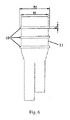
- Fig. 6 is a schematic diagram that shows the structure of the circumferential bosses of the stent graft of the invention.
- a plurality of circumferential bosses 10 integrated with the graft tube 11 are formed (three circumferential bosses are shown in the embodiments in Fig. 1 and Fig. 6 ) outside the graft tube 11, namely the material of the circumferential bosses 10 is the same as the material of the graft tube 11, both of which are flexible materials.
- Each of the plurality of circumferential bosses 10 extends around the outer circumferential surface of the graft tube 11 in the circumferential direction and protrudes towards the outer side of the graft tube 11.
- the circumferential bosses 10 and the stent sections 17 of the main section 15 are alternately arranged in the axial direction of the main section 15.
- the plurality of circumferential bosses 10 are arranged on the outer circumference of the graft tube 11 at equal intervals in the axial direction of the main section 15. But, those skilled in the art can understand that in some other embodiments of the invention, the spacing distances between the plurality of circumferential bosses 10 may be also not equal.
- the circumferential bosses 10 outside the graft of the invention have the following characteristics:
- the compressions between the stent sections 17 will be irregular, and since the support strength of the stent section is large, the impact of the apex of the stent section on the graft(s) of the graft tube 11 is comparatively strong, and a long-term wear may result in that the apex of the stent section bursts the graft, thus the stent graft may be rendered leaky; and after the addition of the circumferential bosses 10, the whole stent graft will be compressed along the trace of the circumferential bosses 10 after the stent graft is applied by an axial compression force, so the wear of the stent graft by the apex of the stent section may be relieved.
- the stent graft After the stent graft is implanted into the human body, the case that there is a plaque on the blood vessel wall at the implantation site may be encountered, and after the part having a metal stent meets the plaque, adverse consequences such as a bad adhesion and an internal leakage are likely resulted in.
- the stent graft 1 with the circumferential bosses 10 of the invention is implanted into the blood vessel tumor cavity, along with the impact of the blood flow, the contact of the graft material of a circumferential boss structure with the blood vessel wall will be increased, so the adhesion properties of the whole stent graft may be increased and the internal leakage may be reduced.
- the stent graft 1 of the invention is provided with a plurality of circumferential bosses 10, so the whole of the stent graft 1 is bent along with the shape of the circumferential bosses 10 when the stent graft 1 is bent.
- the bending properties of the whole of the stent graft may be increased after the suturing of the stent sections.
- the outer diameter W2 of the circumferential boss 10 is larger than the outer diameter W1 of the graft tube 11 of the stent graft 1 by 1 mm-3 mm (see Fig. 6 ), and the width H1 of the circumferential boss 10 is between 0.5 mm and 1.5 mm. If the width H1 of the circumferential boss 10 is too narrow, the circumferential boss 10 may be rendered unable to effectively reduce the wear between the stent section and the graft and achieve the effect of bending flexibility; and if the width H1 of the circumferential boss 10 is too wide, the interval between the stent sections may be rendered too large, which, on the contrary, is more likely to cause folding.
- the outer diameter of the circumferential boss 10 refers to the diameter of the outermost part of the circumferential boss 10 extending around the center axis of the stent graft 1
- the width of the circumferential boss 10 refers to the axial size of the circumferential boss 10 measured along the center axis of the stent graft 1.
- Fig. 7 is a schematic diagram of the stent graft with the circumferential bosses 10 before bending, wherein the graft tube of the stent graft is straight.
- Fig. 8 is a schematic diagram of the stent graft with the circumferential bosses 10 after bending, wherein the graft tube of the stent graft 1 is bent, wherein Fig. 8(a) shows the stent graft 1 in a normal bending form, and Fig. 8(b) shows the stent graft 1 in an ultimate bending form.
- circumferential bosses 10 may facilitate the positioning of the stent sections and facilitate precise suturing, so that the practicability of the suturing process is greatly increased.
- All the stent sections for treating the abdominal aortic aneurysm have comparatively large diameters, a large-scale cutting machine is comparatively expensive, and some after-treatment operations, e.g., polishing, stereotyping, sand blasting, or other subsequent processing operations, are to be performed after the cutting of the stent sections, so the price for cutting the stent sections is high.
- the woven stent sections can stereotype the desired outlines of the stent sections only by various weaving and stereotyping molds, i.e., the adoption of the woven stent sections can both reduce the cost and ensure the same performance.
- the stent graft 1 of the invention it is allowed to form only the bare section 2 into a cut stent section and form all the other stent sections, including but not limited to the aforementioned wave section 3 and stent section 17, as well as the sections in the branch sections 5 and the central structure of the transition section to be mentioned below, into woven stent sections, thereby reducing the cost.
- the stent portion 16 further includes at least two branch sections 5, and the proximal ends of the branch sections 5 are connected with the distal end of the main section 15.
- the stent portion 16 further includes a transition section 4, which is located between the main section 15 and the branch sections 5 and is used for transitioning the main section 15 to the branch sections 5.
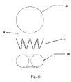
- the design of the transition section 4 in the stent portion 16 of the stent graft is as shown in Fig. 11.
- Fig. 11 is an exploded detailed view of the transition section 4.
- the stent sections Since the diameter of the main section 15 of the stent graft 1 is comparatively large, and the diameter of the branch section 5 is comparatively small, if the connection is directly made from the main section of the stent graft 1 to the branch sections, the impact of the blood flow on the graft at the connection section, especially the graft at the bifurcation and the neighboring suture lines, will be very large, which will result in that the graft in the area at the bifurcation is severely impacted by the blood flow to be damaged, and which will result in a severe wear at the suture of the main section and the first section of the stent sections of the branch sections, so the stent sections may drop or leakage of blood may occur at the bifurcation, and thereby cause a severe result.
- the invention designs a transition section 4, which can smoothly and stably transition the part having a large diameter of the stent graft at the proximal end to the parts having small diameters of the two branch sections at the distal end.
- the diameter of the proximal end portion 12 of the transition section 4 is the same as the diameter of the distal end portion of the main section 15, and the transition section 4 tapers gradually from its proximal end portion 12 to its distal end portion 14 to perform a smooth transition to the two branch sections 5, where the reference sign 13 denotes a central structure of the transition section. It should be noted that in Fig.
- the proximal end refers to the upper end of the figure
- the distal end refers to the lower end of the figure.
- a small wave section 3 having a woven structure can increase the adhesion and roundness properties of the proximal end of the stent graft.
- the main section 15 can further include a small wave section 3, which is arranged close to the bare section 2.
- the small wave section 3 is located at the edge portion the proximal end of the graft tube 11 formed of the graft material.
- the small wave section 3 is used for improving the adhesion properties of the proximal end of the stent graft and preventing the generation of the internal leakage.
- the waveform structure of the small wave section 3 is dimensionally smaller than the waveform structures of the other stent sections in the stent portion 16.
- the waveform of the small wave section 3 can be designed as an equal-height structure or a height-changing structure.
- the filament diameter of the small wave section is comparatively thin.
- the structure of the small wave section is as shown in Fig. 9 and Fig. 10.
- Fig. 9 is a schematic diagram that shows the small wave section 3 having an equal-height structure.
- the small wave section 3 has an equal-height structure, i.e., the structure in which all the upper apexes are on the same plane, all the lower apexes are on the other same plane, and the respective stent rods have the same length is called an equal-height structure.
- Fig. 10 is a schematic diagram that shows the small wave section 3 having a height-changing structure.
- the filament diameter of the small wave section 3 is selected to be comparatively thin, and a filament diameter of 0.2032-0.254 millimeter (0.008-0.010 inch), which is greatly smaller than the filament diameter of the stent sections of the main section, is generally selected.
- the stent graft of the invention is adapted to treat the abdominal aortic aneurysm.
- the stent graft is released after being guided to the lesion site, the stent made of metal material supports the graft material on the normal blood vessel walls at the both ends of the diseased blood vessel, so that the stent graft isolates the aneurysm from the blood flow within the blood vessel cavity to thereby eliminate the risk of break of the blood vessel and achieve the object of maintaining the blood flow of the aorta smooth; and the outer wall of the blood vessel is retracted due to the negative pressure, the normal blood vessel shape can be slowly restored, and the vascular intima cells permeate the micropores in the graft material and finally completely cover the stent graft to achieve endothelialization of the stent graft.
- the invention can be applied to the cases of the abdominal aortic aneurysm involving a short tumor neck and a bent tumor neck, i.e., the stent graft of the invention is more suitable for a comparatively short tumor neck length and a tumor neck that is bent more, has better adhesion and roundness properties, has a moderate support strength, can prevent a long-term displacement of the stent graft after the implantation of the stent graft and the like.
- the stent graft of the invention has the following advantageous technical effects:
- the stent graft of the invention can meet the various performance indexes to evaluate this kind of stent grafts as mentioned above in the Description, i.e., the stent graft has a very good tightness and thus can isolate the tumor cavity from the blood; the bare section carries a barb, and thus can prevent the displacement of the stent after the implantation of the stent; the adoption of a proper release resistance can smoothly release the stent and avoid the displacement of the stent; the rear release function of the stent can accurately position the stent graft; the stent graft has a comparatively low edge height and thus has a good flexibility; and the stent graft can be adapted to a smaller tumor neck length.
- the invention can be adapted to various types of abdominal aortic aneurysms.
Landscapes
- Health & Medical Sciences (AREA)
- Engineering & Computer Science (AREA)
- Biomedical Technology (AREA)
- Life Sciences & Earth Sciences (AREA)
- General Health & Medical Sciences (AREA)
- Transplantation (AREA)
- Heart & Thoracic Surgery (AREA)
- Vascular Medicine (AREA)
- Cardiology (AREA)
- Animal Behavior & Ethology (AREA)
- Oral & Maxillofacial Surgery (AREA)
- Public Health (AREA)
- Veterinary Medicine (AREA)
- Gastroenterology & Hepatology (AREA)
- Pulmonology (AREA)
- Prostheses (AREA)
- Media Introduction/Drainage Providing Device (AREA)
Applications Claiming Priority (2)
| Application Number | Priority Date | Filing Date | Title |
|---|---|---|---|
| CN201310534126.2A CN104586537B (zh) | 2013-10-31 | 2013-10-31 | 一种覆膜支架 |
| PCT/CN2014/089968 WO2015062531A1 (zh) | 2013-10-31 | 2014-10-31 | 一种覆膜支架 |
Publications (3)
| Publication Number | Publication Date |
|---|---|
| EP3064172A1 true EP3064172A1 (de) | 2016-09-07 |
| EP3064172A4 EP3064172A4 (de) | 2017-03-29 |
| EP3064172B1 EP3064172B1 (de) | 2022-10-05 |
Family
ID=53003378
Family Applications (1)
| Application Number | Title | Priority Date | Filing Date |
|---|---|---|---|
| EP14858484.0A Active EP3064172B1 (de) | 2013-10-31 | 2014-10-31 | Beschichteter stent-graft |
Country Status (8)
| Country | Link |
|---|---|
| EP (1) | EP3064172B1 (de) |
| CN (1) | CN104586537B (de) |
| AR (1) | AR100664A1 (de) |
| BR (1) | BR112016009186B1 (de) |
| ES (1) | ES2929190T3 (de) |
| PL (1) | PL3064172T3 (de) |
| PT (1) | PT3064172T (de) |
| WO (1) | WO2015062531A1 (de) |
Families Citing this family (14)
| Publication number | Priority date | Publication date | Assignee | Title |
|---|---|---|---|---|
| JP6200465B2 (ja) * | 2015-07-23 | 2017-09-20 | 日本ライフライン株式会社 | ステントグラフト |
| CN106806043B (zh) * | 2015-11-30 | 2019-04-26 | 先健科技(深圳)有限公司 | 管腔支架及管腔支架系统 |
| CN105853023B (zh) * | 2016-04-18 | 2019-07-05 | 谷涌泉 | 一种开窗覆膜支架 |
| CN107569311A (zh) * | 2017-07-05 | 2018-01-12 | 杭州唯强医疗科技有限公司 | 环形支撑架 |
| CN107397610A (zh) * | 2017-08-25 | 2017-11-28 | 杭州唯强医疗科技有限公司 | 覆膜支架 |
| CN109567981B (zh) * | 2017-09-29 | 2024-09-20 | 上海微创心脉医疗科技股份有限公司 | 支架系统及其输送装置、后释放结构与支架 |
| CN112760776B (zh) * | 2019-11-01 | 2025-09-12 | 浙江脉通智造科技(集团)有限公司 | 覆膜结构、覆膜管、覆膜管制备方法及覆膜支架 |
| WO2021129286A1 (zh) * | 2019-12-23 | 2021-07-01 | 杭州唯强医疗科技有限公司 | 覆膜支架系统及其覆膜支架 |
| CN113081388B (zh) * | 2019-12-23 | 2025-11-07 | 杭州唯强医疗科技有限公司 | 覆膜支架系统及其覆膜支架 |
| CN114569299B (zh) * | 2020-12-02 | 2025-09-16 | 先健科技(深圳)有限公司 | 覆膜支架 |
| CN114681115B (zh) * | 2020-12-30 | 2025-03-28 | 浙江脉通智造科技(集团)有限公司 | 覆膜管定型装置及定型方法、覆膜支架的制备方法 |
| CN113876467B (zh) * | 2021-12-08 | 2022-04-15 | 上海微创心脉医疗科技(集团)股份有限公司 | 覆膜支架 |
| CN115429372B (zh) * | 2022-10-27 | 2023-02-03 | 北京华脉泰科医疗器械股份有限公司 | 瘤腔内密封支架 |
| CN116687619A (zh) * | 2023-07-31 | 2023-09-05 | 浙江归创医疗科技有限公司 | 一种腹主动脉覆膜支架 |
Family Cites Families (16)
| Publication number | Priority date | Publication date | Assignee | Title |
|---|---|---|---|---|
| GB9518400D0 (en) * | 1995-09-08 | 1995-11-08 | Anson Medical Ltd | A surgical graft/stent system |
| US6395019B2 (en) * | 1998-02-09 | 2002-05-28 | Trivascular, Inc. | Endovascular graft |
| DK174814B1 (da) * | 1998-02-25 | 2003-12-01 | Cook William Europ | Stentaggregat |
| US6280466B1 (en) * | 1999-12-03 | 2001-08-28 | Teramed Inc. | Endovascular graft system |
| AU2002248765B2 (en) * | 2001-03-28 | 2006-11-30 | Cook Medical Technologies Llc | Modular stent graft assembly and use thereof |
| US20060224232A1 (en) * | 2005-04-01 | 2006-10-05 | Trivascular, Inc. | Hybrid modular endovascular graft |
| CN2817768Y (zh) * | 2005-05-24 | 2006-09-20 | 微创医疗器械(上海)有限公司 | 一种覆膜支架的主体支架段及覆膜支架 |
| US20070239267A1 (en) * | 2006-03-28 | 2007-10-11 | Medtronic Vascular, Inc. | Stent Graft With Healing Promoting Necks |
| US7481836B2 (en) * | 2006-03-30 | 2009-01-27 | Medtronic Vascular, Inc. | Prosthesis with coupling zone and methods |
| US7655034B2 (en) | 2006-11-14 | 2010-02-02 | Medtronic Vascular, Inc. | Stent-graft with anchoring pins |
| CN102076281B (zh) * | 2008-06-30 | 2014-11-05 | 波顿医疗公司 | 用于腹主动脉瘤的系统和方法 |
| US20110071614A1 (en) | 2009-09-24 | 2011-03-24 | David Christopher Majercak | Stent - graft suture locks |
| CN102048596A (zh) * | 2009-11-09 | 2011-05-11 | 于存涛 | 人工四分支血管支架象鼻及其固定装置 |
| US20110218609A1 (en) * | 2010-02-10 | 2011-09-08 | Trivascular, Inc. | Fill tube manifold and delivery methods for endovascular graft |
| CN202342239U (zh) * | 2011-09-01 | 2012-07-25 | 北京华脉泰科医疗器械有限公司 | 一种主动脉覆膜支架 |
| CN102488575A (zh) * | 2011-11-11 | 2012-06-13 | 许尚栋 | 主动脉开窗支架 |
-
2013
- 2013-10-31 CN CN201310534126.2A patent/CN104586537B/zh active Active
-
2014
- 2014-10-31 ES ES14858484T patent/ES2929190T3/es active Active
- 2014-10-31 WO PCT/CN2014/089968 patent/WO2015062531A1/zh not_active Ceased
- 2014-10-31 EP EP14858484.0A patent/EP3064172B1/de active Active
- 2014-10-31 PL PL14858484.0T patent/PL3064172T3/pl unknown
- 2014-10-31 BR BR112016009186-8A patent/BR112016009186B1/pt active IP Right Grant
- 2014-10-31 PT PT148584840T patent/PT3064172T/pt unknown
- 2014-11-03 AR ARP140104098A patent/AR100664A1/es active IP Right Grant
Also Published As
| Publication number | Publication date |
|---|---|
| PT3064172T (pt) | 2022-11-03 |
| WO2015062531A1 (zh) | 2015-05-07 |
| BR112016009186A2 (de) | 2017-08-01 |
| AR100664A1 (es) | 2016-10-26 |
| CN104586537A (zh) | 2015-05-06 |
| EP3064172B1 (de) | 2022-10-05 |
| PL3064172T3 (pl) | 2023-02-06 |
| BR112016009186B1 (pt) | 2022-10-11 |
| ES2929190T3 (es) | 2022-11-25 |
| EP3064172A4 (de) | 2017-03-29 |
| CN104586537B (zh) | 2017-05-10 |
Similar Documents
| Publication | Publication Date | Title |
|---|---|---|
| EP3064172B1 (de) | Beschichteter stent-graft | |
| EP3064171B1 (de) | Beschichteter stent-graft | |
| US20230104099A1 (en) | Braided stent with expansion ring and method of delivery | |
| CN101856277B (zh) | 一种可回收的单向活瓣覆膜支架 | |
| CN114569303B (zh) | 覆膜支架 | |
| KR102197010B1 (ko) | 스텐트 | |
| CN103153214A (zh) | 用于恢复血流并且将构件植入人体内的设备 | |
| CN116370167B (zh) | 一种覆膜支架 | |
| WO2023071792A1 (zh) | 覆膜支架和组合支架 | |
| CN102379761A (zh) | 一种支架输送装置 | |
| CN114652486A (zh) | 覆膜支架 | |
| US20170100268A1 (en) | Flexible stent | |
| CN114099062A (zh) | 覆膜支架 | |
| CN215458979U (zh) | 一种血管支架 | |
| CN215458977U (zh) | 一种血管支架 | |
| CN201098156Y (zh) | 血管开口支架 | |
| TW202131878A (zh) | 支架及其檢查方法 | |
| CN114469444A (zh) | 瓣膜支架和瓣膜假体 | |
| CN219645967U (zh) | 血管外支撑装置 | |
| CN118436464A (zh) | 一种主动脉裸支架结构 | |
| CN204671319U (zh) | 一种适用于主动脉夹层的带远端裸支架的锥形支架移植物 | |
| CN205307149U (zh) | 心脏冠状动脉支架 | |
| CN105213077B (zh) | 一种覆网支架 | |
| CN117224296B (zh) | 一种开窗支架 | |
| CN220608845U (zh) | 一种医用导向定位装置 |
Legal Events
| Date | Code | Title | Description |
|---|---|---|---|
| PUAI | Public reference made under article 153(3) epc to a published international application that has entered the european phase |
Free format text: ORIGINAL CODE: 0009012 |
|
| 17P | Request for examination filed |
Effective date: 20160510 |
|
| AK | Designated contracting states |
Kind code of ref document: A1 Designated state(s): AL AT BE BG CH CY CZ DE DK EE ES FI FR GB GR HR HU IE IS IT LI LT LU LV MC MK MT NL NO PL PT RO RS SE SI SK SM TR |
|
| AX | Request for extension of the european patent |
Extension state: BA ME |
|
| DAX | Request for extension of the european patent (deleted) | ||
| A4 | Supplementary search report drawn up and despatched |
Effective date: 20170224 |
|
| RIC1 | Information provided on ipc code assigned before grant |
Ipc: A61F 2/848 20130101ALI20170220BHEP Ipc: A61F 2/07 20130101AFI20170220BHEP |
|
| RAP1 | Party data changed (applicant data changed or rights of an application transferred) |
Owner name: SHANGHAI MICROPORT ENDOVASCULAR MEDTECH CO., LTD. |
|
| STAA | Information on the status of an ep patent application or granted ep patent |
Free format text: STATUS: EXAMINATION IS IN PROGRESS |
|
| 17Q | First examination report despatched |
Effective date: 20200408 |
|
| GRAP | Despatch of communication of intention to grant a patent |
Free format text: ORIGINAL CODE: EPIDOSNIGR1 |
|
| STAA | Information on the status of an ep patent application or granted ep patent |
Free format text: STATUS: GRANT OF PATENT IS INTENDED |
|
| INTG | Intention to grant announced |
Effective date: 20220609 |
|
| GRAS | Grant fee paid |
Free format text: ORIGINAL CODE: EPIDOSNIGR3 |
|
| GRAA | (expected) grant |
Free format text: ORIGINAL CODE: 0009210 |
|
| STAA | Information on the status of an ep patent application or granted ep patent |
Free format text: STATUS: THE PATENT HAS BEEN GRANTED |
|
| RAP3 | Party data changed (applicant data changed or rights of an application transferred) |
Owner name: SHANGHAI MICROPORT ENDOVASCULAR MEDTECH (GROUP) CO., LTD. |
|
| AK | Designated contracting states |
Kind code of ref document: B1 Designated state(s): AL AT BE BG CH CY CZ DE DK EE ES FI FR GB GR HR HU IE IS IT LI LT LU LV MC MK MT NL NO PL PT RO RS SE SI SK SM TR |
|
| REG | Reference to a national code |
Ref country code: GB Ref legal event code: FG4D |
|
| REG | Reference to a national code |
Ref country code: CH Ref legal event code: EP |
|
| REG | Reference to a national code |
Ref country code: AT Ref legal event code: REF Ref document number: 1522281 Country of ref document: AT Kind code of ref document: T Effective date: 20221015 |
|
| REG | Reference to a national code |
Ref country code: IE Ref legal event code: FG4D |
|
| REG | Reference to a national code |
Ref country code: DE Ref legal event code: R096 Ref document number: 602014085165 Country of ref document: DE |
|
| REG | Reference to a national code |
Ref country code: PT Ref legal event code: SC4A Ref document number: 3064172 Country of ref document: PT Date of ref document: 20221103 Kind code of ref document: T Free format text: AVAILABILITY OF NATIONAL TRANSLATION Effective date: 20221026 |
|
| REG | Reference to a national code |
Ref country code: ES Ref legal event code: FG2A Ref document number: 2929190 Country of ref document: ES Kind code of ref document: T3 Effective date: 20221125 |
|
| REG | Reference to a national code |
Ref country code: GR Ref legal event code: EP Ref document number: 20220402175 Country of ref document: GR Effective date: 20221212 |
|
| REG | Reference to a national code |
Ref country code: LT Ref legal event code: MG9D |
|
| REG | Reference to a national code |
Ref country code: NL Ref legal event code: MP Effective date: 20221005 |
|
| REG | Reference to a national code |
Ref country code: AT Ref legal event code: MK05 Ref document number: 1522281 Country of ref document: AT Kind code of ref document: T Effective date: 20221005 |
|
| PG25 | Lapsed in a contracting state [announced via postgrant information from national office to epo] |
Ref country code: NL Free format text: LAPSE BECAUSE OF FAILURE TO SUBMIT A TRANSLATION OF THE DESCRIPTION OR TO PAY THE FEE WITHIN THE PRESCRIBED TIME-LIMIT Effective date: 20221005 |
|
| PG25 | Lapsed in a contracting state [announced via postgrant information from national office to epo] |
Ref country code: SE Free format text: LAPSE BECAUSE OF FAILURE TO SUBMIT A TRANSLATION OF THE DESCRIPTION OR TO PAY THE FEE WITHIN THE PRESCRIBED TIME-LIMIT Effective date: 20221005 Ref country code: NO Free format text: LAPSE BECAUSE OF FAILURE TO SUBMIT A TRANSLATION OF THE DESCRIPTION OR TO PAY THE FEE WITHIN THE PRESCRIBED TIME-LIMIT Effective date: 20230105 Ref country code: LT Free format text: LAPSE BECAUSE OF FAILURE TO SUBMIT A TRANSLATION OF THE DESCRIPTION OR TO PAY THE FEE WITHIN THE PRESCRIBED TIME-LIMIT Effective date: 20221005 Ref country code: FI Free format text: LAPSE BECAUSE OF FAILURE TO SUBMIT A TRANSLATION OF THE DESCRIPTION OR TO PAY THE FEE WITHIN THE PRESCRIBED TIME-LIMIT Effective date: 20221005 Ref country code: AT Free format text: LAPSE BECAUSE OF FAILURE TO SUBMIT A TRANSLATION OF THE DESCRIPTION OR TO PAY THE FEE WITHIN THE PRESCRIBED TIME-LIMIT Effective date: 20221005 |
|
| PG25 | Lapsed in a contracting state [announced via postgrant information from national office to epo] |
Ref country code: RS Free format text: LAPSE BECAUSE OF FAILURE TO SUBMIT A TRANSLATION OF THE DESCRIPTION OR TO PAY THE FEE WITHIN THE PRESCRIBED TIME-LIMIT Effective date: 20221005 Ref country code: LV Free format text: LAPSE BECAUSE OF FAILURE TO SUBMIT A TRANSLATION OF THE DESCRIPTION OR TO PAY THE FEE WITHIN THE PRESCRIBED TIME-LIMIT Effective date: 20221005 Ref country code: IS Free format text: LAPSE BECAUSE OF FAILURE TO SUBMIT A TRANSLATION OF THE DESCRIPTION OR TO PAY THE FEE WITHIN THE PRESCRIBED TIME-LIMIT Effective date: 20230205 Ref country code: HR Free format text: LAPSE BECAUSE OF FAILURE TO SUBMIT A TRANSLATION OF THE DESCRIPTION OR TO PAY THE FEE WITHIN THE PRESCRIBED TIME-LIMIT Effective date: 20221005 |
|
| REG | Reference to a national code |
Ref country code: BE Ref legal event code: MM Effective date: 20221031 |
|
| PG25 | Lapsed in a contracting state [announced via postgrant information from national office to epo] |
Ref country code: LU Free format text: LAPSE BECAUSE OF NON-PAYMENT OF DUE FEES Effective date: 20221031 |
|
| REG | Reference to a national code |
Ref country code: DE Ref legal event code: R097 Ref document number: 602014085165 Country of ref document: DE |
|
| PG25 | Lapsed in a contracting state [announced via postgrant information from national office to epo] |
Ref country code: SM Free format text: LAPSE BECAUSE OF FAILURE TO SUBMIT A TRANSLATION OF THE DESCRIPTION OR TO PAY THE FEE WITHIN THE PRESCRIBED TIME-LIMIT Effective date: 20221005 Ref country code: RO Free format text: LAPSE BECAUSE OF FAILURE TO SUBMIT A TRANSLATION OF THE DESCRIPTION OR TO PAY THE FEE WITHIN THE PRESCRIBED TIME-LIMIT Effective date: 20221005 Ref country code: MC Free format text: LAPSE BECAUSE OF FAILURE TO SUBMIT A TRANSLATION OF THE DESCRIPTION OR TO PAY THE FEE WITHIN THE PRESCRIBED TIME-LIMIT Effective date: 20221005 Ref country code: EE Free format text: LAPSE BECAUSE OF FAILURE TO SUBMIT A TRANSLATION OF THE DESCRIPTION OR TO PAY THE FEE WITHIN THE PRESCRIBED TIME-LIMIT Effective date: 20221005 Ref country code: DK Free format text: LAPSE BECAUSE OF FAILURE TO SUBMIT A TRANSLATION OF THE DESCRIPTION OR TO PAY THE FEE WITHIN THE PRESCRIBED TIME-LIMIT Effective date: 20221005 Ref country code: CZ Free format text: LAPSE BECAUSE OF FAILURE TO SUBMIT A TRANSLATION OF THE DESCRIPTION OR TO PAY THE FEE WITHIN THE PRESCRIBED TIME-LIMIT Effective date: 20221005 |
|
| PLBE | No opposition filed within time limit |
Free format text: ORIGINAL CODE: 0009261 |
|
| STAA | Information on the status of an ep patent application or granted ep patent |
Free format text: STATUS: NO OPPOSITION FILED WITHIN TIME LIMIT |
|
| PG25 | Lapsed in a contracting state [announced via postgrant information from national office to epo] |
Ref country code: SK Free format text: LAPSE BECAUSE OF FAILURE TO SUBMIT A TRANSLATION OF THE DESCRIPTION OR TO PAY THE FEE WITHIN THE PRESCRIBED TIME-LIMIT Effective date: 20221005 Ref country code: AL Free format text: LAPSE BECAUSE OF FAILURE TO SUBMIT A TRANSLATION OF THE DESCRIPTION OR TO PAY THE FEE WITHIN THE PRESCRIBED TIME-LIMIT Effective date: 20221005 |
|
| 26N | No opposition filed |
Effective date: 20230706 |
|
| PG25 | Lapsed in a contracting state [announced via postgrant information from national office to epo] |
Ref country code: BE Free format text: LAPSE BECAUSE OF NON-PAYMENT OF DUE FEES Effective date: 20221031 |
|
| PG25 | Lapsed in a contracting state [announced via postgrant information from national office to epo] |
Ref country code: IE Free format text: LAPSE BECAUSE OF NON-PAYMENT OF DUE FEES Effective date: 20221031 |
|
| PG25 | Lapsed in a contracting state [announced via postgrant information from national office to epo] |
Ref country code: SI Free format text: LAPSE BECAUSE OF FAILURE TO SUBMIT A TRANSLATION OF THE DESCRIPTION OR TO PAY THE FEE WITHIN THE PRESCRIBED TIME-LIMIT Effective date: 20221005 |
|
| P01 | Opt-out of the competence of the unified patent court (upc) registered |
Effective date: 20231128 |
|
| PG25 | Lapsed in a contracting state [announced via postgrant information from national office to epo] |
Ref country code: HU Free format text: LAPSE BECAUSE OF FAILURE TO SUBMIT A TRANSLATION OF THE DESCRIPTION OR TO PAY THE FEE WITHIN THE PRESCRIBED TIME-LIMIT; INVALID AB INITIO Effective date: 20141031 |
|
| PG25 | Lapsed in a contracting state [announced via postgrant information from national office to epo] |
Ref country code: CY Free format text: LAPSE BECAUSE OF FAILURE TO SUBMIT A TRANSLATION OF THE DESCRIPTION OR TO PAY THE FEE WITHIN THE PRESCRIBED TIME-LIMIT Effective date: 20221005 |
|
| PG25 | Lapsed in a contracting state [announced via postgrant information from national office to epo] |
Ref country code: MK Free format text: LAPSE BECAUSE OF FAILURE TO SUBMIT A TRANSLATION OF THE DESCRIPTION OR TO PAY THE FEE WITHIN THE PRESCRIBED TIME-LIMIT Effective date: 20221005 |
|
| PG25 | Lapsed in a contracting state [announced via postgrant information from national office to epo] |
Ref country code: TR Free format text: LAPSE BECAUSE OF FAILURE TO SUBMIT A TRANSLATION OF THE DESCRIPTION OR TO PAY THE FEE WITHIN THE PRESCRIBED TIME-LIMIT Effective date: 20221005 |
|
| PG25 | Lapsed in a contracting state [announced via postgrant information from national office to epo] |
Ref country code: BG Free format text: LAPSE BECAUSE OF FAILURE TO SUBMIT A TRANSLATION OF THE DESCRIPTION OR TO PAY THE FEE WITHIN THE PRESCRIBED TIME-LIMIT Effective date: 20221005 |
|
| PG25 | Lapsed in a contracting state [announced via postgrant information from national office to epo] |
Ref country code: MT Free format text: LAPSE BECAUSE OF FAILURE TO SUBMIT A TRANSLATION OF THE DESCRIPTION OR TO PAY THE FEE WITHIN THE PRESCRIBED TIME-LIMIT Effective date: 20221005 |
|
| REG | Reference to a national code |
Ref country code: CH Ref legal event code: U11 Free format text: ST27 STATUS EVENT CODE: U-0-0-U10-U11 (AS PROVIDED BY THE NATIONAL OFFICE) Effective date: 20251101 |
|
| PGFP | Annual fee paid to national office [announced via postgrant information from national office to epo] |
Ref country code: PT Payment date: 20251024 Year of fee payment: 12 |
|
| PGFP | Annual fee paid to national office [announced via postgrant information from national office to epo] |
Ref country code: DE Payment date: 20251021 Year of fee payment: 12 |
|
| PGFP | Annual fee paid to national office [announced via postgrant information from national office to epo] |
Ref country code: GB Payment date: 20251022 Year of fee payment: 12 |
|
| PGFP | Annual fee paid to national office [announced via postgrant information from national office to epo] |
Ref country code: IT Payment date: 20251024 Year of fee payment: 12 |
|
| PGFP | Annual fee paid to national office [announced via postgrant information from national office to epo] |
Ref country code: FR Payment date: 20251030 Year of fee payment: 12 |
|
| PGFP | Annual fee paid to national office [announced via postgrant information from national office to epo] |
Ref country code: GR Payment date: 20251022 Year of fee payment: 12 |
|
| PGFP | Annual fee paid to national office [announced via postgrant information from national office to epo] |
Ref country code: CH Payment date: 20251101 Year of fee payment: 12 |
|
| PGFP | Annual fee paid to national office [announced via postgrant information from national office to epo] |
Ref country code: PL Payment date: 20251024 Year of fee payment: 12 |
|
| PGFP | Annual fee paid to national office [announced via postgrant information from national office to epo] |
Ref country code: ES Payment date: 20251210 Year of fee payment: 12 |