EP3064263A1 - Éliminateur de brouillard léger pour systèmes d'injection de réservoir de carburant d'aéronef - Google Patents
Éliminateur de brouillard léger pour systèmes d'injection de réservoir de carburant d'aéronef Download PDFInfo
- Publication number
- EP3064263A1 EP3064263A1 EP16158196.2A EP16158196A EP3064263A1 EP 3064263 A1 EP3064263 A1 EP 3064263A1 EP 16158196 A EP16158196 A EP 16158196A EP 3064263 A1 EP3064263 A1 EP 3064263A1
- Authority
- EP
- European Patent Office
- Prior art keywords
- droplets
- layered assembly
- bleed air
- engine bleed
- container
- Prior art date
- Legal status (The legal status is an assumption and is not a legal conclusion. Google has not performed a legal analysis and makes no representation as to the accuracy of the status listed.)
- Granted
Links
- 239000003595 mist Substances 0.000 title claims abstract description 49
- 239000002828 fuel tank Substances 0.000 title 1
- 239000011159 matrix material Substances 0.000 claims abstract description 38
- 239000012530 fluid Substances 0.000 claims abstract description 37
- 230000008030 elimination Effects 0.000 claims abstract description 26
- 238000003379 elimination reaction Methods 0.000 claims abstract description 26
- 238000004891 communication Methods 0.000 claims abstract description 18
- 230000005484 gravity Effects 0.000 claims abstract description 10
- 238000000034 method Methods 0.000 claims description 19
- CBENFWSGALASAD-UHFFFAOYSA-N Ozone Chemical compound [O-][O+]=O CBENFWSGALASAD-UHFFFAOYSA-N 0.000 claims description 10
- 239000000463 material Substances 0.000 claims description 10
- 239000004033 plastic Substances 0.000 claims description 8
- QVGXLLKOCUKJST-UHFFFAOYSA-N atomic oxygen Chemical compound [O] QVGXLLKOCUKJST-UHFFFAOYSA-N 0.000 claims description 6
- 239000001301 oxygen Substances 0.000 claims description 6
- 229910052760 oxygen Inorganic materials 0.000 claims description 6
- 239000003054 catalyst Substances 0.000 claims description 4
- 239000000356 contaminant Substances 0.000 claims description 3
- 239000007788 liquid Substances 0.000 claims description 3
- 230000003116 impacting effect Effects 0.000 claims description 2
- 239000000443 aerosol Substances 0.000 description 9
- 239000012528 membrane Substances 0.000 description 9
- 239000003921 oil Substances 0.000 description 4
- 238000000926 separation method Methods 0.000 description 3
- IJGRMHOSHXDMSA-UHFFFAOYSA-N Atomic nitrogen Chemical compound N#N IJGRMHOSHXDMSA-UHFFFAOYSA-N 0.000 description 2
- 239000004593 Epoxy Substances 0.000 description 2
- 230000008901 benefit Effects 0.000 description 2
- 239000010725 compressor oil Substances 0.000 description 2
- 238000011109 contamination Methods 0.000 description 2
- 230000009849 deactivation Effects 0.000 description 2
- 239000000835 fiber Substances 0.000 description 2
- 239000007789 gas Substances 0.000 description 2
- 229920000728 polyester Polymers 0.000 description 2
- 230000002028 premature Effects 0.000 description 2
- 230000003247 decreasing effect Effects 0.000 description 1
- 230000003993 interaction Effects 0.000 description 1
- 238000012986 modification Methods 0.000 description 1
- 230000004048 modification Effects 0.000 description 1
- 229910052757 nitrogen Inorganic materials 0.000 description 1
- 230000035699 permeability Effects 0.000 description 1
- 239000002985 plastic film Substances 0.000 description 1
- 230000002265 prevention Effects 0.000 description 1
- 239000000126 substance Substances 0.000 description 1
Images


Classifications
-
- F—MECHANICAL ENGINEERING; LIGHTING; HEATING; WEAPONS; BLASTING
- F02—COMBUSTION ENGINES; HOT-GAS OR COMBUSTION-PRODUCT ENGINE PLANTS
- F02C—GAS-TURBINE PLANTS; AIR INTAKES FOR JET-PROPULSION PLANTS; CONTROLLING FUEL SUPPLY IN AIR-BREATHING JET-PROPULSION PLANTS
- F02C9/00—Controlling gas-turbine plants; Controlling fuel supply in air- breathing jet-propulsion plants
- F02C9/16—Control of working fluid flow
- F02C9/18—Control of working fluid flow by bleeding, bypassing or acting on variable working fluid interconnections between turbines or compressors or their stages
-
- B—PERFORMING OPERATIONS; TRANSPORTING
- B01—PHYSICAL OR CHEMICAL PROCESSES OR APPARATUS IN GENERAL
- B01D—SEPARATION
- B01D39/00—Filtering material for liquid or gaseous fluids
- B01D39/14—Other self-supporting filtering material ; Other filtering material
- B01D39/16—Other self-supporting filtering material ; Other filtering material of organic material, e.g. synthetic fibres
-
- B—PERFORMING OPERATIONS; TRANSPORTING
- B01—PHYSICAL OR CHEMICAL PROCESSES OR APPARATUS IN GENERAL
- B01D—SEPARATION
- B01D45/00—Separating dispersed particles from gases or vapours by gravity, inertia, or centrifugal forces
- B01D45/12—Separating dispersed particles from gases or vapours by gravity, inertia, or centrifugal forces by centrifugal forces
- B01D45/16—Separating dispersed particles from gases or vapours by gravity, inertia, or centrifugal forces by centrifugal forces generated by the winding course of the gas stream, the centrifugal forces being generated solely or partly by mechanical means, e.g. fixed swirl vanes
-
- B—PERFORMING OPERATIONS; TRANSPORTING
- B01—PHYSICAL OR CHEMICAL PROCESSES OR APPARATUS IN GENERAL
- B01D—SEPARATION
- B01D2239/00—Aspects relating to filtering material for liquid or gaseous fluids
- B01D2239/06—Filter cloth, e.g. knitted, woven non-woven; self-supported material
- B01D2239/065—More than one layer present in the filtering material
-
- B—PERFORMING OPERATIONS; TRANSPORTING
- B01—PHYSICAL OR CHEMICAL PROCESSES OR APPARATUS IN GENERAL
- B01D—SEPARATION
- B01D2239/00—Aspects relating to filtering material for liquid or gaseous fluids
- B01D2239/06—Filter cloth, e.g. knitted, woven non-woven; self-supported material
- B01D2239/069—Special geometry of layers
- B01D2239/0695—Wound layers
-
- B—PERFORMING OPERATIONS; TRANSPORTING
- B01—PHYSICAL OR CHEMICAL PROCESSES OR APPARATUS IN GENERAL
- B01D—SEPARATION
- B01D2275/00—Filter media structures for filters specially adapted for separating dispersed particles from gases or vapours
- B01D2275/10—Multiple layers
- B01D2275/105—Wound layers
Definitions
- the present invention relates to membrane-based separation systems, and in particular, to a light-weight mist eliminator for a membrane-based separation system.
- mist eliminator systems function in a way to remove low pressure vapor fluids from inlet air.
- low vapor pressure fluids such as compressor oils and hydraulic fluids, typically in the form of fine aerosols (mist)
- Bleed air from aircraft turbines can contain such aerosols.
- concentration of these aerosols in bleed air can reach more than an order of magnitude larger than a maximum recommended by membrane manufacturers. Pretreatment is therefore crucial to preventing failure events such as premature membrane deactivation in aircraft nitrogen generation systems (NGS).
- NGS nitrogen generation systems
- a spiral mist elimination system includes a container with an inlet to receive engine bleed air into the container.
- the container includes a layered assembly in fluid communication with the inlet.
- the layered assembly contains a spiral shape and is concentric with a central axis of the container.
- the layered assembly imparts centrifugal motion in the engine bleed air as the engine bleed air travels spirally inward.
- a first portion of the layered assembly forces a first set of droplets in the bleed air toward an outer layer of the layered assembly.
- the first portion of the layered assembly receives the first set of droplets.
- the layered assembly also includes a mesh matrix that collects a second set of droplets out of the engine bleed air.
- the second set of droplets impacts the mesh matrix and coalesces to form a third set of droplets.
- a perforated tube is disposed along the central axis of the container. The perforated tube is in fluid communication with the layered assembly and collects the engine bleed air from the layered assembly. Gravity draws the first and third sets of droplets into a reservoir.
- Another embodiment of the present disclosure includes a method of removing mist from an air flow.
- the method includes inserting engine bleed air into a container through an inlet.
- the engine bleed air is flowed into a first end of the layered assembly.
- the layered assembly is in fluid communication with the inlet.
- the layered assembly also includes a spiral shape and is concentric with a central axis of the container. Centrifugal motion is imparted in the engine bleed air as the engine bleed air travels along a spiral flow-path through the layered assembly.
- a first set of fluid droplets is forced toward an outer layer of the layered assembly and is received by a first portion of the layered assembly.
- a second set of droplets impacts with a mesh matrix that is disposed within the layered assembly.
- the second set of droplets coalesces into a third set of droplets.
- the engine bleed air is drawn from the layered assembly into a perforated tube located along the central axis of the container.
- the perforated tube is in fluid communication with the layered assembly.
- Gravity draws the first and third sets of droplets into a reservoir where they are collected.
- FIG. 1 is a cross-sectional view of prior art centrifugal separator 10.
- Prior art centrifugal separator 10 includes housing 12, inlet 14, outlet 16, vortex generator 18, drain 20, and tube 22.
- Inlet airflow 24 enters prior art centrifugal separator 10 at inlet 14.
- Vortex generator 18 is mounted to tube 22 and includes vanes for imparting centrifugal motion in spiral airflow 26.
- Spiral airflow 26 travels in a spiral motion within prior art centrifugal separator 10.
- Inner surface 28 of prior art centrifugal separator 10 collects droplets 30 from spiral airflow 26. Droplets 30 are drawn downward by gravity along inner surface 28 and into reservoir 32. After droplets 30 are removed from spiral airflow 26, spiral airflow 26 is drawn up tube 22 and outlet airflow 34 exits prior art centrifugal separator 10 through outlet 16.
- inlet airflow 24 may contain low vapor pressure fluids such as compressor oils and hydraulic fluids, typically in the form of fine aerosols or mist.
- Spiral airflow 26 centrifugally forces the fine aerosols and mist outwardly towards inner surface 28.
- Inner surface 28 collects droplets from the fine aerosols and mist to create droplets 30. Droplets 30 are then drawn downward by gravity into reservoir 32 to be removed from prior art centrifugal separator 10 through drain 20.
- droplets 30 include mostly droplets that are larger in size. Smaller sized droplets entrained in spiral airflow 26 are not removed because the amount of centrifugal force applied to spiral airflow 26 is not enough to remove the smaller droplets of the fine aerosols or mist.
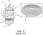
- FIG. 2 is cross-sectional view of prior art demister 36.
- Prior art demister 36 includes housing 38, airflow inlet 40, inlet diffuser 42, inner chamber 44, coalescing filter 46, reservoir 48, airflow outlet 50, and drain 52.
- Airflow 54 enters housing 38 through airflow inlet 40.
- Airflow 56 then passes through inlet diffuser 42 and into inner chamber 44.
- Airflow 56 is then drawn upwards and into coalescing filter 46.
- Airflow 58 then exits inner chamber 44 through airflow outlet 50.
- Reservoir 48 is located at the gravitational bottom of prior art demister 36 in order to collect fluids filtered by coalescing filter 46.
- coalescing filter 46 As airflow 56 is drawn through coalescing filter 46, droplets entrained in airflow 56 collide with the surfaces of coalescing filter 46. After the droplets have impacted coalescing filter 46, the droplets coalesce into larger droplets that fall from coalescing filter 46 down into reservoir 48.
- Prior art demister 36 is designed and used primarily in the chemical industry for aerosol and mist removal from air.
- Prior art demister 36 often includes a design prohibitively bulky and heavy for use in aerospace applications because the design is limited by necessity to a certain range of droplet sizes and/or airflow rate.
- the design of prior art demister 36 includes equipment weight and footprint too large for use in an aircraft system. For example, in such a design, aerosol removal performance depends on equipment size (height), which can become significant if relatively high air purity is required. Taller equipment increases the size and weight of the demister which are unsuitable attributes for aerospace applications, where decreased weight and space provide increased functionality.
- prior art demisters In order to remove the smaller droplets from engine bleed air, prior art demisters in general require a filter with very tiny holes to collect the smaller droplets. These very tiny holes impart a large pressure drop across the coalescing filter and increase the frequency for coalescing filter upset, contamination, and failure conditions requiring replacement of the coalescing filter. A large pressure drop and a high frequency of coalescing filter replacement add time and energy to the use of the prior art demisters and coalescing filters.
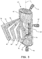
- FIG. 3 is a perspective view of spiral mist elimination system 60.
- Spiral mist elimination system 60 includes container 62, air inlet 64, layered assembly 66, perforated tube 68, reservoir 70, and air outlet 72.
- Container 62 houses layered assembly 66, perforated tube 68, and reservoir 70.
- Air inlet 64 is in fluid communication with layered assembly 66.
- Perforated tube 68 is positioned near the center of container 62 and runs generally co-axial with central axis C L .
- Perforated tube 68 is in fluid communication with layered assembly 66.
- Air outlet 72 is in fluid communication with perforated tube 68.
- Air inlet 64 receives engine bleed air 74 and communicates engine bleed air 74 into layered assembly 66.
- Layered assembly 66 is in fluid communication with air inlet 64 and contains a spiral shape concentric with central axis C L of container 62.
- the spiral shape of layered assembly 66 imparts centrifugal motion in engine bleed air 74 as engine bleed air 74 travels spirally inward along layered assembly 66.
- the outer layer of layered assembly 66 receives a first set of droplets onto the inner surface of the outer layer of layered assembly 66.
- the droplets entrained in engine bleed air 74 may contain oil or hydraulic fluid droplets, droplets of other types of liquids, and/or other types of particulate contaminants to be removed from engine bleed air 74.
- Layered assembly 66 includes mesh matrix 76.
- Mesh matrix 76 includes impermeable layer 78 and mesh layer 80.
- the outer layer of layered assembly 66 includes impermeable layer 78.
- Impermeable layer 78 receives droplets that are centrifugally forced outwards as engine bleed air 74 travels spirally inward along layered assembly 66.
- Impermeable layer 78 can include an impermeable plastic sheet or other lightweight impermeable materials. In this example, impermeable layer 78 prevents all gas and fluids from flowing across impermeable layer 78.
- Other examples may include permeable layers with varying degrees of permeability therefore allowing adjustment of the types of fluids and gas allowed to flow across the permeable layer.
- Mesh layer 80 is shaped such that a second set of droplets from engine bleed air 74 impact mesh layer 80. After the second set of droplets impacts mesh layer 80, the second set of droplets coalesces into a third set of droplets which are larger in size than the second set of droplets.
- Mesh layer 80 can include an interwoven plastic mesh with a shape that maximizes the contact area of the surfaces of mesh layer 80.
- mesh layer 80 includes a plastic netting material that is used as a support for flat sheet membranes and consists of epoxy-coated polyester fibers. The weave pattern of mesh layer 80 creates multiple head-on droplet collisions with mesh layer 80 as engine bleed air flows along its cross-section.
- mesh layer 80 may include other various shapes, thicknesses, widths, heights, materials, cross-sections, and various other factors to adjust the impaction rate of the droplets in engine bleed air 74 with mesh layer 80.
- mesh layer 80 can include an ozone catalyst for converting ozone in engine bleed air 74 into oxygen.
- engine bleed air 74 is drawn through layered assembly 66, engine bleed air 74 is drawn into perforated tube 68. Engine bleed air 74 is then drawn out of container 62 through air outlet 72.
- Reservoir 70 is located at a gravitational bottom of container 62. Reservoir 70 collects the first set of droplets received onto the inner surface of the outer layer of layered assembly 66. Reservoir 70 also collects the third set of droplets from mesh layer 80. The third set of droplets has coalesced into sizes large enough to be drawn by gravity downward out of mesh layer 80 and into reservoir 70. Drain 82 is in fluid communication with reservoir 70. Drain 82 enables the fluid in reservoir 70 to be removed from container 62. Drain 82 can be manipulated mechanically, electrically, or by other various forms of engagement.
- Membrane based system 60 incorporates the functions of a centrifugal separator and a demister into a single light-weight unit.
- the spiral shape of layered assembly 66 increases the length of interaction between mesh layer 80 and the droplets. Additionally, the centrifugal forces imparted onto engine bleed air 74 from the spiral shape of layered assembly 66 act to move larger droplets radially outward, further increasing the probability of impacting with a layer of layered assembly 66.
- the multiple layers of layered assembly 66 created by the spiral shape of layered assembly 66 enable an increase in the vertical surface area encountered by engine bleed air 74 which will increase the amount of droplets collected centrifugally.
- FIG. 4 is a top cross-sectional view of mesh matrix 84.
- Mesh matrix 84 includes a series of layers including impermeable layers 86 and mesh layers 88.
- Mesh layers 88 can include an interwoven plastic mesh with a shape that maximizes the contact area of the surfaces of mesh layers 88.
- mesh layers 88 include a plastic netting material that is used as a support for flat sheet membranes and consists of epoxy-coated polyester fibers. The weave pattern of mesh layers 88 creates multiple head-on droplet collisions with mesh layers 88 as engine bleed air flows along its cross-section.
- mesh layers 88 may include other various shapes, materials, cross-sections, and various other factors to adjust the impaction rate of the droplets in engine bleed air with mesh layers 88. Additionally, mesh layers 88 can include an ozone catalyst for converting ozone in engine bleed air into oxygen.
- a benefit of mesh matrix 84 includes the removal of droplets from the engine bleed air with a minimized drop in air pressure across mesh matrix 84.
- the configuration of mesh matrix 84 also allows the engine bleed air to travel through mesh matrix 84 with a maximized impaction rate of droplets with mesh matrix 84.
- Another benefit of mesh matrix 84 includes prevention of problematic filter contamination involved with prior art designs of demisters with coalescing filters.
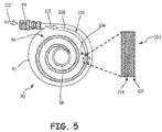
- FIG. 5 is a top cross-sectional view of spiral mist elimination system 90.
- Spiral mist elimination system 90 includes container 92 with inlet 94, layered assembly 96, and perforated tube 98.
- Layered assembly 96 includes mesh matrix 100.
- Mesh matrix 100 includes permeable layers 102 and mesh layers 104.
- first end 106 of mesh matrix 100 is positioned spirally inward from a spirally outward-most end 108 of layered assembly 96.
- This spirally off-set positioning of first end 106 of mesh matrix 100 enables first portion 110 of layered assembly 96 to collect a first set of droplets from engine bleed air 112 before engine bleed air 112 encounters mesh matrix 100.
- the further engine bleed air 112 travels along layered assembly 96 before running into mesh matrix 100 the greater the amount of droplets that are received by first portion 110 of layered assembly 96 through centrifugal separation as described above.
- the spirally off-set positioning of first end 106 of mesh matrix 100 can be adjusted to effectuate various performance characteristics of spiral mist elimination system 90 and the surrounding aircraft systems.
- a spiral mist elimination system may include a container with an inlet to receive engine bleed air into the container.
- the container may include a layered assembly in fluid communication with the inlet.
- the layered assembly may contain a spiral shape and may be concentric with a central axis of the container.
- the layered assembly may impart centrifugal motion in the engine bleed air as the engine bleed air travels spirally inward.
- a first portion of the layered assembly may force a first set of droplets in the bleed air toward an outer layer of the layered assembly.
- the first portion of the layered assembly may receive the first set of droplets.
- the layered assembly may also include a mesh matrix that collects a second set of droplets out of the engine bleed air.
- the second set of droplets may impact the mesh matrix and may coalesce to form a third set of droplets.
- a perforated tube may be disposed along the central axis of the container. The perforated tube may be in fluid communication with the layered assembly and may collect the engine bleed air from the layered assembly. Gravity may draw the first and third sets of droplets into a reservoir.
- spiral mist elimination system of the preceding paragraph can optionally include, additionally and/or alternatively, any one or more of the following features, configurations and/or additional components:
- a method of removing mist from an air flow may include inserting engine bleed air into a container through an inlet.
- the engine bleed air may be flowed into a first end of the layered assembly.
- the layered assembly may be in fluid communication with the inlet.
- the layered assembly may also include a spiral shape and may be concentric with a central axis of the container. Centrifugal motion may be imparted in the engine bleed air as the engine bleed air travels along a spiral flow-path through the layered assembly.
- a first set of fluid droplets may be forced toward an outer layer of the layered assembly and may be received by a first portion of the layered assembly.
- a second set of droplets may impact with a mesh matrix that is disposed within the layered assembly.
- the second set of droplets may coalesce into a third set of droplets.
- the engine bleed air may be drawn from the layered assembly into a perforated tube located along the central axis of the container.
- the perforated tube may be in fluid communication with the layered assembly.
- Gravity may draw the first and third sets of droplets into a reservoir where they may be collected.
- the method of removing mist from an air flow of the preceding paragraph can optionally include, additionally and/or alternatively, any one or more of the following features, configurations and/or additional components:
Landscapes
- Chemical & Material Sciences (AREA)
- Engineering & Computer Science (AREA)
- Chemical Kinetics & Catalysis (AREA)
- Combustion & Propulsion (AREA)
- Physics & Mathematics (AREA)
- Fluid Mechanics (AREA)
- Mechanical Engineering (AREA)
- General Engineering & Computer Science (AREA)
- Separating Particles In Gases By Inertia (AREA)
Applications Claiming Priority (1)
| Application Number | Priority Date | Filing Date | Title |
|---|---|---|---|
| US14/635,320 US9926854B2 (en) | 2015-03-02 | 2015-03-02 | Lightweight mist eliminator for aircraft fuel tank inerting systems |
Publications (2)
| Publication Number | Publication Date |
|---|---|
| EP3064263A1 true EP3064263A1 (fr) | 2016-09-07 |
| EP3064263B1 EP3064263B1 (fr) | 2018-09-19 |
Family
ID=55699325
Family Applications (1)
| Application Number | Title | Priority Date | Filing Date |
|---|---|---|---|
| EP16158196.2A Active EP3064263B1 (fr) | 2015-03-02 | 2016-03-02 | Éliminateur de brouillard léger pour systèmes d'injection de réservoir de carburant d'aéronef |
Country Status (2)
| Country | Link |
|---|---|
| US (1) | US9926854B2 (fr) |
| EP (1) | EP3064263B1 (fr) |
Cited By (1)
| Publication number | Priority date | Publication date | Assignee | Title |
|---|---|---|---|---|
| CN111298523A (zh) * | 2018-12-12 | 2020-06-19 | 中国石油化工股份有限公司 | 一种旋流除雾器 |
Families Citing this family (2)
| Publication number | Priority date | Publication date | Assignee | Title |
|---|---|---|---|---|
| WO2019027976A1 (fr) * | 2017-07-31 | 2019-02-07 | Carrier Corporation | Désorbeur pour système de climatisation ayant une déshumidification d'air à base de microémulsion intégrée |
| US20240157280A1 (en) * | 2021-08-04 | 2024-05-16 | Changxin Memory Technologies, Inc. | Dust collection device and plasma equipment |
Citations (4)
| Publication number | Priority date | Publication date | Assignee | Title |
|---|---|---|---|---|
| US4818257A (en) * | 1987-05-01 | 1989-04-04 | Monsanto Company | Fiber bed separator and process for removal of aerosols from high velocity gas without re-entrainment |
| US5151198A (en) * | 1990-09-11 | 1992-09-29 | The Dow Chemical Company | Method and apparatus for separating fluids using a carbonaceous polymeric filter having a LOI greater than 40 |
| EP2510997A1 (fr) * | 2005-01-07 | 2012-10-17 | Mecs, Inc. | Bande collectrice de fibres pour éliminateur de brouillard |
| WO2015143155A1 (fr) * | 2014-03-21 | 2015-09-24 | 3M Innovative Properties Company | Coalesceurs de gouttelettes |
Family Cites Families (26)
| Publication number | Priority date | Publication date | Assignee | Title |
|---|---|---|---|---|
| JPS5935642B2 (ja) * | 1978-05-22 | 1984-08-30 | 東レ株式会社 | 液体分離素子 |
| US4302356A (en) * | 1978-07-27 | 1981-11-24 | Chemical Research & Licensing Co. | Process for separating isobutene from C4 streams |
| US4471014A (en) * | 1981-06-30 | 1984-09-11 | Atomic Energy Of Canada Limited | Ordered bed packing module |
| US4842736A (en) * | 1988-09-06 | 1989-06-27 | Desalination Systems, Inc. | Spiral wound membrane |
| DE3842017A1 (de) * | 1988-12-14 | 1990-06-21 | Hermann Trabold | Oelfilter fuer verbrennungsmotoren |
| US5096584A (en) * | 1990-01-29 | 1992-03-17 | The Dow Chemical Company | Spiral-wound membrane separation device with feed and permeate/sweep fluid flow control |
| US5120331A (en) * | 1990-02-06 | 1992-06-09 | Keith Landy | Composite gas filtering unit |
| US5147541A (en) * | 1990-11-14 | 1992-09-15 | Koch Membrane Systems, Inc. | Spiral filtration module with strengthened membrane leaves and method of constructing same |
| US5114582A (en) * | 1991-04-12 | 1992-05-19 | W. R. Grace & Co.-Conn. | Filter element and spiral-wound membrane cartridge containing same |
| WO1993022038A1 (fr) * | 1992-05-01 | 1993-11-11 | Filmtec Corporation | Element de membrane enroule en spirale |
| CA2230865C (fr) * | 1995-09-06 | 2004-03-23 | Universal Air Technology, Inc. | Desinfection photocatalytique de l'air |
| US6224767B1 (en) * | 1998-03-20 | 2001-05-01 | Toray Industries Inc. | Fluid separation element assembly |
| WO2001087364A1 (fr) * | 2000-05-18 | 2001-11-22 | Sharp Kabushiki Kaisha | Procede de sterilisation, element generateur d'ions, dispositif generateur d'ions et dispositif de conditionnement d'air |
| ATE439873T1 (de) * | 2000-08-28 | 2009-09-15 | Sharp Kk | Klimaanlage und dafür verwendeter ionengenerator |
| US6398833B1 (en) | 2000-11-06 | 2002-06-04 | Pratt & Whitney Canada Corp. | Air/oil separator |
| US6881336B2 (en) * | 2002-05-02 | 2005-04-19 | Filmtec Corporation | Spiral wound element with improved feed space |
| US20040255515A1 (en) * | 2002-06-14 | 2004-12-23 | Fenton Ronald L. | Method and apparatus for improving fuel combustion |
| US7250141B2 (en) * | 2004-02-27 | 2007-07-31 | Honeywell International, Inc. | Augmented catalytic heat exchanger system |
| US6957569B1 (en) | 2004-04-15 | 2005-10-25 | Hamilton Sundstrand Corporation | Detection of oil in turbine engine bleed air |
| DE202005010445U1 (de) * | 2005-06-30 | 2006-11-16 | Mann + Hummel Gmbh | Filteranordnung für Flüssigkeiten |
| US20070251883A1 (en) * | 2006-04-28 | 2007-11-01 | Niu Q Jason | Reverse Osmosis Membrane with Branched Poly(Alkylene Oxide) Modified Antifouling Surface |
| US7753172B2 (en) | 2007-02-13 | 2010-07-13 | Rolls-Royce Corporation | Lubricant sump with metal foam diffuser |
| US7857882B1 (en) | 2007-12-13 | 2010-12-28 | Johnson Welded Products Inc. | Water and oil mist elimination apparatus for a vehicular compressed air storage system |
| WO2011119280A1 (fr) * | 2010-03-24 | 2011-09-29 | Dow Global Technologies Llc | Module de filtration enroulé en spirale |
| US8601826B2 (en) | 2011-01-20 | 2013-12-10 | Hamilton Sundstrand Corporation | Recirculation heat exchanger outlet header |
| US8500869B1 (en) | 2012-06-21 | 2013-08-06 | Hamilton Sundstrand Corporation | Anti-rotation deaerator outlet diffuser |
-
2015
- 2015-03-02 US US14/635,320 patent/US9926854B2/en active Active
-
2016
- 2016-03-02 EP EP16158196.2A patent/EP3064263B1/fr active Active
Patent Citations (4)
| Publication number | Priority date | Publication date | Assignee | Title |
|---|---|---|---|---|
| US4818257A (en) * | 1987-05-01 | 1989-04-04 | Monsanto Company | Fiber bed separator and process for removal of aerosols from high velocity gas without re-entrainment |
| US5151198A (en) * | 1990-09-11 | 1992-09-29 | The Dow Chemical Company | Method and apparatus for separating fluids using a carbonaceous polymeric filter having a LOI greater than 40 |
| EP2510997A1 (fr) * | 2005-01-07 | 2012-10-17 | Mecs, Inc. | Bande collectrice de fibres pour éliminateur de brouillard |
| WO2015143155A1 (fr) * | 2014-03-21 | 2015-09-24 | 3M Innovative Properties Company | Coalesceurs de gouttelettes |
Cited By (1)
| Publication number | Priority date | Publication date | Assignee | Title |
|---|---|---|---|---|
| CN111298523A (zh) * | 2018-12-12 | 2020-06-19 | 中国石油化工股份有限公司 | 一种旋流除雾器 |
Also Published As
| Publication number | Publication date |
|---|---|
| EP3064263B1 (fr) | 2018-09-19 |
| US20160258362A1 (en) | 2016-09-08 |
| US9926854B2 (en) | 2018-03-27 |
Similar Documents
| Publication | Publication Date | Title |
|---|---|---|
| US9005340B2 (en) | Fiber bed assembly including a re-entrainment control device for a fiber bed mist eliminator | |
| EP2941318B1 (fr) | Cyclone, éliminateur de brouillard à cyclone et procédé d'utilisation | |
| CN104540570B (zh) | 惯性气液分离器及用在惯性气液分离器中的多孔收集基体 | |
| EP1998868B1 (fr) | Procede et moyen de generer simultanement une mousse aqueuse et de nombreuses microgouttelettes pour utilisation dans le filtrage d'un courant d'air contamine | |
| EP0353903B1 (fr) | Procédé de séparation et filtration des systèmes gaz-liquide | |
| US5112375A (en) | Radial vane demisting system in a separator for removing entrained droplets from a gas stream | |
| US20130312609A1 (en) | Apparatus and methods for filtration of solid particles and separation of liquid droplets and liquid aerosols from a gas stream | |
| US7837752B2 (en) | Water removal downstream of a turbine | |
| EP3064263B1 (fr) | Éliminateur de brouillard léger pour systèmes d'injection de réservoir de carburant d'aéronef | |
| CN102000461A (zh) | 纤维床组件和用于该纤维床组件的纤维床 | |
| US8858669B2 (en) | Oil coalescing filter | |
| US10792604B2 (en) | Horizontal coalescing filter | |
| WO2010014301A1 (fr) | Séparateur gaz-liquide avec impact et coalescence en double flux | |
| US9511316B2 (en) | System for extending turndown in a gas-liquid separator | |
| WO2010091439A1 (fr) | Séparateur liquide/gaz | |
| AU665211B2 (en) | Conical coalescing filter | |
| CN102228765A (zh) | 改进的波纹板结构 | |
| RU2203125C1 (ru) | Сепаратор тонкодисперсной капельной жидкости | |
| EP0898492A1 (fr) | Coalesceur jetable | |
| EP4241868A1 (fr) | Élément de filtre, cartouche et système de filtre | |
| EP4154965B1 (fr) | Séparateur de phase passif avec chambre d'élimination de liquide | |
| CN220003437U (zh) | 除雾装置和除雾系统 | |
| EP4129447B1 (fr) | Séparateur de phase passif au niveau de la sortie d'un échangeur de chaleur | |
| RU156530U1 (ru) | Сепаратор-маслоотделитель | |
| EP3116624A1 (fr) | Séparateur d'huile pour installations de refroidissement et/ou de climatisation |
Legal Events
| Date | Code | Title | Description |
|---|---|---|---|
| PUAI | Public reference made under article 153(3) epc to a published international application that has entered the european phase |
Free format text: ORIGINAL CODE: 0009012 |
|
| AK | Designated contracting states |
Kind code of ref document: A1 Designated state(s): AL AT BE BG CH CY CZ DE DK EE ES FI FR GB GR HR HU IE IS IT LI LT LU LV MC MK MT NL NO PL PT RO RS SE SI SK SM TR |
|
| AX | Request for extension of the european patent |
Extension state: BA ME |
|
| STAA | Information on the status of an ep patent application or granted ep patent |
Free format text: STATUS: REQUEST FOR EXAMINATION WAS MADE |
|
| 17P | Request for examination filed |
Effective date: 20170307 |
|
| RBV | Designated contracting states (corrected) |
Designated state(s): AL AT BE BG CH CY CZ DE DK EE ES FI FR GB GR HR HU IE IS IT LI LT LU LV MC MK MT NL NO PL PT RO RS SE SI SK SM TR |
|
| REG | Reference to a national code |
Ref country code: DE Ref legal event code: R079 Ref document number: 602016005626 Country of ref document: DE Free format text: PREVIOUS MAIN CLASS: B01D0039160000 Ipc: F02C0009180000 |
|
| GRAP | Despatch of communication of intention to grant a patent |
Free format text: ORIGINAL CODE: EPIDOSNIGR1 |
|
| STAA | Information on the status of an ep patent application or granted ep patent |
Free format text: STATUS: GRANT OF PATENT IS INTENDED |
|
| RIC1 | Information provided on ipc code assigned before grant |
Ipc: B01D 45/16 20060101ALI20180227BHEP Ipc: F02C 9/18 20060101AFI20180227BHEP Ipc: B01D 39/16 20060101ALI20180227BHEP |
|
| INTG | Intention to grant announced |
Effective date: 20180323 |
|
| GRAS | Grant fee paid |
Free format text: ORIGINAL CODE: EPIDOSNIGR3 |
|
| GRAA | (expected) grant |
Free format text: ORIGINAL CODE: 0009210 |
|
| STAA | Information on the status of an ep patent application or granted ep patent |
Free format text: STATUS: THE PATENT HAS BEEN GRANTED |
|
| AK | Designated contracting states |
Kind code of ref document: B1 Designated state(s): AL AT BE BG CH CY CZ DE DK EE ES FI FR GB GR HR HU IE IS IT LI LT LU LV MC MK MT NL NO PL PT RO RS SE SI SK SM TR |
|
| REG | Reference to a national code |
Ref country code: GB Ref legal event code: FG4D |
|
| REG | Reference to a national code |
Ref country code: CH Ref legal event code: EP |
|
| REG | Reference to a national code |
Ref country code: AT Ref legal event code: REF Ref document number: 1043514 Country of ref document: AT Kind code of ref document: T Effective date: 20181015 |
|
| REG | Reference to a national code |
Ref country code: IE Ref legal event code: FG4D |
|
| REG | Reference to a national code |
Ref country code: DE Ref legal event code: R096 Ref document number: 602016005626 Country of ref document: DE |
|
| REG | Reference to a national code |
Ref country code: NL Ref legal event code: MP Effective date: 20180919 |
|
| PG25 | Lapsed in a contracting state [announced via postgrant information from national office to epo] |
Ref country code: SE Free format text: LAPSE BECAUSE OF FAILURE TO SUBMIT A TRANSLATION OF THE DESCRIPTION OR TO PAY THE FEE WITHIN THE PRESCRIBED TIME-LIMIT Effective date: 20180919 Ref country code: NO Free format text: LAPSE BECAUSE OF FAILURE TO SUBMIT A TRANSLATION OF THE DESCRIPTION OR TO PAY THE FEE WITHIN THE PRESCRIBED TIME-LIMIT Effective date: 20181219 Ref country code: BG Free format text: LAPSE BECAUSE OF FAILURE TO SUBMIT A TRANSLATION OF THE DESCRIPTION OR TO PAY THE FEE WITHIN THE PRESCRIBED TIME-LIMIT Effective date: 20181219 Ref country code: RS Free format text: LAPSE BECAUSE OF FAILURE TO SUBMIT A TRANSLATION OF THE DESCRIPTION OR TO PAY THE FEE WITHIN THE PRESCRIBED TIME-LIMIT Effective date: 20180919 Ref country code: LT Free format text: LAPSE BECAUSE OF FAILURE TO SUBMIT A TRANSLATION OF THE DESCRIPTION OR TO PAY THE FEE WITHIN THE PRESCRIBED TIME-LIMIT Effective date: 20180919 Ref country code: FI Free format text: LAPSE BECAUSE OF FAILURE TO SUBMIT A TRANSLATION OF THE DESCRIPTION OR TO PAY THE FEE WITHIN THE PRESCRIBED TIME-LIMIT Effective date: 20180919 Ref country code: GR Free format text: LAPSE BECAUSE OF FAILURE TO SUBMIT A TRANSLATION OF THE DESCRIPTION OR TO PAY THE FEE WITHIN THE PRESCRIBED TIME-LIMIT Effective date: 20181220 |
|
| REG | Reference to a national code |
Ref country code: LT Ref legal event code: MG4D |
|
| PG25 | Lapsed in a contracting state [announced via postgrant information from national office to epo] |
Ref country code: AL Free format text: LAPSE BECAUSE OF FAILURE TO SUBMIT A TRANSLATION OF THE DESCRIPTION OR TO PAY THE FEE WITHIN THE PRESCRIBED TIME-LIMIT Effective date: 20180919 Ref country code: LV Free format text: LAPSE BECAUSE OF FAILURE TO SUBMIT A TRANSLATION OF THE DESCRIPTION OR TO PAY THE FEE WITHIN THE PRESCRIBED TIME-LIMIT Effective date: 20180919 Ref country code: HR Free format text: LAPSE BECAUSE OF FAILURE TO SUBMIT A TRANSLATION OF THE DESCRIPTION OR TO PAY THE FEE WITHIN THE PRESCRIBED TIME-LIMIT Effective date: 20180919 |
|
| REG | Reference to a national code |
Ref country code: AT Ref legal event code: MK05 Ref document number: 1043514 Country of ref document: AT Kind code of ref document: T Effective date: 20180919 |
|
| PG25 | Lapsed in a contracting state [announced via postgrant information from national office to epo] |
Ref country code: IT Free format text: LAPSE BECAUSE OF FAILURE TO SUBMIT A TRANSLATION OF THE DESCRIPTION OR TO PAY THE FEE WITHIN THE PRESCRIBED TIME-LIMIT Effective date: 20180919 Ref country code: EE Free format text: LAPSE BECAUSE OF FAILURE TO SUBMIT A TRANSLATION OF THE DESCRIPTION OR TO PAY THE FEE WITHIN THE PRESCRIBED TIME-LIMIT Effective date: 20180919 Ref country code: NL Free format text: LAPSE BECAUSE OF FAILURE TO SUBMIT A TRANSLATION OF THE DESCRIPTION OR TO PAY THE FEE WITHIN THE PRESCRIBED TIME-LIMIT Effective date: 20180919 Ref country code: CZ Free format text: LAPSE BECAUSE OF FAILURE TO SUBMIT A TRANSLATION OF THE DESCRIPTION OR TO PAY THE FEE WITHIN THE PRESCRIBED TIME-LIMIT Effective date: 20180919 Ref country code: AT Free format text: LAPSE BECAUSE OF FAILURE TO SUBMIT A TRANSLATION OF THE DESCRIPTION OR TO PAY THE FEE WITHIN THE PRESCRIBED TIME-LIMIT Effective date: 20180919 Ref country code: RO Free format text: LAPSE BECAUSE OF FAILURE TO SUBMIT A TRANSLATION OF THE DESCRIPTION OR TO PAY THE FEE WITHIN THE PRESCRIBED TIME-LIMIT Effective date: 20180919 Ref country code: ES Free format text: LAPSE BECAUSE OF FAILURE TO SUBMIT A TRANSLATION OF THE DESCRIPTION OR TO PAY THE FEE WITHIN THE PRESCRIBED TIME-LIMIT Effective date: 20180919 Ref country code: IS Free format text: LAPSE BECAUSE OF FAILURE TO SUBMIT A TRANSLATION OF THE DESCRIPTION OR TO PAY THE FEE WITHIN THE PRESCRIBED TIME-LIMIT Effective date: 20190119 Ref country code: PL Free format text: LAPSE BECAUSE OF FAILURE TO SUBMIT A TRANSLATION OF THE DESCRIPTION OR TO PAY THE FEE WITHIN THE PRESCRIBED TIME-LIMIT Effective date: 20180919 |
|
| PG25 | Lapsed in a contracting state [announced via postgrant information from national office to epo] |
Ref country code: PT Free format text: LAPSE BECAUSE OF FAILURE TO SUBMIT A TRANSLATION OF THE DESCRIPTION OR TO PAY THE FEE WITHIN THE PRESCRIBED TIME-LIMIT Effective date: 20190119 Ref country code: SK Free format text: LAPSE BECAUSE OF FAILURE TO SUBMIT A TRANSLATION OF THE DESCRIPTION OR TO PAY THE FEE WITHIN THE PRESCRIBED TIME-LIMIT Effective date: 20180919 Ref country code: SM Free format text: LAPSE BECAUSE OF FAILURE TO SUBMIT A TRANSLATION OF THE DESCRIPTION OR TO PAY THE FEE WITHIN THE PRESCRIBED TIME-LIMIT Effective date: 20180919 |
|
| REG | Reference to a national code |
Ref country code: DE Ref legal event code: R097 Ref document number: 602016005626 Country of ref document: DE |
|
| PLBE | No opposition filed within time limit |
Free format text: ORIGINAL CODE: 0009261 |
|
| STAA | Information on the status of an ep patent application or granted ep patent |
Free format text: STATUS: NO OPPOSITION FILED WITHIN TIME LIMIT |
|
| PG25 | Lapsed in a contracting state [announced via postgrant information from national office to epo] |
Ref country code: DK Free format text: LAPSE BECAUSE OF FAILURE TO SUBMIT A TRANSLATION OF THE DESCRIPTION OR TO PAY THE FEE WITHIN THE PRESCRIBED TIME-LIMIT Effective date: 20180919 |
|
| 26N | No opposition filed |
Effective date: 20190620 |
|
| REG | Reference to a national code |
Ref country code: DE Ref legal event code: R119 Ref document number: 602016005626 Country of ref document: DE |
|
| PG25 | Lapsed in a contracting state [announced via postgrant information from national office to epo] |
Ref country code: SI Free format text: LAPSE BECAUSE OF FAILURE TO SUBMIT A TRANSLATION OF THE DESCRIPTION OR TO PAY THE FEE WITHIN THE PRESCRIBED TIME-LIMIT Effective date: 20180919 Ref country code: MC Free format text: LAPSE BECAUSE OF FAILURE TO SUBMIT A TRANSLATION OF THE DESCRIPTION OR TO PAY THE FEE WITHIN THE PRESCRIBED TIME-LIMIT Effective date: 20180919 |
|
| REG | Reference to a national code |
Ref country code: CH Ref legal event code: PL |
|
| PG25 | Lapsed in a contracting state [announced via postgrant information from national office to epo] |
Ref country code: LU Free format text: LAPSE BECAUSE OF NON-PAYMENT OF DUE FEES Effective date: 20190302 |
|
| REG | Reference to a national code |
Ref country code: BE Ref legal event code: MM Effective date: 20190331 |
|
| PG25 | Lapsed in a contracting state [announced via postgrant information from national office to epo] |
Ref country code: CH Free format text: LAPSE BECAUSE OF NON-PAYMENT OF DUE FEES Effective date: 20190331 Ref country code: DE Free format text: LAPSE BECAUSE OF NON-PAYMENT OF DUE FEES Effective date: 20191001 Ref country code: IE Free format text: LAPSE BECAUSE OF NON-PAYMENT OF DUE FEES Effective date: 20190302 Ref country code: LI Free format text: LAPSE BECAUSE OF NON-PAYMENT OF DUE FEES Effective date: 20190331 |
|
| PG25 | Lapsed in a contracting state [announced via postgrant information from national office to epo] |
Ref country code: BE Free format text: LAPSE BECAUSE OF NON-PAYMENT OF DUE FEES Effective date: 20190331 |
|
| PG25 | Lapsed in a contracting state [announced via postgrant information from national office to epo] |
Ref country code: TR Free format text: LAPSE BECAUSE OF FAILURE TO SUBMIT A TRANSLATION OF THE DESCRIPTION OR TO PAY THE FEE WITHIN THE PRESCRIBED TIME-LIMIT Effective date: 20180919 |
|
| PG25 | Lapsed in a contracting state [announced via postgrant information from national office to epo] |
Ref country code: MT Free format text: LAPSE BECAUSE OF NON-PAYMENT OF DUE FEES Effective date: 20190302 |
|
| PG25 | Lapsed in a contracting state [announced via postgrant information from national office to epo] |
Ref country code: CY Free format text: LAPSE BECAUSE OF FAILURE TO SUBMIT A TRANSLATION OF THE DESCRIPTION OR TO PAY THE FEE WITHIN THE PRESCRIBED TIME-LIMIT Effective date: 20180919 |
|
| PG25 | Lapsed in a contracting state [announced via postgrant information from national office to epo] |
Ref country code: HU Free format text: LAPSE BECAUSE OF FAILURE TO SUBMIT A TRANSLATION OF THE DESCRIPTION OR TO PAY THE FEE WITHIN THE PRESCRIBED TIME-LIMIT; INVALID AB INITIO Effective date: 20160302 |
|
| PG25 | Lapsed in a contracting state [announced via postgrant information from national office to epo] |
Ref country code: MK Free format text: LAPSE BECAUSE OF FAILURE TO SUBMIT A TRANSLATION OF THE DESCRIPTION OR TO PAY THE FEE WITHIN THE PRESCRIBED TIME-LIMIT Effective date: 20180919 |
|
| P01 | Opt-out of the competence of the unified patent court (upc) registered |
Effective date: 20230522 |
|
| PGFP | Annual fee paid to national office [announced via postgrant information from national office to epo] |
Ref country code: FR Payment date: 20250218 Year of fee payment: 10 |
|
| PGFP | Annual fee paid to national office [announced via postgrant information from national office to epo] |
Ref country code: GB Payment date: 20250221 Year of fee payment: 10 |