EP3064367B1 - Procede et dispositif pour le marouflage d'une couverture de livre sur la surface exterieure encollee d'un bloc de livre - Google Patents
Procede et dispositif pour le marouflage d'une couverture de livre sur la surface exterieure encollee d'un bloc de livre Download PDFInfo
- Publication number
- EP3064367B1 EP3064367B1 EP16000500.5A EP16000500A EP3064367B1 EP 3064367 B1 EP3064367 B1 EP 3064367B1 EP 16000500 A EP16000500 A EP 16000500A EP 3064367 B1 EP3064367 B1 EP 3064367B1
- Authority
- EP
- European Patent Office
- Prior art keywords
- book
- rub
- down rollers
- adjusting
- rollers
- Prior art date
- Legal status (The legal status is an assumption and is not a legal conclusion. Google has not performed a legal analysis and makes no representation as to the accuracy of the status listed.)
- Active
Links
Images

Classifications
-
- B—PERFORMING OPERATIONS; TRANSPORTING
- B42—BOOKBINDING; ALBUMS; FILES; SPECIAL PRINTED MATTER
- B42C—BOOKBINDING
- B42C19/00—Multi-step processes for making books
-
- B—PERFORMING OPERATIONS; TRANSPORTING
- B42—BOOKBINDING; ALBUMS; FILES; SPECIAL PRINTED MATTER
- B42C—BOOKBINDING
- B42C11/00—Casing-in
- B42C11/04—Machines or equipment for casing-in or applying covers to books
-
- B—PERFORMING OPERATIONS; TRANSPORTING
- B42—BOOKBINDING; ALBUMS; FILES; SPECIAL PRINTED MATTER
- B42C—BOOKBINDING
- B42C9/00—Applying glue or adhesive peculiar to bookbinding
- B42C9/0006—Applying glue or adhesive peculiar to bookbinding by applying adhesive to a stack of sheets
- B42C9/0012—Applying glue or adhesive peculiar to bookbinding by applying adhesive to a stack of sheets with a roller
- B42C9/0031—Applying glue or adhesive peculiar to bookbinding by applying adhesive to a stack of sheets with a roller with continuous flow of stacks of sheets
- B42C9/0037—Applying glue or adhesive peculiar to bookbinding by applying adhesive to a stack of sheets with a roller with continuous flow of stacks of sheets and subsequently applying a cover
Definitions
- the present invention relates to a method for rubbing a book cover on the glued outer surfaces of a book block according to the features of the preamble of claim 1 and an apparatus having the features of the preamble of claim 5 for carrying out the method.
- Hanging machines or book streets are known. These have a oriented in a vertical plane conveyor in the manner of a continuously rotating paternoster with saddle plates as transport elements.
- a book block is opened in the middle with the back up pointing astride one of these saddle plates pushed and transported by this in a first conveyor section.
- the book block is guided along a gluing unit with applicator rollers arranged on both sides of the transport path, the applicator rollers applying the adhesive to the outer surfaces of the book block, which are usually formed by so-called attachments.
- this gluing unit there is a support plane formed of bars, on each of which a book cover is provided with the outside pointing upwards and aligned with its back region to the book block back.
- the book block glued to the side surfaces plunges with its back into the back area of the book cover and lifts it from its provision position, wherein the cover of the book cover at the back region starting at the side surfaces of the book block fold.
- a grater with a pair of gripping rollers.
- the grater is vertically movable and comprises such a drive that it moves vertically starting in a lower starting position and thereby synchronized in a section with the fifth wheels of the circulating conveyor the back region of the Book cover supports before reversing its direction of movement in an upper end position.
- the Anreibewalzen roll on the outer surfaces of the book cover, while rubbing it against the book block and finally reach their lower starting position.
- the Anreibewalzen are stored horizontally positioned in the grinder.
- the adjustment is carried out via spindles symmetrical to the plane spanned by the fifth wheel plates of the circulating conveyor plane.
- a controllable drive of this thickness adjustment allows automated setup. Without operator intervention, the selected thickness setting is maintained throughout the production. Since the book thickness can vary slightly from book to book as well as within a book, the Anreibewalzen are spring-loaded, whereby damage to the grater when misadjustment can be avoided.
- the gripping force is determined by the spring rate and the degree of deflection. Since the variations in thickness actually occurring during the grinding are not exactly predictable, the acting rubbing force is only exactly known on average.
- the object of the present invention is therefore to provide a method and a device for the grinding of a book cover on the glued outer surfaces of a book block available, which are exempt from the disadvantages mentioned.
- the invention provides a method according to the characterizing features of claim 1 and a device according to the characterizing features of claim 5.
- the features of the dependent claims describe advantageous embodiments of the invention.
- the known feed motion of the feed rollers is regulated, wherein different control variables are used in different sections of the vertical movement of the grinder.
- the feed movement of the Anreibewalzen is position-controlled, so that the horizontal position of the Anreibewalzen, i. the position regarding the book thickness controlled variable.
- the gripping rollers can be positioned so accurately that the back portion of the book cover, as long as it is between them, positioned in the lateral direction exactly to the book block back and during the synchronized to the movement of the saddle plates upward movement of the grater is performed. A breaking of the reinforced by a Schränz back portion of the book cover from this guided position can be prevented.
- the feeding device of the Anreibewalzen includes as feedback a sensor system for determining the current horizontal position of the Anreibewalzen, which is connected via a corresponding data line to the same control of the device, which also controls the adjustment of the feed device.
- the required encoder can be integrated in the adjustment itself.
- the feed movement of the gripping rollers is controlled by controlled force is used as a control variable applied by the gripping rollers on the book force. In this way, the force exerted during the grinding can be predetermined and precisely maintained.
- the feed device as feedback comprises a sensor system for determining the momentarily acting on the Anreibewalzen reaction force, which is connected via a corresponding data line with the mentioned control of the device.
- a sensor system and the adjustment itself can be used, so that no additional encoder is required.
- the change takes place between position control of the feed device on the one hand and its force control on the other hand and vice versa based on the relative position of the Anreibewalzen to the respective fifth wheel plate in the vertical direction and / or their temporal change.
- the circulation conveyor is equipped with a transmitter, in a particularly simple manner a rotary encoder, which is connected to the adjusting drive of the delivery device-driving control.
- the position control and / or the force control of the feed movement takes place on the basis of desired value curves, so that a non-uniform course of the feed movement is made possible. In this way, vibrations in the feed movement and, in particular, in the case of the laterally projecting back region of the book cover, a hard impact of the feed rollers on the book covers can be avoided.
- the drive of the feed device by a servo motor which is suitable for both a position control and for a force control, so that the actuator does not need to be divided into two differently operating systems needs.
- servomotors provide their control units with data that can be interpreted as a position, as well as those that can be interpreted as moment or force, so that separate encoders can be dispensed with. In this way, the drive of the delivery device can be kept extremely compact.
- the equipment of the grinder with a delivery device with its own drive and its own control loop per Anreibewalze is particularly advantageous.
- the grater also intended asymmetric hooking or one-sided rubbing.
- the block next to pages of paper also contain covers for digital data carriers, whereby the focus of the block is outside its center plane and the block advantageous in Area of the center of gravity instead of the geometric center of the fifth wheel plate is worn to avoid lateral slippage.
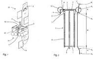
- FIG. 1 shows schematically a device for hanging books with a working according to the principle of a paternoster circulation conveyor 23, the fifth wheel plates 9 are continuously moved by a common traction means in a vertical plane without changing their spatial orientation in a transport direction d.
- the previously supplied to the circulation conveyor 23, opened in the region of its center of gravity book block 1 is astride detected by a fifth wheel plate 9.
- the in Fig. 1 Book block 1 has almost completely passed through the gluing unit 24 and emerges with its back 2 straight into the back area of the book cover 5 which has been stretched out and aligned on a support 22. Above this support 22 is a pair of gripping rollers 10 a trimmer.
- the book cover 5 is raised by the book block back 2 from its provision position on the support 22, so that the cover book cover 6 completely abut the glued side surfaces 3 of the book block 1. Meanwhile, the rubbing device moves synchronously with the saddle plate 9, so that the back portion of the book cover 5 is held and guided in alignment by the rubbing rollers positioned on both sides.
- the grater as in Fig. 3 shown constructed in a frame 11 which is mounted vertically movable on a bearing mounted in the machine frame not shown guide column 12 and secured by also not shown guide surfaces rolling rollers 13 against rotation about the guide column 12.
- the Movement of the grinder along this guide column 12 is generated by a drive, not shown, which is designed in a familiar to the expert.
- Both gripping rollers 10 are adjustable by a correction device 20 in its vertical position to the frame 11 and also to each other.
- a correction device 20 in its vertical position to the frame 11 and also to each other.
- the position of the Anreibewalzen 10 can be corrected to the back region of the book cover 5 during the synchronous movement section.
- manufacturing tolerances of the device as well as in the production of the book blocks 1 and the book covers 5 occurring systemic shape errors of the back areas can be compensated.
- the Anreibewalzen 10 are mounted on linear guides 14 in a horizontal plane at a distance movable, and their feed motion b via a feed device 21 from the linear guides 14 parallel spindle drives 15.
- Linear guide 14 and spindle drive 15 are each on both sides of each Anreibewalze 10, wherein the same Anreibewalze 10 associated spindle drives 15 are operated synchronously via a drive connection 16.
- the feed device 21 is driven by an electric motor 19.
- a servo motor is used, which forms a control loop with the controller 26 of the device, which is closed by data lines 25.
- the data transmitted by the motor 19 to the controller 26 includes information interpreted by the controller 26 as the instantaneous position of the gripper rollers 10 with respect to their feed motion b and as applied by the Anreibewalzen 10 on the book cover 5 rubbing force and so as actual values for the control the delivery movement b are used.
- Each dressing roller 10 is assigned its own feed device 21, each with its own drive and control circuit, in order to allow in a particularly simple manner an off-center transport through the saddle plates 9 in asymmetric products.
- a combination of a position-adjustable first and a force-controllable second drive can be used as the drive of the feed device, such as, for example, a simple electric motor positioning drive superimposed with a pneumatic cylinder.
- a simple electric motor positioning drive superimposed with a pneumatic cylinder.
- Such a drive combination can be constructed event-controlled and therefore requires a less complex control 26, as required by the use of substantially variable usable servomotors 19.
- FIG. 2 An exemplary sequence of motion of the Anreibewalzen 10 is in Fig. 2 shown schematically.
- the grater is located in the saddle plate 9 synchronous upward movement corresponding to the transport direction d.
- the book cover 6 are already fully folded to the book block 1.
- the stabilized by the Schrenz 7 back portion of the book cover 5 is located between the gripping rollers 10 of the gripper and is aligned and guided by these laterally to the book block spine 2.
- the in the in Fig. 2 shown left Anreibewalze 10 arrows show the direction of the feed movement b of the gripper roller, each of which runs horizontally to the fifth wheel plate 9 pointing, and Anreibefar a the grater, which is the transport movement d counter-directed vertically downwards.
- Anreibewalze 10 shown extending their trajectory c is shown relative to the book block 1. This can be broken down into the gripping movement a and the infeed movement b .
- the movement path is subdivided into areas A, B in which the feed movement b of the gripping rollers 10 is alternately position-regulated and force-controlled.
- Section A indicates the area with the delivery position as a control variable, which in turn can be subdivided into sections with constant setpoint input A 2 , A 5 and transition areas A 1, A 3 , A 4 , where changes in the setpoint occur.
- Section B shows the force-controlled region of the movement path c of the Anreibewalze 10, in which changes in the delivery position occur only with changes in the cross section or the rigidity of the book, as long as the target value is kept constant.
- the region B marked by the force control of the feed movement b extends over the region of the gripping movement a , in which the book covers 6 are supported by the book block 1 in order to avoid damage to their edges projecting beyond the book block 1.
Landscapes
- Engineering & Computer Science (AREA)
- Mechanical Engineering (AREA)
- Delivering By Means Of Belts And Rollers (AREA)
- Grinding Of Cylindrical And Plane Surfaces (AREA)
Claims (9)
- Procédé d'application de la couverture de livres, lors duquel• des blocs de livres (1) sont transportés à califourchon au moyen de plaques cavalières (9) s'engageant dans les blocs de livres (1) d'un convoyeur rotatif (23) et à cet effet, sont encollés sur les surfaces latérales (3) dans un premier tronçon de convoyage,• dans un deuxième tronçon de convoyage, sont plongés respectivement dans la zone dorsale d'une couverture de livre (5) mise à disposition en étant couchée sensiblement en étalement sur un support (22) et dans leur déplacement de transport continu, relèvent la couverture de livre (5) de sa position de repos et l'entraînent, de telle sorte que les couvercles (6) de la couverture de livre soient adjacents aux surfaces latérales (3) encollées des blocs de livres (1),• dans un premier tronçon secondaire, un système doté de cylindres de marouflage (10) pour maroufler les couvercles (6) sur les surfaces latérales (3) se déplaçant de manière synchrone avec la plaque cavalière (9) et par un déplacement de mise en prise (b), les cylindres de marouflage (10) étant positionnés en accord avec l'épaisseur des livres de telle sorte qu'ils soutiennent la zone dorsale de la couverture de livre (5) au moins jusqu'à ce que la couverture de livre (5) soit libérée du support (22) et• dans un deuxième tronçon secondaire successif, dans un déplacement de marouflage (a) à l'encontre de la direction de transport (d) des blocs de livres (1), le système de marouflage se déplaçant par rapport à la couverture de livre (5), les cylindres de marouflage (10) se déroulant sur les surfaces extérieures des couvercles (6) et marouflant de ce fait ces derniers sur les surfaces latérales (3) des blocs de livres (1),caractérisé en ce que,• pour chaque cycle de travail du dispositif de marouflage, le déplacement de mise en prise (b) des cylindres de marouflage (10) se divise en au moins deux parties (A, B), pour lesquelles dans au moins une première partie (A), le déplacement de mise en prise (b) s'effectue en réglage de position et dans au moins une partie supplémentaire (B), le déplacement de mise en prise (b) s'effectue en réglage de force, pendant la première partie (A), le système de commande (26) du dispositif de marouflage interprétant les informations mises à disposition par un première système de capteurs via une ligne de données (25) en tant que position horizontale momentanée des cylindres de marouflage (10) et pendant la partie supplémentaire (B), interprétant les informations mises à disposition par un deuxième système de capteurs via une ligne de données (25) en tant que force exercée sur le livre par les cylindres de marouflage (10).
- Procédé selon la revendication 1, caractérisé en ce que le changement entre les parties (A, B) avec déplacement de mise en prise (b) en réglage de position d'une part et déplacement de mise en prise (b) en réglage de force d'autre part et/ou inversement, s'effectue en fonction d'une position déterminée des plaques cavalières (9) dans leur direction de transport (d).
- Procédé selon la revendication 1 ou 2, caractérisé en ce que lorsqu'un refus d'épuration (7) d'une couverture de livre (5) se trouve entre les cylindres de marouflage (10) d'une paire, le déplacement de mise en prise desdits cylindres de marouflage (10) s'effectue en réglage de position.
- Procédé selon l'une quelconque des revendications 1 à 3, caractérisé en ce que lorsqu'un bloc de livre (1) et des couvercles (6) d'une couverture de livre (5) se trouvent entre les cylindres de marouflage (10) d'une paire, le déplacement de mise en prise (b) desdits cylindres de marouflage (10) s'effectue en réglage de force.
- Dispositif destiné à réaliser le procédé selon au moins l'une quelconque des revendications 1 à 4, comportant au moins :• un convoyeur rotatif (23) avec des plaques cavalières (9) s'engageant dans les blocs de livres (1) et transportant ces derniers à califourchon dans un plan vertical,• un dispositif d'encollage (24) placé le long du trajet de convoyage des blocs de livres (1) formé par le convoyeur rotatif (23) pour encoller les surfaces latérales (3) des blocs de livres (1) transportés le long du dispositif d'encollage (24),• un dispositif de marouflage des couvercles (6) des couvertures de livres (5) monté en aval du dispositif d'encollage (24) dans la direction de transport (d) des blocs de livres (1) pour maroufler les couvercles (6) sur les surfaces latérales (3) encollées des blocs de livres (1), avec au moins une paire de cylindres de marouflage (10), lesquels sont placés en vis-à-vis de part et d'autre du trajet de convoyage des blocs de livres (1),• les cylindres de marouflage (10) étant logés de manière mobile, à la parallèle d'au moins un tronçon du trajet de convoyage des blocs de livres (1) et• le dispositif de marouflage comprenant au moins un dispositif de mise en prise (21) pour ajuster l'écart mutuel entre les cylindres de marouflage (10) d'une paire, avec au moins un entraînement (19) susceptible d'être commandé,caractérisé en ce que le dispositif de mise en prise (21) comporte• un système de commande (26) relié via au moins une ligne de données (25) avec l'entraînement (19) susceptible d'être commandé,• un premier système de capteurs relié via une ligne de données (25) avec le système de commande (26), pour la transmission d'informations sur la position des cylindres de marouflage (10) dans la direction de mise en prise (b) et• un deuxième système de capteurs, relié via une ligne de données (25) avec le système de commande (26), pour la transmission d'informations sur la force exercée sensiblement dans la direction de mise en prise (b) par les cylindres de marouflage (10) sur la couverture de livre (5).
- Dispositif selon la revendication 5, caractérisé en ce que le convoyeur rotatif (23) comprend au moins un dispositif transmetteur relié avec le système de commande (26) du dispositif, pour déterminer la position des plaques cavalières (9) dans la direction de transport (d).
- Dispositif selon l'une quelconque des revendications 5 ou 6, caractérisé en ce que l'entraînement (19) susceptible d'être commandé du dispositif de mise en prise (21) est formé par un servomoteur.
- Dispositif selon l'une quelconque des revendications 5 à 7, caractérisé en ce que le système de commande (26) du dispositif comprend des affectations mettant en rapport la position de consigne et la force de consigne des rouleaux presseurs (10) avec la position réelle des plaques cavalières (9) dans la direction de transport (d).
- Dispositif selon l'une quelconque des revendications 5 à 8, caractérisé en ce que pour chaque cylindre de marouflage (10), le dispositif de mise en prise (21) comprend au moins un entraînement (19) affecté audit cylindre de marouflage (10).
Applications Claiming Priority (1)
| Application Number | Priority Date | Filing Date | Title |
|---|---|---|---|
| DE102015002696.8A DE102015002696A1 (de) | 2015-03-04 | 2015-03-04 | Verfahren und Vorrichtung für das Anreiben einer Buchdecke an den beleimten Außenflächen eines Buchblocks |
Publications (2)
| Publication Number | Publication Date |
|---|---|
| EP3064367A1 EP3064367A1 (fr) | 2016-09-07 |
| EP3064367B1 true EP3064367B1 (fr) | 2017-10-18 |
Family
ID=55527207
Family Applications (1)
| Application Number | Title | Priority Date | Filing Date |
|---|---|---|---|
| EP16000500.5A Active EP3064367B1 (fr) | 2015-03-04 | 2016-03-02 | Procede et dispositif pour le marouflage d'une couverture de livre sur la surface exterieure encollee d'un bloc de livre |
Country Status (2)
| Country | Link |
|---|---|
| EP (1) | EP3064367B1 (fr) |
| DE (1) | DE102015002696A1 (fr) |
Family Cites Families (7)
| Publication number | Priority date | Publication date | Assignee | Title |
|---|---|---|---|---|
| DE7503902U (de) * | 1975-06-12 | Kolbus A | Bucheinhängemaschine | |
| DE19741755A1 (de) * | 1997-09-22 | 1999-06-24 | Kolbus Gmbh & Co Kg | Verfahren zum Einstellen einer Buchbindemaschine |
| DE202004015354U1 (de) * | 2004-10-02 | 2004-12-09 | Vbf Buchtechnologie Gmbh | Einrichtung für das Anreiben einer Buchdecke |
| EP1780038B2 (fr) * | 2005-10-25 | 2020-11-18 | Müller Martini Holding AG | Dispositif pour le broyage d'une couverture sur un dos collé de bloc de livre avec un entraînement séparé |
| DE102006058089A1 (de) * | 2006-12-09 | 2008-06-12 | Kolbus Gmbh & Co. Kg | Bucheinhängemaschine mit Buchauslage |
| EP2287010B1 (fr) * | 2009-08-17 | 2013-07-31 | Müller Martini Holding AG | Procédé pour la liaison d'une couverture de livre sur des surfaces extérieures encollées d'un bloc de livres |
| EP2422992B1 (fr) * | 2010-08-23 | 2018-09-19 | Müller Martini Holding AG | Procédé et dispositif destinés à la suspension d'un bloc de livre dans une couverture |
-
2015
- 2015-03-04 DE DE102015002696.8A patent/DE102015002696A1/de active Pending
-
2016
- 2016-03-02 EP EP16000500.5A patent/EP3064367B1/fr active Active
Non-Patent Citations (1)
| Title |
|---|
| None * |
Also Published As
| Publication number | Publication date |
|---|---|
| DE102015002696A1 (de) | 2016-09-08 |
| EP3064367A1 (fr) | 2016-09-07 |
Similar Documents
| Publication | Publication Date | Title |
|---|---|---|
| DE2257267C3 (de) | Vorrichtung zum schrägen Abschneiden von Streifen von einer mit Kautschuk beschichteten, Verstärkungsfäden aufweisenden Bahn zum Herstellen einer Gürtellage für Fahrzeugluftreifen | |
| EP2163376B1 (fr) | Machine de collage de boîte pliante destinée à la fabrication de boîtes pliantes à partir de coupes | |
| EP0694493B1 (fr) | Dispositif de pliage | |
| EP2923852B1 (fr) | Dispositif de formage de couvertures de livre | |
| EP1629992B1 (fr) | Procédé d'agrafage de produits imprimés et machine d'agrafage | |
| AT508998A1 (de) | Vorrichtung zum applizieren flexibler abstandhalterbänder | |
| DE19538519C2 (de) | Messerfaltmaschine | |
| DE19548814C2 (de) | Trichterfalzwalze für eine Rotationsdruckmaschine | |
| EP1398141B1 (fr) | Machine a plier | |
| DE3021442C2 (de) | Faltschachtelklebemaschine | |
| EP2020305B2 (fr) | Dispositif destiné à la pression d'une enveloppe ou d'un renfort sur un dos encollé | |
| DE19821603A1 (de) | Längsfalzeinrichtung am Falzapparat von Rotationsdruckmaschinen | |
| EP3248772B1 (fr) | Dispositif d'application de colle sur des sections de matériau essentiellement plates | |
| EP2161094B1 (fr) | Dispositif et procédé de traitement, en particulier de soudage, d'un profilé transporté longitudinalement le log du dispositif | |
| EP3064367A1 (fr) | Procede et dispositif pour le marouflage d'une couverture de livre sur la surface exterieure encollee d'un bloc de livre | |
| DE2459648C3 (de) | Modellkopiermaschine mit umlaufendem Werkzeug für Werkstücke mit unregelmäßiger Form | |
| EP3056097B1 (fr) | Dispositif de fabrication de produits de l'industrie de traitement du tabac | |
| EP2465695B1 (fr) | Procédé et dispositif destinés à comprimer un bloc de livre | |
| WO2011054488A1 (fr) | Unité de fermeture pour une machine de moulage par injection | |
| DE3033148A1 (de) | Maschine zum zerschneiden von textilmaterialrollen | |
| EP3369663B1 (fr) | Dispositif de bottelage pour pièces à usiner oblongues ainsi que procédé de bottelage de pièces à usiner oblongues | |
| DE102005023720A1 (de) | Längsschneidvorrichtung für kontinuierlich geförderte Materialbahnen und Verfahren hierfür | |
| EP3126072B1 (fr) | Dispositif de dressage | |
| EP3199369B1 (fr) | Procédé destiné à préformer et à arrondir une tranche de livre | |
| EP2017088B1 (fr) | Agrafeuse |
Legal Events
| Date | Code | Title | Description |
|---|---|---|---|
| PUAI | Public reference made under article 153(3) epc to a published international application that has entered the european phase |
Free format text: ORIGINAL CODE: 0009012 |
|
| AK | Designated contracting states |
Kind code of ref document: A1 Designated state(s): AL AT BE BG CH CY CZ DE DK EE ES FI FR GB GR HR HU IE IS IT LI LT LU LV MC MK MT NL NO PL PT RO RS SE SI SK SM TR |
|
| AX | Request for extension of the european patent |
Extension state: BA ME |
|
| 17P | Request for examination filed |
Effective date: 20170208 |
|
| RBV | Designated contracting states (corrected) |
Designated state(s): AL AT BE BG CH CY CZ DE DK EE ES FI FR GB GR HR HU IE IS IT LI LT LU LV MC MK MT NL NO PL PT RO RS SE SI SK SM TR |
|
| GRAP | Despatch of communication of intention to grant a patent |
Free format text: ORIGINAL CODE: EPIDOSNIGR1 |
|
| INTG | Intention to grant announced |
Effective date: 20170719 |
|
| GRAS | Grant fee paid |
Free format text: ORIGINAL CODE: EPIDOSNIGR3 |
|
| GRAA | (expected) grant |
Free format text: ORIGINAL CODE: 0009210 |
|
| AK | Designated contracting states |
Kind code of ref document: B1 Designated state(s): AL AT BE BG CH CY CZ DE DK EE ES FI FR GB GR HR HU IE IS IT LI LT LU LV MC MK MT NL NO PL PT RO RS SE SI SK SM TR |
|
| REG | Reference to a national code |
Ref country code: GB Ref legal event code: FG4D Free format text: NOT ENGLISH |
|
| REG | Reference to a national code |
Ref country code: CH Ref legal event code: EP Ref country code: CH Ref legal event code: NV Representative=s name: BOHEST AG, CH |
|
| REG | Reference to a national code |
Ref country code: AT Ref legal event code: REF Ref document number: 937581 Country of ref document: AT Kind code of ref document: T Effective date: 20171115 Ref country code: IE Ref legal event code: FG4D Free format text: LANGUAGE OF EP DOCUMENT: GERMAN |
|
| REG | Reference to a national code |
Ref country code: DE Ref legal event code: R096 Ref document number: 502016000203 Country of ref document: DE |
|
| REG | Reference to a national code |
Ref country code: NL Ref legal event code: MP Effective date: 20171018 |
|
| REG | Reference to a national code |
Ref country code: LT Ref legal event code: MG4D |
|
| PG25 | Lapsed in a contracting state [announced via postgrant information from national office to epo] |
Ref country code: NL Free format text: LAPSE BECAUSE OF FAILURE TO SUBMIT A TRANSLATION OF THE DESCRIPTION OR TO PAY THE FEE WITHIN THE PRESCRIBED TIME-LIMIT Effective date: 20171018 |
|
| PG25 | Lapsed in a contracting state [announced via postgrant information from national office to epo] |
Ref country code: NO Free format text: LAPSE BECAUSE OF FAILURE TO SUBMIT A TRANSLATION OF THE DESCRIPTION OR TO PAY THE FEE WITHIN THE PRESCRIBED TIME-LIMIT Effective date: 20180118 Ref country code: FI Free format text: LAPSE BECAUSE OF FAILURE TO SUBMIT A TRANSLATION OF THE DESCRIPTION OR TO PAY THE FEE WITHIN THE PRESCRIBED TIME-LIMIT Effective date: 20171018 Ref country code: ES Free format text: LAPSE BECAUSE OF FAILURE TO SUBMIT A TRANSLATION OF THE DESCRIPTION OR TO PAY THE FEE WITHIN THE PRESCRIBED TIME-LIMIT Effective date: 20171018 Ref country code: SE Free format text: LAPSE BECAUSE OF FAILURE TO SUBMIT A TRANSLATION OF THE DESCRIPTION OR TO PAY THE FEE WITHIN THE PRESCRIBED TIME-LIMIT Effective date: 20171018 Ref country code: LT Free format text: LAPSE BECAUSE OF FAILURE TO SUBMIT A TRANSLATION OF THE DESCRIPTION OR TO PAY THE FEE WITHIN THE PRESCRIBED TIME-LIMIT Effective date: 20171018 |
|
| PG25 | Lapsed in a contracting state [announced via postgrant information from national office to epo] |
Ref country code: LV Free format text: LAPSE BECAUSE OF FAILURE TO SUBMIT A TRANSLATION OF THE DESCRIPTION OR TO PAY THE FEE WITHIN THE PRESCRIBED TIME-LIMIT Effective date: 20171018 Ref country code: BG Free format text: LAPSE BECAUSE OF FAILURE TO SUBMIT A TRANSLATION OF THE DESCRIPTION OR TO PAY THE FEE WITHIN THE PRESCRIBED TIME-LIMIT Effective date: 20180118 Ref country code: IS Free format text: LAPSE BECAUSE OF FAILURE TO SUBMIT A TRANSLATION OF THE DESCRIPTION OR TO PAY THE FEE WITHIN THE PRESCRIBED TIME-LIMIT Effective date: 20180218 Ref country code: HR Free format text: LAPSE BECAUSE OF FAILURE TO SUBMIT A TRANSLATION OF THE DESCRIPTION OR TO PAY THE FEE WITHIN THE PRESCRIBED TIME-LIMIT Effective date: 20171018 Ref country code: RS Free format text: LAPSE BECAUSE OF FAILURE TO SUBMIT A TRANSLATION OF THE DESCRIPTION OR TO PAY THE FEE WITHIN THE PRESCRIBED TIME-LIMIT Effective date: 20171018 Ref country code: GR Free format text: LAPSE BECAUSE OF FAILURE TO SUBMIT A TRANSLATION OF THE DESCRIPTION OR TO PAY THE FEE WITHIN THE PRESCRIBED TIME-LIMIT Effective date: 20180119 |
|
| REG | Reference to a national code |
Ref country code: CH Ref legal event code: PUE Owner name: MUELLER MARTINI HOLDING AG, CH Free format text: FORMER OWNER: KOLBUS GMBH AND CO. KG, DE |
|
| REG | Reference to a national code |
Ref country code: DE Ref legal event code: R081 Ref document number: 502016000203 Country of ref document: DE Owner name: MUELLER MARTINI HOLDING AG, CH Free format text: FORMER OWNER: KOLBUS GMBH & CO. KG, 32369 RAHDEN, DE |
|
| REG | Reference to a national code |
Ref country code: DE Ref legal event code: R097 Ref document number: 502016000203 Country of ref document: DE |
|
| RAP2 | Party data changed (patent owner data changed or rights of a patent transferred) |
Owner name: MUELLER MARTINI HOLDING AG |
|
| PG25 | Lapsed in a contracting state [announced via postgrant information from national office to epo] |
Ref country code: SK Free format text: LAPSE BECAUSE OF FAILURE TO SUBMIT A TRANSLATION OF THE DESCRIPTION OR TO PAY THE FEE WITHIN THE PRESCRIBED TIME-LIMIT Effective date: 20171018 Ref country code: CZ Free format text: LAPSE BECAUSE OF FAILURE TO SUBMIT A TRANSLATION OF THE DESCRIPTION OR TO PAY THE FEE WITHIN THE PRESCRIBED TIME-LIMIT Effective date: 20171018 Ref country code: DK Free format text: LAPSE BECAUSE OF FAILURE TO SUBMIT A TRANSLATION OF THE DESCRIPTION OR TO PAY THE FEE WITHIN THE PRESCRIBED TIME-LIMIT Effective date: 20171018 Ref country code: EE Free format text: LAPSE BECAUSE OF FAILURE TO SUBMIT A TRANSLATION OF THE DESCRIPTION OR TO PAY THE FEE WITHIN THE PRESCRIBED TIME-LIMIT Effective date: 20171018 |
|
| PLBE | No opposition filed within time limit |
Free format text: ORIGINAL CODE: 0009261 |
|
| STAA | Information on the status of an ep patent application or granted ep patent |
Free format text: STATUS: NO OPPOSITION FILED WITHIN TIME LIMIT |
|
| PG25 | Lapsed in a contracting state [announced via postgrant information from national office to epo] |
Ref country code: RO Free format text: LAPSE BECAUSE OF FAILURE TO SUBMIT A TRANSLATION OF THE DESCRIPTION OR TO PAY THE FEE WITHIN THE PRESCRIBED TIME-LIMIT Effective date: 20171018 Ref country code: PL Free format text: LAPSE BECAUSE OF FAILURE TO SUBMIT A TRANSLATION OF THE DESCRIPTION OR TO PAY THE FEE WITHIN THE PRESCRIBED TIME-LIMIT Effective date: 20171018 Ref country code: SM Free format text: LAPSE BECAUSE OF FAILURE TO SUBMIT A TRANSLATION OF THE DESCRIPTION OR TO PAY THE FEE WITHIN THE PRESCRIBED TIME-LIMIT Effective date: 20171018 |
|
| 26N | No opposition filed |
Effective date: 20180719 |
|
| PG25 | Lapsed in a contracting state [announced via postgrant information from national office to epo] |
Ref country code: MT Free format text: LAPSE BECAUSE OF FAILURE TO SUBMIT A TRANSLATION OF THE DESCRIPTION OR TO PAY THE FEE WITHIN THE PRESCRIBED TIME-LIMIT Effective date: 20171018 |
|
| PG25 | Lapsed in a contracting state [announced via postgrant information from national office to epo] |
Ref country code: MC Free format text: LAPSE BECAUSE OF FAILURE TO SUBMIT A TRANSLATION OF THE DESCRIPTION OR TO PAY THE FEE WITHIN THE PRESCRIBED TIME-LIMIT Effective date: 20171018 Ref country code: SI Free format text: LAPSE BECAUSE OF FAILURE TO SUBMIT A TRANSLATION OF THE DESCRIPTION OR TO PAY THE FEE WITHIN THE PRESCRIBED TIME-LIMIT Effective date: 20171018 |
|
| REG | Reference to a national code |
Ref country code: BE Ref legal event code: MM Effective date: 20180331 |
|
| REG | Reference to a national code |
Ref country code: IE Ref legal event code: MM4A |
|
| PG25 | Lapsed in a contracting state [announced via postgrant information from national office to epo] |
Ref country code: LU Free format text: LAPSE BECAUSE OF NON-PAYMENT OF DUE FEES Effective date: 20180302 |
|
| PG25 | Lapsed in a contracting state [announced via postgrant information from national office to epo] |
Ref country code: IE Free format text: LAPSE BECAUSE OF NON-PAYMENT OF DUE FEES Effective date: 20180302 |
|
| PG25 | Lapsed in a contracting state [announced via postgrant information from national office to epo] |
Ref country code: BE Free format text: LAPSE BECAUSE OF NON-PAYMENT OF DUE FEES Effective date: 20180331 |
|
| PG25 | Lapsed in a contracting state [announced via postgrant information from national office to epo] |
Ref country code: FR Free format text: LAPSE BECAUSE OF NON-PAYMENT OF DUE FEES Effective date: 20180331 |
|
| PG25 | Lapsed in a contracting state [announced via postgrant information from national office to epo] |
Ref country code: TR Free format text: LAPSE BECAUSE OF FAILURE TO SUBMIT A TRANSLATION OF THE DESCRIPTION OR TO PAY THE FEE WITHIN THE PRESCRIBED TIME-LIMIT Effective date: 20171018 |
|
| PG25 | Lapsed in a contracting state [announced via postgrant information from national office to epo] |
Ref country code: PT Free format text: LAPSE BECAUSE OF FAILURE TO SUBMIT A TRANSLATION OF THE DESCRIPTION OR TO PAY THE FEE WITHIN THE PRESCRIBED TIME-LIMIT Effective date: 20171018 |
|
| PG25 | Lapsed in a contracting state [announced via postgrant information from national office to epo] |
Ref country code: MK Free format text: LAPSE BECAUSE OF NON-PAYMENT OF DUE FEES Effective date: 20171018 Ref country code: CY Free format text: LAPSE BECAUSE OF FAILURE TO SUBMIT A TRANSLATION OF THE DESCRIPTION OR TO PAY THE FEE WITHIN THE PRESCRIBED TIME-LIMIT Effective date: 20171018 Ref country code: HU Free format text: LAPSE BECAUSE OF FAILURE TO SUBMIT A TRANSLATION OF THE DESCRIPTION OR TO PAY THE FEE WITHIN THE PRESCRIBED TIME-LIMIT; INVALID AB INITIO Effective date: 20160302 |
|
| PG25 | Lapsed in a contracting state [announced via postgrant information from national office to epo] |
Ref country code: AL Free format text: LAPSE BECAUSE OF FAILURE TO SUBMIT A TRANSLATION OF THE DESCRIPTION OR TO PAY THE FEE WITHIN THE PRESCRIBED TIME-LIMIT Effective date: 20171018 |
|
| GBPC | Gb: european patent ceased through non-payment of renewal fee |
Effective date: 20200302 |
|
| PG25 | Lapsed in a contracting state [announced via postgrant information from national office to epo] |
Ref country code: GB Free format text: LAPSE BECAUSE OF NON-PAYMENT OF DUE FEES Effective date: 20200302 |
|
| REG | Reference to a national code |
Ref country code: AT Ref legal event code: MM01 Ref document number: 937581 Country of ref document: AT Kind code of ref document: T Effective date: 20210302 |
|
| PG25 | Lapsed in a contracting state [announced via postgrant information from national office to epo] |
Ref country code: AT Free format text: LAPSE BECAUSE OF NON-PAYMENT OF DUE FEES Effective date: 20210302 |
|
| REG | Reference to a national code |
Ref country code: CH Ref legal event code: U11 Free format text: ST27 STATUS EVENT CODE: U-0-0-U10-U11 (AS PROVIDED BY THE NATIONAL OFFICE) Effective date: 20260401 |
|
| PGFP | Annual fee paid to national office [announced via postgrant information from national office to epo] |
Ref country code: IT Payment date: 20260330 Year of fee payment: 11 |
|
| PGFP | Annual fee paid to national office [announced via postgrant information from national office to epo] |
Ref country code: DE Payment date: 20260410 Year of fee payment: 11 |
|
| PGFP | Annual fee paid to national office [announced via postgrant information from national office to epo] |
Ref country code: CH Payment date: 20260401 Year of fee payment: 11 |