EP3064407B1 - Systèmes de freinage automatique d'aéronef augmentés pour empêcher des incursions de pistes et procédés associés - Google Patents
Systèmes de freinage automatique d'aéronef augmentés pour empêcher des incursions de pistes et procédés associés Download PDFInfo
- Publication number
- EP3064407B1 EP3064407B1 EP16156216.0A EP16156216A EP3064407B1 EP 3064407 B1 EP3064407 B1 EP 3064407B1 EP 16156216 A EP16156216 A EP 16156216A EP 3064407 B1 EP3064407 B1 EP 3064407B1
- Authority
- EP
- European Patent Office
- Prior art keywords
- runway
- aircraft
- controller
- augmented
- incursion
- Prior art date
- Legal status (The legal status is an assumption and is not a legal conclusion. Google has not performed a legal analysis and makes no representation as to the accuracy of the status listed.)
- Active
Links
Images



Classifications
-
- B—PERFORMING OPERATIONS; TRANSPORTING
- B60—VEHICLES IN GENERAL
- B60T—VEHICLE BRAKE CONTROL SYSTEMS OR PARTS THEREOF; BRAKE CONTROL SYSTEMS OR PARTS THEREOF, IN GENERAL; ARRANGEMENT OF BRAKING ELEMENTS ON VEHICLES IN GENERAL; PORTABLE DEVICES FOR PREVENTING UNWANTED MOVEMENT OF VEHICLES; VEHICLE MODIFICATIONS TO FACILITATE COOLING OF BRAKES
- B60T8/00—Arrangements for adjusting wheel-braking force to meet varying vehicular or ground-surface conditions, e.g. limiting or varying distribution of braking force
- B60T8/17—Using electrical or electronic regulation means to control braking
- B60T8/1701—Braking or traction control means specially adapted for particular types of vehicles
- B60T8/1703—Braking or traction control means specially adapted for particular types of vehicles for aircrafts
-
- B—PERFORMING OPERATIONS; TRANSPORTING
- B60—VEHICLES IN GENERAL
- B60W—CONJOINT CONTROL OF VEHICLE SUB-UNITS OF DIFFERENT TYPE OR DIFFERENT FUNCTION; CONTROL SYSTEMS SPECIALLY ADAPTED FOR HYBRID VEHICLES; ROAD VEHICLE DRIVE CONTROL SYSTEMS FOR PURPOSES NOT RELATED TO THE CONTROL OF A PARTICULAR SUB-UNIT
- B60W10/00—Conjoint control of vehicle sub-units of different type or different function
- B60W10/18—Conjoint control of vehicle sub-units of different type or different function including control of braking systems
-
- G—PHYSICS
- G08—SIGNALLING
- G08G—TRAFFIC CONTROL SYSTEMS
- G08G5/00—Traffic control systems for aircraft
- G08G5/20—Arrangements for acquiring, generating, sharing or displaying traffic information
- G08G5/21—Arrangements for acquiring, generating, sharing or displaying traffic information located onboard the aircraft
-
- G—PHYSICS
- G08—SIGNALLING
- G08G—TRAFFIC CONTROL SYSTEMS
- G08G5/00—Traffic control systems for aircraft
- G08G5/20—Arrangements for acquiring, generating, sharing or displaying traffic information
- G08G5/26—Transmission of traffic-related information between aircraft and ground stations
-
- G—PHYSICS
- G08—SIGNALLING
- G08G—TRAFFIC CONTROL SYSTEMS
- G08G5/00—Traffic control systems for aircraft
- G08G5/50—Navigation or guidance aids
- G08G5/51—Navigation or guidance aids for control when on the ground, e.g. taxiing or rolling
-
- G—PHYSICS
- G08—SIGNALLING
- G08G—TRAFFIC CONTROL SYSTEMS
- G08G5/00—Traffic control systems for aircraft
- G08G5/80—Anti-collision systems
-
- G—PHYSICS
- G01—MEASURING; TESTING
- G01S—RADIO DIRECTION-FINDING; RADIO NAVIGATION; DETERMINING DISTANCE OR VELOCITY BY USE OF RADIO WAVES; LOCATING OR PRESENCE-DETECTING BY USE OF THE REFLECTION OR RERADIATION OF RADIO WAVES; ANALOGOUS ARRANGEMENTS USING OTHER WAVES
- G01S13/00—Systems using the reflection or reradiation of radio waves, e.g. radar systems; Analogous systems using reflection or reradiation of waves whose nature or wavelength is irrelevant or unspecified
- G01S13/88—Radar or analogous systems specially adapted for specific applications
- G01S13/93—Radar or analogous systems specially adapted for specific applications for anti-collision purposes
- G01S13/933—Radar or analogous systems specially adapted for specific applications for anti-collision purposes of aircraft or spacecraft
- G01S13/934—Radar or analogous systems specially adapted for specific applications for anti-collision purposes of aircraft or spacecraft on airport surfaces, e.g. while taxiing
-
- G—PHYSICS
- G01—MEASURING; TESTING
- G01S—RADIO DIRECTION-FINDING; RADIO NAVIGATION; DETERMINING DISTANCE OR VELOCITY BY USE OF RADIO WAVES; LOCATING OR PRESENCE-DETECTING BY USE OF THE REFLECTION OR RERADIATION OF RADIO WAVES; ANALOGOUS ARRANGEMENTS USING OTHER WAVES
- G01S13/00—Systems using the reflection or reradiation of radio waves, e.g. radar systems; Analogous systems using reflection or reradiation of waves whose nature or wavelength is irrelevant or unspecified
- G01S13/88—Radar or analogous systems specially adapted for specific applications
- G01S13/93—Radar or analogous systems specially adapted for specific applications for anti-collision purposes
- G01S13/931—Radar or analogous systems specially adapted for specific applications for anti-collision purposes of land vehicles
- G01S2013/93185—Controlling the brakes
Definitions
- the following disclosure relates generally to aircraft and, more particularly, to augmented aircraft autobrake systems useful in preventing runway incursions, as well as to related program products and processes.
- Augmented aircraft autobrake system already known in the art are disclosed for example in document WO 2008/121530 A2 or EP 2 669 706 A2 .
- a runway incursion occurs when an aircraft, ground vehicle, or personnel enters a runway without first obtaining proper authorization from Air Traffic Control (ATC).
- ATC Air Traffic Control
- a runway incursion may occur when an aircraft or ground vehicle crosses a runway presently designated for usage by another aircraft during takeoff.
- Runway incursions can create unsafe situations and should be prevented to the extent possible. Nonetheless, and despite considerable prevention efforts, runway incursions continue to occur at both towered and non-towered airports in the United States and around the world.
- the wholesale prevention of runway incursions is a highly challenging undertaking due to the variety of factors that can contribute to runway incursions. Such factors can include poor visibility conditions, such as fog, heavy rain, snow, and high sun glare.
- Augmented or enhanced autobrake systems are provided, which are useful in preventing aircraft runway conflicts and the likelihood of accidents related thereto.
- the augmented autobrake system is deployed on an aircraft and utilized in conjunction with a Runway Warning and Status Lights (RWSL) system.
- the augmented autobrake system includes a wireless receiver configured to receive runway status data from the RWSL system, an aircraft brake mechanism, and a controller coupled to the wireless receiver and to the aircraft brake mechanism.
- the controller is configured to: (i) identify when the aircraft is projected to enter a runway incursion zone based at least in part upon the runway status data and vector data pertaining to the aircraft, and (ii) when the aircraft is projected to enter a runway incursion zone, commanding the aircraft brake mechanism to stop the aircraft prior to entry into the runway incursion zone.
- the aircraft vector data is obtained from an onboard Runway Advisory and Awareness System, such as the as the SMARTRUNWAY® system developed and commercially marketed by Honeywell International Inc.
- Processes are further provided for avoiding runway incursions, which can be carried-out by the controller of an augmented autobrake system.
- the process includes the step of determining, at the controller, whether the aircraft risks entry into a runway incursion zone based at least in part upon runway status data received from a RWSL system and vector data pertaining to the aircraft.
- commands are issued from the controller to an aircraft brake mechanism to slow or stop the aircraft prior to entry into the runway incursion zone.
- the program product includes an autobrake control program and non-transitory, computer-readable media bearing the control program.
- the autobrake control program is configured to: (i) receive runway status data from a RSWL system, (ii) determine when the aircraft is projected to enter a runway incursion zone based upon the runway status data and vector data pertaining to the aircraft; and (iii) when determining that aircraft risks is projected to enter a runway incursion zone, commanding the aircraft brake mechanism to prevent the aircraft from entering the runway incursion zone.
- FIG. 1 is an isometric view of an airport 10 equipped with an exemplary RWSL system 12, as illustrated in accordance with the teachings of prior art.
- RWSL system 12 includes a relatively large number of runway status lights, which are strategically positioned at selected locations across the navigable surface 14 of airport 10 (referred to herein as “airport surface 14 "). As labeled in FIG.
- RWSL system 12 includes three general types of runway status lights: (i) Runway Entrance Lights (RELs), (ii) Runway Intersection Lights (RILs), and (iii) Take-Off Hold Lights (THLs).
- RWSL system 12 also includes control logic (not shown) and Airport Surface Detection Equipment (ASDE), such as Airport Surface Detection Equipment Model-X (ASDE-X).
- ASDE includes control tower equipment, Airport Surveillance Radar (ASR), and a number of multilateration transponders positioned at different locations on airport surface 14.
- ASDE provides data to the control logic indicating the position and movement of traffic across airport surface 14, including runway occupancy.
- the control logic of RWSL system 12 executes an algorithm, which utilizes this data to determine the manner in which to control the runway status light in the below-described manner.
- the RELs of RWSL system 12 are installed at runway/taxiway intersections across airport surface 14.
- the control logic of system 12 selectively illuminates RELs when determining that a particular runway is unsafe to enter based upon the data provided by the ASDE.
- the RELs adjacent a particular runway provide a visual alert to the pilot of an aircraft (or ground vehicle driver)that entry into the runwayshould be avoided.
- the RILs of RWSL system 12 are positioned along runways at other potential intersections and are likewise illuminated red when the control logic of RWSL system 12 determines that a particular runway is unsafe to cross.
- the THLs of RWSL system 12 are located on the runways and positioned for pilot visibility from the take-off hold position of each runway.
- the control logic of RWSL system 12 causes the appropriate THLs to illuminate red when determining that an unsafe condition exists along the runway, such as the presence of an aircraft or vehicle on the runway.
- the THLs thus provide an intuitive visual indication to the pilotof an aircraft awaiting takeoff that the pilot should continue to hold at the take-off position.
- RWSL system 12 can greatly reduce the likelihood of runway incursions and other runway conflicts occurring across airport surface 14 by selectively illuminating the runway status lights in the above-described manner.
- RWSL system 12 only indicates runway status and does not convey Air Traffic Control (ATC) clearance in any manner. Thus, when the runway status lights are not illuminated, a pilot is still required to obtain ATC clearance before crossing or taking-off from a particular runway.
- ATC Air Traffic Control
- a pilot is required to visually determine whether the runway status lights are illuminated and react accordingly to prevent the incursion.
- poor visibility conditions such as fog, heavy rain, snow, or harsh sun glare
- the pilot may thus inadvertently fail to respond to an illuminated group of runway status lights, and a runway incursion may occur.
- Even when visibility is not restricted, a runway incursion can stilloccur if a pilot fails to react promptly to illuminated runway status lights, whether due to pilot fatigue, pilot distraction, or another reason.
- A/C aircraft
- A/C equipped with the autobrake system referred to herein as the "ownship A/C”
- a runway incursion zone may occur due to the impending or projected incursion of the ownship A/C onto a runway if forward progress of the A/C is not halted or slowed.
- a runway incursion zone may arise should the ownship A/C attempt to takeoff from a designated runway subject to an incursion due to, for example, the presence of another A/C orground vehicle on the designated runway.
- the augmented autobrake system automatically slows or stops the A/C to prevent entry into the runway incursion zone. In so doing, the augmented autobrake system reduces reliance on human performance to minimize pilot workload and to provide an automated failsafe in the event that illuminated runway status lights are not properly heeded.
- Autobrake systems have been known for some time and are commonly deployed onboard A/C to provide automatic braking functionalities during landing and/or rejected takeoff.
- a conventional autobrake system automatically engages the aircraft brake mechanism (e.g., brake hydraulics) to gradually bring the A/C to a stop after touchdown.
- the autobrake system may control A/C braking in the event of a rejected takeoff.
- conventional autobrake systems reduce pilot workload and can slow the A/C is highly controlled manner to reduce component wear and provide uniform deceleration.
- the autobrake system may enable a pilot to adjust the abruptness with which the system applies the brake mechanism by, for example, selection of intensity settings utilizing the aircraft instrument panel.
- Embodiments of the augmented autobrake system described herein can perform such traditional functions, but further provide the added or "augmented" functionality of automatically engaging the aircraft brake mechanism to prevent entry of the ownship A/C into arunway incursion zone, as described below.
- the augmented autobrake system can be realized or implemented in at least some embodiments through a simple software upgrade.
- a software-based implementation may be possible in instances wherein the ownship A/C is equipped with a conventional autobrake system and further includes a runway navigation system having the ability to track movement of the A/C with respect to runways and taxiways provided on an airport surface.
- runway navigation systems include the Runway Awareness and Advisory System (RAAS) developed and commercially marked by the assignee of the present application, Honeywell International Inc., currently headquartered in Morristown, New Jersey.
- RAAS Runway Awareness and Advisory System
- the assignee has also released an upgrade to the RAAS system referred to as "SMARTRUNWAY®," which improves situational awareness by providing timely aural advisories and possible graphical alerts to the flight crew advising of A/C position during taxi, takeoff, final approach, landing, and rollout.
- SMSRUNWAY® an upgrade to the RAAS system referred to as "SMARTRUNWAY®”
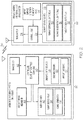
- FIG. 2 provides a block diagram of an augmented autobrake system 20 deployed onboard an aircraft, as illustrated in accordance with an exemplary embodiment of the present invention.
- FIG. 2 also provides a block diagram of an RWSL system 22, which can be utilized in conjunction with RWSL system 22 and which is similar RWSL system 12 shown in FIG. 1 .
- RWSL system 22 is similar to RWSL system 12 ( FIG. 1 ) in the sense that system 22 includes the following components: (i) control logic 24, (ii) ASDE 26, which provides control logic 24 with data regarding ground traffic and runway occupancy, and (iii) runway status lights 28, which are selectively illuminated by control logic 24 to provide visual indications of runway status in the above-described manner.
- control logic 24 controls the following components:
- ASDE 26 which provides control logic 24 with data regarding ground traffic and runway occupancy
- runway status lights 28 which are selectively illuminated by control logic 24 to provide visual indications of runway status in the above-described manner.
- runway status lights 28 include RELs 30, RILs 31, and THLs 32.
- RWSL system 22 further includes a transmitter 34, which is utilized by control logic 24 to wirelessly transmit runway status data to a wireless receiver included within augmented autobrake system 20 (indicated in FIG. 2 by symbol 36 ).
- the "runway status data" can include any information from which autobrake system 20 can identify runway incursion zones, as described more fully below. For example, such information can include data regarding the present location and movement of other aircraft and ground vehicles across an airport surface, such as surface 14 shown in FIG. 1 . Additionally or alternatively, such information can include a relatively simple indication of which, if any, runway status lights 28 are currently illuminated. This data may be transmitted from RWSL system 22 via transmitter 34 at a predetermined refresh rate of, for example, 0.1 second intervals to provide autobrake system 20 with updated traffic / runway status information ona near "real-time" basis.
- Augmented autobrake system 20 includes the following components, each of which may be comprised of multiple devices, systems, or elements: (i) a controller 40; (ii) a wireless receiver 42 coupled to an input of controller 40, (iii) a number of onboard data sources 44 coupled to one or more inputs of controller 40, (iv) one or more alert devices 46 coupled to one or more outputs of controller 40, and (v) an aircraft brake mechanism 48 coupled to an output of controller 40.
- receiver 42 is preferably implemented as a transceiver and is thus referred to as "transceiver 42" hereafter.
- the lines connecting the components of augmented autobrake system 20 denote operative connections, which can be implemented as hardwire or wireless connections utilizing known aircraft infrastructure connections.
- augmented autobrake system 20 and the ownship A/C will typically include various other devices and components for providing additional functions and features, which are not shown in FIG. 2 and will not be described herein to avoid unnecessarily obscuring the invention.
- augmented autobrake system 20 is schematically illustrated as a single unit in FIG. 2 , the individual elements and components of augmented autobrake system 20 can be implemented in a distributed manner using any number of physically-distinct and operatively-interconnected pieces of hardware or equipment.
- Controller 40 itself can be implemented utilizing any suitable number of individual microprocessors, navigational equipment, memories, power supplies, storage devices, interface cards, and other standard components known in the art.
- the controller 40 may include or cooperate with any number of software programs (e.g., autobrake control programs) or instructions designed to carry out the various methods, process tasks, calculations, and control functions described below.
- controller 40 obtains and processes current data indicative of the runway incursion zones and determines when aircraft brake mechanism 48 should be selectively actuated.
- controller 40 may assume the form of or be a part of a Flight Controls (FC) computer in at least some embodiments.
- FC Flight Controls
- Wireless transceiver 42 can assume any form suitable for receiving wireless signals containing runway status data from transmitter 34 of RWSL system 22 and will often be included in a larger communication or data link module.
- aircraft brake mechanism 48 can assume the form of any device that can be actuated by augmented autobrake system 20 to slow or stop the ownship A/C. In one embodiment, aircraft brake mechanism 48 is a wheel-based hydraulic brake system.
- onboard data sources 44 include one or more onboard sensors 50 and an airport database 52.
- onboard sensors 50 provide controller 40 with data describing the current location, heading, and groundspeed of the ownship A/C (referred to herein as "vector data").
- vehicle data data describing the current location, heading, and groundspeed of the ownship A/C
- onboard sensors 50 may further provide controller 40 with other data, as well, such as information describing the weather and surface conditions of the runway surfaces.
- onboard sensors 50 may be realized using line replaceable units (“LRUs”), transducers, accelerometers, instruments, sensors, and other well-known devices.
- LRUs line replaceable units
- Onboard sensors 50 can also be contained within other systems, which, for the intent of this document, may be considered to be partially or wholly included inaugmented autobrake system 20.
- Such systems may include, but are not limited to, a Flight Management System ("FMS"), an Inertial Reference System (“IRS”), and/or an Attitude Heading Reference System (“AHRS”).
- FMS Flight Management System
- IRS Inertial Reference System
- AHRS Attitude Heading Reference System
- RAAS system such as a SMARTRUNWAY® system, deployed onboard the ownship A/C in certain embodiments, in which case sensors 50 may be included in the RAAS system or provide data thereto.
- Airport database 52 is stored in a memory (not shown) and can include any store of information containing data describing the layout of airport surfaces, such as the runway locations and lengths (referred to herein generally as an "airport surface map").
- the airport database is included within a larger navigation database, such as an Enhanced Ground Proximity Warning System (“EGPWS”) runway database.
- GEPWS Enhanced Ground Proximity Warning System
- Augmented autobrake system 20 further includes alert devices 46 in the form of a flight deck display (FDD) 54 and a sound generator 56.
- FDD 54 can be any image-generating device that operates in the cockpit of an aircraft and which is capable of providing the visual alerts described below.
- FDD 54 may be a stationary device affixed to the cockpit or, instead, a portable device carried into the aircraft cockpit, such as an Electronic Flight Bag (EFB).
- EFB Electronic Flight Bag
- a non-exhaustive list of display devices suitable for use as FDD 54 includes cathode ray tube, liquid crystal, active matrix, and plasma display devices.
- FDD 54 is a multifunction display (MFD).
- sound generator 56 can be any device capable of generating or annunciating the aural alerts described below.
- augmented autobrake system 20 may only include one of FDD 54 and sound generator 56, may include a different type of alert device (e.g., a haptic device), or may not include any alert devices.
- FIG. 3 is a flowchart illustrating an exemplary master process 60 that may be performed by controller 40 of augmented autobrake system 20 ( FIG. 2 ) to determine when selective engagement of aircraft brake mechanism 48 ( FIG. 2 ) is warranted to prevent or at least deter entry of the ownship A/C into arunway incursion zone.
- exemplary process 60 commences with recalling an airport layout or surface map from airport database 52 ( FIG. 2 )for the airport at which the ownship A/C is presently located (STEP 62, FIG. 3 ). Further, at STEP 64 ( FIG. 3 ), controller 40 determines the vector data of the ownship A/C, including position, heading, and ground speed.
- controller 40 obtains runway status data from RWSL system 22 (STEP 66, FIG. 3 ).
- the runway status data can be relatively comprehensive information describing vector data for all air traffic operating on the runway surface, along with runway and taxiway occupancy. Additionally or alternatively, the runway status data can be a relatively simple indication of which, if any, runway status lights are currently illuminated. Utilizing this information, controller 40 is able to determine whether the A/C risks entry into a runway incursion zone (STEP 68, FIG. 3 ).
- controller 40 may utilize the data gathered at STEPS 62, 64, and 66 to project the A/C position at a predefined future point and determine whether the future A/C position will coincide with any runway incursion zones or areas in which a collision could potentially occur with another A/C or ground vehicle.
- controller 40 may identify one or more types of runway incursion zones, such as the predicted incursion of the ownship A/C onto an active runway when taxying, as described more fully below in conjunction with FIG. 4 ; or when the ownship A/C is in the process of takeoff from a runway subject to an incursion (e.g., due to occupancy by another A/C, a ground vehicle, or other object), as described more fully below in conjunction with FIG. 5 .
- controller 40 determines that the A/C risks entry into a potential conflict situation
- controller 40 advances to STEP 70 and commands aircraft brake mechanism 48 to stop or slow the A/C prior to entry into the runway incursion zone.
- augmented autobrake system 20 may effectively prevent the ownship A/C from crossing any RELs in the path of the A/C while the RELs remain illuminated.
- controller 40 may generate an alert during automatic application of brake mechanism 48. This alert bea visual alert generated on FDD 54 ( FIG.
- controller 40 may return to STEP 62 and master process 60 may repeat.
- controller 40 may also generate an aural or visual alert prior to application of aircraft brake mechanism 48 when determining that the A/C is approaching a runway incursion zone.
- an aural warning can be annunciated utilizing sound generator 56 ( FIG. 2 ) stating "UNSAFE CONDITION AHEAD; AUTOBRAKE WILL SOON ENGAGE.”
- controller 40 may progress to STEP 72.
- controller 40 may release aircraft brake mechanism 48 if previously automatically engaged; it being noted that the autobrake system can also typically be manually overridden by application of the brake pedals. Additionally, controller 40 may also generate a message visually conveying or audibility conveying that the autobrake has been released. Furthermore, it is preferred that the alert further advises the aircrew that ATC clearance is still required before the A/C may proceed to cross or takeoff from a runway.
- controller 40 may drive sound generator 56 to generate the following aural message during STEP 72 of master process 60 ( FIG. 3 ): "AUTOBRAKE RELEASED; ATC CLEARANCE REQUIRED BEFORE PROCEEDING.” Controller 40 may then return to STEP 64, and master process 60 may repeat.
- controller 40 can check for multiple different types of runway incursion zones during STEP 68 of exemplary process60 ( FIG. 3 ).
- one runway incursion zone that may be evaluated by controller 40 is the possibility of a runway incursion by the ownship A/C onto a runway occupied by another aircraft.
- FIG. 4 illustrates an exemplary sub-process 74 that can be performed by controller 40 during STEP 68 ( FIG. 3 ) to determine whether such a runway incursion zone exists ahead of the ownship A/C (referred to herein as a "Type 1 Runway Conflict").
- controller 40 first determines whether the ownship A/C is approaching a runway utilizing the data gathered during STEPS 62 and 64 of master process 60 ( FIG.
- controller 40 If determining that the ownship A/C is not approaching a runway, controller 40 concludes that a Type 1 Runway Conflict does not exist (STEP 78, FIG. 4 ). Controller 40 then advances to STEP 72 of master process 60 ( FIG. 3 ) providing that no other runway incursion zones exist.
- controller 40 determines whether the ownship A/C is approaching a runway. Controller 40 next establishes whether the approaching runway is occupied (STEP 80, FIG. 3 ). Controller 40 determines whether the approaching runway is occupied based, at least in part, on the data obtained from RWSL system 22 ( FIG. 2 ) during STEP 66 of master process 60 ( FIG. 3 ). If the approaching runway is not occupied, controller 40 determines once again that a Type 1 Runway Conflict does not exist (STEP 78 ) and advances to STEP 72 of master process 60 ( FIG. 3 ).
- controller 40 next calculates a threshold stopping distance between the ownship A/C and the approaching runway (STEP 82 ).
- the threshold stopping distance is the distance at which controller 40 first engages aircraft brake mechanism 48 ( FIG. 2 ) to bring the A/C to a complete stop at a designated full stop point, which may be the edge of the approaching runway or, more preferably, a hold line or stop bar located on the intersecting taxiway on which the A/C is presently traveling.
- Controller 40 calculates the threshold stopping distance based upon a number of factors including the ground speed of the A/C and the location of the full stop point (e.g., taxiway hold line) with respect to the current A/C position. In preferred embodiments, controller 40 also considers the airport surface conditions, such as whether ice or water is present on the taxiway, when calculating the threshold stopping distance.
- controller 40 determines whether the current distance between the ownship A/C and the full stop point is greater than the threshold stopping distance calculated during STEP 82 of exemplary sub-process 74 ( FIG. 4 ). If the present distance between the A/C and the full stop point exceeds the threshold stopping distance, application of aircraft brake mechanism 48 ( FIG. 2 ) is not yet warranted and controller 40 returns to STEP 80. Controller 40 will thus continually cycle through STEPS 80, 82, and 84 until such time as the approaching runway is no longer occupied (in which case, the query presented at STEP 80 is answered in the negative) or until such time as the distance separating the A/C and the full stop point is equal to or slightly less than the threshold stopping distance.
- the threshold stopping distance can be adjusted, as appropriate, to reflect dynamically-changing conditions, such runway surface conditions.
- controller 40 concludes that a Runway Conflict Type 1 is impending (STEP 86, FIG. 4 ) and advances to STEP 70 of master process 60 ( FIG. 3 ).
- controller 40 commands aircraft brake mechanism 48 to provide a smooth or gradual stop over the calculated braking distance and an alert may be generated.
- controller 40 then returns to STEP 62 and repeat master process 60. In this manner, controller 40 and, more generally, autobrake system 20 automatically slows or stops the A/C prior to entry into an occupied runway thereby reducing the likelihood of runway incursions.
- controller 40 may also check for other types of runway incursion zones during STEP 68 of master process 60 ( FIG. 3 ). For example, controller 40 can check for a runway conflict of occurring when the ownship A/C is about to or pending takeoff from a runway occupied by another A/C, a ground vehicle, or other object.
- FIG. 5 illustrates a second exemplary sub-process 90 that can be performed by controller 40 during STEP 68 ( FIG. 3 ) to determine whether the ownship A/C is pending takeoff from a designated runway that is occupied by another vehicle or that is subject to an imminent runway incursion (referred to herein as a "Runway Conflict Type 2").
- Sub-process 90 FIG. 5
- Sub-process 90 can be performed in parallel with sub-process 74 ( FIG.
- sub-process 90 may begin by first determining whether the ownship A/C is pending takeoff from a designated runway (STEP 92 ); that is, whether the A/C is ready and awaiting takeoff from the designated runway.This may be determined based upon the data obtained during STEPS 62 and 64 of master process 60 ( FIG. 3 ), possibly along with data received from the cockpit indicating that the aircrew is readying the A/C for takeoff. If it is determined that the A/C is not pending takeoff, controller 40 ( FIG.
- controller 40 concludes that a Runway Conflict Type 2 does not exist (STEP 94 ). Providing that no other runway incursion zones exist, controller 40 then advances to STEP 72 of master process 60 ( FIG. 3 ) and releases the autobrake if engaged, as previously described.
- controller 40 advances to STEP 96 of sub-process 92 ( FIG. 5 ). At this step, controller 40 determines whether the designated runway is occupied or an imminent incursion into the runway is predicted. Controller 40 can make this determination based upon the data received during STEPS 62 and 66 of master process 60 ( FIG. 3 ). With respect to whether a runway incursion is imminent, this can be determined based upon the vector data (current position, heading, and ground speed) of other A/C and ground vehicles relative to the designated runway.
- controller 40 If it is determined that the designated runway is not occupied and an incursion into the runway is not imminent, controller 40 again concludes that a Runway Conflict Type 2 does not exist (STEP 94 ). Providing that no other runway incursion zones exist, controller 40 then advances to STEP 72 of master process 60 ( FIG. 3 ). Alternatively, if determining that the designated runway is occupied or an incursion into the runway is imminent, controller 40 concludes a Runway Conflict Type 2 exists (STEP 98 ). Accordingly, controller 40 advances to STEP
- autobrake system 20 prevents A/C takeoff until the designated runway is no longer occupied by another A/C or ground vehicle or otherwise subject to a runway incursion.
- Corresponding visual and/or aural alerts may also be generated, as previously described, in conjunction with engagement of the autobrake.
- augmented autobrake system 20 may prevent the ownship A/C from crossing any THLs in the path of the A/C while the THLs remain illuminated. In this manner, augmented autobrake system 20 decreases the likelihood of the ownship A/C colliding with another A/C, ground vehicle, or other object during takeoff in the unlikely event of a runway incursion.
- controller 40 of augmented autobrake system 20 can also determine whether entry of the ownship A/C into a runway incursion zone is unavoidable despite automatic application of the aircraft brakes and, if so, transmit a corresponding alert to ATC and/or to any aircraft in the vicinity of the ownship A/C. More specifically, controller 40 may utilize the data gathered during STEPS 62, 64, and 66 of process 60 ( FIG.3 ) to determine whether a full stop of the ownship A/C is possible prior to incursion of the ownship A/C onto an occupied runway.
- controller 40 may cause transceiver 42 to send a Notice to Airmen (NOTAM) message to neighboring aircraft indicating that an incursion or intrusion onto a particular runway by the ownship A/C is imminent.
- NOTAM Notice to Airmen
- the NOTAM message may identify the runway pending incursion and, perhaps, provide the identity of the ownship A/C.
- augmented autobrake system 20 FIG. 2
- Such additional steps can be performed, for example, following STEP 84 of sub-process 74 ( FIG. 4 ).
- augmented autobrake system 20 may also generate in-flight alerts in instances wherein it is determined that a runway at which the ownship A/C is scheduled to land in the near future is subject to or at risk of a runway incursion.
- a runway at which the ownship A/C is scheduled to land in the near future is subject to or at risk of a runway incursion.
- data from RWSL system 22 FIG. 2
- controller 40 of augmented autobrake system 20 FIG.
- Augmented autobrake system 20 ( FIG. 2 ) can generate one or more alerts within the cockpit of the ownship A/C (e.g., a visual alert generated on FDD 54 and/or an aural alert generated via sound generator 56 ) notifying the aircrew of the potential incursion.
- augmented autobrake system 20 ( FIG. 2 ) may also send an alert message to ATC via transceiver 42 describing the potential incursion. The pilot of the ownship A/C and the ATC can then determined whether a detour or hold is appropriate.
- Augmented autobrake system 20 ( FIG. 2 ) may also generate in-flight alerts in other instances, as well.
- Augmented autobrake system 20 may receive data from RWSL system 22 (sent via transmitter 34 ) indicating the illumination status of the RILs 31 and RELs 30 bordering the runway at which the ownship A/C is scheduled to land.
- controller 40 of augmented autobrake system 20 can again generate one or more alerts within the cockpit of the ownship A/C (e.g., a visual alert and/or aural alert) notifying the aircrew of the increased risk of incursion onto the runway.
- Augmented autobrake system 20 may also send an alert message to ATC via transceiver 42 describing the potential incursion. Once again, the decision whether to detour, hold, or proceed with the scheduled landing can be left to the ATC and pilot of the ownship A/C.
- embodiments of an augmented or enhanced autobrake system to reduces the likelihood of runway incursions and other runway conflicts.
- embodiments of the augmented autobrake system can leverage existing systems onboard an aircraft (e.g., conventional autobrake systems and runway advisory and awareness systems, such as the SMARTRUNWAY® system developed by the present assignee) to provide the unique functionality described above, while requiring little to no hardware modifications to an aircraft.
- runway safety and advisory systems currently deployed onboard aircraft may be augmented with RWSL data to effectively auto-control the aircraft brakes to avoid potential runway incursions.
- the augmented autobrake system identifies different types of runway incursion zones based upon runway status data obtained from an RWSL and onboard data sources, and controls the autobrake mechanism to prevent entry of the ownship A/C into the runway incursion zones.
- embodiments of the autobrake system can control the autobrake mechanism to prevent the A/C from crossing any currently-illuminated runway status lights. While the foregoing exemplary embodiment was described above in the context of a fully functioning computer system (i.e., augmented autobrake system 20 shown in FIG.
Landscapes
- Engineering & Computer Science (AREA)
- Aviation & Aerospace Engineering (AREA)
- Physics & Mathematics (AREA)
- General Physics & Mathematics (AREA)
- Transportation (AREA)
- Mechanical Engineering (AREA)
- Chemical & Material Sciences (AREA)
- Combustion & Propulsion (AREA)
- Traffic Control Systems (AREA)
- Radar, Positioning & Navigation (AREA)
- Remote Sensing (AREA)
Claims (9)
- Système de freinage automatique augmenté (20) déployé à bord d'un aéronef, le système de freinage automatique augmenté comprenant :un récepteur sans fil (42) configuré pour recevoir des données de situation de piste ;un mécanisme de freinage (48) d'aéronef ; etun contrôleur (40) couplé au récepteur sans fil et au mécanisme de freinage d'aéronef, le contrôleur étant configuré pour : (i) identifier (68) lorsque l'aéronef est censé pénétrer dans une zone d'incursion sur piste sur la base au moins en partie des données de situation de piste et de données de vecteur relatives à l'aéronef, et (ii) lorsque l'aéronef est censé pénétrer dans une zone d'incursion sur piste, commander (70) au mécanisme de freinage d'aéronef d'immobiliser l'aéronef avant que celui-ci ne pénètre dans la zone d'incursion sur piste ;les données de situation de piste étant reçues depuis un système de feux d'avertissement et de situation de piste (RWSL) (22) et décrivant, le cas échéant, quels feux de situation de piste (28) du système RWSL sont actuellement allumés ; etle contrôleur étant configuré en outre pour déclencher sélectivement le mécanisme de freinage d'aéronef pour empêcher l'aéronef de franchir tout feu de situation de piste actuellement allumé du système RWSL.
- Système de freinage automatique augmenté (20) selon la revendication 1, comprenant en outre des sources de données embarquées (44) couplées au contrôleur (40), le contrôleur étant configuré en outre pour identifier lorsque l'aéronef est censé pénétrer dans une zone d'incursion sur piste sur la base au moins en partie de données fournies par les sources de données embarquées décrivant la position, le cap et la vitesse sol de l'aéronef sur une surface (14) d'aéroport.
- Système de freinage automatique augmenté (20) selon la revendication 2, comprenant en outre une base de données d'aéroports (52) couplée au contrôleur (40), et dans lequel le contrôleur est configuré pour déterminer lorsque l'aéronef est censé pénétrer dans une zone d'incursion sur piste :en établissant (76) si l'aéronef s'approche ou non d'une piste sur la base au moins en partie d'un plan de surface d'aéroport extrait de la base de données d'aéroports ; ets'il établit que l'aéronef s'approche d'une piste, en déterminant (80) si la piste est actuellement occupée ou non.
- Système de freinage automatique augmenté (20) selon la revendication 3, dans lequel, après avoir déterminé que la piste approchée est occupée, le contrôleur (40) est configuré en outre pour :déterminer (82) une distance d'immobilisation seuil jusqu'à une ligne d'attente de voie de circulation adjacente à la piste approchée sur la base, au moins en partie, de la vitesse sol de l'aéronef ; etsi la piste approchée reste occupée lorsque la distance entre l'aéronef et la ligne d'attente de voie de circulation est inférieure ou égale à la distance d'immobilisation seuil, déclencher (86) le mécanisme de freinage (48) d'aéronef pour amener l'aéronef à une immobilisation progressive au niveau de la ligne d'attente de voie de circulation.
- Système de freinage automatique augmenté (20) selon la revendication 1, dans lequel le contrôleur (40) est configuré pour :déterminer (92) si l'aéronef est en attente de décollage ou non d'une piste ;si l'aéronef est en attente de décollage d'une piste, déterminer (96) si la piste est occupée ou non ; etcommander (98) au mécanisme de freinage (48) d'aéronef d'empêcher le décollage de l'aéronef jusqu'à ce que la piste ne soit plus occupée.
- Système de freinage automatique augmenté (20) selon la revendication 1, comprenant en outre un dispositif d'alerte (46), et dans lequel le contrôleur (40) est configuré en outre pour :déterminer si une piste sur laquelle il est prévu que l'aéronef atterrisse fait l'objet ou non d'une incursion sur piste sur la base, au moins en partie, des données de situation de piste reçues depuis le système RWSL (22) ; ets'il détermine que la piste sur laquelle il est prévu que l'aéronef atterrisse fait l'objet d'une incursion sur piste, générer une alerte (86) au moyen du dispositif d'alerte.
- Procédé (60) mis en oeuvre par un contrôleur (40) d'un système de freinage automatique augmenté (20) déployé à bord d'un aéronef, le procédé comprenant :au niveau du contrôleur, la détermination (68) si l'aéronef risque ou non de pénétrer dans une zone d'incursion sur piste sur la base au moins en partie de données de situation de piste et de données de vecteur relatives à l'aéronef ; eten cas de détermination que l'aéronef risque de pénétrer dans une zone d'incursion sur piste, l'émission d'une commande (70) du contrôleur (40) à un mécanisme de freinage (48) d'aéronef en vue de ralentir ou d'immobiliser l'aéronef avant que celui-ci ne pénètre dans la zone d'incursion sur piste ;les données de situation de piste étant reçues depuis un système de feux d'avertissement et de situation de piste (RWSL) (22) et décrivant, le cas échéant, quels feux de situation de piste (28) du système RWSL sont actuellement allumés ; etle procédé comprenant en outre le déclenchement sélectif du mécanisme de freinage d'aéronef pour empêcher l'aéronef de franchir tout feu de situation de piste actuellement allumé du système RWSL.
- Procédé (60) selon la revendication 7, dans lequel la détermination (68) si l'aéronef risque ou non de pénétrer dans une zone d'incursion sur piste comprend la détermination (84) si l'aéronef est censé ou non faire intrusion sur une piste occupée sur la base au moins en partie de données de situation de piste reçues depuis le système RWSL (22), des données de vecteur et d'un plan de surface d'aéroport extrait d'une base de données d'aéroports (52).
- Procédé (60) selon la revendication 7, dans lequel la détermination (68) si l'aéronef risque ou non de pénétrer dans une zone d'incursion sur piste comprend la détermination (96) si l'aéronef est en attente de décollage ou non d'une piste qui est actuellement occupée.
Applications Claiming Priority (1)
| Application Number | Priority Date | Filing Date | Title |
|---|---|---|---|
| US14/636,354 US9472111B2 (en) | 2015-03-03 | 2015-03-03 | Augmented aircraft autobrake systems for preventing runway incursions, related program products, and related processes |
Publications (2)
| Publication Number | Publication Date |
|---|---|
| EP3064407A1 EP3064407A1 (fr) | 2016-09-07 |
| EP3064407B1 true EP3064407B1 (fr) | 2019-07-10 |
Family
ID=55404604
Family Applications (1)
| Application Number | Title | Priority Date | Filing Date |
|---|---|---|---|
| EP16156216.0A Active EP3064407B1 (fr) | 2015-03-03 | 2016-02-17 | Systèmes de freinage automatique d'aéronef augmentés pour empêcher des incursions de pistes et procédés associés |
Country Status (3)
| Country | Link |
|---|---|
| US (1) | US9472111B2 (fr) |
| EP (1) | EP3064407B1 (fr) |
| CN (1) | CN105938661B (fr) |
Families Citing this family (12)
| Publication number | Priority date | Publication date | Assignee | Title |
|---|---|---|---|---|
| US10216186B2 (en) * | 2016-05-23 | 2019-02-26 | Sikorsky Aircraft Corporation | Task allocation and variable autonomy levels |
| US10810892B2 (en) * | 2017-02-01 | 2020-10-20 | Honeywell International Inc. | Air traffic control flight management |
| US10699587B2 (en) * | 2017-06-26 | 2020-06-30 | Honeywell International Inc. | Aircraft taxiway routing |
| GB2576617B (en) * | 2018-07-03 | 2021-06-23 | Borealis Tech Ltd | Intelligent airport ramp and electric taxi-driven aircraft ground movement monitoring system |
| CN109817026B (zh) * | 2019-02-14 | 2021-01-12 | 中国民用航空总局第二研究所 | 一种跑道进入灯的控制方法、装置、设备及介质 |
| US12267755B2 (en) * | 2019-07-10 | 2025-04-01 | Smartsky Networks LLC | Remote airport management services |
| US10867522B1 (en) * | 2019-08-28 | 2020-12-15 | Honeywell International Inc. | Systems and methods for vehicle pushback collision notification and avoidance |
| CN111613095B (zh) * | 2020-05-19 | 2022-08-16 | 上海交通大学 | 面向商用飞机远程驾驶系统的起飞前场面运行控制方法 |
| CN112330145B (zh) * | 2020-11-04 | 2023-07-21 | 中国人民大学 | 一种降低航班道口冲突率的机位分配方法和系统 |
| US20240363012A1 (en) * | 2023-04-25 | 2024-10-31 | Purdue Research Foundation | Systems and methods for aviation runway incursion avoidance |
| US20250006064A1 (en) * | 2023-06-27 | 2025-01-02 | The Boeing Company | Methods and systems for preventing wrong surface events |
| EP4657410A1 (fr) * | 2024-05-20 | 2025-12-03 | Airbus SAS | Equipement de surveillance d'aeronef et procede de protection contre les incursions |
Family Cites Families (14)
| Publication number | Priority date | Publication date | Assignee | Title |
|---|---|---|---|---|
| US5374932A (en) * | 1993-08-02 | 1994-12-20 | Massachusetts Institute Of Technology | Airport surface surveillance system |
| FR2884953B1 (fr) * | 2005-04-22 | 2007-07-06 | Thales Sa | Procede et dispositif embarque, pour aeronef, d'alerte d'incursion de piste |
| US7765037B2 (en) * | 2005-08-19 | 2010-07-27 | Rockwell Collins, Inc. | Runway incursion detection system and method for displaying a runway incursion |
| US7818100B2 (en) | 2007-04-03 | 2010-10-19 | The Boeing Company | System and method for optimized runway exiting |
| US8285473B1 (en) * | 2009-07-09 | 2012-10-09 | The Boeing Company | Predictive relevant traffic determination using vehicle states descriptions |
| US8638240B2 (en) * | 2011-02-07 | 2014-01-28 | Honeywell International Inc. | Airport taxiway collision alerting system |
| US8620493B2 (en) | 2012-05-03 | 2013-12-31 | Honeywell International Inc. | Electric taxi auto-guidance and control system |
| US20130321169A1 (en) | 2012-05-30 | 2013-12-05 | Honeywell International Inc. | Airport surface collision-avoidance system (ascas) |
| US9959774B2 (en) | 2012-05-30 | 2018-05-01 | Honeywell International Inc. | Systems and methods for displaying obstacle-avoidance information during surface operations |
| CN103325193A (zh) * | 2012-12-13 | 2013-09-25 | 南京航空航天大学 | 基于无线传感器网络的机场跑道入侵防御系统及方法 |
| WO2014115139A1 (fr) * | 2013-01-23 | 2014-07-31 | Iatas (Automatic Air Traffic Control) Ltd | Système et procédés pour services de contrôle de trafic aérien d'aéroport automatisés |
| US8965671B2 (en) | 2013-03-16 | 2015-02-24 | Honeywell International Inc. | Aircraft taxiing system |
| US9139307B2 (en) * | 2013-06-28 | 2015-09-22 | Honeywell International Inc. | Aircraft systems and methods for displaying runway lighting information |
| CN103413466A (zh) * | 2013-07-08 | 2013-11-27 | 中国航空无线电电子研究所 | 机载可视化地面引导和告警装置及其引导和告警方法 |
-
2015
- 2015-03-03 US US14/636,354 patent/US9472111B2/en active Active
-
2016
- 2016-02-17 EP EP16156216.0A patent/EP3064407B1/fr active Active
- 2016-03-02 CN CN201610117023.XA patent/CN105938661B/zh active Active
Non-Patent Citations (1)
| Title |
|---|
| None * |
Also Published As
| Publication number | Publication date |
|---|---|
| US20160260335A1 (en) | 2016-09-08 |
| EP3064407A1 (fr) | 2016-09-07 |
| US9472111B2 (en) | 2016-10-18 |
| CN105938661A (zh) | 2016-09-14 |
| CN105938661B (zh) | 2022-03-11 |
Similar Documents
| Publication | Publication Date | Title |
|---|---|---|
| EP3064407B1 (fr) | Systèmes de freinage automatique d'aéronef augmentés pour empêcher des incursions de pistes et procédés associés | |
| US7796055B2 (en) | Runway status indication and traffic information display and filtering | |
| EP3474259B1 (fr) | Procédé et système de concaténation contextuelle d'alertes d'affichage, sonores et vocales | |
| US20200273357A1 (en) | Advisor system and method | |
| US8965671B2 (en) | Aircraft taxiing system | |
| EP2669706B1 (fr) | Systèmes et procédés pour afficher des informations à évitement d'obstacles lors d'opérations de surface | |
| Schönefeld et al. | Runway incursion prevention systems: A review of runway incursion avoidance and alerting system approaches | |
| US9074891B2 (en) | High integrity, surface guidance system for aircraft electric taxi | |
| US12518641B2 (en) | Systems and methods for generating avionic displays indicating wake turbulence | |
| US20180061243A1 (en) | System and methods for automated airport air traffic control services | |
| RU2560220C1 (ru) | Способ и устройство для управления наземным движением мобильных объектов на аэродроме | |
| EP3444791A2 (fr) | Système et procédés de services automatisés de contrôle du trafic aérien d'aéroports | |
| CN108460995A (zh) | 用于防止跑道侵入的显示系统和方法 | |
| CN108766036A (zh) | 机载滑行道和跑道可视化引导及告警装置 | |
| US20020116127A1 (en) | Airplane ground location methods and systems and airplanes | |
| CN112908043A (zh) | 使用载具灯进行碰撞感知 | |
| US6571167B2 (en) | Airport takeoff window | |
| US20130345906A1 (en) | Methods and systems for taxiway traffic alerting | |
| Young | Understanding Crew Decision-Making in the Presence of Complexity-A Flight Simulation Experiment | |
| US20240363012A1 (en) | Systems and methods for aviation runway incursion avoidance | |
| EP4462407A1 (fr) | Systèmes et procédés de génération d'affichages avioniques indiquant une turbulence de sillage | |
| EP4589571A1 (fr) | Systèmes et procédés de génération de directives d'évitement de collision | |
| Ding | Analysis and simulation of advanced ground motion guidance and control system | |
| Ludwig | Direct alerting to the cockpit for runway incursions | |
| McLean et al. | Runway incursions and prevention systems |
Legal Events
| Date | Code | Title | Description |
|---|---|---|---|
| PUAI | Public reference made under article 153(3) epc to a published international application that has entered the european phase |
Free format text: ORIGINAL CODE: 0009012 |
|
| 17P | Request for examination filed |
Effective date: 20160217 |
|
| AK | Designated contracting states |
Kind code of ref document: A1 Designated state(s): AL AT BE BG CH CY CZ DE DK EE ES FI FR GB GR HR HU IE IS IT LI LT LU LV MC MK MT NL NO PL PT RO RS SE SI SK SM TR |
|
| AX | Request for extension of the european patent |
Extension state: BA ME |
|
| GRAJ | Information related to disapproval of communication of intention to grant by the applicant or resumption of examination proceedings by the epo deleted |
Free format text: ORIGINAL CODE: EPIDOSDIGR1 |
|
| STAA | Information on the status of an ep patent application or granted ep patent |
Free format text: STATUS: GRANT OF PATENT IS INTENDED |
|
| GRAP | Despatch of communication of intention to grant a patent |
Free format text: ORIGINAL CODE: EPIDOSNIGR1 |
|
| RIC1 | Information provided on ipc code assigned before grant |
Ipc: B60T 8/17 20060101AFI20190121BHEP Ipc: G08G 5/06 20060101ALI20190121BHEP |
|
| INTG | Intention to grant announced |
Effective date: 20190221 |
|
| GRAS | Grant fee paid |
Free format text: ORIGINAL CODE: EPIDOSNIGR3 |
|
| GRAA | (expected) grant |
Free format text: ORIGINAL CODE: 0009210 |
|
| STAA | Information on the status of an ep patent application or granted ep patent |
Free format text: STATUS: THE PATENT HAS BEEN GRANTED |
|
| AK | Designated contracting states |
Kind code of ref document: B1 Designated state(s): AL AT BE BG CH CY CZ DE DK EE ES FI FR GB GR HR HU IE IS IT LI LT LU LV MC MK MT NL NO PL PT RO RS SE SI SK SM TR |
|
| REG | Reference to a national code |
Ref country code: GB Ref legal event code: FG4D |
|
| REG | Reference to a national code |
Ref country code: CH Ref legal event code: EP Ref country code: AT Ref legal event code: REF Ref document number: 1153244 Country of ref document: AT Kind code of ref document: T Effective date: 20190715 |
|
| REG | Reference to a national code |
Ref country code: DE Ref legal event code: R096 Ref document number: 602016016510 Country of ref document: DE |
|
| REG | Reference to a national code |
Ref country code: IE Ref legal event code: FG4D |
|
| REG | Reference to a national code |
Ref country code: NL Ref legal event code: MP Effective date: 20190710 |
|
| REG | Reference to a national code |
Ref country code: LT Ref legal event code: MG4D |
|
| REG | Reference to a national code |
Ref country code: AT Ref legal event code: MK05 Ref document number: 1153244 Country of ref document: AT Kind code of ref document: T Effective date: 20190710 |
|
| PG25 | Lapsed in a contracting state [announced via postgrant information from national office to epo] |
Ref country code: SE Free format text: LAPSE BECAUSE OF FAILURE TO SUBMIT A TRANSLATION OF THE DESCRIPTION OR TO PAY THE FEE WITHIN THE PRESCRIBED TIME-LIMIT Effective date: 20190710 Ref country code: AT Free format text: LAPSE BECAUSE OF FAILURE TO SUBMIT A TRANSLATION OF THE DESCRIPTION OR TO PAY THE FEE WITHIN THE PRESCRIBED TIME-LIMIT Effective date: 20190710 Ref country code: FI Free format text: LAPSE BECAUSE OF FAILURE TO SUBMIT A TRANSLATION OF THE DESCRIPTION OR TO PAY THE FEE WITHIN THE PRESCRIBED TIME-LIMIT Effective date: 20190710 Ref country code: NO Free format text: LAPSE BECAUSE OF FAILURE TO SUBMIT A TRANSLATION OF THE DESCRIPTION OR TO PAY THE FEE WITHIN THE PRESCRIBED TIME-LIMIT Effective date: 20191010 Ref country code: LT Free format text: LAPSE BECAUSE OF FAILURE TO SUBMIT A TRANSLATION OF THE DESCRIPTION OR TO PAY THE FEE WITHIN THE PRESCRIBED TIME-LIMIT Effective date: 20190710 Ref country code: PT Free format text: LAPSE BECAUSE OF FAILURE TO SUBMIT A TRANSLATION OF THE DESCRIPTION OR TO PAY THE FEE WITHIN THE PRESCRIBED TIME-LIMIT Effective date: 20191111 Ref country code: BG Free format text: LAPSE BECAUSE OF FAILURE TO SUBMIT A TRANSLATION OF THE DESCRIPTION OR TO PAY THE FEE WITHIN THE PRESCRIBED TIME-LIMIT Effective date: 20191010 Ref country code: NL Free format text: LAPSE BECAUSE OF FAILURE TO SUBMIT A TRANSLATION OF THE DESCRIPTION OR TO PAY THE FEE WITHIN THE PRESCRIBED TIME-LIMIT Effective date: 20190710 Ref country code: HR Free format text: LAPSE BECAUSE OF FAILURE TO SUBMIT A TRANSLATION OF THE DESCRIPTION OR TO PAY THE FEE WITHIN THE PRESCRIBED TIME-LIMIT Effective date: 20190710 |
|
| PG25 | Lapsed in a contracting state [announced via postgrant information from national office to epo] |
Ref country code: LV Free format text: LAPSE BECAUSE OF FAILURE TO SUBMIT A TRANSLATION OF THE DESCRIPTION OR TO PAY THE FEE WITHIN THE PRESCRIBED TIME-LIMIT Effective date: 20190710 Ref country code: GR Free format text: LAPSE BECAUSE OF FAILURE TO SUBMIT A TRANSLATION OF THE DESCRIPTION OR TO PAY THE FEE WITHIN THE PRESCRIBED TIME-LIMIT Effective date: 20191011 Ref country code: AL Free format text: LAPSE BECAUSE OF FAILURE TO SUBMIT A TRANSLATION OF THE DESCRIPTION OR TO PAY THE FEE WITHIN THE PRESCRIBED TIME-LIMIT Effective date: 20190710 Ref country code: RS Free format text: LAPSE BECAUSE OF FAILURE TO SUBMIT A TRANSLATION OF THE DESCRIPTION OR TO PAY THE FEE WITHIN THE PRESCRIBED TIME-LIMIT Effective date: 20190710 Ref country code: IS Free format text: LAPSE BECAUSE OF FAILURE TO SUBMIT A TRANSLATION OF THE DESCRIPTION OR TO PAY THE FEE WITHIN THE PRESCRIBED TIME-LIMIT Effective date: 20191110 Ref country code: ES Free format text: LAPSE BECAUSE OF FAILURE TO SUBMIT A TRANSLATION OF THE DESCRIPTION OR TO PAY THE FEE WITHIN THE PRESCRIBED TIME-LIMIT Effective date: 20190710 |
|
| PG25 | Lapsed in a contracting state [announced via postgrant information from national office to epo] |
Ref country code: TR Free format text: LAPSE BECAUSE OF FAILURE TO SUBMIT A TRANSLATION OF THE DESCRIPTION OR TO PAY THE FEE WITHIN THE PRESCRIBED TIME-LIMIT Effective date: 20190710 |
|
| PG25 | Lapsed in a contracting state [announced via postgrant information from national office to epo] |
Ref country code: RO Free format text: LAPSE BECAUSE OF FAILURE TO SUBMIT A TRANSLATION OF THE DESCRIPTION OR TO PAY THE FEE WITHIN THE PRESCRIBED TIME-LIMIT Effective date: 20190710 Ref country code: IT Free format text: LAPSE BECAUSE OF FAILURE TO SUBMIT A TRANSLATION OF THE DESCRIPTION OR TO PAY THE FEE WITHIN THE PRESCRIBED TIME-LIMIT Effective date: 20190710 Ref country code: DK Free format text: LAPSE BECAUSE OF FAILURE TO SUBMIT A TRANSLATION OF THE DESCRIPTION OR TO PAY THE FEE WITHIN THE PRESCRIBED TIME-LIMIT Effective date: 20190710 Ref country code: PL Free format text: LAPSE BECAUSE OF FAILURE TO SUBMIT A TRANSLATION OF THE DESCRIPTION OR TO PAY THE FEE WITHIN THE PRESCRIBED TIME-LIMIT Effective date: 20190710 Ref country code: EE Free format text: LAPSE BECAUSE OF FAILURE TO SUBMIT A TRANSLATION OF THE DESCRIPTION OR TO PAY THE FEE WITHIN THE PRESCRIBED TIME-LIMIT Effective date: 20190710 |
|
| PG25 | Lapsed in a contracting state [announced via postgrant information from national office to epo] |
Ref country code: CZ Free format text: LAPSE BECAUSE OF FAILURE TO SUBMIT A TRANSLATION OF THE DESCRIPTION OR TO PAY THE FEE WITHIN THE PRESCRIBED TIME-LIMIT Effective date: 20190710 Ref country code: SM Free format text: LAPSE BECAUSE OF FAILURE TO SUBMIT A TRANSLATION OF THE DESCRIPTION OR TO PAY THE FEE WITHIN THE PRESCRIBED TIME-LIMIT Effective date: 20190710 Ref country code: IS Free format text: LAPSE BECAUSE OF FAILURE TO SUBMIT A TRANSLATION OF THE DESCRIPTION OR TO PAY THE FEE WITHIN THE PRESCRIBED TIME-LIMIT Effective date: 20200224 Ref country code: SK Free format text: LAPSE BECAUSE OF FAILURE TO SUBMIT A TRANSLATION OF THE DESCRIPTION OR TO PAY THE FEE WITHIN THE PRESCRIBED TIME-LIMIT Effective date: 20190710 |
|
| REG | Reference to a national code |
Ref country code: DE Ref legal event code: R097 Ref document number: 602016016510 Country of ref document: DE |
|
| PLBE | No opposition filed within time limit |
Free format text: ORIGINAL CODE: 0009261 |
|
| STAA | Information on the status of an ep patent application or granted ep patent |
Free format text: STATUS: NO OPPOSITION FILED WITHIN TIME LIMIT |
|
| PG2D | Information on lapse in contracting state deleted |
Ref country code: IS |
|
| 26N | No opposition filed |
Effective date: 20200603 |
|
| PG25 | Lapsed in a contracting state [announced via postgrant information from national office to epo] |
Ref country code: SI Free format text: LAPSE BECAUSE OF FAILURE TO SUBMIT A TRANSLATION OF THE DESCRIPTION OR TO PAY THE FEE WITHIN THE PRESCRIBED TIME-LIMIT Effective date: 20190710 |
|
| REG | Reference to a national code |
Ref country code: CH Ref legal event code: PL |
|
| REG | Reference to a national code |
Ref country code: BE Ref legal event code: MM Effective date: 20200229 |
|
| PG25 | Lapsed in a contracting state [announced via postgrant information from national office to epo] |
Ref country code: MC Free format text: LAPSE BECAUSE OF FAILURE TO SUBMIT A TRANSLATION OF THE DESCRIPTION OR TO PAY THE FEE WITHIN THE PRESCRIBED TIME-LIMIT Effective date: 20190710 Ref country code: LU Free format text: LAPSE BECAUSE OF NON-PAYMENT OF DUE FEES Effective date: 20200217 |
|
| PG25 | Lapsed in a contracting state [announced via postgrant information from national office to epo] |
Ref country code: CH Free format text: LAPSE BECAUSE OF NON-PAYMENT OF DUE FEES Effective date: 20200229 Ref country code: LI Free format text: LAPSE BECAUSE OF NON-PAYMENT OF DUE FEES Effective date: 20200229 |
|
| PG25 | Lapsed in a contracting state [announced via postgrant information from national office to epo] |
Ref country code: IE Free format text: LAPSE BECAUSE OF NON-PAYMENT OF DUE FEES Effective date: 20200217 Ref country code: FR Free format text: LAPSE BECAUSE OF NON-PAYMENT OF DUE FEES Effective date: 20200229 |
|
| PG25 | Lapsed in a contracting state [announced via postgrant information from national office to epo] |
Ref country code: BE Free format text: LAPSE BECAUSE OF NON-PAYMENT OF DUE FEES Effective date: 20200229 |
|
| PG25 | Lapsed in a contracting state [announced via postgrant information from national office to epo] |
Ref country code: MT Free format text: LAPSE BECAUSE OF FAILURE TO SUBMIT A TRANSLATION OF THE DESCRIPTION OR TO PAY THE FEE WITHIN THE PRESCRIBED TIME-LIMIT Effective date: 20190710 Ref country code: CY Free format text: LAPSE BECAUSE OF FAILURE TO SUBMIT A TRANSLATION OF THE DESCRIPTION OR TO PAY THE FEE WITHIN THE PRESCRIBED TIME-LIMIT Effective date: 20190710 |
|
| PG25 | Lapsed in a contracting state [announced via postgrant information from national office to epo] |
Ref country code: MK Free format text: LAPSE BECAUSE OF FAILURE TO SUBMIT A TRANSLATION OF THE DESCRIPTION OR TO PAY THE FEE WITHIN THE PRESCRIBED TIME-LIMIT Effective date: 20190710 |
|
| P01 | Opt-out of the competence of the unified patent court (upc) registered |
Effective date: 20230526 |
|
| PGFP | Annual fee paid to national office [announced via postgrant information from national office to epo] |
Ref country code: GB Payment date: 20260223 Year of fee payment: 11 |
|
| PGFP | Annual fee paid to national office [announced via postgrant information from national office to epo] |
Ref country code: DE Payment date: 20260220 Year of fee payment: 11 |