EP3064465A1 - Dispositif de flèche d'une grue comportant une voilure, grue et procédé de fonctionnement de la grue - Google Patents
Dispositif de flèche d'une grue comportant une voilure, grue et procédé de fonctionnement de la grue Download PDFInfo
- Publication number
- EP3064465A1 EP3064465A1 EP15157628.7A EP15157628A EP3064465A1 EP 3064465 A1 EP3064465 A1 EP 3064465A1 EP 15157628 A EP15157628 A EP 15157628A EP 3064465 A1 EP3064465 A1 EP 3064465A1
- Authority
- EP
- European Patent Office
- Prior art keywords
- jib
- unit
- sail
- crane
- jib device
- Prior art date
- Legal status (The legal status is an assumption and is not a legal conclusion. Google has not performed a legal analysis and makes no representation as to the accuracy of the status listed.)
- Granted
Links
- 238000000034 method Methods 0.000 title claims description 5
- 239000004753 textile Substances 0.000 claims description 8
- 239000000463 material Substances 0.000 claims description 7
- 239000003562 lightweight material Substances 0.000 claims description 5
- OKTJSMMVPCPJKN-UHFFFAOYSA-N Carbon Chemical compound [C] OKTJSMMVPCPJKN-UHFFFAOYSA-N 0.000 description 3
- 229910052799 carbon Inorganic materials 0.000 description 3
- 239000000835 fiber Substances 0.000 description 3
- 229920002430 Fibre-reinforced plastic Polymers 0.000 description 1
- 150000001875 compounds Chemical class 0.000 description 1
- 230000003247 decreasing effect Effects 0.000 description 1
- 239000011151 fibre-reinforced plastic Substances 0.000 description 1
- 238000012544 monitoring process Methods 0.000 description 1
- 239000004033 plastic Substances 0.000 description 1
- 229920003023 plastic Polymers 0.000 description 1
- 239000000725 suspension Substances 0.000 description 1
Images




Classifications
-
- B—PERFORMING OPERATIONS; TRANSPORTING
- B66—HOISTING; LIFTING; HAULING
- B66C—CRANES; LOAD-ENGAGING ELEMENTS OR DEVICES FOR CRANES, CAPSTANS, WINCHES, OR TACKLES
- B66C23/00—Cranes comprising essentially a beam, boom, or triangular structure acting as a cantilever and mounted for translatory of swinging movements in vertical or horizontal planes or a combination of such movements, e.g. jib-cranes, derricks, tower cranes
- B66C23/62—Constructional features or details
Definitions
- the invention is directed on a jib device for a crane, a crane comprising such jib device and a method for operating such crane.
- WO 2011/101132 A1 discloses a luffing jib tower crane. For safety reasons such tower crane can operate for a maximum wind speed, which is according to current safety requirements 72 km/h. However, different safety requirements may lead to a different maximum wind speed. For higher wind speeds, the crane must be taken out of service. According to WO 2011/101132 A1 , the tower crane is rotated actively in a safe position using a wind-safe-position-control. Such concept is laborious and cost-intensive. In particular, in case of emergency, the active wind-safe-position-control may not work. A danger of collision increases.
- a tower crane with a luffing jib out of service means that the jib is parked up at a specific out of service angle, corresponding to a specific out of service radius. In this condition, the slew brake is released.
- This out of service condition is also called weathemane condition, i.e. wind will force the crane's upper part to turn into the wind direction. Thus, the loads on the crane as well as on the crane's supporting structures are minimized.
- the weathervane must be achieved at a wind speed of 40 km/h.
- a torque on the rotational part of the crane provided by the wind force corresponds to the out of service radius of the jib.
- the resulting torque may not be large enough to guarantee weathervaning, in particular at 40 km/h wind speed.
- a jib device for a crane comprising the features of independent claim 1, a crane comprising the features of independent claim 13 and a method comprising the features of independent claim 14.
- a jib device comprising a sail unit with a surface area which is variably adjustable, guarantees weathervaning even at reduced wind speed.
- weathervaning is guaranteed by the sail unit, as a windage can be enlarged.
- a windage is defined by the size of a surface area which is forced by wind.
- a safe, i.e. reduced, out of service radius for the jib can be maintained.
- Such reduced out of service radius is predefined by site constraints, in particular by a steep arrangement of the jib device for reducing a collision risk.
- the sail unit of the inventive jib device enables sufficient increase of the surface area such that the torque is sufficient for weathervaning, in particular at a reduced wind speed of at least 40 km/h.
- an enlarged windage i.e. a wind attack area, may cause a problem once the upper part of the crane is slewing in a direction against the wind force.
- the sail unit is variably adjustable, such that the surface area of the sail unit is decreased, e.g. once the out of service position is left, i.e. during an operation of the crane.
- the sail unit is operable, in particular retractable, between a so-called out of service, parking, configuration of the jib device, in which the sail unit has a first, i.e. maximum, surface area, and an operative configuration of the jib device, in which the sail unit has a second, i.e. minimum, surface area.
- the second surface area is smaller than the first surface area.
- the jib device is intended for a crane, in particular for a tower crane.
- the jib device is connectable to a base unit, in particular a tower, of said crane. Further, the jib device is rotatable about a longitudinal axis of said base unit.
- Retracting means that the wind sail is retractable in particular in a direction parallel to the longitudinal axis of the jib.
- the sail unit comprises at least one wind sail.
- the sail unit comprises several wind sails. It is possible to individually and/or collectively operate the wind sails.
- the wind sail In the parking configuration, the wind sail is arranged parallel to the luffing plane, i.e. perpendicular to the luffing axis of the jib.
- the wind sail In the operative configuration, the wind sail is oriented parallel to the luffing axis, i.e. perpendicular to the luffing plane.
- a crane with such jib device comprises the advantages of the jib device itself.
- Such crane can be a luffing jib tower crane as generally known from WO 2011/101132 A1 .
- Such crane can also be a saddle jib crane. In particular, it is possible to operate such crane easily with safe conditions.
- a jib device with a supporting unit to which the jib is luffably attached simplifies the handling of the jib device.
- the supporting unit itself is preferably rotatable about the longitudinal axis of the base unit.
- the supporting unit is a rotatable base of the jib device.
- the jib is luffable about a luffing axis, which is preferably horizontally oriented.
- a jib device wherein the jib is a lattice jib, is of stable and light weight design.
- a lattice jib can be foldable, i.e. for a self-erecting crane.
- a jib device wherein the sail unit is arranged, in particular at least partly, inside a lattice frame of the lattice jib, comprises enhanced functionality.
- the arrangement of the sail unit is robust and provided with minimum space requirements.
- the jib as a telescopic jib with closed, hollow profiles.
- the sail unit is attached to the telescopic jib, in particular, at an outer surface of the telescopic jib.
- a jib device wherein the sail unit comprises a wind sail simplifies the variable adjustment of the surface area of the sail unit.
- a jib device wherein the wind sail is made from light weight material, guarantees reduced slewing resistance of the jib device.
- the wind sail comprises more than one light weight material, in particular a compound of more than one light weight materials.
- a light weight material can be for instance a fibre reinforced plastic material, in particular carbon fibre plastic material.
- a jib device wherein the wind sail is made from at least one of the group consisting of a rigid material and a textile enhances variable adjustments of the surface area of the sail unit.
- a textile it could be provided on a coil, wherein the textile is retractable by pulling a free end from the coil.
- the coil can be spring-loaded, such that automatically retracting of the coil is enabled.
- a cover around the coil such that the coil is protected inside the cover.
- the cover comprises a, in particular slid-shaped, opening, through which the free end of the coil is retractable.
- a rigid material it could be stored in a folded arrangement in a space-saving manner and is retractable by unfolding in a planar manner.
- a jib device wherein the sail unit comprises a drive for retracting the wind sail, i.e. for variably adjusting the surface area of the sail unit, simplifies the handling of the sail unit.
- a jib device with an operation unit for adjusting the surface area of said sail unit enables immediate handling of the adjustment of the surface area.
- the operation unit is arranged in an operator's cabin of the crane.
- the operation unit comprises a display unit for monitoring the size of the surface area of the sail unit.
- a jib device with a control unit for controlling the adjustment area of the sail unit enables an automized, in particular by closed loop control, operation of the jib device on the crane.
- a jib device with an emergency back-up unit guarantees a stable and safe condition of the crane even in case of emergency.
- a case of emergency is for instance if the primary energy system of the crane is in fold.
- the back-up unit guarantees opening/closing of the sail unit, i.e. retracting the wind sail.
- the wind sail is retracted, i.e. brought into the parking configuration with maximum surface area.
- the emergency back-up unit can comprise an automatic actuator induced by self-weight.
- the automatic actuator is usually in a locked arrangement.
- the emergency back-up unit provides unlocking of said automatic actuator by self-weight such that for instance a brake of a retracting drive is unlocked and thus the retracting drive enables retracting the wind sail.
- a jib device with a sensor unit comprising at least one sensor element for sensing actual loading conditions of the jib device enables the consideration of a priori unknown loading conditions, i.e. a wind force, a luffing angle, actual size of the surface area of the sail unit.
- a priori unknown loading conditions i.e. a wind force, a luffing angle, actual size of the surface area of the sail unit.
- These data is preferably used as input data for a close-loop control for adjusting the surface area of the sail unit, in particular continuously.
- the loading conditions can be monitored.
- the sail unit is retracted between the parking configuration and the operative configuration, in particular without any configuration in between.
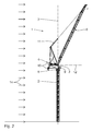
- Fig. 1 shows a side view of a tower crane 1 having a base unit 2 in form of a vertical tower.
- the base unit 2 has a longitudinal axis 3, which is oriented vertically.
- a jib device 4 is provided on an upper end of the base unit 2.
- the jib device 4 is rotatable about the longitudinal axis 3 of the base unit 2. The rotatability is illustrated by an arrow 5.
- the jib device 4 comprises a jib 6.
- the jib 6 is a lattice jib.
- the jib 6 is luffable about a luffing axis 7 attached to a supporting unit 8.
- the luffing axis 7 is oriented horizontally.
- the luffing axis 7 is perpendicular to the drawing plane in Fig. 1 .
- the jib 6 comprises a jib longitudinal axis 13.
- the luffing angle a is defined by the jib longitudinal axis 13 and the horizontal 12.
- the drawing plane in Fig. 1 is oriented parallel to the luffing plane of the jib 6.
- the jib device 4 comprises an operator's cabin 9, counterweight means 10 and suspension means 11. However, such means 9, 10, 11 are already known in the art.
- the tower crane 1 according to Fig. 1 is in a parking configuration.
- the jib 6 is arranged with a luffing angle a regarding the horizontal 12.
- the luffing angle is at least 45°, in particular at least 55°, in particular at least 65°, in particular at least 70° and in particular at least 80° to 85°.
- the jib device 4 comprises a jib radius r, which is defined as the projection of the overall jib length on the horizontal axis 12.
- the radius r is the smaller the larger the luffing angle a is. However, the smaller the radius is, the smaller is a torque caused by a wind load 14.
- FIG. 1 A safe parking configuration is illustrated in Fig. 2 .
- the jib device 4 is rotated approximately 180° about the longitudinal axis 3 of the base unit 2.
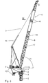
- Fig. 3 to 6 show a first embodiment of an inventive jib device 4, wherein the base unit 2 is shown merely in parts.
- the jib device 4 comprises a sail unit 15.
- the sail unit 15 comprises two wind sails 16.
- the wind sails 16 are oriented perpendicular to the luffing axis 7.
- the wind sails 16 are operable, i.e. retractable. In the parking configuration according to Fig. 3 and 4 , the wind sails 16 are maximallyex-tended.
- the sail unit 15 has a first, maximum surface area, which is defined by the sum of the surface areas of each wind sail 16. Further, the sail unit 15 has a second, minimum surface area. According to the embodiment of Fig. 3 to 6 , the first surface area is approximately three times larger than the second surface area.
- a first luffing angle a 1 is larger than a second luffing angle a 2 of the operative configuration.
- the first jib radius in the parking configuration is smaller than a second jib radius in the operative configuration.
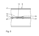
- the wind sails 16 are each integrated inside a lattice frame 17 of the lattice jib 6.
- the lattice frame 17 has a triangular cross section in a plane perpendicular to the jib longitudinal axis 13.
- other cross sections in particular of rectangular or square shape, are possible.
- the wind sails 16 are provided as textiles, which are rolled on a coil or axis 21.
- the coil or axis 21 is oriented perpendicularly to the longitudinal axis 13 of the jib 6.
- the wind sail 16 is provided as a textile and rolled on or packed on said axis 21.
- a free end of the textile of the wind sail 16 is attached to a retracting rod 18.
- the retracting rod is oriented vertically.
- the retracting rod is laterally guided in guiding rails 19.
- the guiding rails 19 can be part of the lattice frame 17 or are firmly attached to the lattice frame 17.
- the setup and in particular the attachment of the wind sail 16 to the lattice jib 6 is robust.
- the wind sails 16 are oriented in parallel to the luffing plane, i.e. perpendicular to the luffing axis 7.
- the textile is rolled on and off the coil 21 depending on the moving direction of the retracting rod 18.
- the moving direction of the retracting 18 is along the jib longitudinal axis 13.
- the drive 20 is in signal connection with an operation unit, which is not shown in the figures.
- the operation unit is preferably arranged in the operator's cabin 9 such that an operator is able to monitor and/or adjust the surface area of the sail unit 15.
- the operation unit comprises a display.
- a control unit is provided, which is not shown in the figures.
- the control unit is in signal connection with the operation unit and the drive 20.
- a sensor unit is provided.
- the sensor unit is not illustrated in the figures.
- the sensor unit comprises at least one sensor element, i.e. a wind sensor for sensing the wind speed and the direction of the wind, a luffing sensor for sensing the luffing angle a and/or a surface area sensor for sensing a current surface area of the sail unit 15.
- a wind sensor for sensing the wind speed and the direction of the wind
- a luffing sensor for sensing the luffing angle a
- a surface area sensor for sensing a current surface area of the sail unit 15.
- the jib device 4 with the sail unit 15 is resistant to a maximum wind speed of 240 km/h if the wind load 14 is directed parallel to the luffing plane, i.e. as illustrated in Fig. 1 and 2 .
- the jib device 4 with the sail unit 15 is resistant to a maximum wind speed 100 km/h with a wind load perpendicularly to the luffing plane.
- FIG. 7 to 8 A further embodiment of a jib device for a crane according the invention is illustrated in Fig. 7 to 8 .
- Components that correspond to those as described in the previous Fig. 1 to 6 have identical reference signs.
- the jib device 22 comprises a lattice jib 6 identical to that of the jib device 4.
- the sail unit 23 is provided with a wind sail 24 made of a rigid material.
- the rigid material is for instance carbon fibre, which is provided in plate form.
- Several carbon fibre plates 25 are connected via a film hinge 26.
- the retracting rod 18 is provided at a maximum distance of a C-shaped container 27.
- the container 27 is provided for storing the plates 25 in a folded arrangement of the operative configuration.
- an inclined angle between two neighbouring plates 25 is maximum, in particular 180°.
- the plates 25 are arranged in one plane, parallel to the luffing plane.
- the orthogonal projection of the wind sail 24 into the luffing plane is maximum.
- the inclined angle between neighbouring plates 25 is reduced and is in particular at most 130°, in particular at most 120°, in particular at most 90° and in particular at most 75°.
- the inclined angle is nearly 0°.
- the plates 25 are parallel to each other arranged inside the container 27.
- the plates 25 are each perpendicularly arranged regarding the luffing plane.
Landscapes
- Engineering & Computer Science (AREA)
- Mechanical Engineering (AREA)
- Jib Cranes (AREA)
Priority Applications (1)
| Application Number | Priority Date | Filing Date | Title |
|---|---|---|---|
| EP15157628.7A EP3064465B1 (fr) | 2015-03-04 | 2015-03-04 | Dispositif de flèche d'une grue comportant une voilure, grue et procédé de fonctionnement de la grue |
Applications Claiming Priority (1)
| Application Number | Priority Date | Filing Date | Title |
|---|---|---|---|
| EP15157628.7A EP3064465B1 (fr) | 2015-03-04 | 2015-03-04 | Dispositif de flèche d'une grue comportant une voilure, grue et procédé de fonctionnement de la grue |
Publications (2)
| Publication Number | Publication Date |
|---|---|
| EP3064465A1 true EP3064465A1 (fr) | 2016-09-07 |
| EP3064465B1 EP3064465B1 (fr) | 2017-10-25 |
Family
ID=52596851
Family Applications (1)
| Application Number | Title | Priority Date | Filing Date |
|---|---|---|---|
| EP15157628.7A Active EP3064465B1 (fr) | 2015-03-04 | 2015-03-04 | Dispositif de flèche d'une grue comportant une voilure, grue et procédé de fonctionnement de la grue |
Country Status (1)
| Country | Link |
|---|---|
| EP (1) | EP3064465B1 (fr) |
Cited By (1)
| Publication number | Priority date | Publication date | Assignee | Title |
|---|---|---|---|---|
| FR3106129A1 (fr) | 2020-01-14 | 2021-07-16 | Manitowoc Crane Group France | Grue à tour à flèche relevable munie d’un système de prise au vent ajustable |
Families Citing this family (3)
| Publication number | Priority date | Publication date | Assignee | Title |
|---|---|---|---|---|
| CN109335965A (zh) * | 2018-10-31 | 2019-02-15 | 中船华南船舶机械有限公司 | 一种智慧起重机安全监控系统及工作方法 |
| US11649142B2 (en) | 2019-08-26 | 2023-05-16 | International Business Machines Corporation | Crane payload stabilization |
| IT202200020724A1 (it) * | 2022-10-07 | 2024-04-07 | Moritsch Cranes S R L | Gru |
Citations (5)
| Publication number | Priority date | Publication date | Assignee | Title |
|---|---|---|---|---|
| DE3345327A1 (de) * | 1983-12-15 | 1985-06-27 | Elba-Werk Maschinen-Gesellschaft Mbh & Co, 7505 Ettlingen | Turmdrehkran mit ausleger und gegenausleger |
| WO2011101132A1 (fr) | 2010-02-19 | 2011-08-25 | Wolffkran Holding Ag | Grue à tour à flèche relevable |
| CN202429925U (zh) * | 2011-11-22 | 2012-09-12 | 中国建筑第六工程局有限公司 | 一种塔式起重机 |
| CN103086280A (zh) * | 2011-11-01 | 2013-05-08 | 浙江虎霸建设机械有限公司 | 自动伸缩式风帆 |
| CN203667857U (zh) * | 2014-01-20 | 2014-06-25 | 中联重科股份有限公司 | 塔机起重臂和具有此塔机起重臂的塔式起重机 |
-
2015
- 2015-03-04 EP EP15157628.7A patent/EP3064465B1/fr active Active
Patent Citations (5)
| Publication number | Priority date | Publication date | Assignee | Title |
|---|---|---|---|---|
| DE3345327A1 (de) * | 1983-12-15 | 1985-06-27 | Elba-Werk Maschinen-Gesellschaft Mbh & Co, 7505 Ettlingen | Turmdrehkran mit ausleger und gegenausleger |
| WO2011101132A1 (fr) | 2010-02-19 | 2011-08-25 | Wolffkran Holding Ag | Grue à tour à flèche relevable |
| CN103086280A (zh) * | 2011-11-01 | 2013-05-08 | 浙江虎霸建设机械有限公司 | 自动伸缩式风帆 |
| CN202429925U (zh) * | 2011-11-22 | 2012-09-12 | 中国建筑第六工程局有限公司 | 一种塔式起重机 |
| CN203667857U (zh) * | 2014-01-20 | 2014-06-25 | 中联重科股份有限公司 | 塔机起重臂和具有此塔机起重臂的塔式起重机 |
Cited By (3)
| Publication number | Priority date | Publication date | Assignee | Title |
|---|---|---|---|---|
| FR3106129A1 (fr) | 2020-01-14 | 2021-07-16 | Manitowoc Crane Group France | Grue à tour à flèche relevable munie d’un système de prise au vent ajustable |
| EP3851405A1 (fr) | 2020-01-14 | 2021-07-21 | Manitowoc Crane Group France | Grue à tour à flèche relevable munie d'un système de prise au vent ajustable |
| US11673776B2 (en) | 2020-01-14 | 2023-06-13 | Manitowoc Crane Group France | Luffing boom tower crane equipped with an adjustable wind load system |
Also Published As
| Publication number | Publication date |
|---|---|
| EP3064465B1 (fr) | 2017-10-25 |
Similar Documents
| Publication | Publication Date | Title |
|---|---|---|
| US9371215B2 (en) | Method for erecting a crane boom | |
| CA2697321C (fr) | Grue telescopique avec dispositif de renforcement autoportant et methode de montage dudit dispositif | |
| EP3527527B1 (fr) | Véhicule de travail doté d'un dispositif de cabine | |
| CA2589048C (fr) | Grue automotrice avec superstructure en forme de portique a tete pivotante | |
| US9725285B2 (en) | Method of raising a crane boom | |
| US8160786B2 (en) | Mobile crane and method for operating a mobile crane | |
| US10472214B2 (en) | Crane and method for monitoring the overload protection of such a crane | |
| EP3064465B1 (fr) | Dispositif de flèche d'une grue comportant une voilure, grue et procédé de fonctionnement de la grue | |
| EP3812337A1 (fr) | Système de tour pour effectuer un travail sur une structure allongée | |
| US20110272377A1 (en) | Crane | |
| US10934140B2 (en) | Tower crane | |
| US10836615B2 (en) | Luffing jib crane with a device for locking the jib in a raised configuration | |
| EP2907786A1 (fr) | Connecteur, combinaison grue et procédé de connexion utilisant celui-ci | |
| US20110272375A1 (en) | Crane and Method for Erecting the Crane | |
| US12202712B2 (en) | Crane and method for monitoring the operation of such a crane | |
| US10202262B2 (en) | Method of operating a crane, and crane | |
| CN107207227A (zh) | 起重机以及用于监测此类起重机的过载保护的方法 | |
| EP2719652B1 (fr) | Dispositif de transport de personnes au moyen d'une grue, et grue dotée d'un dispositif de transport de personnes | |
| EP3902763B1 (fr) | Ensemble de levage et procédé de manipulation d'un élément | |
| EP3231762A1 (fr) | Grue mobile | |
| US6499611B1 (en) | Mobile harbor crane for normal and heavy load operation | |
| JP6235854B2 (ja) | クレーンの組立方法 | |
| US10124993B2 (en) | Method for operating a crane and crane | |
| NL2010554C2 (en) | Crane with connector for erecting a structure. | |
| US20240034602A1 (en) | Crane |
Legal Events
| Date | Code | Title | Description |
|---|---|---|---|
| PUAI | Public reference made under article 153(3) epc to a published international application that has entered the european phase |
Free format text: ORIGINAL CODE: 0009012 |
|
| AK | Designated contracting states |
Kind code of ref document: A1 Designated state(s): AL AT BE BG CH CY CZ DE DK EE ES FI FR GB GR HR HU IE IS IT LI LT LU LV MC MK MT NL NO PL PT RO RS SE SI SK SM TR |
|
| AX | Request for extension of the european patent |
Extension state: BA ME |
|
| 17P | Request for examination filed |
Effective date: 20170217 |
|
| RBV | Designated contracting states (corrected) |
Designated state(s): AL AT BE BG CH CY CZ DE DK EE ES FI FR GB GR HR HU IE IS IT LI LT LU LV MC MK MT NL NO PL PT RO RS SE SI SK SM TR |
|
| GRAP | Despatch of communication of intention to grant a patent |
Free format text: ORIGINAL CODE: EPIDOSNIGR1 |
|
| INTG | Intention to grant announced |
Effective date: 20170703 |
|
| GRAS | Grant fee paid |
Free format text: ORIGINAL CODE: EPIDOSNIGR3 |
|
| GRAA | (expected) grant |
Free format text: ORIGINAL CODE: 0009210 |
|
| AK | Designated contracting states |
Kind code of ref document: B1 Designated state(s): AL AT BE BG CH CY CZ DE DK EE ES FI FR GB GR HR HU IE IS IT LI LT LU LV MC MK MT NL NO PL PT RO RS SE SI SK SM TR |
|
| REG | Reference to a national code |
Ref country code: GB Ref legal event code: FG4D |
|
| REG | Reference to a national code |
Ref country code: CH Ref legal event code: EP |
|
| REG | Reference to a national code |
Ref country code: AT Ref legal event code: REF Ref document number: 939706 Country of ref document: AT Kind code of ref document: T Effective date: 20171115 |
|
| REG | Reference to a national code |
Ref country code: IE Ref legal event code: FG4D |
|
| REG | Reference to a national code |
Ref country code: DE Ref legal event code: R096 Ref document number: 602015005505 Country of ref document: DE |
|
| REG | Reference to a national code |
Ref country code: NL Ref legal event code: MP Effective date: 20171025 |
|
| REG | Reference to a national code |
Ref country code: LT Ref legal event code: MG4D |
|
| REG | Reference to a national code |
Ref country code: AT Ref legal event code: MK05 Ref document number: 939706 Country of ref document: AT Kind code of ref document: T Effective date: 20171025 |
|
| REG | Reference to a national code |
Ref country code: FR Ref legal event code: PLFP Year of fee payment: 4 |
|
| PG25 | Lapsed in a contracting state [announced via postgrant information from national office to epo] |
Ref country code: NL Free format text: LAPSE BECAUSE OF FAILURE TO SUBMIT A TRANSLATION OF THE DESCRIPTION OR TO PAY THE FEE WITHIN THE PRESCRIBED TIME-LIMIT Effective date: 20171025 |
|
| PG25 | Lapsed in a contracting state [announced via postgrant information from national office to epo] |
Ref country code: SE Free format text: LAPSE BECAUSE OF FAILURE TO SUBMIT A TRANSLATION OF THE DESCRIPTION OR TO PAY THE FEE WITHIN THE PRESCRIBED TIME-LIMIT Effective date: 20171025 Ref country code: ES Free format text: LAPSE BECAUSE OF FAILURE TO SUBMIT A TRANSLATION OF THE DESCRIPTION OR TO PAY THE FEE WITHIN THE PRESCRIBED TIME-LIMIT Effective date: 20171025 Ref country code: FI Free format text: LAPSE BECAUSE OF FAILURE TO SUBMIT A TRANSLATION OF THE DESCRIPTION OR TO PAY THE FEE WITHIN THE PRESCRIBED TIME-LIMIT Effective date: 20171025 Ref country code: LT Free format text: LAPSE BECAUSE OF FAILURE TO SUBMIT A TRANSLATION OF THE DESCRIPTION OR TO PAY THE FEE WITHIN THE PRESCRIBED TIME-LIMIT Effective date: 20171025 Ref country code: NO Free format text: LAPSE BECAUSE OF FAILURE TO SUBMIT A TRANSLATION OF THE DESCRIPTION OR TO PAY THE FEE WITHIN THE PRESCRIBED TIME-LIMIT Effective date: 20180125 |
|
| PG25 | Lapsed in a contracting state [announced via postgrant information from national office to epo] |
Ref country code: BG Free format text: LAPSE BECAUSE OF FAILURE TO SUBMIT A TRANSLATION OF THE DESCRIPTION OR TO PAY THE FEE WITHIN THE PRESCRIBED TIME-LIMIT Effective date: 20180125 Ref country code: IS Free format text: LAPSE BECAUSE OF FAILURE TO SUBMIT A TRANSLATION OF THE DESCRIPTION OR TO PAY THE FEE WITHIN THE PRESCRIBED TIME-LIMIT Effective date: 20180225 Ref country code: LV Free format text: LAPSE BECAUSE OF FAILURE TO SUBMIT A TRANSLATION OF THE DESCRIPTION OR TO PAY THE FEE WITHIN THE PRESCRIBED TIME-LIMIT Effective date: 20171025 Ref country code: AT Free format text: LAPSE BECAUSE OF FAILURE TO SUBMIT A TRANSLATION OF THE DESCRIPTION OR TO PAY THE FEE WITHIN THE PRESCRIBED TIME-LIMIT Effective date: 20171025 Ref country code: HR Free format text: LAPSE BECAUSE OF FAILURE TO SUBMIT A TRANSLATION OF THE DESCRIPTION OR TO PAY THE FEE WITHIN THE PRESCRIBED TIME-LIMIT Effective date: 20171025 Ref country code: RS Free format text: LAPSE BECAUSE OF FAILURE TO SUBMIT A TRANSLATION OF THE DESCRIPTION OR TO PAY THE FEE WITHIN THE PRESCRIBED TIME-LIMIT Effective date: 20171025 Ref country code: GR Free format text: LAPSE BECAUSE OF FAILURE TO SUBMIT A TRANSLATION OF THE DESCRIPTION OR TO PAY THE FEE WITHIN THE PRESCRIBED TIME-LIMIT Effective date: 20180126 |
|
| REG | Reference to a national code |
Ref country code: DE Ref legal event code: R097 Ref document number: 602015005505 Country of ref document: DE |
|
| PG25 | Lapsed in a contracting state [announced via postgrant information from national office to epo] |
Ref country code: SK Free format text: LAPSE BECAUSE OF FAILURE TO SUBMIT A TRANSLATION OF THE DESCRIPTION OR TO PAY THE FEE WITHIN THE PRESCRIBED TIME-LIMIT Effective date: 20171025 Ref country code: EE Free format text: LAPSE BECAUSE OF FAILURE TO SUBMIT A TRANSLATION OF THE DESCRIPTION OR TO PAY THE FEE WITHIN THE PRESCRIBED TIME-LIMIT Effective date: 20171025 Ref country code: DK Free format text: LAPSE BECAUSE OF FAILURE TO SUBMIT A TRANSLATION OF THE DESCRIPTION OR TO PAY THE FEE WITHIN THE PRESCRIBED TIME-LIMIT Effective date: 20171025 Ref country code: CY Free format text: LAPSE BECAUSE OF FAILURE TO SUBMIT A TRANSLATION OF THE DESCRIPTION OR TO PAY THE FEE WITHIN THE PRESCRIBED TIME-LIMIT Effective date: 20171025 Ref country code: CZ Free format text: LAPSE BECAUSE OF FAILURE TO SUBMIT A TRANSLATION OF THE DESCRIPTION OR TO PAY THE FEE WITHIN THE PRESCRIBED TIME-LIMIT Effective date: 20171025 |
|
| PG25 | Lapsed in a contracting state [announced via postgrant information from national office to epo] |
Ref country code: RO Free format text: LAPSE BECAUSE OF FAILURE TO SUBMIT A TRANSLATION OF THE DESCRIPTION OR TO PAY THE FEE WITHIN THE PRESCRIBED TIME-LIMIT Effective date: 20171025 Ref country code: SM Free format text: LAPSE BECAUSE OF FAILURE TO SUBMIT A TRANSLATION OF THE DESCRIPTION OR TO PAY THE FEE WITHIN THE PRESCRIBED TIME-LIMIT Effective date: 20171025 Ref country code: PL Free format text: LAPSE BECAUSE OF FAILURE TO SUBMIT A TRANSLATION OF THE DESCRIPTION OR TO PAY THE FEE WITHIN THE PRESCRIBED TIME-LIMIT Effective date: 20171025 |
|
| PLBE | No opposition filed within time limit |
Free format text: ORIGINAL CODE: 0009261 |
|
| STAA | Information on the status of an ep patent application or granted ep patent |
Free format text: STATUS: NO OPPOSITION FILED WITHIN TIME LIMIT |
|
| 26N | No opposition filed |
Effective date: 20180726 |
|
| REG | Reference to a national code |
Ref country code: CH Ref legal event code: PL |
|
| PG25 | Lapsed in a contracting state [announced via postgrant information from national office to epo] |
Ref country code: SI Free format text: LAPSE BECAUSE OF FAILURE TO SUBMIT A TRANSLATION OF THE DESCRIPTION OR TO PAY THE FEE WITHIN THE PRESCRIBED TIME-LIMIT Effective date: 20171025 Ref country code: MC Free format text: LAPSE BECAUSE OF FAILURE TO SUBMIT A TRANSLATION OF THE DESCRIPTION OR TO PAY THE FEE WITHIN THE PRESCRIBED TIME-LIMIT Effective date: 20171025 |
|
| REG | Reference to a national code |
Ref country code: BE Ref legal event code: MM Effective date: 20180331 |
|
| REG | Reference to a national code |
Ref country code: IE Ref legal event code: MM4A |
|
| PG25 | Lapsed in a contracting state [announced via postgrant information from national office to epo] |
Ref country code: LU Free format text: LAPSE BECAUSE OF NON-PAYMENT OF DUE FEES Effective date: 20180304 |
|
| PG25 | Lapsed in a contracting state [announced via postgrant information from national office to epo] |
Ref country code: IE Free format text: LAPSE BECAUSE OF NON-PAYMENT OF DUE FEES Effective date: 20180304 |
|
| PG25 | Lapsed in a contracting state [announced via postgrant information from national office to epo] |
Ref country code: BE Free format text: LAPSE BECAUSE OF NON-PAYMENT OF DUE FEES Effective date: 20180331 Ref country code: CH Free format text: LAPSE BECAUSE OF NON-PAYMENT OF DUE FEES Effective date: 20180331 Ref country code: LI Free format text: LAPSE BECAUSE OF NON-PAYMENT OF DUE FEES Effective date: 20180331 |
|
| PG25 | Lapsed in a contracting state [announced via postgrant information from national office to epo] |
Ref country code: MT Free format text: LAPSE BECAUSE OF NON-PAYMENT OF DUE FEES Effective date: 20180304 |
|
| PG25 | Lapsed in a contracting state [announced via postgrant information from national office to epo] |
Ref country code: TR Free format text: LAPSE BECAUSE OF FAILURE TO SUBMIT A TRANSLATION OF THE DESCRIPTION OR TO PAY THE FEE WITHIN THE PRESCRIBED TIME-LIMIT Effective date: 20171025 |
|
| PG25 | Lapsed in a contracting state [announced via postgrant information from national office to epo] |
Ref country code: PT Free format text: LAPSE BECAUSE OF FAILURE TO SUBMIT A TRANSLATION OF THE DESCRIPTION OR TO PAY THE FEE WITHIN THE PRESCRIBED TIME-LIMIT Effective date: 20171025 |
|
| PG25 | Lapsed in a contracting state [announced via postgrant information from national office to epo] |
Ref country code: MK Free format text: LAPSE BECAUSE OF NON-PAYMENT OF DUE FEES Effective date: 20171025 Ref country code: HU Free format text: LAPSE BECAUSE OF FAILURE TO SUBMIT A TRANSLATION OF THE DESCRIPTION OR TO PAY THE FEE WITHIN THE PRESCRIBED TIME-LIMIT; INVALID AB INITIO Effective date: 20150304 |
|
| PG25 | Lapsed in a contracting state [announced via postgrant information from national office to epo] |
Ref country code: AL Free format text: LAPSE BECAUSE OF FAILURE TO SUBMIT A TRANSLATION OF THE DESCRIPTION OR TO PAY THE FEE WITHIN THE PRESCRIBED TIME-LIMIT Effective date: 20171025 |
|
| P01 | Opt-out of the competence of the unified patent court (upc) registered |
Effective date: 20230530 |
|
| PGFP | Annual fee paid to national office [announced via postgrant information from national office to epo] |
Ref country code: DE Payment date: 20250319 Year of fee payment: 11 |
|
| PGFP | Annual fee paid to national office [announced via postgrant information from national office to epo] |
Ref country code: FR Payment date: 20250325 Year of fee payment: 11 |
|
| PGFP | Annual fee paid to national office [announced via postgrant information from national office to epo] |
Ref country code: IT Payment date: 20250325 Year of fee payment: 11 Ref country code: GB Payment date: 20250321 Year of fee payment: 11 |