EP3064653A1 - Hydrauliksystem für eine konstruktionsvorrichtung mit schwimmfunktion - Google Patents
Hydrauliksystem für eine konstruktionsvorrichtung mit schwimmfunktion Download PDFInfo
- Publication number
- EP3064653A1 EP3064653A1 EP13896202.2A EP13896202A EP3064653A1 EP 3064653 A1 EP3064653 A1 EP 3064653A1 EP 13896202 A EP13896202 A EP 13896202A EP 3064653 A1 EP3064653 A1 EP 3064653A1
- Authority
- EP
- European Patent Office
- Prior art keywords
- hydraulic
- hydraulic cylinder
- working device
- float function
- control valve
- Prior art date
- Legal status (The legal status is an assumption and is not a legal conclusion. Google has not performed a legal analysis and makes no representation as to the accuracy of the status listed.)
- Withdrawn
Links
Images


Classifications
-
- E—FIXED CONSTRUCTIONS
- E02—HYDRAULIC ENGINEERING; FOUNDATIONS; SOIL SHIFTING
- E02F—DREDGING; SOIL-SHIFTING
- E02F9/00—Component parts of dredgers or soil-shifting machines, not restricted to one of the kinds covered by groups E02F3/00 - E02F7/00
- E02F9/20—Drives; Control devices
- E02F9/22—Hydraulic or pneumatic drives
- E02F9/2203—Arrangements for controlling the attitude of actuators, e.g. speed, floating function
-
- E—FIXED CONSTRUCTIONS
- E02—HYDRAULIC ENGINEERING; FOUNDATIONS; SOIL SHIFTING
- E02F—DREDGING; SOIL-SHIFTING
- E02F3/00—Dredgers; Soil-shifting machines
- E02F3/04—Dredgers; Soil-shifting machines mechanically-driven
- E02F3/28—Dredgers; Soil-shifting machines mechanically-driven with digging tools mounted on a dipper- or bucket-arm, i.e. there is either one arm or a pair of arms, e.g. dippers, buckets
- E02F3/36—Component parts
- E02F3/42—Drives for dippers, buckets, dipper-arms or bucket-arms
- E02F3/425—Drive systems for dipper-arms, backhoes or the like
-
- E—FIXED CONSTRUCTIONS
- E02—HYDRAULIC ENGINEERING; FOUNDATIONS; SOIL SHIFTING
- E02F—DREDGING; SOIL-SHIFTING
- E02F3/00—Dredgers; Soil-shifting machines
- E02F3/04—Dredgers; Soil-shifting machines mechanically-driven
- E02F3/76—Graders, bulldozers, or the like with scraper plates or ploughshare-like elements; Levelling scarifying devices
- E02F3/80—Component parts
- E02F3/84—Drives or control devices therefor, e.g. hydraulic drive systems
- E02F3/844—Drives or control devices therefor, e.g. hydraulic drive systems for positioning the blade, e.g. hydraulically
-
- E—FIXED CONSTRUCTIONS
- E02—HYDRAULIC ENGINEERING; FOUNDATIONS; SOIL SHIFTING
- E02F—DREDGING; SOIL-SHIFTING
- E02F9/00—Component parts of dredgers or soil-shifting machines, not restricted to one of the kinds covered by groups E02F3/00 - E02F7/00
- E02F9/20—Drives; Control devices
- E02F9/22—Hydraulic or pneumatic drives
- E02F9/2278—Hydraulic circuits
- E02F9/2285—Pilot-operated systems
-
- F—MECHANICAL ENGINEERING; LIGHTING; HEATING; WEAPONS; BLASTING
- F15—FLUID-PRESSURE ACTUATORS; HYDRAULICS OR PNEUMATICS IN GENERAL
- F15B—SYSTEMS ACTING BY MEANS OF FLUIDS IN GENERAL; FLUID-PRESSURE ACTUATORS, e.g. SERVOMOTORS; DETAILS OF FLUID-PRESSURE SYSTEMS, NOT OTHERWISE PROVIDED FOR
- F15B11/00—Servomotor systems without provision for follow-up action; Circuits therefor
- F15B11/02—Systems essentially incorporating special features for controlling the speed or actuating force of an output member
- F15B11/028—Systems essentially incorporating special features for controlling the speed or actuating force of an output member for controlling the actuating force
-
- E—FIXED CONSTRUCTIONS
- E02—HYDRAULIC ENGINEERING; FOUNDATIONS; SOIL SHIFTING
- E02F—DREDGING; SOIL-SHIFTING
- E02F3/00—Dredgers; Soil-shifting machines
- E02F3/04—Dredgers; Soil-shifting machines mechanically-driven
- E02F3/28—Dredgers; Soil-shifting machines mechanically-driven with digging tools mounted on a dipper- or bucket-arm, i.e. there is either one arm or a pair of arms, e.g. dippers, buckets
- E02F3/30—Dredgers; Soil-shifting machines mechanically-driven with digging tools mounted on a dipper- or bucket-arm, i.e. there is either one arm or a pair of arms, e.g. dippers, buckets with a dipper-arm pivoted on a cantilever beam, i.e. boom
- E02F3/32—Dredgers; Soil-shifting machines mechanically-driven with digging tools mounted on a dipper- or bucket-arm, i.e. there is either one arm or a pair of arms, e.g. dippers, buckets with a dipper-arm pivoted on a cantilever beam, i.e. boom working downwardly and towards the machine, e.g. with backhoes
-
- E—FIXED CONSTRUCTIONS
- E02—HYDRAULIC ENGINEERING; FOUNDATIONS; SOIL SHIFTING
- E02F—DREDGING; SOIL-SHIFTING
- E02F3/00—Dredgers; Soil-shifting machines
- E02F3/04—Dredgers; Soil-shifting machines mechanically-driven
- E02F3/76—Graders, bulldozers, or the like with scraper plates or ploughshare-like elements; Levelling scarifying devices
- E02F3/7609—Scraper blade mounted forwardly of the tractor on a pair of pivoting arms which are linked to the sides of the tractor, e.g. bulldozers
-
- F—MECHANICAL ENGINEERING; LIGHTING; HEATING; WEAPONS; BLASTING
- F15—FLUID-PRESSURE ACTUATORS; HYDRAULICS OR PNEUMATICS IN GENERAL
- F15B—SYSTEMS ACTING BY MEANS OF FLUIDS IN GENERAL; FLUID-PRESSURE ACTUATORS, e.g. SERVOMOTORS; DETAILS OF FLUID-PRESSURE SYSTEMS, NOT OTHERWISE PROVIDED FOR
- F15B2211/00—Circuits for servomotor systems
- F15B2211/30—Directional control
- F15B2211/305—Directional control characterised by the type of valves
- F15B2211/3056—Assemblies of multiple valves
- F15B2211/30565—Assemblies of multiple valves having multiple valves for a single output member, e.g. for creating higher valve function by use of multiple valves like two 2/2-valves replacing a 5/3-valve
- F15B2211/3058—Assemblies of multiple valves having multiple valves for a single output member, e.g. for creating higher valve function by use of multiple valves like two 2/2-valves replacing a 5/3-valve having additional valves for interconnecting the fluid chambers of a double-acting actuator, e.g. for regeneration mode or for floating mode
-
- F—MECHANICAL ENGINEERING; LIGHTING; HEATING; WEAPONS; BLASTING
- F15—FLUID-PRESSURE ACTUATORS; HYDRAULICS OR PNEUMATICS IN GENERAL
- F15B—SYSTEMS ACTING BY MEANS OF FLUIDS IN GENERAL; FLUID-PRESSURE ACTUATORS, e.g. SERVOMOTORS; DETAILS OF FLUID-PRESSURE SYSTEMS, NOT OTHERWISE PROVIDED FOR
- F15B2211/00—Circuits for servomotor systems
- F15B2211/70—Output members, e.g. hydraulic motors or cylinders or control therefor
- F15B2211/71—Multiple output members, e.g. multiple hydraulic motors or cylinders
- F15B2211/7114—Multiple output members, e.g. multiple hydraulic motors or cylinders with direct connection between the chambers of different actuators
- F15B2211/7128—Multiple output members, e.g. multiple hydraulic motors or cylinders with direct connection between the chambers of different actuators the chambers being connected in parallel
Definitions
- the present invention relates to a hydraulic system of construction equipment having a float function, and more particularly, to a hydraulic apparatus for a construction machine having a float function, which can improve reduction effects of hydraulic elements and manufacturing costs by making a working device descend without a float valve when a float function switch is operated to perform leveling or grading work at a construction site.
- a construction machine including an excavator or a dozer may be used to perform leveling or grading work at a construction site.
- the excavator may be driven to make a boom descend so that a bucket comes in contact with the ground, and the dozer equipment may be driven to make a dozer blade device that is mounted on an arm or a tilt arm come in contact with the ground.
- Korean Patent Application Publication No. 2010-0134827 discloses a hydraulic system for a construction machine capable of implementing a float function that makes it possible to perform leveling or grading work.
- a logic poppet for performing a holding function is provided inside a float valve, and float and holding valves are unified to simplify the structure of the valves and hydraulic pipes connecting the valves to each other.
- the float valve between the working device, such as the boom cylinder or the dozer blade cylinder, and the hydraulic control valve when the construction machine including the excavator or the dozer performs the float function, and this causes the hydraulic elements related to the float valve and the manufacturing costs thereof to be increased.
- the present invention has been made to solve the aforementioned problems occurring in the related art, and one subject to be achieved by the present invention is to provide a hydraulic apparatus for a construction machine having a float function, which makes it possible to manufacture compact hydraulic circuit and hydraulic pipe at reduced manufacturing costs by performing a float function of a working device including a boom or a dozer blade without requirement for a float valve.
- Another subject to be achieved by the present invention is to provide a hydraulic apparatus for a construction machine having a float function, which can effectively perform a float function of a working device by opening a flow path for making the working device descend through a pilot signal that is output through a remote control valve when the float function is performed and making hydraulic fluid of a working device hydraulic cylinder return to a hydraulic tank.
- a hydraulic apparatus for a construction machine having a float function which includes a hydraulic pump and a pilot pump supplying hydraulic fluid to drive a working device; a remote control valve outputting a pilot signal corresponding to an operation amount of an operation lever; a working device hydraulic cylinder connected to the hydraulic pump; a main control valve installed in a discharge flow path of the hydraulic pump to control a start, stop, and direction change of the hydraulic cylinder when a spool is shifted; a solenoid valve shifted to an opening position when a float function switch is turned on; and a two-stage port relief valve installed in a flow path between the main control valve and the working device hydraulic cylinder, and shifted to return the hydraulic fluid in a large chamber of the hydraulic cylinder to a hydraulic tank so that the working device descends when the float function switch is operated to be turned on.
- the hydraulic cylinder may be composed of a boom cylinder, and the two-stage port relief valve may include a signal pressure port into which pilot signal pressure is introduced through the remote control valve when the float function switch is operated to effectively perform the float function.
- the hydraulic cylinder may be composed of a hydraulic cylinder for a dozer blade device to effectively perform the float function of dozer equipment.
- the two-stage port relief valve may be set to a minimum relief pressure state by the pilot signal pressure to open an inner flow path thereof, and thus the hydraulic fluid in the hydraulic cylinder for the boom or the dozer blade device may return to the hydraulic tank to perform the float function.
- a hydraulic apparatus for a construction machine having a float function which includes a hydraulic pump and a pilot pump supplying hydraulic fluid to drive a working device; a remote control valve outputting a pilot signal corresponding to an operation amount of an operation lever; a working device hydraulic cylinder connected to the hydraulic pump; a main control valve installed in a discharge flow path of the hydraulic pump to control a start, stop, and direction change of the hydraulic cylinder when a spool is shifted; a solenoid valve shifted to an opening position when a float function switch is turned on; and an on-off check valve installed in a flow path between the main control valve and the working device hydraulic cylinder, and shifted to return the hydraulic fluid in a small chamber of the hydraulic cylinder to a hydraulic tank so that the working device descends when the float function switch is operated.
- the hydraulic apparatus for a construction machine having a float function when the float function is inactivated, the maximum relief pressure is maintained, whereas when the float function is activated, the inner flow path of the 2-stage port relief valve is opened by the pilot signal that is output through the remote control valve to make the hydraulic fluid in the working device hydraulic cylinder return to the hydraulic tank, and thus the leveling or grading work using the working device can be effectively performed.
- the float function of the working device including the boom or the dozer blade is performed without the float valve, and thus it becomes possible to design compact hydraulic circuit and hydraulic pipe and to save the manufacturing costs.
- Fig. 1 is a schematic hydraulic circuit diagram of a hydraulic apparatus for a construction machine having a float function according to an embodiment of the present invention
- Fig. 2 is a schematic hydraulic circuit diagram of a hydraulic apparatus for a construction machine having a float function according to another embodiment of the present invention
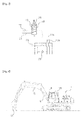
- Fig. 3 is a diagram of a main part of a hydraulic apparatus for a construction machine having a float function according to still another embodiment of the present invention
- Fig. 4 is a schematic perspective view of an excavator provided with a hydraulic apparatus for a construction machine having a float function according to the present invention.
- drawing reference numeral "1" denotes an excavator according to an embodiment of the present invention
- "3” denotes an operation lever
- "4" denotes a remote control valve
- "5" denotes a working device hydraulic cylinder that is driven when a float function is activated
- "10” denotes a solenoid valve
- "12” denotes a 2-stage port relief valve.
- the hydraulic apparatus for a construction machine having a float function is applied to an excavator that performs leveling or grading work to level the ground or a construction machine that includes a dozer or a grader, and performs floating operation to make a working device approach the ground in accordance with activation of the float function.
- a hydraulic apparatus for a construction machine having a float function includes a hydraulic pump 1 and a pilot pump 2 supplying hydraulic fluid to drive a working device; a remote control valve 4 outputting a pilot signal corresponding to an operation amount of an operation lever 3; a working device hydraulic cylinder 5 connected to the hydraulic pump 1; and a main control valve 7 installed in a discharge flow path 6 of the hydraulic pump 1 to control a start, stop, and direction change of the hydraulic cylinder 5 when a spool is shifted.
- the main control valve 7 may have a plurality of hydraulic control valves built therein to drive a working device, such as a bucket or an arm.
- the working device hydraulic cylinder 5 may include a pair of hydraulic cylinders 5a and 5b to perform ascending and descending of a boom, and in the case of dozer equipment, a dozer blade working device that is required for the float operation may include a hydraulic cylinder 5c. This will be described in more detail later.
- a float function switch 8 may be provided in a cab, and if an operator operates the switch, an electrical signal or a pilot signal for controlling opening and closing of the valve that is required to perform the float function may be output from the float function switch 8.
- a solenoid valve 10 is shifted to an opening position when the float function switch 8 is turned on, and is shifted to a closing position when the float function switch 8 is turned off.
- the solenoid valve 10 is configured to include a signal pressure port 19 into which a valve control signal is introduced when the float function switch 8 is operated to open or close the valve, and an inner flow path 18 for connecting pilot signal pressure that is provided through the remote control valve 4.
- the hydraulic apparatus for a construction machine having a float function further includes a two-stage port relief valve 12 installed in a flow path 11 between the main control valve 7 and the working device hydraulic cylinder 5, and shifted to return the hydraulic fluid in a large chamber of the hydraulic cylinder 5 to a hydraulic tank 15 so that the working device descends when the float function switch 8 is operated to be turned on.
- the 2-stage port relief valve 12 includes a signal pressure port 13 into which the pilot signal pressure is introduced through the remote control valve 4 when the float function switch 8 is operated.
- the 2-stage port relief valve 12 is shifted to open the inner flow path 14 in a state where the minimum relief pressure is set by the pilot signal pressure when the float function for the working device is performed or activated, and thus the hydraulic fluid of the hydraulic cylinder 5 returns to the hydraulic tank 15.
- valve opening ratio of the 2-stage port relief valve 12 may be changed to the minimum relief pressure state by the valve control signal that is provided from an outside, for example, the pilot signal pressure.
- the 2-stage port relief valve 12 is maintained in the predetermined maximum relief pressure state, and thus the inner flow path 14 is closed.
- a relief valve 16 may be further installed to drain hydraulic pressure between the hydraulic cylinder 5 and the main control valve 7 to the hydraulic tank 15 if the hydraulic pressure exceeds predetermined system pressure when the working device ascends or descends.
- Fig. 2 is a hydraulic circuit diagram explaining a state where a hydraulic apparatus for a construction machine having a float function according to another embodiment of the present invention is applied to dozer equipment.
- the 2-stage port relief valve 10 is installed in the flow path 11 between the main control valve 7 and the working device hydraulic cylinder 5, and if the float function switch 8 is operated in a neutral position of the main control valve 7, the 2-stage port relief valve 10 is shifted to return the hydraulic fluid of the hydraulic cylinder 5 to the hydraulic tank 15 in response to the pilot signal pressure that is provided through the solenoid valve 10.
- the solenoid valve 10 may be operated to provide the pilot signal pressure for opening or closing the valve when the float function switch 8 is operated in the neutral position of the main control valve 7.
- the hydraulic apparatus for a construction device having a float function includes an on-off check valve 23 installed in a flow path 11a or 11b between the main control valve 7 and the working device hydraulic cylinder 5c, and shifted to return the hydraulic fluid of the hydraulic cylinder 5c to the hydraulic tank 15 so that the working device descends when the float function switch 8 is operated.
- the hydraulic cylinder 5c is used for ascending/descending or tilt driving of the dozer blade.
- the two-stage port relief valve 12 or the on-off check valve 23 may be variously applied to return the hydraulic fluid of the large chamber 17a or the small chamber 17b of the hydraulic cylinder 5, which is required in accordance with the working device, to the hydraulic tank 15.
- the operator may control the driving of a working device including a boom B after turning off the float function switch 8.
- pilot hydraulic fluid that is discharged from a pilot pump Pi is supplied to the main control valve 7 through a pilot flow path 2b to shift the spool of the main control valve 7.
- the hydraulic fluid that is discharged from the hydraulic pump 1 is supplied to the large chamber and the small chamber of the hydraulic cylinder 5 through the discharge flow path 6 and the main control valve 7 to drive the working device.
- the 2-stage port relief valve 12 according to the present invention is maintained in the predetermined maximum relief pressure state, and the inner flow path 14 is closed to maintain the valve close state.
- the hydraulic fluid is supplied to the pair of hydraulic cylinders 5a and 5b to drive the boom, but in the case of other working devices that require the float function, the hydraulic cylinder 5c may be independently operated.
- the main control valve 7 is positioned in the neutral state, and the boom working device or the dozer blade working device may descend to approach the ground in accordance with the operation of the float function switch 8.
- the operator operates the float function switch 8 that is installed inside the cab 25 to perform the float function.
- the pilot hydraulic fluid that is discharged from the pilot pump 2 is supplied to a signal pressure flow path 22 through the remote control valve 4.
- the electrical signal or the pilot signal for opening or closing the valve is applied to the signal pressure port 19 of the solenoid valve 10, and thus the solenoid valve 10 is shifted to the opening position of the inner flow path 18.
- the signal pressure of the pilot hydraulic fluid that is supplied to the signal pressure flow path 22 through the remote control valve 4 is provided to the inner flow path 14 of the 2-stage port relief valve 12 through the inner flow path 18 of the solenoid valve 10.
- the inner flow path 14 of the 2-stage port relief valve 12 is shifted to the opening position by the pressure of the pilot hydraulic fluid that is supplied to the signal pressure port 13.
- the hydraulic fluid of the dozer blade hydraulic cylinder 5c returns to the hydraulic tank 15 through the return flow path 20 in the neutral position of the main control valve 7, and thus the dozer blade working device descends to approach the ground to perform the leveling and grading work or grading work.
- the on-off check valve 23 may be constructed instead of the 2-stage port relief valve 12. In this case, as illustrated in Fig. 3 , if the float function switch 8 is operated to be turned on, the signal pressure of the pilot hydraulic fluid that is supplied to the signal pressure flow path 22 through the remote control valve 4 is supplied to the on-off check valve 23 through the inner flow path 18 of the solenoid valve 10.
- the on-off check valve 23 is opened, and the hydraulic pressure of the working device hydraulic cylinder 5 returns to the hydraulic tank 15 through the return flow path 20 in the neutral position of the main control valve 7.
- the 2-stage port relief valve 12 or the on-off check valve 23 returns the hydraulic pressure of the working device hydraulic cylinder to the hydraulic tank 15, and thus the float function of the working device can be smoothly performed.
- the hydraulic apparatus for a construction machine having a float function since the float function of the boom or dozer blade working device is performed through the control of the simple hydraulic apparatus, the leveling work or the grading work that is required at the construction site can be efficiently performed.
Landscapes
- Engineering & Computer Science (AREA)
- General Engineering & Computer Science (AREA)
- Mining & Mineral Resources (AREA)
- Civil Engineering (AREA)
- Structural Engineering (AREA)
- Mechanical Engineering (AREA)
- Physics & Mathematics (AREA)
- Fluid Mechanics (AREA)
- Operation Control Of Excavators (AREA)
- Fluid-Pressure Circuits (AREA)
Applications Claiming Priority (1)
| Application Number | Priority Date | Filing Date | Title |
|---|---|---|---|
| PCT/KR2013/009751 WO2015064782A1 (ko) | 2013-10-30 | 2013-10-30 | 플로트 기능을 구비한 건설장비용 유압장치 |
Publications (2)
| Publication Number | Publication Date |
|---|---|
| EP3064653A1 true EP3064653A1 (de) | 2016-09-07 |
| EP3064653A4 EP3064653A4 (de) | 2017-06-14 |
Family
ID=53004370
Family Applications (1)
| Application Number | Title | Priority Date | Filing Date |
|---|---|---|---|
| EP13896202.2A Withdrawn EP3064653A4 (de) | 2013-10-30 | 2013-10-30 | Hydrauliksystem für eine konstruktionsvorrichtung mit schwimmfunktion |
Country Status (4)
| Country | Link |
|---|---|
| US (1) | US20160251830A1 (de) |
| EP (1) | EP3064653A4 (de) |
| CN (1) | CN105683451A (de) |
| WO (1) | WO2015064782A1 (de) |
Cited By (1)
| Publication number | Priority date | Publication date | Assignee | Title |
|---|---|---|---|---|
| GB2599738A (en) * | 2020-10-06 | 2022-04-13 | Caterpillar Work Tools Bv | Automatic pressure release |
Families Citing this family (8)
| Publication number | Priority date | Publication date | Assignee | Title |
|---|---|---|---|---|
| DE112013006501T5 (de) * | 2013-01-24 | 2016-03-31 | Volvo Construction Equipment Ab | Vorrichtung und Verfahren zum Steuern einer Flussrate bei Baumaschinen |
| CN106149795B (zh) * | 2016-08-24 | 2018-07-27 | 四川邦立重机有限责任公司 | 挖掘机动臂液压控制系统 |
| CN106468062B (zh) * | 2016-09-22 | 2018-09-11 | 柳州柳工挖掘机有限公司 | 具有推土铲浮动功能的挖掘机推土液压系统 |
| CN110500343A (zh) * | 2019-08-26 | 2019-11-26 | 柳州柳工挖掘机有限公司 | 挖掘机推土铲液压系统 |
| CN117500986A (zh) | 2021-06-28 | 2024-02-02 | 斗山山猫北美公司 | 用于控制挖掘机和其他动力机器的系统和方法 |
| CN113882444B (zh) * | 2021-10-29 | 2023-03-14 | 徐州徐工挖掘机械有限公司 | 一种带有推土铲浮动功能的推土液压系统以及挖掘机 |
| US12410574B2 (en) * | 2022-08-22 | 2025-09-09 | Deere & Company | Ground compaction sensing system and method for a work machine |
| CN115748855B (zh) * | 2022-12-16 | 2023-06-30 | 徐州徐工挖掘机械有限公司 | 一种挖掘机动臂浮动液压控制系统及控制方法 |
Family Cites Families (12)
| Publication number | Priority date | Publication date | Assignee | Title |
|---|---|---|---|---|
| JP2514915B2 (ja) * | 1989-03-08 | 1996-07-10 | 油谷重工株式会社 | 建設機械のブ―ム用フロ―ト回路 |
| JP3684268B2 (ja) * | 1996-04-23 | 2005-08-17 | コベルコ建機エンジニアリング株式会社 | 油圧シリンダのフローティング装置 |
| US6092454A (en) * | 1998-07-23 | 2000-07-25 | Caterpillar Inc. | Controlled float circuit for an actuator |
| JP2004301214A (ja) * | 2003-03-31 | 2004-10-28 | Hitachi Constr Mach Co Ltd | 作業用車両の油圧駆動装置 |
| FR2863634A1 (fr) * | 2003-12-16 | 2005-06-17 | Volvo Constr Equip Holding Se | Engin de travaux publics |
| US7478489B2 (en) * | 2006-06-01 | 2009-01-20 | Deere & Company | Control system for an electronic float feature for a loader |
| JP2009155893A (ja) * | 2007-12-26 | 2009-07-16 | Kobelco Contstruction Machinery Ltd | ショベルのドーザ装置 |
| US8474254B2 (en) * | 2008-11-06 | 2013-07-02 | Purdue Research Foundation | System and method for enabling floating of earthmoving implements |
| KR101500744B1 (ko) * | 2008-11-19 | 2015-03-09 | 두산인프라코어 주식회사 | 건설기계의 붐 실린더 제어회로 |
| KR101112133B1 (ko) * | 2009-06-16 | 2012-02-22 | 볼보 컨스트럭션 이큅먼트 에이비 | 플로트 기능을 갖는 건설장비용 유압시스템 |
| CN201771512U (zh) * | 2010-08-25 | 2011-03-23 | 一重集团大连设计研究院有限公司 | 盾构机主动铰接缸液压控制系统 |
| CN202945636U (zh) * | 2012-12-04 | 2013-05-22 | 徐工集团工程机械股份有限公司科技分公司 | 具有浮动功能的装载机液压系统 |
-
2013
- 2013-10-30 CN CN201380080624.2A patent/CN105683451A/zh active Pending
- 2013-10-30 EP EP13896202.2A patent/EP3064653A4/de not_active Withdrawn
- 2013-10-30 US US15/032,686 patent/US20160251830A1/en not_active Abandoned
- 2013-10-30 WO PCT/KR2013/009751 patent/WO2015064782A1/ko not_active Ceased
Cited By (3)
| Publication number | Priority date | Publication date | Assignee | Title |
|---|---|---|---|---|
| GB2599738A (en) * | 2020-10-06 | 2022-04-13 | Caterpillar Work Tools Bv | Automatic pressure release |
| GB2599738B (en) * | 2020-10-06 | 2023-07-12 | Caterpillar Work Tools Bv | Automatic pressure release |
| US12601149B2 (en) | 2020-10-06 | 2026-04-14 | Caterpillar Work Tools B.V. | Automatic pressure release |
Also Published As
| Publication number | Publication date |
|---|---|
| US20160251830A1 (en) | 2016-09-01 |
| WO2015064782A1 (ko) | 2015-05-07 |
| EP3064653A4 (de) | 2017-06-14 |
| CN105683451A (zh) | 2016-06-15 |
Similar Documents
| Publication | Publication Date | Title |
|---|---|---|
| EP3064653A1 (de) | Hydrauliksystem für eine konstruktionsvorrichtung mit schwimmfunktion | |
| EP2264250A2 (de) | Hydrauliksystem für Baumaschinen mit Glättfunktion | |
| EP2071195A2 (de) | Hydraulische Schaltung mit durch externen Steuerdruck angesteuerten Lasthalteventilen | |
| EP3255284B1 (de) | Durchflussregelventil für eine baumaschine | |
| ATE377676T1 (de) | Hydraulische steuervorrichtung für hydraulikbagger | |
| JP2005265016A (ja) | 作業機械の油圧制御装置 | |
| EP2302222A1 (de) | Mehrwegesteuerventil mit schaufelparallelbewegungsfunktion | |
| CN101270766B (zh) | 在重型设备行进过程中防止铲斗从铲斗支座分离的液压回路 | |
| JP5873684B2 (ja) | 作業車両の油圧駆動装置 | |
| EP1380756A4 (de) | Druckmittel-schaltkreis | |
| KR940005896A (ko) | 백호장치의 유압회로구조 | |
| EP2573407A1 (de) | Hydraulisches steuerventil für eine baumaschine | |
| EP3064654A1 (de) | Durchflussregelventil für baumaschinen mit fliessfunktion | |
| EP3249114B1 (de) | Steuerventil für eine baumaschine | |
| US9482214B2 (en) | Hydraulic circuit for controlling booms of construction equipment | |
| JP2008039042A (ja) | 油圧アクチュエータ回路の負荷保持装置 | |
| JP2015169250A (ja) | 建設機械の油圧駆動システム | |
| CN112112867B (zh) | 液控式排气阀单元、液控排气式卷扬控制系统和卷扬机 | |
| JP5651212B2 (ja) | 非常用の油圧源装置を用いた非常駆動回路 | |
| JP4354419B2 (ja) | 圧力補償弁を備えた流量制御弁 | |
| JP2014040909A5 (de) | ||
| EP3009690A1 (de) | Durchflussregelventil für eine baumaschine | |
| JP2017155931A (ja) | 油圧装置及び該油圧装置の油圧シリンダ内の異物を除去する方法 | |
| EP3821136B1 (de) | Hydraulische maschine umfassend einen hydraulikkreis | |
| CN210003586U (zh) | 一种工程机械液压控制系统 |
Legal Events
| Date | Code | Title | Description |
|---|---|---|---|
| PUAI | Public reference made under article 153(3) epc to a published international application that has entered the european phase |
Free format text: ORIGINAL CODE: 0009012 |
|
| 17P | Request for examination filed |
Effective date: 20160420 |
|
| AK | Designated contracting states |
Kind code of ref document: A1 Designated state(s): AL AT BE BG CH CY CZ DE DK EE ES FI FR GB GR HR HU IE IS IT LI LT LU LV MC MK MT NL NO PL PT RO RS SE SI SK SM TR |
|
| AX | Request for extension of the european patent |
Extension state: BA ME |
|
| DAX | Request for extension of the european patent (deleted) | ||
| A4 | Supplementary search report drawn up and despatched |
Effective date: 20170516 |
|
| RIC1 | Information provided on ipc code assigned before grant |
Ipc: F15B 11/02 20060101ALI20170510BHEP Ipc: F15B 13/02 20060101ALI20170510BHEP Ipc: E02F 9/22 20060101AFI20170510BHEP |
|
| STAA | Information on the status of an ep patent application or granted ep patent |
Free format text: STATUS: THE APPLICATION HAS BEEN WITHDRAWN |
|
| 18W | Application withdrawn |
Effective date: 20170609 |