EP3064691A1 - Système de blocage de porte - Google Patents
Système de blocage de porte Download PDFInfo
- Publication number
- EP3064691A1 EP3064691A1 EP15203030.0A EP15203030A EP3064691A1 EP 3064691 A1 EP3064691 A1 EP 3064691A1 EP 15203030 A EP15203030 A EP 15203030A EP 3064691 A1 EP3064691 A1 EP 3064691A1
- Authority
- EP
- European Patent Office
- Prior art keywords
- locking arrangement
- additional element
- housing
- holder
- door
- Prior art date
- Legal status (The legal status is an assumption and is not a legal conclusion. Google has not performed a legal analysis and makes no representation as to the accuracy of the status listed.)
- Granted
Links
Images




Classifications
-
- E—FIXED CONSTRUCTIONS
- E05—LOCKS; KEYS; WINDOW OR DOOR FITTINGS; SAFES
- E05F—DEVICES FOR MOVING WINGS INTO OPEN OR CLOSED POSITION; CHECKS FOR WINGS; WING FITTINGS NOT OTHERWISE PROVIDED FOR, CONCERNED WITH THE FUNCTIONING OF THE WING
- E05F3/00—Closers or openers with braking devices, e.g. checks; Construction of pneumatic or liquid braking devices
- E05F3/22—Additional arrangements for closers, e.g. for holding the wing in opened or other position
- E05F3/221—Mechanical power-locks, e.g. for holding the wing open or for free-moving zones
- E05F3/222—Mechanical power-locks, e.g. for holding the wing open or for free-moving zones electrically operated
-
- E—FIXED CONSTRUCTIONS
- E05—LOCKS; KEYS; WINDOW OR DOOR FITTINGS; SAFES
- E05C—BOLTS OR FASTENING DEVICES FOR WINGS, SPECIALLY FOR DOORS OR WINDOWS
- E05C17/00—Devices for holding wings open; Devices for limiting opening of wings or for holding wings open by a movable member extending between frame and wing; Braking devices, stops or buffers, combined therewith
- E05C17/02—Devices for holding wings open; Devices for limiting opening of wings or for holding wings open by a movable member extending between frame and wing; Braking devices, stops or buffers, combined therewith by mechanical means
- E05C17/04—Devices for holding wings open; Devices for limiting opening of wings or for holding wings open by a movable member extending between frame and wing; Braking devices, stops or buffers, combined therewith by mechanical means with a movable bar or equivalent member extending between frame and wing
- E05C17/12—Devices for holding wings open; Devices for limiting opening of wings or for holding wings open by a movable member extending between frame and wing; Braking devices, stops or buffers, combined therewith by mechanical means with a movable bar or equivalent member extending between frame and wing consisting of a single rod
- E05C17/24—Devices for holding wings open; Devices for limiting opening of wings or for holding wings open by a movable member extending between frame and wing; Braking devices, stops or buffers, combined therewith by mechanical means with a movable bar or equivalent member extending between frame and wing consisting of a single rod pivoted at one end, and with the other end running along a guide member
- E05C17/28—Devices for holding wings open; Devices for limiting opening of wings or for holding wings open by a movable member extending between frame and wing; Braking devices, stops or buffers, combined therewith by mechanical means with a movable bar or equivalent member extending between frame and wing consisting of a single rod pivoted at one end, and with the other end running along a guide member with braking, clamping or securing means at the connection to the guide member
-
- E—FIXED CONSTRUCTIONS
- E05—LOCKS; KEYS; WINDOW OR DOOR FITTINGS; SAFES
- E05B—LOCKS; ACCESSORIES THEREFOR; HANDCUFFS
- E05B47/00—Operating or controlling locks or other fastening devices by electric or magnetic means
- E05B2047/0048—Circuits, feeding, monitoring
- E05B2047/0057—Feeding
- E05B2047/0058—Feeding by batteries
-
- E—FIXED CONSTRUCTIONS
- E05—LOCKS; KEYS; WINDOW OR DOOR FITTINGS; SAFES
- E05C—BOLTS OR FASTENING DEVICES FOR WINGS, SPECIALLY FOR DOORS OR WINDOWS
- E05C17/00—Devices for holding wings open; Devices for limiting opening of wings or for holding wings open by a movable member extending between frame and wing; Braking devices, stops or buffers, combined therewith
- E05C17/56—Devices for holding wings open; Devices for limiting opening of wings or for holding wings open by a movable member extending between frame and wing; Braking devices, stops or buffers, combined therewith by magnetic or electromagnetic attraction or operated by electric or electromagnetic means
-
- E—FIXED CONSTRUCTIONS
- E05—LOCKS; KEYS; WINDOW OR DOOR FITTINGS; SAFES
- E05F—DEVICES FOR MOVING WINGS INTO OPEN OR CLOSED POSITION; CHECKS FOR WINGS; WING FITTINGS NOT OTHERWISE PROVIDED FOR, CONCERNED WITH THE FUNCTIONING OF THE WING
- E05F3/00—Closers or openers with braking devices, e.g. checks; Construction of pneumatic or liquid braking devices
- E05F3/22—Additional arrangements for closers, e.g. for holding the wing in opened or other position
- E05F2003/228—Arrangements where the end of the closer arm is sliding in a track
-
- E—FIXED CONSTRUCTIONS
- E05—LOCKS; KEYS; WINDOW OR DOOR FITTINGS; SAFES
- E05Y—INDEXING SCHEME ASSOCIATED WITH SUBCLASSES E05D AND E05F, RELATING TO CONSTRUCTION ELEMENTS, ELECTRIC CONTROL, POWER SUPPLY, POWER SIGNAL OR TRANSMISSION, USER INTERFACES, MOUNTING OR COUPLING, DETAILS, ACCESSORIES, AUXILIARY OPERATIONS NOT OTHERWISE PROVIDED FOR, APPLICATION THEREOF
- E05Y2201/00—Constructional elements; Accessories therefor
- E05Y2201/10—Covers; Housings
-
- E—FIXED CONSTRUCTIONS
- E05—LOCKS; KEYS; WINDOW OR DOOR FITTINGS; SAFES
- E05Y—INDEXING SCHEME ASSOCIATED WITH SUBCLASSES E05D AND E05F, RELATING TO CONSTRUCTION ELEMENTS, ELECTRIC CONTROL, POWER SUPPLY, POWER SIGNAL OR TRANSMISSION, USER INTERFACES, MOUNTING OR COUPLING, DETAILS, ACCESSORIES, AUXILIARY OPERATIONS NOT OTHERWISE PROVIDED FOR, APPLICATION THEREOF
- E05Y2201/00—Constructional elements; Accessories therefor
- E05Y2201/10—Covers; Housings
- E05Y2201/11—Covers
-
- E—FIXED CONSTRUCTIONS
- E05—LOCKS; KEYS; WINDOW OR DOOR FITTINGS; SAFES
- E05Y—INDEXING SCHEME ASSOCIATED WITH SUBCLASSES E05D AND E05F, RELATING TO CONSTRUCTION ELEMENTS, ELECTRIC CONTROL, POWER SUPPLY, POWER SIGNAL OR TRANSMISSION, USER INTERFACES, MOUNTING OR COUPLING, DETAILS, ACCESSORIES, AUXILIARY OPERATIONS NOT OTHERWISE PROVIDED FOR, APPLICATION THEREOF
- E05Y2201/00—Constructional elements; Accessories therefor
- E05Y2201/60—Suspension or transmission members; Accessories therefor
- E05Y2201/622—Suspension or transmission members elements
- E05Y2201/684—Rails; Tracks
-
- E—FIXED CONSTRUCTIONS
- E05—LOCKS; KEYS; WINDOW OR DOOR FITTINGS; SAFES
- E05Y—INDEXING SCHEME ASSOCIATED WITH SUBCLASSES E05D AND E05F, RELATING TO CONSTRUCTION ELEMENTS, ELECTRIC CONTROL, POWER SUPPLY, POWER SIGNAL OR TRANSMISSION, USER INTERFACES, MOUNTING OR COUPLING, DETAILS, ACCESSORIES, AUXILIARY OPERATIONS NOT OTHERWISE PROVIDED FOR, APPLICATION THEREOF
- E05Y2400/00—Electronic control; Electrical power; Power supply; Power or signal transmission; User interfaces
- E05Y2400/61—Power supply
- E05Y2400/612—Batteries
-
- E—FIXED CONSTRUCTIONS
- E05—LOCKS; KEYS; WINDOW OR DOOR FITTINGS; SAFES
- E05Y—INDEXING SCHEME ASSOCIATED WITH SUBCLASSES E05D AND E05F, RELATING TO CONSTRUCTION ELEMENTS, ELECTRIC CONTROL, POWER SUPPLY, POWER SIGNAL OR TRANSMISSION, USER INTERFACES, MOUNTING OR COUPLING, DETAILS, ACCESSORIES, AUXILIARY OPERATIONS NOT OTHERWISE PROVIDED FOR, APPLICATION THEREOF
- E05Y2600/00—Mounting or coupling arrangements for elements provided for in this subclass
- E05Y2600/50—Mounting methods; Positioning
- E05Y2600/56—Positioning, e.g. re-positioning, or pre-mounting
-
- E—FIXED CONSTRUCTIONS
- E05—LOCKS; KEYS; WINDOW OR DOOR FITTINGS; SAFES
- E05Y—INDEXING SCHEME ASSOCIATED WITH SUBCLASSES E05D AND E05F, RELATING TO CONSTRUCTION ELEMENTS, ELECTRIC CONTROL, POWER SUPPLY, POWER SIGNAL OR TRANSMISSION, USER INTERFACES, MOUNTING OR COUPLING, DETAILS, ACCESSORIES, AUXILIARY OPERATIONS NOT OTHERWISE PROVIDED FOR, APPLICATION THEREOF
- E05Y2600/00—Mounting or coupling arrangements for elements provided for in this subclass
- E05Y2600/60—Mounting or coupling members; Accessories therefor
- E05Y2600/626—Plates or brackets
Definitions
- the invention relates to a locking arrangement for a door.
- the door comprises a frame and at least one door leaf.
- the locking arrangement comprises a slide rail for receiving a sliding element, wherein the sliding element is connectable to the door and a housing for the slide rail according to the preamble of claim 1.
- the invention relates to a method for mounting a locking arrangement according to independent claim 12.
- a slide rail of a Feststellan extract has a high space requirement.
- housing for slide rails which cover the slide at least partially.
- the housing leaves open to the frame and / or door sides of the slide open. Due to the high space requirement of the slide, it is difficult to provide a housing with a sufficient stability. This applies in particular if at least one further element of the locking arrangement is to be arranged in the same housing. A further difficulty may arise if the other element is to be mounted in a specific arrangement with respect to the slide rail within the housing in a manner that is easy to assemble or maintain.
- the housing has at least one additional element projecting into the interior of the locking arrangement.
- the housing is used in particular for at least indirect coverage of the slide rail upwards, to the front and to the sides.
- the housing allows a connection of the sliding element to the door, wherein the sliding element is movable in the slide rail.
- the housing is designed partially open for this purpose.
- the additional element can in particular serve to increase the stability of the housing and / or the arrangement, in particular fastening, of at least one further element in the interior of the locking arrangement. Characterized in that the additional element is designed as a part of the housing, can be omitted from the further element to a separate component to increase the stability and / or arrangement, in particular fastening.
- the stability generated by the additional element can, for. B. another part of the housing such. B. an upper and / or lower cover, made to save material be. It is also possible to make the housing particularly elongated or in particular dimensions projecting from the door.
- the additional element may in particular be arranged in front of and / or next to the slide rail.
- the additional element can thus another element easy to install before and / or arranged next to the slide, in particular fixed.
- the further element can only be indirectly connected to the slide rail.
- the sliding of the sliding member in the slide rail is not affected by the connection.
- a connection of the further element to a, in particular visible, outer surface of the housing can be omitted. It is also conceivable to provide several additional elements in the locking arrangement.
- the additional element is invisible in particular from the outside.
- the locking assembly may include a control unit for controlling the door. Furthermore, a locking device of the locking arrangement is preferably provided. By means of the locking device, the at least one door leaf can be held in an open position.
- the control unit triggers, especially in case of fire, the locking device, so that the door closes.
- the door can be held for example via an electromagnet on the wall.
- the control unit would drive this electromagnet.
- the locking device holds the sliding element firmly. Again, for example, by the control z. B. a magnet of the locking device, the locking device and thus the sliding element can be solved.
- the sliding element can be connected via an arm with the door leaf. On the door is, for example, a door closer.
- the control unit may preferably receive a signal from a hazard detector, in particular a fire detector.
- a hazard detector in particular a fire detector.
- the control unit via a communication line or wirelessly connected to the hazard detector.
- the hazard detector may be part of the locking arrangement.
- the locking arrangement may have a mounting plate for placement on the door, in particular on the frame.
- the housing may have an aperture.
- the panel may at least partially form a front side of the locking arrangement.
- the locking arrangement preferably has an electrochemical energy store.
- the electrochemical energy store can supply the control unit, the locking device and / or the danger detector with electric current.
- the locking arrangement may comprise a holder for holding the electrochemical energy storage.
- the housing can record the locking device, the control unit and / or the danger detector in addition to the slide. It is also conceivable to arrange the electrochemical energy store within the housing.
- the danger detector and / or the energy store are preferably arranged in front of the slide rail. In this case, "before” also includes an arrangement in which the danger detector and / or the energy store are arranged obliquely in front of the slide rail.
- the housing has an upper and a lower cover.
- the upper and / or the lower cover can each be made of the same material and / or in one piece, in particular monolithic.
- cover the slide rail, the locking device, the control unit and / or the danger detector by a uniform upper and / or lower cover.
- the additional element is integrated in the housing such that when the housing is disassembled, at least one of the elements arranged in the housing, in particular the slide rail, remains on the door. It is conceivable that at least one element arranged in the interior of the locking arrangement is located outside the path which the additional element travels during the disassembly of the housing. Thus, the slide, the locking device and / or the control device on the mounting plate be attached.
- the housing may be removable without disassembly of the mounting plate and / or attached to the mounting plate elements.
- the additional element may be connected to the upper and / or the lower cover.
- the additional element connects the upper and lower cover with each other. This allows a particularly high stability of the housing can be achieved. In addition, eliminates the need to connect the upper and lower cover otherwise.
- the upper cover and / or the lower cover and / or the additional element are in one piece and / or of the same material, in particular monolithic, formed together. As a result, a simple and inexpensive production is possible.
- the additional element is part of a body.
- the main body can be made as an extruded profile.
- the main body may be formed of a metal.
- the main body may be formed as an H-beam.
- the upper and the lower cover and the additional element together form the main body, in particular the H-beam.
- the additional element divides the main body into a first and a second receiving area.
- the first and / or the second receiving area may be formed as a rail.
- the rail can be designed to be open on one side in the longitudinal direction.
- at least one projection, preferably projections, may be provided for guiding and / or positive reception on the open side of the rail.
- the mounting plate can be clipped in the first receiving area. It is also conceivable that the holder is guided by the projections.
- the mounting plate can at least partially cover the first receiving area to the rear. Additionally or alternatively, the diaphragm may be the second Cover the receiving area to the front.
- the additional element is aligned in particular parallel to the mounting plate and / or the diaphragm.
- the housing may comprise at least one side part, preferably opposite side parts.
- the at least one side part, in particular the opposite side parts are preferably connected directly to the upper and / or lower cover and / or to the additional element and / or to the mounting plate.
- the at least one side part, in particular the opposite side parts reversibly releasably attached to the upper and lower cover or on the additional element and attached to the mounting plate, in particular clipped.
- the direct connection of the side part with at least one cover can be avoided by tolerances occurring gaps between the side part and the cover. Rather, the at least one side part is free of play on the upper and / or lower cover.
- the additional element and / or the mounting element may have a projection or an opening into which the side part projects.
- the side part can be attached inexpensively.
- the at least one side part can be designed with a cavity.
- the side part can be rounded.
- a transmitting and / or receiving unit in the cavity z. B. arranged a transmitting and / or receiving unit.
- the transmitting and / or receiving unit wirelessly transmissible signals, particularly well send and / or receive.
- an external device via the transmitting and / or receiving unit exchange information with the control unit.
- the additional element can be concealed forwards through the panel and / or laterally through the side panel. Likewise, from a rear view, the additional element may at least partially be concealed by a mounting plate.
- the panel may be configured separately from the base body.
- the diaphragm can be made at least partially detachable from the base body.
- the panel may be reversibly releasably secured in the locking arrangement.
- the panel may be made of a deviating from the body material, such as glass or plastic. This configuration makes it possible to adapt the locking arrangement flexibly to different customer needs.
- the panel can be formed with the base body in at least one spatial direction, in particular against a mounting direction, form-fitting. It may be that the diaphragm is not attached directly to the body. Rather, the panel rests only on the base body or even spaced from the base body formed. This makes it possible that in case of fire, the aperture is moved out of the body.
- the holder for fixing the electrochemical energy storage spring-loaded by a trigger element may be held in the housing.
- the holder can extend or fold out by the force of the spring out of the housing.
- the electrochemical energy storage is spaced from the door for safety reasons.
- the holder can be arranged behind the panel. By movable from the body diaphragm can only be made possible the extension or unfolding of the holder.
- the diaphragm is at least partially removed from the base body.
- the additional element in particular the base body, at least indirectly screwed to the mounting plate.
- the housing can be particularly well attached to the mounting plate and thus indirectly attached to the door, without the screw would be visible to a viewer.
- the screw can be provided in particular in addition to a Verclipsung of the housing with the mounting plate.
- the additional element, in particular the base body is screwed to the slide rail.
- the screw in particular in an end piece of the slide, which limits the movement of the sliding element at the same time, take place.
- the additional element is screwed to the mounting plate via the slide rail.
- the slide rail and / or the locking device can be arranged behind a rear side of the additional element.
- the slide rail and / or the locking device are arranged in particular in the first receiving area.
- the slide rail and / or the locking device are preferably arranged between the additional element and the mounting plate, wherein in particular the slide rail and / or the locking device are mounted on the mounting plate.
- the additional element can protect the slide rail and / or the locking arrangement. It is also conceivable that the locking device is arranged in the slide rail.
- the panel can be designed to be flexible, in order to partially understand the movement of the holder, in particular when unfolding or extending the holder.
- At least one support element may be arranged on the upper and / or lower cover or on the at least one side part in order to evenly arrange the panel during normal operation.
- the panel can be held positively and / or non-positively on the holder.
- a magnetic connection, a Velcro connection or a positive connection of pins which are arranged on the back of the panel, conceivable in recesses of the holder.
- the recesses are in particular designed such that during the displacement of the diaphragm to the holder, in particular when unfolding or extending the holder, the positive connection is achieved.
- the electrochemical energy store and / or the danger detector are preferably arranged in front of, in particular on, a front side of the additional element.
- the electrochemical energy store and / or the danger detector can be arranged in the second receiving area.
- the electrochemical energy store and / or the danger detector can be arranged between the additional element and the diaphragm. This results in a simple, especially for a removable panel Maintenance of the locking arrangement.
- the danger detector can be checked or the electrochemical energy store can be exchanged without removing a part of the housing, in particular the main body, and without the additional element covering the energy store and / or the hazard detector.
- the holder for holding the energy store may be at least indirectly fastened, in particular screwed, in the locking arrangement, in particular on the additional element.
- the holder is rotatably attached.
- the holder may be part of a slide-in body, which supports the holder in particular rotatable.
- the insertion body can be inserted into the second receiving area and fixed there.
- a screw can be used, which at the same time attaches the additional element to the slide rail and / or mounting plate.
- the slide-in body, in particular a slide-in holder can have extensions, by means of which the slide-in body bears against the projections of a rail.
- the additional element is interrupted. In this way, a sufficiently large space for spatially large elements, in particular capacitors of the control device, can be made available. Also, the additional element may be interrupted to be screwed and / or to attach the at least one side part.
- the housing in particular the lower cover, preferably has an opening through which the sliding element can be connected to the door.
- a breakthrough is understood to mean a recess completely surrounded by the housing. The fact that only one breakthrough is provided, more elements of the locking arrangement such. B. the mounting plate are particularly well protected by the housing.
- the part of the housing may be a base body.
- the one to be arranged in the interior of the locking arrangement element can be attached to the additional element.
- the additional element can be attached to the additional element.
- the method according to the invention comprises the step of arranging the element to be arranged in the interior in front of, in particular, a front side of the additional element.
- the element to be arranged in the interior may in particular be an electrochemical energy store and / or a hazard detector. Characterized in that the energy storage and / or the danger detector are arranged in front of the front, the energy storage and / or the danger detector can be easily maintained.
- step a the part of the housing at least indirectly attached to a mounting plate, in particular screwed, is.
- the mounting plate is used for arrangement on the door, in particular on a frame.
- the housing via the mounting plate with the door is connected.
- the additional element is screwed to the mounting plate.
- the additional element to the slide rail and the slide rail are attached to the mounting plate.
- FIG. 12 shows an inventive mounting method 100 for producing a locking arrangement according to the FIGS. 1 to 11 ,
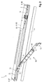
- FIG. 1 shows the locking assembly 1 in the normal state. It is in FIG. 1 only the housing 8 of the locking assembly 1, a reset switch 15 and a light-emitting element 16 to see. In this case, of the housing 8, an upper cover 82, a diaphragm 9 and opposite side parts 86, 87 are shown.
- the locking assembly 1 is used for attachment to a frame of a door, not shown. About the arm 6 shown, which is not part of the locking assembly 1, the connection to the door is done.
- FIG. 9 shows the housing 8 in perspective from a rear side, so that the aperture 9 is hidden.
- an additional element 83 connecting a lower cover 81 and the upper cover 82 is shown.
- the upper and the lower cover 81, 82 together with the additional element 83 is a monolithic base 80, which is designed as an H-carrier.
- the upper and lower covers 81, 82 may be surface-treated, for example painted, to form an outer surface of the locking assembly 1. Characterized in that an additional element 83 is present, the housing 8 has a high stability.
- the upper cover 81, the lower cover 82 and the auxiliary member 83 are variously broken.
- the upper and lower covers 81, 82 have passage openings 89 for a danger detector formed as a fire detector 14.
- openings 90, 91 for the reset switch 15 and the lighting means 16 are provided in the upper and lower covers 81, 82.
- the reset switch 15 and the lamp 16 protrude both on the lower and on the upper cover 81, 82 in the openings 90, 91. This allows mounting according to DIN right and DIN left possible.
- the reset switch 15 and the lighting means 16 are formed separately from the upper and lower covers 81, 82.
- the top cover 82 has a pre-perforated area 92.
- the lower cover 81 Prior to final assembly, the lower cover 81 also included a corresponding pre-perforated area. This was broken in the final assembly, with an opening 93 has formed in the lower cover 81.
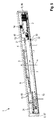
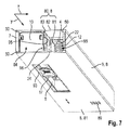
- the lower opening 93 serves to rotatably connect a sliding member 17 with the arm 6, so that the sliding member 17 when opening and closing the door leaf in a in the FIGS. 4 . 7 and 10 shown slide 5 is movable.
- the opening 93 is limited to the space required for the movement of the sliding member 17 in the slide rail 5.
- the lower cover 81 is continued behind the opening 93. As a result, the locking assembly 1 is particularly well protected.
- the upper and lower covers 81, 82 are mirror-symmetrical to each other.
- the side parts 86, 87 may be clipped in the openings 94. Likewise, the side parts 86, 87 are clipped in a mounting plate 7.
- the locking assembly 1 a locking device 10, in which the sliding member 17 can be fixed.
- the control unit 2 controls the locking device 10 in accordance with the release of the sliding member 17 after the control unit 2 has received a corresponding signal of the danger detector 14, in particular fire detector. This closes the door, not shown, z. B. by a door closer, not shown.
- the batteries 3 are in an energy storage package 60, which in FIG. 11 is shown arranged.
- both the locking device 10, the fire detector 14, the energy storage package 60, the slide 5 are arranged with the sliding member 17 and the control unit 2 in the housing 8.
- the upper cover 81 and the lower cover 82 are each designed monolithically seen in itself.
- the base 80 has a first receiving area 84 and a second receiving area 85.
- the first and the second receiving area 84, 85 are each a longitudinally open on one side rail.
- the first and second receiving areas 84, 85 each have projections 50.
- the mounting plate 7 is arranged and held by the projections 50 positively.
- the mounting plate 7 is used for arrangement on a frame of the door.
- the slide rail 5 with the sliding element 17, the locking device 10 and the control unit 2 are arranged on the mounting plate 7 and thus in the first receiving area 84. These elements 5, 10, 2 are thus arranged behind a rear side 96 of the additional element 83.
- the energy storage package 60 and the fire detector 14 are arranged.
- the batteries 3 and the fire detector 14 are arranged in front of the elements 5, 10, 2 of the locking arrangement 1 and at the same time in front of a front side 95 of the additional element 83.
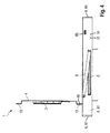
- the Figures 5 . 7 and 10 show an X and Y direction.
- the X direction is perpendicular to the plane of the door.
- the Y direction is perpendicular to the X direction.
- the slide rail 5, a holder 4 for the battery 3 and the battery 3 are arranged side by side in the X direction. In the Y-direction side by side are the slide 5 with the locking device 10 and the control unit 2. This arrangement is given a very compact design.
- the second receiving area 85 is covered by the aperture 9.
- the panel 9 is designed to be removable from the base body 80 and the side parts 86, 87. As a result, the fire detector 14 is serviced and the energy storage package 60 can be replaced without removing the main body 80 from the door.
- the aperture 9 is to be removed in order to reach the fire detector 14 and the energy storage package 60 immediately thereafter.
- the aperture 9 is made of plastic, glass or metal.
- the main body 80 is formed of metal.
- the side parts 86, 87 are formed of plastic.
- the side parts 86, 87 are clipped directly to the base body 80. In order to remove the panel 9 from the base body 80, one of the side parts 86, 87 can be removed. As a result, an operator can get behind the aperture 9 and push out the aperture 9 to the front.
- the panel 9 is arranged in the second receiving area 85 to the front of form-fitting. As a result, unfolding of the aperture 9 in case of fire is possible. Together with the panel 9, the energy storage package 60 works out.
- the energy storage package 60 is arranged on the holder 4.
- the holder 4 is rotatably arranged at a first end 41 of the holder 4 within the locking arrangement 1.
- a coil spring 12 is provided, which spring-loaded the holder 4.
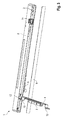
- the holder 4 via a trigger element 11 (s. FIG. 5 ) directly or indirectly connected to the mounting plate 7.
- the trigger element 11 is a plastic screw.
- the trigger element 11 is screwed to the mounting plate 7.
- the triggering element 10 has a head element 31, which rests against the holder 4 and whereby the holder 4 in a folded state, the in FIG. 5 is apparent, is held.
- the triggering element 10 is performed through an opening 47 through the holder 4.
- the trigger element 10 can remain in the opening 47 during unfolding and fold out with the holder 4.
- the holder 4 has a U-shaped form.
- connecting elements 13 are provided on connection zones 48 of the holder.
- These connecting elements 13 are, for example, adhesive pads, hook-and-loop fasteners or magnets.
- the diaphragm 9 is held on the holder 4.
- the holder 4 has a recess 43 which is disposed between the first end 41 and a battery holder 40. Through the recess 43, the heating of the battery 3 is delayed.
- the battery pack 60 is fixed in the battery holder 40 of the holder 4.
- battery receptacle 40 has opposite wall pieces 45.
- the wall pieces 45 are each provided with a passage 46, in which the energy storage package 60 attached to the batteries 3, in particular clipped, can, as in FIG. 2 shown.
- Between the wall pieces 45 is an opening 44 of the battery holder 40. Through the opening 44, the lateral concerns of the battery 3 is prevented on the holder 4.
- the energy storage package 60 includes spatially multiple successively arranged batteries 3, which form an energy storage device.
- batteries 3 are arranged one behind the other, whereby in each case two batteries are electrically connected in series, which in turn are connected in parallel to one another.
- a spring element 62 is arranged in each case, which can be clipped into the passages 46.
- the spring elements 62 and the batteries 3 are surrounded by a covering 61, from the connection cable 63 led out. Due to the compact design, the batteries 3 are replaceable very quickly.
- the insertion body 21 comprises the holder 4 and a pin 22 as an axis about which the first end 41 of the holder 4 is rotatable.
- the spring 12 is arranged around the pin.
- the pin 22 is attached to a slot holder 24.
- the insert holder 24 serves to be inserted into the second receiving area 85.
- the holder 4 can be arranged on the base body 80 via the insertion holder 24.
- the insert holder 24 and the fire detector 14 are initially arranged displaceably in the second receiving area 85 and can be fixed in the receiving area 85 during final assembly.
- the insert holder 24 may be opposite, in FIG. 8 include projections shown that receive the pin 22. Furthermore, the extensions are formed so long that the projections abut the projections 50 of the second receiving portion 85.
- the fire detector 14 is attached to the additional element 83.
- the energy storage package 60 is rotatably mounted on the holder 4 on the insertion holder 24.
- the insert holder 24 is attached via a screw 25 to the additional element 83.
- the screw 25 also serves to attach the additional element 83 and thus the entire body 80 to the slide rail 5 and / or on the mounting plate 7.
- the base body 80 is clipped both with the mounting plate 7 and screwed.
- a further screw 26 can be guided positively by an opening 49 of the holder.
- Fig. 12 an inventive method 100 is shown.
- the method 100 is divided into a pre-assembly according to the method steps 101 to 105 and into a final assembly according to the method steps 106 to 111.
- the method 100 is used for mounting in the FIGS. 1 to 11
- a first method step 101 the control unit 2, the slide rail 5 are mounted with the slider 17 and with the locking device 10 on the mounting plate 7, in particular screwed. This creates the first preassembled module.
- the insertion body 21 is composed of the insertion holder 24, the pin 22, intermediate elements 23, the spring 12 and the holder 4.
- the insertion body 21 is inserted into the base body 80.
- the insertion body 21 is slidably inserted in the second receiving area 85 of the base body 80.
- the holder 4 is transferred to the folded state and at the same time the spring 12 is tensioned, wherein a non-illustrated mounting fuse holds the holder 4 in the folded state.
- the fire detector 14 is inserted into the second receiving area 85. This creates a second preassembled module.
- the first and second assemblies may be assembled simultaneously or in any order sequentially.
- a sixth method step 106 the first preassembled module is fastened to the frame, in particular screwed.
- the second preassembled module is fastened to the first preassembled module, in particular clipped and / or screwed, inter alia, by the screws 25, 26.
- the batteries 3 are inserted into the holder 4 and the batteries 3 and the fire detector 14 are electrically connected to the control unit 2.
- side parts 86, 87 of the housing 8 are fastened to the base body 80, in particular clipped.
- the triggering element 11 is arranged on the holder 4 and screwed to the mounting plate 7.
- the mounting fuse is removed and the aperture 9 is fastened only to the holder 4.
- the method steps 108 to 110 may be in one be performed in any order. It is also conceivable to carry out method step 109 at the end.
Landscapes
- Engineering & Computer Science (AREA)
- Mechanical Engineering (AREA)
- Special Wing (AREA)
- Casings For Electric Apparatus (AREA)
Applications Claiming Priority (1)
| Application Number | Priority Date | Filing Date | Title |
|---|---|---|---|
| DE102015102923.5A DE102015102923A1 (de) | 2015-03-02 | 2015-03-02 | Feststellanordnung für eine Tür |
Publications (2)
| Publication Number | Publication Date |
|---|---|
| EP3064691A1 true EP3064691A1 (fr) | 2016-09-07 |
| EP3064691B1 EP3064691B1 (fr) | 2020-02-05 |
Family
ID=55027551
Family Applications (1)
| Application Number | Title | Priority Date | Filing Date |
|---|---|---|---|
| EP15203030.0A Active EP3064691B1 (fr) | 2015-03-02 | 2015-12-29 | Système de blocage de porte |
Country Status (2)
| Country | Link |
|---|---|
| EP (1) | EP3064691B1 (fr) |
| DE (1) | DE102015102923A1 (fr) |
Cited By (1)
| Publication number | Priority date | Publication date | Assignee | Title |
|---|---|---|---|---|
| DE102016015376C5 (de) | 2016-12-20 | 2021-11-25 | Wilh. Schlechtendahl & Söhne GmbH & Co. KG | Öffnungsbegrenzungseinrichtung sowie Rahmen-Flügel-Anordnung mit einer solchen |
Citations (3)
| Publication number | Priority date | Publication date | Assignee | Title |
|---|---|---|---|---|
| US4656690A (en) * | 1984-10-18 | 1987-04-14 | Ryobi Limited | Fireproof door closer and holder having a solenoid and a toggle mechanism |
| US4750236A (en) * | 1987-01-02 | 1988-06-14 | Yale Security Inc. | Track-type door hold-open device |
| EP1101893A2 (fr) * | 1999-11-20 | 2001-05-23 | GEZE GmbH | Dispositif de blocage pour ferme-porte, électroaimant et patin |
Family Cites Families (2)
| Publication number | Priority date | Publication date | Assignee | Title |
|---|---|---|---|---|
| US3926461A (en) * | 1974-08-01 | 1975-12-16 | Rixson Firemark | Electrically actuated door holder and release |
| DE8801896U1 (de) * | 1988-02-13 | 1988-03-24 | Gretsch-Unitas GmbH Baubeschläge, 7257 Ditzingen | Türschließer |
-
2015
- 2015-03-02 DE DE102015102923.5A patent/DE102015102923A1/de not_active Ceased
- 2015-12-29 EP EP15203030.0A patent/EP3064691B1/fr active Active
Patent Citations (3)
| Publication number | Priority date | Publication date | Assignee | Title |
|---|---|---|---|---|
| US4656690A (en) * | 1984-10-18 | 1987-04-14 | Ryobi Limited | Fireproof door closer and holder having a solenoid and a toggle mechanism |
| US4750236A (en) * | 1987-01-02 | 1988-06-14 | Yale Security Inc. | Track-type door hold-open device |
| EP1101893A2 (fr) * | 1999-11-20 | 2001-05-23 | GEZE GmbH | Dispositif de blocage pour ferme-porte, électroaimant et patin |
Cited By (1)
| Publication number | Priority date | Publication date | Assignee | Title |
|---|---|---|---|---|
| DE102016015376C5 (de) | 2016-12-20 | 2021-11-25 | Wilh. Schlechtendahl & Söhne GmbH & Co. KG | Öffnungsbegrenzungseinrichtung sowie Rahmen-Flügel-Anordnung mit einer solchen |
Also Published As
| Publication number | Publication date |
|---|---|
| EP3064691B1 (fr) | 2020-02-05 |
| DE102015102923A1 (de) | 2016-09-08 |
Similar Documents
| Publication | Publication Date | Title |
|---|---|---|
| DE102013113975B4 (de) | Halterahmen für einen Steckverbinder | |
| EP2339942B1 (fr) | Meuble avec tiroir et consommateur de courant | |
| DE102016105241B4 (de) | Fahrradbatteriehalterung und Fahrradbatterieeinheit | |
| WO2009062709A1 (fr) | Mécanisme d'entraînement pour porte | |
| EP2573874A2 (fr) | Connexion de conducteur | |
| EP3064688B1 (fr) | Systeme de blocage de porte | |
| EP2521233A2 (fr) | Pièce de montage pour inserts à montage en saillie, en encastrement et/ou en espace creux | |
| DE3628376C2 (fr) | ||
| EP3064691B1 (fr) | Système de blocage de porte | |
| EP2331783B1 (fr) | Boîtier pour la réception au moins partielle d'une ferrure de meuble | |
| EP2318791B1 (fr) | Sous-ensemble baguette de protection d'un appareil électro-ménager | |
| EP2582000B1 (fr) | Boîtier d'un appareil électrique ou électronique | |
| EP3064686A1 (fr) | Système de blocage | |
| EP2650608A2 (fr) | Dispositif d'alimentation électrique doté d'un corps de base auquel peuvent être fixés en différents endroits des adaptateurs, au moins un récepteur électrique pouvant être fixé au corps de base par au moins deux adaptateurs | |
| EP3396655A1 (fr) | Panneau led | |
| EP1921242A1 (fr) | Dispositif d'actionnement pour pièces mobiles de bâtiment, en particulier fenêtres ou trappes basculantes | |
| DE102013100822A1 (de) | Befestigungssystem und Einbausatz für die Montage eines Montagestegs in einem Schaltschrank | |
| EP3064690A1 (fr) | Agencement pour une porte | |
| DE3244643C2 (fr) | ||
| DE10005145A1 (de) | Sicherungseinsatz, insbesondere NH-Sicherungseinsatz | |
| EP3483374B1 (fr) | Rail de guidage permettant le guidage d'un battant de porte entre une position d'ouverture et une position de fermeture | |
| DE102021200495A1 (de) | Haushaltsgerät mit einer Kamera und positionsfixierter Anordnung eines Moduls in einem Gehäuseschacht der Kamera, sowie Verfahren | |
| DE19846219B4 (de) | Stromschalter | |
| DE29920244U1 (de) | Rolladen | |
| DE102013103594B4 (de) | Halteteil für eine Montageplatte, Türbetätiger-Anordnung und Verfahren zum Montieren einer Türbetätiger-Anordnung |
Legal Events
| Date | Code | Title | Description |
|---|---|---|---|
| PUAI | Public reference made under article 153(3) epc to a published international application that has entered the european phase |
Free format text: ORIGINAL CODE: 0009012 |
|
| AK | Designated contracting states |
Kind code of ref document: A1 Designated state(s): AL AT BE BG CH CY CZ DE DK EE ES FI FR GB GR HR HU IE IS IT LI LT LU LV MC MK MT NL NO PL PT RO RS SE SI SK SM TR |
|
| AX | Request for extension of the european patent |
Extension state: BA ME |
|
| STAA | Information on the status of an ep patent application or granted ep patent |
Free format text: STATUS: REQUEST FOR EXAMINATION WAS MADE |
|
| 17P | Request for examination filed |
Effective date: 20170223 |
|
| RBV | Designated contracting states (corrected) |
Designated state(s): AL AT BE BG CH CY CZ DE DK EE ES FI FR GB GR HR HU IE IS IT LI LT LU LV MC MK MT NL NO PL PT RO RS SE SI SK SM TR |
|
| RAP1 | Party data changed (applicant data changed or rights of an application transferred) |
Owner name: DORMAKABA DEUTSCHLAND GMBH |
|
| STAA | Information on the status of an ep patent application or granted ep patent |
Free format text: STATUS: EXAMINATION IS IN PROGRESS |
|
| 17Q | First examination report despatched |
Effective date: 20170915 |
|
| GRAP | Despatch of communication of intention to grant a patent |
Free format text: ORIGINAL CODE: EPIDOSNIGR1 |
|
| STAA | Information on the status of an ep patent application or granted ep patent |
Free format text: STATUS: GRANT OF PATENT IS INTENDED |
|
| INTG | Intention to grant announced |
Effective date: 20190802 |
|
| GRAS | Grant fee paid |
Free format text: ORIGINAL CODE: EPIDOSNIGR3 |
|
| GRAA | (expected) grant |
Free format text: ORIGINAL CODE: 0009210 |
|
| STAA | Information on the status of an ep patent application or granted ep patent |
Free format text: STATUS: THE PATENT HAS BEEN GRANTED |
|
| AK | Designated contracting states |
Kind code of ref document: B1 Designated state(s): AL AT BE BG CH CY CZ DE DK EE ES FI FR GB GR HR HU IE IS IT LI LT LU LV MC MK MT NL NO PL PT RO RS SE SI SK SM TR |
|
| REG | Reference to a national code |
Ref country code: GB Ref legal event code: FG4D Free format text: NOT ENGLISH |
|
| REG | Reference to a national code |
Ref country code: CH Ref legal event code: NV Representative=s name: FREI PATENTANWALTSBUERO AG, CH |
|
| REG | Reference to a national code |
Ref country code: AT Ref legal event code: REF Ref document number: 1230007 Country of ref document: AT Kind code of ref document: T Effective date: 20200215 |
|
| REG | Reference to a national code |
Ref country code: DE Ref legal event code: R096 Ref document number: 502015011635 Country of ref document: DE |
|
| REG | Reference to a national code |
Ref country code: IE Ref legal event code: FG4D Free format text: LANGUAGE OF EP DOCUMENT: GERMAN |
|
| REG | Reference to a national code |
Ref country code: CH Ref legal event code: EP |
|
| REG | Reference to a national code |
Ref country code: NL Ref legal event code: FP |
|
| PG25 | Lapsed in a contracting state [announced via postgrant information from national office to epo] |
Ref country code: PT Free format text: LAPSE BECAUSE OF FAILURE TO SUBMIT A TRANSLATION OF THE DESCRIPTION OR TO PAY THE FEE WITHIN THE PRESCRIBED TIME-LIMIT Effective date: 20200628 Ref country code: NO Free format text: LAPSE BECAUSE OF FAILURE TO SUBMIT A TRANSLATION OF THE DESCRIPTION OR TO PAY THE FEE WITHIN THE PRESCRIBED TIME-LIMIT Effective date: 20200505 Ref country code: RS Free format text: LAPSE BECAUSE OF FAILURE TO SUBMIT A TRANSLATION OF THE DESCRIPTION OR TO PAY THE FEE WITHIN THE PRESCRIBED TIME-LIMIT Effective date: 20200205 Ref country code: FI Free format text: LAPSE BECAUSE OF FAILURE TO SUBMIT A TRANSLATION OF THE DESCRIPTION OR TO PAY THE FEE WITHIN THE PRESCRIBED TIME-LIMIT Effective date: 20200205 |
|
| REG | Reference to a national code |
Ref country code: LT Ref legal event code: MG4D |
|
| PG25 | Lapsed in a contracting state [announced via postgrant information from national office to epo] |
Ref country code: HR Free format text: LAPSE BECAUSE OF FAILURE TO SUBMIT A TRANSLATION OF THE DESCRIPTION OR TO PAY THE FEE WITHIN THE PRESCRIBED TIME-LIMIT Effective date: 20200205 Ref country code: GR Free format text: LAPSE BECAUSE OF FAILURE TO SUBMIT A TRANSLATION OF THE DESCRIPTION OR TO PAY THE FEE WITHIN THE PRESCRIBED TIME-LIMIT Effective date: 20200506 Ref country code: SE Free format text: LAPSE BECAUSE OF FAILURE TO SUBMIT A TRANSLATION OF THE DESCRIPTION OR TO PAY THE FEE WITHIN THE PRESCRIBED TIME-LIMIT Effective date: 20200205 Ref country code: LV Free format text: LAPSE BECAUSE OF FAILURE TO SUBMIT A TRANSLATION OF THE DESCRIPTION OR TO PAY THE FEE WITHIN THE PRESCRIBED TIME-LIMIT Effective date: 20200205 Ref country code: BG Free format text: LAPSE BECAUSE OF FAILURE TO SUBMIT A TRANSLATION OF THE DESCRIPTION OR TO PAY THE FEE WITHIN THE PRESCRIBED TIME-LIMIT Effective date: 20200505 Ref country code: IS Free format text: LAPSE BECAUSE OF FAILURE TO SUBMIT A TRANSLATION OF THE DESCRIPTION OR TO PAY THE FEE WITHIN THE PRESCRIBED TIME-LIMIT Effective date: 20200605 |
|
| PG25 | Lapsed in a contracting state [announced via postgrant information from national office to epo] |
Ref country code: ES Free format text: LAPSE BECAUSE OF FAILURE TO SUBMIT A TRANSLATION OF THE DESCRIPTION OR TO PAY THE FEE WITHIN THE PRESCRIBED TIME-LIMIT Effective date: 20200205 Ref country code: CZ Free format text: LAPSE BECAUSE OF FAILURE TO SUBMIT A TRANSLATION OF THE DESCRIPTION OR TO PAY THE FEE WITHIN THE PRESCRIBED TIME-LIMIT Effective date: 20200205 Ref country code: LT Free format text: LAPSE BECAUSE OF FAILURE TO SUBMIT A TRANSLATION OF THE DESCRIPTION OR TO PAY THE FEE WITHIN THE PRESCRIBED TIME-LIMIT Effective date: 20200205 Ref country code: SM Free format text: LAPSE BECAUSE OF FAILURE TO SUBMIT A TRANSLATION OF THE DESCRIPTION OR TO PAY THE FEE WITHIN THE PRESCRIBED TIME-LIMIT Effective date: 20200205 Ref country code: RO Free format text: LAPSE BECAUSE OF FAILURE TO SUBMIT A TRANSLATION OF THE DESCRIPTION OR TO PAY THE FEE WITHIN THE PRESCRIBED TIME-LIMIT Effective date: 20200205 Ref country code: SK Free format text: LAPSE BECAUSE OF FAILURE TO SUBMIT A TRANSLATION OF THE DESCRIPTION OR TO PAY THE FEE WITHIN THE PRESCRIBED TIME-LIMIT Effective date: 20200205 Ref country code: DK Free format text: LAPSE BECAUSE OF FAILURE TO SUBMIT A TRANSLATION OF THE DESCRIPTION OR TO PAY THE FEE WITHIN THE PRESCRIBED TIME-LIMIT Effective date: 20200205 Ref country code: EE Free format text: LAPSE BECAUSE OF FAILURE TO SUBMIT A TRANSLATION OF THE DESCRIPTION OR TO PAY THE FEE WITHIN THE PRESCRIBED TIME-LIMIT Effective date: 20200205 |
|
| REG | Reference to a national code |
Ref country code: DE Ref legal event code: R097 Ref document number: 502015011635 Country of ref document: DE |
|
| PLBE | No opposition filed within time limit |
Free format text: ORIGINAL CODE: 0009261 |
|
| STAA | Information on the status of an ep patent application or granted ep patent |
Free format text: STATUS: NO OPPOSITION FILED WITHIN TIME LIMIT |
|
| 26N | No opposition filed |
Effective date: 20201106 |
|
| PG25 | Lapsed in a contracting state [announced via postgrant information from national office to epo] |
Ref country code: IT Free format text: LAPSE BECAUSE OF FAILURE TO SUBMIT A TRANSLATION OF THE DESCRIPTION OR TO PAY THE FEE WITHIN THE PRESCRIBED TIME-LIMIT Effective date: 20200205 |
|
| PG25 | Lapsed in a contracting state [announced via postgrant information from national office to epo] |
Ref country code: PL Free format text: LAPSE BECAUSE OF FAILURE TO SUBMIT A TRANSLATION OF THE DESCRIPTION OR TO PAY THE FEE WITHIN THE PRESCRIBED TIME-LIMIT Effective date: 20200205 Ref country code: SI Free format text: LAPSE BECAUSE OF FAILURE TO SUBMIT A TRANSLATION OF THE DESCRIPTION OR TO PAY THE FEE WITHIN THE PRESCRIBED TIME-LIMIT Effective date: 20200205 |
|
| GBPC | Gb: european patent ceased through non-payment of renewal fee |
Effective date: 20201229 |
|
| PG25 | Lapsed in a contracting state [announced via postgrant information from national office to epo] |
Ref country code: MC Free format text: LAPSE BECAUSE OF FAILURE TO SUBMIT A TRANSLATION OF THE DESCRIPTION OR TO PAY THE FEE WITHIN THE PRESCRIBED TIME-LIMIT Effective date: 20200205 |
|
| REG | Reference to a national code |
Ref country code: BE Ref legal event code: MM Effective date: 20201231 |
|
| PG25 | Lapsed in a contracting state [announced via postgrant information from national office to epo] |
Ref country code: IE Free format text: LAPSE BECAUSE OF NON-PAYMENT OF DUE FEES Effective date: 20201229 Ref country code: LU Free format text: LAPSE BECAUSE OF NON-PAYMENT OF DUE FEES Effective date: 20201229 |
|
| PG25 | Lapsed in a contracting state [announced via postgrant information from national office to epo] |
Ref country code: GB Free format text: LAPSE BECAUSE OF NON-PAYMENT OF DUE FEES Effective date: 20201229 |
|
| PG25 | Lapsed in a contracting state [announced via postgrant information from national office to epo] |
Ref country code: TR Free format text: LAPSE BECAUSE OF FAILURE TO SUBMIT A TRANSLATION OF THE DESCRIPTION OR TO PAY THE FEE WITHIN THE PRESCRIBED TIME-LIMIT Effective date: 20200205 Ref country code: MT Free format text: LAPSE BECAUSE OF FAILURE TO SUBMIT A TRANSLATION OF THE DESCRIPTION OR TO PAY THE FEE WITHIN THE PRESCRIBED TIME-LIMIT Effective date: 20200205 Ref country code: CY Free format text: LAPSE BECAUSE OF FAILURE TO SUBMIT A TRANSLATION OF THE DESCRIPTION OR TO PAY THE FEE WITHIN THE PRESCRIBED TIME-LIMIT Effective date: 20200205 |
|
| PG25 | Lapsed in a contracting state [announced via postgrant information from national office to epo] |
Ref country code: MK Free format text: LAPSE BECAUSE OF FAILURE TO SUBMIT A TRANSLATION OF THE DESCRIPTION OR TO PAY THE FEE WITHIN THE PRESCRIBED TIME-LIMIT Effective date: 20200205 Ref country code: AL Free format text: LAPSE BECAUSE OF FAILURE TO SUBMIT A TRANSLATION OF THE DESCRIPTION OR TO PAY THE FEE WITHIN THE PRESCRIBED TIME-LIMIT Effective date: 20200205 |
|
| PG25 | Lapsed in a contracting state [announced via postgrant information from national office to epo] |
Ref country code: BE Free format text: LAPSE BECAUSE OF NON-PAYMENT OF DUE FEES Effective date: 20201231 |
|
| REG | Reference to a national code |
Ref country code: CH Ref legal event code: U11 Free format text: ST27 STATUS EVENT CODE: U-0-0-U10-U11 (AS PROVIDED BY THE NATIONAL OFFICE) Effective date: 20260101 |
|
| PGFP | Annual fee paid to national office [announced via postgrant information from national office to epo] |
Ref country code: DE Payment date: 20251211 Year of fee payment: 11 |
|
| PGFP | Annual fee paid to national office [announced via postgrant information from national office to epo] |
Ref country code: AT Payment date: 20251222 Year of fee payment: 11 |
|
| PGFP | Annual fee paid to national office [announced via postgrant information from national office to epo] |
Ref country code: FR Payment date: 20251223 Year of fee payment: 11 Ref country code: NL Payment date: 20251219 Year of fee payment: 11 |
|
| PGFP | Annual fee paid to national office [announced via postgrant information from national office to epo] |
Ref country code: CH Payment date: 20260101 Year of fee payment: 11 |