EP3064697A1 - Moyen d'espacement pour un composant de construction - Google Patents
Moyen d'espacement pour un composant de construction Download PDFInfo
- Publication number
- EP3064697A1 EP3064697A1 EP16159055.9A EP16159055A EP3064697A1 EP 3064697 A1 EP3064697 A1 EP 3064697A1 EP 16159055 A EP16159055 A EP 16159055A EP 3064697 A1 EP3064697 A1 EP 3064697A1
- Authority
- EP
- European Patent Office
- Prior art keywords
- spacing means
- spacing
- building component
- support member
- spacer
- Prior art date
- Legal status (The legal status is an assumption and is not a legal conclusion. Google has not performed a legal analysis and makes no representation as to the accuracy of the status listed.)
- Withdrawn
Links
Images

Classifications
-
- E—FIXED CONSTRUCTIONS
- E06—DOORS, WINDOWS, SHUTTERS, OR ROLLER BLINDS IN GENERAL; LADDERS
- E06B—FIXED OR MOVABLE CLOSURES FOR OPENINGS IN BUILDINGS, VEHICLES, FENCES OR LIKE ENCLOSURES IN GENERAL, e.g. DOORS, WINDOWS, BLINDS, GATES
- E06B1/00—Border constructions of openings in walls, floors, or ceilings; Frames to be rigidly mounted in such openings
- E06B1/56—Fastening frames to the border of openings or to similar contiguous frames
- E06B1/60—Fastening frames to the border of openings or to similar contiguous frames by mechanical means, e.g. anchoring means
- E06B1/6069—Separate spacer means acting exclusively in the plane of the opening; Shims; Wedges; Tightening of a complete frame inside a wall opening
Definitions
- the present invention relates to a spacing means and in particular to a spacing means for a building component.
- a lintel is often used. While structurally the lintel solves the issue of carrying the weight of the masonry directly above the opening, masonry supports are often utilised which allow attachment of masonry on one or both sides, namely fascia or soffit of the lintel so that a consistent appearance with the adjacent masonry can be achieved.
- Masonry supports are typically in the form of metallic brackets and bracket spanning components. As a result of the rigid metallic construction, masonry supports are typically restricted with respect to the width of cavity which can be accommodated thereby. Spacers are employed to pack out the rear of masonry support brackets, increasing the space between the surface and the brackets attachable thereto, and therefore adjusting the size of the cavity created.
- the surface of the structural support to which the bracket or other intermediate fixing members are to be attached to are often not perfectly plumb or level, vertically. This means that if a spacer with a uniform thickness along the length and width of the spacer is used, the off level plane is transferred through the spacer into the masonry support bracket and on to the masonry façade support by the masonry support.
- the typically metallic masonry support provides a cold bridge capable of transferring cold from the exterior into the cavity and beyond, resulting in a lower overall building thermal efficiency.
- cold bridging elements such as masonry support brackets
- the present invention provides a spacing means for insertion between a support surface of a structural support member and a mutually opposing support surface of a mounting means of a building component mountable on the support surface of the structural support member, the spacing means having compensation means for setting a non-parallel planar relationship between the support surface of the structural support member and the mutually opposing support surface of the mounting means of the building component.
- one or more spacing means with compensation means can be utilised to compensate for the non-level surface of the structural support member.
- one or more spacing means with compensation means can be utilised to set at least part of the building component off the level or plumb in an unloaded condition.
- brick slips are often attached to the underside/soffit of a masonry support member for aesthetic continuity.
- the brick slip support is subsequently loaded with brick and this downward load of the bricks will cause a slight flex on the masonry support altering the angle of inclination of the soffit portion of the masonry support. If the soffit is initially set to be inclined upwardly at approximately the same angle of flex caused by downward moment of the bricks, the soffit will appear level in the loaded condition.
- the compensating means of the spacing means compensates for off plumb or off level support surfaces where the off plumb/off level support surface has to be converted to a level surface for at least part of the building component.
- the compensating means provides the technical functionality for producing an off plum or off level façade surface for the building component when the building component is mounted on a plumb/level support surface of the structural support component.
- the compensation means for setting a non-parallel planar relationship between the support surface of the structural support member and the mutually opposing support surface of the mounting means of the building component can be adapted to set a range of inclined angles from 1 to 4 degrees, most preferably 1.5 degrees.
- the building component is mounted to the support surface of the structural support member by intermediate mounting means.
- the intermediate mounting means are separable from the building component.
- the mutually opposing support surface is the surface of the intermediate mounting means normally mounted on the structural support member.
- the intermediate mounting means is a bracket.
- the building component is a masonry support.
- the masonry support is a welded masonry support, a brick slip support, a loose bracket and shelf or any such masonry support wherein a bracket or similar intermediate mounting means is utilized to support a masonry component.
- the spacing means is similar in dimension to the surface of the mounting means typically contactable with the structural support member.
- the spacing means is a generally quadrangular spacing means having two longitudinal edges joined by two lateral edges.
- the spacing means has a non-uniform thickness along the body of the spacing means.
- the spacing means has a reducing thickness between two opposite ends of the spacing means.
- the spacing means has a reducing thickness along its longitudinal or lateral length.
- the rate of the reducing thickness is constant along the length or between the ends of the spacing means.
- the spacing means has a reducing thickness from an upper end to a lower end or vice versa in use.
- the spacing means has a wedge shape.
- the spacing means tapers from a thick end to a thin end.
- the rate of the taper is constant along the length or between the ends of the spacing means.
- the thick end has a thickness in a range of between 4-8 mm and the thin end has a thickness in the range of between 1-4 mm.
- the length of the spacing means is in the range of between 100 mm and 300 mm, most preferably 150 mm and 250 mm.
- the width of the spacing means is a range of between 20 -50 mm.
- the surface of the spacing means is uneven.
- this reduces slippage between the shim and components which are in contact with these uneven surfaces.
- the surface of the spacing means is ribbed.
- the surface of the spacing means which is uneven is the two main planar surfaces which will be in contact with the surface of the structural support member and the mutually opposing surface of the building component or with an adjacent spacing means.
- the spacing means comprising means for suspending the spacing means in a pre-determined orientation from a portion of the building component or a fixture thereof.
- the suspension means having at least one suspending portion for suspending the spacing means from the building component or a fixture thereof and movement restriction means depending downwardly from the suspension portion on both sides of the suspension portion so as to be locatable around both sides of the portion of the building component or mounting means thereof.
- means for suspending the spacing means comprises an aperture within the body of the spacing means.
- the means for suspending the spacing means being formed for only partially enclosing a portion of the building component or mounting means thereof.
- the means for suspending the spacing means in a pre-determined orientation comprises an elongate slot extending longitudinally from and through one end of the spacing means proximal to the other end of the spacing means.
- the means for suspending the spacing means in a pre-determined orientation comprises an elongate slot extending longitudinally from and through one longitudinal end of the spacing means proximal to the other longitudinal end of the spacing means.
- the elongate slot has means for reducing the width of the elongate slot gap.
- the means for reducing the width of the elongate slot gap are provided on one both sides of the slot.
- the means for reducing the width of the elongate slot gap is one or more nibs protruding into the space of the slot.
- the nibs are provided on mutually opposing locations of the slot.
- the means for reducing the width of the gap of the elongate slot provide two functions. In the event that the spacing means is accidentally knocked and caused to rotate through 180 degrees it will catch on the width reducing means preventing the spacing means from falling off the support/mounting member.
- the spacers are often being installed at a height and so this prevent the spacers falling from a height and having to be retrieved or worse causing a health hazard as a falling object.
- the width reducing means provide two upright mounting positions for the spacing means upside down from each other.
- the width reducing means reduces the width of the gap of the slot to cause an interference fit between the width reducing means and the generally horizontal support member such as a bolt along which the spacing means is generally sliding into position.
- the width reducing means causing sufficient resistance to the travel of the bolt or other support member so as to prevent the spacing means being capable of moving past the bolt under its own weight.
- an operator can readily overcome the interference fit by manually applying pressure to push the spacing means onto or to pull the spacing means off the bolt.
- the spacing means is a plate.
- the spacing means is a shim or packer.
- the spacing means has an opening for receiving the portion of or fixture of the building component.
- the spacing means comprising means for suspending the spacing means in a pre-determined orientation from a portion of the building component or a fixture thereof, the suspension means having at least one suspending portion for suspending the spacing means from the building component or a fixture thereof and movement restriction means depending downwardly from the suspension portion on both sides of the suspension portion so as to be locatable around both sides of the portion of the building component or fixture thereof, the portion of the building component or fixture thereof being at least partially enclosable by the movement restriction means.
- the movement restriction means prevents the spacer means sliding laterally off the portion of the building component or fixture thereof in the event of the spacing means receiving unintended contact during installation.
- the suspension means is a hook.
- the suspension means being configured so that the spacing means is only removable from the building component by at least upward movement of the spacing means.
- the suspension means being configured so that the spacing means is only removable from the building component by a combination of upward movement and lateral movement of the spacing means.
- the suspension means being configured so that the center of gravity of the spacing means must be raised above the suspension portion for the spacing means to be removed from the building component as a result of rotation.
- the spacing means is a plate.
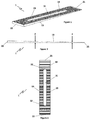
- the spacer 1 having a compensation arrangement 2 for setting a non-parallel planar relationship between the support surface of the structural support member and the mutually opposing support surface of the mounting bracket of the building component.
- one or more spacers 1 with compensation arrangements 2 can be utilised to compensate for the non-level surface of the structural support member.
- one or more spacers 1 with compensation arrangements 2 can be utilised to set at least part of the building component off the level in an unloaded condition.
- this initial off level mounting may be useful, brick slips are often attached to the underside/soffit of a masonry support member for aesthetic continuity.
- the brick slip support member is subsequently loaded with brick and this downward load of the bricks will cause a slight flex on the masonry support member altering the angle of inclination of the soffit portion of the masonry support member. If the soffit is initially set to be inclined upwardly at approximately the same angle of flex caused by downward moment of the bricks, the soffit will appear level in the loaded condition.
- the compensating arrangement 2 of the spacer 1 compensates for off plumb or off level support surfaces where the off plumb/level support surface has to be converted to a level surface for at least part of the building component.
- the compensating arrangement 2 provides the technical functionality for producing an off plum or off level façade surface for the building component when the building component is mounted on a plumb/level support surface of the structural support component.
- the building component is mounted to the support surface of the structural support member by intermediate mounting members provided by wall mounting brackets and a nut and bolt and washer assembly.
- the intermediate mounting members have a planar surface formed for sitting flush with the planar surface of the wall or now with this invention with the planar surface of the spacer 1.
- the intermediate mounting members are separable from the building component.
- the mutually opposing support surface is the surface of the mounting bracket normally mounted on the structural support member.
- the building component is a masonry support.
- the masonry support is a welded masonry support, a brick slip support, a bracket and shelf or any such masonry support wherein a bracket or similar intermediate mounting arrangement is utilized to support a masonry component.
- the main planar surfaces 18 of spacer 1 have similar length and width dimensions to the surface 14 of the mounting bracket typically mounted with the structural support member.
- the spacer 1 is a generally quadrangular body having two longitudinal edges 19 joined by two lateral edges 21, 22.
- the spacer 1 has a non-uniform thickness along the body of the spacer 1.
- the spacer 1 has a reducing thickness between two opposite ends 21, 22 thereof.
- the spacer 1 has a reducing thickness along its longitudinal length. The rate of the reducing thickness is constant along the length or between the ends of the spacer 1.
- the spacer 1 When mounted as illustrated in Figures 3 , the spacer 1 has a reducing thickness from an upper end to a lower end or vice versa in use.
- the spacer 1 has a wedge shape.
- the spacer 1 tapers from a thick end 22 to a thin end 21.
- the rate of the taper is constant along the length or between the ends 21, 22 of the spacer 1.
- the thick end 22 has a thickness in a range of between 5-7 mm and the thin end 21 has a thickness in the range of between 1-3 mm.
- the length of the spacer is in the range of between 150 and 250 mm.
- the width of the spacer 1 is a range of between 20 -50 mm.
- the surface 18 of the spacer 1 is uneven. Advantageously, this reduces slippage between the spacer/shim 1 and components which are in contact with these uneven surfaces 18.
- the surfaces 18 of the spacer illustrated are ribbed.
- the ribbed surfaces 18 allow for greater grip between the spacer 1 and the surface contactable with the ribbed surface 18.
- the ribs extend transverse the spacer generally perpendicular to the longitudinal axis of the spacer.
- the surfaces 18 of the spacer 1 which are uneven is the two main planar surfaces 18 which will be in contact with the surface 12 of the structural support member 13 and the mutually opposing surface 14 of the mounting bracket 5 of the building component 15 or with an adjacent spacer 1.
- the spacer 1 is manufactured from a material capable of resisting compressive loading.
- the loads acting on the building component can be in the range of 6 to 16 kn/m.
- the spacer material is a material capable of reducing thermal bridging.
- the spacer material is a material is also capable of preventing bi-metallic corrosion and/or galvanic corrosion.
- the spacer material is preferably nylon.
- the spacers are moulded to allow accuracy of the taper angle and to ensure reproducibility of a consistent taper angle.
- the spacer is designed to transfer the load between the support structure and the building component and/or bracket thereof evenly along the length of the building component and/or bracket.
- the spacer is rotatable through 180 degrees to allow for the spacer to work upside down. This allows the spacer to compensate for a surface with various types of surface inclines off plumb such as where the surface is inclined forward from the vertical or where the surface is inclined backwards from the vertical.
- the spacer 1 illustrated in Figures 1 to 3 has an aperture 31 for suspending the spacer in a pre-determined orientation from a portion of the building component 15 or a fixture 3 thereof.
- the suspension aperture 31 has a suspending portion 32 for suspending the spacer 1 from the building component 15 or a fixture 3 thereof and a movement restriction arrangement being the sides of the aperture 31 depending downwardly from the suspension portion 32 in use.
- the aperture 31 allows the spacer 1 to be turned upside down to allow the taper to work in both directions.
- FIG. 4 and 5 of the drawings there is shown a second embodiment of a spacer for a masonry support indicated generally by the reference numeral 41.
- the arrangement for suspending the spacer in a pre-determined orientation comprises an elongate slot 42 extending longitudinally from and through one lateral end 43 of the spacer proximal to the other lateral end 44 of the spacer 41.
- the elongate slot 42 has an arrangement 45 for reducing the width of the elongate slot.
- the arrangement 45 for reducing the width of the elongate slot 42 are provided on both sides of the slot 42.
- the arrangement 45 for reducing the width of the elongate slot 42 is two nibs 45 protruding into the space of the slot 42 provided on mutually opposing locations of the slot 42.
- the slot 42 extends along the length of the spacer 41 to allow for the vertical movement of the shim to suit the slope in the support structure.
- the arrangement 45 for reducing the width of the gap of the elongate slot 42 provides two functions. In the event that the spacer 41 is accidentally knocked and caused to rotate through 180 degrees it will catch on the width reducing arrangement 45 preventing the spacer from falling off the support/mounting member. The spacers 41 are often being installed at a height and so this prevent the spacers 41 falling from a height and having to be retrieved or worse causing a health hazard as a falling object. Secondly, the width reducing arrangement 45 provide two upright mounting positions for the spacer 41 upside down from each other.
- the width reducing arrangement 45 reduces the width of the gap of the slot 42 to cause an interference fit between the width reducing arrangement 45 and the generally horizontal support member such as a bolt along which the spacer is generally sliding into position.
- the width reducing arrangement 45 causing sufficient resistance to the travel of the bolt or other support member so as to prevent the spacer being capable of moving past the bolt under its own weight.
- an operator can readily overcome the interference fit by manually applying pressure to push the spacer onto or to pull the spacing means off the bolt.
Landscapes
- Engineering & Computer Science (AREA)
- Mechanical Engineering (AREA)
- Civil Engineering (AREA)
- Structural Engineering (AREA)
- Building Environments (AREA)
Applications Claiming Priority (1)
| Application Number | Priority Date | Filing Date | Title |
|---|---|---|---|
| GB201503860A GB201503860D0 (en) | 2015-03-06 | 2015-03-06 | A spacing means for a building component |
Publications (1)
| Publication Number | Publication Date |
|---|---|
| EP3064697A1 true EP3064697A1 (fr) | 2016-09-07 |
Family
ID=52998539
Family Applications (1)
| Application Number | Title | Priority Date | Filing Date |
|---|---|---|---|
| EP16159055.9A Withdrawn EP3064697A1 (fr) | 2015-03-06 | 2016-03-07 | Moyen d'espacement pour un composant de construction |
Country Status (2)
| Country | Link |
|---|---|
| EP (1) | EP3064697A1 (fr) |
| GB (1) | GB201503860D0 (fr) |
Citations (5)
| Publication number | Priority date | Publication date | Assignee | Title |
|---|---|---|---|---|
| EP0171545A1 (fr) * | 1984-07-12 | 1986-02-19 | Hans-Dieter Niemann | Coin d'ajustage pour combler un intervalle dans le bâtiment |
| FR2625244A1 (fr) * | 1987-12-24 | 1989-06-30 | Bonnivard Guy | Dispositif de calage pour mise a niveau de plancher, plafond, paroi ou panneau |
| EP0719953A2 (fr) * | 1994-12-31 | 1996-07-03 | Wolfgang Rathsack | Dispositif de mise à niveau pour éléments de construction |
| FR2846362A1 (fr) * | 2002-10-25 | 2004-04-30 | Goettgens Henri | Plaquette pour le calage en position d 'un chassis dans une baie de batiment. |
| US7716880B1 (en) * | 2001-08-14 | 2010-05-18 | Teton West Lumber, Inc. | Composite products and methods of producing same |
-
2015
- 2015-03-06 GB GB201503860A patent/GB201503860D0/en not_active Ceased
-
2016
- 2016-03-07 EP EP16159055.9A patent/EP3064697A1/fr not_active Withdrawn
Patent Citations (5)
| Publication number | Priority date | Publication date | Assignee | Title |
|---|---|---|---|---|
| EP0171545A1 (fr) * | 1984-07-12 | 1986-02-19 | Hans-Dieter Niemann | Coin d'ajustage pour combler un intervalle dans le bâtiment |
| FR2625244A1 (fr) * | 1987-12-24 | 1989-06-30 | Bonnivard Guy | Dispositif de calage pour mise a niveau de plancher, plafond, paroi ou panneau |
| EP0719953A2 (fr) * | 1994-12-31 | 1996-07-03 | Wolfgang Rathsack | Dispositif de mise à niveau pour éléments de construction |
| US7716880B1 (en) * | 2001-08-14 | 2010-05-18 | Teton West Lumber, Inc. | Composite products and methods of producing same |
| FR2846362A1 (fr) * | 2002-10-25 | 2004-04-30 | Goettgens Henri | Plaquette pour le calage en position d 'un chassis dans une baie de batiment. |
Also Published As
| Publication number | Publication date |
|---|---|
| GB201503860D0 (en) | 2015-04-22 |
Similar Documents
| Publication | Publication Date | Title |
|---|---|---|
| KR200452381Y1 (ko) | 건축물의 외장재 고정장치 | |
| CA2705995C (fr) | Stabilisateur d'echelle perfectionne | |
| KR20130045711A (ko) | 실내장식용 커튼월 시공장치 | |
| CN211647401U (zh) | 一种适合多工况建筑墙体支撑结构 | |
| WO2009040572A2 (fr) | Aide au briquetage | |
| RU166750U1 (ru) | Консоль кронштейна навесной конструкции | |
| KR102574951B1 (ko) | 개구를 가지는 조적 벽체용 보강 구조 | |
| JP2010106434A (ja) | 吊り戸装置 | |
| CN216340293U (zh) | 一种外层幕墙为uhpc材质的双层幕墙系统 | |
| JP2014169573A (ja) | 天井吊り金具及び天井下地材支持構造 | |
| EP2666918B1 (fr) | Balcon | |
| GB2506656A (en) | Masonry support attachment | |
| CN113622569A (zh) | 一种外层幕墙为uhpc材质的双层幕墙系统 | |
| KR101072091B1 (ko) | 창호 시공 시 가틀의 수평 조절작업을 위한 조절부재 | |
| KR20110000380U (ko) | 벽 판넬의 높은 베이스 | |
| WO2017048144A1 (fr) | Profilé pour un système de fixation et d'isolation thermique de fenêtres, portes et façades | |
| EP1640526A2 (fr) | Dispositif pour le montage d'une marquise | |
| KR200497116Y1 (ko) | 무해체 거푸집용 철근 안전고정장치 | |
| KR100676840B1 (ko) | 높이 조절가능한 온돌바닥구조 | |
| KR100943094B1 (ko) | 발코니 확장용 창호 하부지지부재 및 이를 이용한 발코니확장용 창호 시공방법 | |
| CN203286135U (zh) | 楼层间竖向桥架内腔防火封堵托盘 | |
| CN211341337U (zh) | 一种墙砖用轨道式安装结构 | |
| CN209758269U (zh) | 一种电熔锆刚玉砖输送用可调方向的输送带 | |
| JP2008095463A (ja) | 建築用鉛直調整器 | |
| GB2485147A (en) | A support for loads such as masonry |
Legal Events
| Date | Code | Title | Description |
|---|---|---|---|
| PUAI | Public reference made under article 153(3) epc to a published international application that has entered the european phase |
Free format text: ORIGINAL CODE: 0009012 |
|
| AK | Designated contracting states |
Kind code of ref document: A1 Designated state(s): AL AT BE BG CH CY CZ DE DK EE ES FI FR GB GR HR HU IE IS IT LI LT LU LV MC MK MT NL NO PL PT RO RS SE SI SK SM TR |
|
| AX | Request for extension of the european patent |
Extension state: BA ME |
|
| RIN1 | Information on inventor provided before grant (corrected) |
Inventor name: COYLE, OWEN |
|
| STAA | Information on the status of an ep patent application or granted ep patent |
Free format text: STATUS: REQUEST FOR EXAMINATION WAS MADE |
|
| 17P | Request for examination filed |
Effective date: 20170307 |
|
| RBV | Designated contracting states (corrected) |
Designated state(s): AL AT BE BG CH CY CZ DE DK EE ES FI FR GB GR HR HU IE IS IT LI LT LU LV MC MK MT NL NO PL PT RO RS SE SI SK SM TR |
|
| STAA | Information on the status of an ep patent application or granted ep patent |
Free format text: STATUS: EXAMINATION IS IN PROGRESS |
|
| 17Q | First examination report despatched |
Effective date: 20191119 |
|
| STAA | Information on the status of an ep patent application or granted ep patent |
Free format text: STATUS: THE APPLICATION IS DEEMED TO BE WITHDRAWN |
|
| 18D | Application deemed to be withdrawn |
Effective date: 20221001 |