EP3064714A1 - Profil, aube rotorique et procédés associés - Google Patents
Profil, aube rotorique et procédés associés Download PDFInfo
- Publication number
- EP3064714A1 EP3064714A1 EP16158425.5A EP16158425A EP3064714A1 EP 3064714 A1 EP3064714 A1 EP 3064714A1 EP 16158425 A EP16158425 A EP 16158425A EP 3064714 A1 EP3064714 A1 EP 3064714A1
- Authority
- EP
- European Patent Office
- Prior art keywords
- airfoil
- tip
- divider
- squealer
- Prior art date
- Legal status (The legal status is an assumption and is not a legal conclusion. Google has not performed a legal analysis and makes no representation as to the accuracy of the status listed.)
- Withdrawn
Links
- 238000000034 method Methods 0.000 title claims description 16
- 238000001816 cooling Methods 0.000 claims abstract description 52
- 239000012530 fluid Substances 0.000 claims abstract description 47
- 238000004891 communication Methods 0.000 claims abstract description 19
- 230000003068 static effect Effects 0.000 claims description 10
- 230000000903 blocking effect Effects 0.000 claims description 6
- 239000007789 gas Substances 0.000 description 8
- 238000000576 coating method Methods 0.000 description 6
- 230000008901 benefit Effects 0.000 description 4
- 239000011248 coating agent Substances 0.000 description 4
- 230000037361 pathway Effects 0.000 description 4
- 238000011144 upstream manufacturing Methods 0.000 description 4
- 229910000951 Aluminide Inorganic materials 0.000 description 3
- 238000012986 modification Methods 0.000 description 3
- 230000004048 modification Effects 0.000 description 3
- 125000006850 spacer group Chemical group 0.000 description 3
- 230000008859 change Effects 0.000 description 2
- 239000000567 combustion gas Substances 0.000 description 2
- 238000005260 corrosion Methods 0.000 description 2
- 230000007797 corrosion Effects 0.000 description 2
- 229920006395 saturated elastomer Polymers 0.000 description 2
- 230000004075 alteration Effects 0.000 description 1
- XAGFODPZIPBFFR-UHFFFAOYSA-N aluminium Chemical compound [Al] XAGFODPZIPBFFR-UHFFFAOYSA-N 0.000 description 1
- 229910052782 aluminium Inorganic materials 0.000 description 1
- 238000005266 casting Methods 0.000 description 1
- 239000012809 cooling fluid Substances 0.000 description 1
- 230000002708 enhancing effect Effects 0.000 description 1
- 238000000605 extraction Methods 0.000 description 1
- 239000003112 inhibitor Substances 0.000 description 1
- 238000009434 installation Methods 0.000 description 1
- 230000003993 interaction Effects 0.000 description 1
- 230000008569 process Effects 0.000 description 1
- -1 steam Substances 0.000 description 1
- 238000006467 substitution reaction Methods 0.000 description 1
Images


Classifications
-
- F—MECHANICAL ENGINEERING; LIGHTING; HEATING; WEAPONS; BLASTING
- F01—MACHINES OR ENGINES IN GENERAL; ENGINE PLANTS IN GENERAL; STEAM ENGINES
- F01D—NON-POSITIVE DISPLACEMENT MACHINES OR ENGINES, e.g. STEAM TURBINES
- F01D5/00—Blades; Blade-carrying members; Heating, heat-insulating, cooling or antivibration means on the blades or the members
- F01D5/12—Blades
- F01D5/14—Form or construction
- F01D5/18—Hollow blades, i.e. blades with cooling or heating channels or cavities; Heating, heat-insulating or cooling means on blades
- F01D5/186—Film cooling
-
- F—MECHANICAL ENGINEERING; LIGHTING; HEATING; WEAPONS; BLASTING
- F01—MACHINES OR ENGINES IN GENERAL; ENGINE PLANTS IN GENERAL; STEAM ENGINES
- F01D—NON-POSITIVE DISPLACEMENT MACHINES OR ENGINES, e.g. STEAM TURBINES
- F01D5/00—Blades; Blade-carrying members; Heating, heat-insulating, cooling or antivibration means on the blades or the members
- F01D5/12—Blades
- F01D5/14—Form or construction
- F01D5/20—Specially-shaped blade tips to seal space between tips and stator
-
- F—MECHANICAL ENGINEERING; LIGHTING; HEATING; WEAPONS; BLASTING
- F01—MACHINES OR ENGINES IN GENERAL; ENGINE PLANTS IN GENERAL; STEAM ENGINES
- F01D—NON-POSITIVE DISPLACEMENT MACHINES OR ENGINES, e.g. STEAM TURBINES
- F01D5/00—Blades; Blade-carrying members; Heating, heat-insulating, cooling or antivibration means on the blades or the members
- F01D5/02—Blade-carrying members, e.g. rotors
-
- F—MECHANICAL ENGINEERING; LIGHTING; HEATING; WEAPONS; BLASTING
- F01—MACHINES OR ENGINES IN GENERAL; ENGINE PLANTS IN GENERAL; STEAM ENGINES
- F01D—NON-POSITIVE DISPLACEMENT MACHINES OR ENGINES, e.g. STEAM TURBINES
- F01D5/00—Blades; Blade-carrying members; Heating, heat-insulating, cooling or antivibration means on the blades or the members
- F01D5/12—Blades
- F01D5/14—Form or construction
- F01D5/18—Hollow blades, i.e. blades with cooling or heating channels or cavities; Heating, heat-insulating or cooling means on blades
- F01D5/187—Convection cooling
-
- F—MECHANICAL ENGINEERING; LIGHTING; HEATING; WEAPONS; BLASTING
- F01—MACHINES OR ENGINES IN GENERAL; ENGINE PLANTS IN GENERAL; STEAM ENGINES
- F01D—NON-POSITIVE DISPLACEMENT MACHINES OR ENGINES, e.g. STEAM TURBINES
- F01D5/00—Blades; Blade-carrying members; Heating, heat-insulating, cooling or antivibration means on the blades or the members
- F01D5/30—Fixing blades to rotors; Blade roots ; Blade spacers
- F01D5/3007—Fixing blades to rotors; Blade roots ; Blade spacers of axial insertion type
-
- F—MECHANICAL ENGINEERING; LIGHTING; HEATING; WEAPONS; BLASTING
- F05—INDEXING SCHEMES RELATING TO ENGINES OR PUMPS IN VARIOUS SUBCLASSES OF CLASSES F01-F04
- F05D—INDEXING SCHEME FOR ASPECTS RELATING TO NON-POSITIVE-DISPLACEMENT MACHINES OR ENGINES, GAS-TURBINES OR JET-PROPULSION PLANTS
- F05D2220/00—Application
- F05D2220/30—Application in turbines
- F05D2220/31—Application in turbines in steam turbines
-
- F—MECHANICAL ENGINEERING; LIGHTING; HEATING; WEAPONS; BLASTING
- F05—INDEXING SCHEMES RELATING TO ENGINES OR PUMPS IN VARIOUS SUBCLASSES OF CLASSES F01-F04
- F05D—INDEXING SCHEME FOR ASPECTS RELATING TO NON-POSITIVE-DISPLACEMENT MACHINES OR ENGINES, GAS-TURBINES OR JET-PROPULSION PLANTS
- F05D2230/00—Manufacture
- F05D2230/60—Assembly methods
-
- F—MECHANICAL ENGINEERING; LIGHTING; HEATING; WEAPONS; BLASTING
- F05—INDEXING SCHEMES RELATING TO ENGINES OR PUMPS IN VARIOUS SUBCLASSES OF CLASSES F01-F04
- F05D—INDEXING SCHEME FOR ASPECTS RELATING TO NON-POSITIVE-DISPLACEMENT MACHINES OR ENGINES, GAS-TURBINES OR JET-PROPULSION PLANTS
- F05D2240/00—Components
- F05D2240/10—Stators
- F05D2240/12—Fluid guiding means, e.g. vanes
-
- F—MECHANICAL ENGINEERING; LIGHTING; HEATING; WEAPONS; BLASTING
- F05—INDEXING SCHEMES RELATING TO ENGINES OR PUMPS IN VARIOUS SUBCLASSES OF CLASSES F01-F04
- F05D—INDEXING SCHEME FOR ASPECTS RELATING TO NON-POSITIVE-DISPLACEMENT MACHINES OR ENGINES, GAS-TURBINES OR JET-PROPULSION PLANTS
- F05D2240/00—Components
- F05D2240/20—Rotors
- F05D2240/30—Characteristics of rotor blades, i.e. of any element transforming dynamic fluid energy to or from rotational energy and being attached to a rotor
- F05D2240/307—Characteristics of rotor blades, i.e. of any element transforming dynamic fluid energy to or from rotational energy and being attached to a rotor related to the tip of a rotor blade
-
- F—MECHANICAL ENGINEERING; LIGHTING; HEATING; WEAPONS; BLASTING
- F05—INDEXING SCHEMES RELATING TO ENGINES OR PUMPS IN VARIOUS SUBCLASSES OF CLASSES F01-F04
- F05D—INDEXING SCHEME FOR ASPECTS RELATING TO NON-POSITIVE-DISPLACEMENT MACHINES OR ENGINES, GAS-TURBINES OR JET-PROPULSION PLANTS
- F05D2250/00—Geometry
- F05D2250/70—Shape
- F05D2250/71—Shape curved
- F05D2250/711—Shape curved convex
-
- F—MECHANICAL ENGINEERING; LIGHTING; HEATING; WEAPONS; BLASTING
- F05—INDEXING SCHEMES RELATING TO ENGINES OR PUMPS IN VARIOUS SUBCLASSES OF CLASSES F01-F04
- F05D—INDEXING SCHEME FOR ASPECTS RELATING TO NON-POSITIVE-DISPLACEMENT MACHINES OR ENGINES, GAS-TURBINES OR JET-PROPULSION PLANTS
- F05D2250/00—Geometry
- F05D2250/70—Shape
- F05D2250/71—Shape curved
- F05D2250/712—Shape curved concave
-
- F—MECHANICAL ENGINEERING; LIGHTING; HEATING; WEAPONS; BLASTING
- F05—INDEXING SCHEMES RELATING TO ENGINES OR PUMPS IN VARIOUS SUBCLASSES OF CLASSES F01-F04
- F05D—INDEXING SCHEME FOR ASPECTS RELATING TO NON-POSITIVE-DISPLACEMENT MACHINES OR ENGINES, GAS-TURBINES OR JET-PROPULSION PLANTS
- F05D2260/00—Function
- F05D2260/20—Heat transfer, e.g. cooling
Definitions
- the subject matter disclosed herein relates to an airfoil and a method of managing pressure at the tip of the airfoil.
- Turbines are widely used in industrial and commercial operations.
- a typical commercial steam or gas turbine used to generate electrical power includes alternating stages of stationary and rotating airfoils or blades.
- stator vanes are attached to a stationary component such as a casing that surrounds the turbine, and rotor blades are attached to a rotor located along an axial centerline of the turbine.
- a compressed working fluid such as steam, combustion gases, or air, flows through the turbine, and the stator vanes accelerate and direct the compressed working fluid onto the subsequent stage of rotor blades to impart motion to the rotor blades, thus turning the rotor and performing work.
- the casing may include stationary shroud segments that surround each stage of rotor blades, and each rotor blade may include a tip cap at an outer radial tip that reduces the clearance between the shroud segments and the rotor blade.
- the interaction between the shroud segments and the tip caps may result in elevated local temperatures that may reduce the low cycle fatigue limits and/or lead to increased creep at the tip caps.
- a cooling media may be supplied to flow inside each rotor blade before flowing through cooling passages in the tip cap to provide film cooling over the tip cap of the rotor blade.
- each tip cap may include an outer surface or tip plate that is at least partially surrounded by a rim.
- the rim and the tip plate may at least partially define a tip cavity, also known as a squealer tip pocket, between the rim, the tip plate, and the surrounding shroud segments.
- a tip cavity also known as a squealer tip pocket
- an airfoil includes a squealer tip at an outer radial end of the airfoil.
- a squealer tip pocket of the squealer tip has a convex side and a concave side, and a tip plate.
- a divider extends across the tip plate from the concave side to the convex side to divide the squealer tip pocket into a first pocket and a second pocket.
- At least one cooling passage through the tip plate in the second pocket provides fluid communication through the tip plate from an interior of the airfoil to the second pocket.
- the first pocket is fluidically disconnected from the interior of the airfoil.
- a rotor blade includes a dovetail operatively configured to connect to a rotor wheel and an airfoil.
- the airfoil includes a squealer tip at an outer radial end of the airfoil, a squealer tip pocket of the squealer tip having a convex side and a concave side, and a tip plate.
- a divider extends across the tip plate from the concave side to the convex side to divide the squealer tip pocket into a first pocket and a second pocket.
- At least one cooling passage through the tip plate in the second pocket provides fluid communication through the tip plate from an interior of the airfoil to the second pocket.
- the first pocket is fluidically disconnected from the interior of the airfoil.
- a method of managing pressure at a tip of an airfoil includes placing a divider across a tip plate in a squealer tip pocket of the airfoil from a concave side to a convex side of the tip to divide the tip pocket into a first pocket and a second pocket, fluidically blocking an interior of the airfoil from the first pocket, and fluidically connecting at least one cooling passage through the tip plate in the second pocket to provide fluid communication through the tip plate from an interior of the airfoil to the second pocket.
- FIG. 1 provides a simplified side cross-section view of a portion of an embodiment of a turbine 10, which may incorporate embodiments of a rotor blade 30.
- the turbine 10 generally includes a rotor 12 and a casing 14 that at least partially define a gas path 16 through the turbine 10.
- the rotor 12 is generally aligned with an axial centerline 18 of the turbine 10 and may be connected to a generator, a compressor, or another machine to produce work.
- the rotor 12 may include alternating sections of rotor wheels 20 and rotor spacers 22 connected together by a bolt 24 to rotate in unison.
- the casing 14 circumferentially surrounds at least a portion of the rotor 12 to contain a compressed working fluid 26 flowing through the gas path 16.
- the compressed working fluid 26 may include, for example, combustion gases, compressed air, saturated steam, unsaturated steam, or a combination thereof.
- the turbine 10 further includes alternating stages of rotor blades 30 and stator vanes 32 circumferentially arranged inside the casing 14 and around the rotor 12 to extend radially between the rotor 12 and the casing 14.
- the rotor blades 30 may be connected to the rotor wheels 20 using various mechanical connections.
- the stator vanes 32 may be peripherally arranged around the inside of the casing 14 opposite from the rotor spacers 22.
- Each rotor blade 30 and stator vane 32 generally has an airfoil shape, with a concave pressure side, a convex suction side, and leading and trailing edges.
- the compressed working fluid 26 flows along the gas path 16 through the turbine 10 from left to right as shown in FIG. 1 .
- the compressed working fluid 26 passes over the first stage of rotor blades 30, the compressed working fluid 26 expands, causing the rotor blades 30, rotor wheels 20, rotor spacers 22, bolt 24, and rotor 12 to rotate.
- the compressed working fluid 26 then flows across the next stage of stator vanes 32 which accelerate and redirect the compressed working fluid 26 to the next stage of rotor blades 30, and the process repeats for the following stages.
- the turbine 10 has two stages of stator vanes 32 between three stages of rotor blades 30; however, any number of stages may be employed for a particular purpose and the number of stages of rotor blades 30 and stator vanes 32 depicted in FIG. 1 is for illustrative purposes.
- FIG. 2 provides a perspective view of a portion of an embodiment of a stage 40 of rotor blades 30 shown in FIG. 1 within the scope of the present invention.
- the stage 40 may be any stage in the turbine 10 downstream from a steam generator, combustor, or other system (not shown) that generates the compressed working fluid 26.
- an annular shroud 42 or plurality of shroud segments may be suitably joined to the casing 14 (not shown in FIG. 2 ) and surrounds the rotor blades 30 to provide a relatively small clearance or gap therebetween to limit leakage of the compressed working fluid 26 therethrough during operation.
- Each rotor blade 30 generally includes a dovetail 44 which may have any conventional form, such as an axial dovetail configured to slide in a corresponding dovetail slot in the perimeter of the rotor wheel 20.
- An airfoil 46 may be integrally joined to the dovetail 44 and may extend radially or longitudinally outwardly therefrom.
- the airfoil 46 may be hollow or substantially hollow.
- the rotor blade 30 may also include a platform 48, such as an integral platform 48, disposed at the junction of the airfoil 46 and the dovetail 44 for providing a radially inner portion of the compressed working fluid 26 flow path.
- the rotor blade 30 may be formed in a single or multi-piece casting or by other techniques.
- the airfoil 46 generally includes a concave pressure surface 50 and a circumferentially or laterally opposite convex suction surface 52 that extend axially between a leading edge 54 and a trailing edge 56.
- the pressure and suction surfaces 50, 52 also extend in the radial direction between a radially inner root at the platform 48 and an outer radial end 60.
- the airfoil 46 extends in a spanwise direction from the platform 48 to the outer radial end 60, and extends in a streamwise direction from the leading edge 54 to the trailing edge 56.
- the pressure and suction surfaces 50, 52 are spaced apart in the circumferential direction over the entire radial span of the airfoil 46 to define at least one internal flow chamber, channel, or cavity 62 for flowing a cooling media through the airfoil 46.
- the cooling media may include any fluid suitable for removing heat from the rotor blade 30, including, for example, saturated steam, unsaturated steam, or air.
- the cavity 62 may have any configuration, including, for example, serpentine flow channels with various turbulators therein for enhancing cooling media effectiveness, and the cooling media may be discharged through various holes through the airfoil 46, such as film cooling holes 64 and/or trailing edge discharge holes 66.
- the cavity 62 further includes a leading edge cavity 68 or other flag cavity adjacent the leading edge 54, which will be further described below.
- FIGS. 3 and 4 provide a schematic view of an embodiment of flow directions of a cooling media within an interior 34 of the airfoil 46 in comparison to a squealer tip 58 at the outer radial end 60 of the airfoil 46.
- a tip plate 70 extends across the outer radial end 60.
- the tip plate 70 may be integral to the rotor blade 30 or may be welded or otherwise secured into place at the outer radial end 60 of the airfoil 46.
- a rim 72 extends radially outward from the tip plate 70 to surround at least a portion of the airfoil 46.
- the rim 72 may include a concave side 74 opposed to a convex side 76.
- the concave side 74 extends radially outward from the concave surface 50 of the airfoil 46, and the convex side 76 extends radially outward from the convex surface 52 of the airfoil 46.
- the concave and convex sides 74, 76 will intersect with the tip plate 70 at approximately right angles, but this may vary in particular embodiments.
- the concave and convex sides 74, 76 may have approximately rectangular cross-sections, and the height and width of the concave and convex sides 74, 76 may vary around the tip plate 70, depending on various factors such as the location of the rotor blade, desired clearance with the shroud 42, etc.
- the concave and convex sides 74, 76 may join at the leading and trailing edges 54, 56 so that rim 72 surrounds the entire tip plate 70, as shown in FIGS. 3 and 4 .
- a squealer tip pocket 78 between the concave and convex sides 74, 76 of the rim 72 and the tip plate 70 is thus provided at the outer radial end 60.
- a divider 80 extends across the tip plate 70 between the concave and convex sides 74, 76 to divide the squealer tip pocket 78 into a first pocket 82 for a high pressure section and a second pocket 84 for a low pressure section.
- Each pocket 82, 84 may be generally bound by the divider 80, the concave and convex sides 74, 76 of the rim 72, and the tip plate 70.
- the pockets 82, 84 are generally open through the outer radial end 60 of the rotor blade 30, and, upon installation, essentially become at least partially enclosed by the surrounding shroud 42.
- the pockets 82, 84 may vary in width, depth, length, and/or volume, particularly in the direction of the trailing edge 56; however, the placement of the divider 80 is selected to divide the squealer tip pocket 78 into a high pressure section within pocket 82 and a low pressure section within pocket 84, as will be further described below with respect to FIGS. 6 and 7 .
- the depth of the pockets 82, 84 may be substantially constant across the tip plate 70, while the width of the pocket 84 may decrease in the direction of the trailing edge 56, generally narrowing in proportion to the narrowing shape of the airfoil 46 toward the trailing edge 56.
- the tip plate 70, rim 72, and/or divider 80 may be treated with a coating, such as a bond coat or other type of high-temperature coating.
- the coating may include, for example, a corrosion inhibitor with a high aluminum content, such as an aluminide coating.
- Aluminide coatings are highly effective against corrosion, but tend to wear quickly. As a result, aluminide coatings are well suited for the interior of the pockets 82, 84 because this location is relatively sheltered from rubbing against adjacent parts.
- the rotor blade 30 may further include a plurality of cooling passages 86, 88 that provide fluid communication through the tip plate 70 to the pocket 84, but not to the pocket 82.
- pocket 84 is positioned radially outwardly in the spanwise direction of the leading edge cavity 68 or other flag cooling cavity at the leading edge 54, fluid communication from the leading edge cavity 68, which would otherwise normally be delivered to the location of the tip plate 70 that corresponds to pocket 82, is redirected so as to communicate with passage 86 within the pocket 84 or other location in the pocket 84, thus accessing the low pressure section in pocket 84 as the pressure dump for the cooling cavity, thus managing tip pressure.
- the pocket 84 thus provides less pressure to work against for the fluid communication from the cavity 62 than the pocket 82.
- FIGS. 3 and 4 show two different embodiments for redirecting fluid communication from leading edge cavity 68 to the pocket 84.
- FIG. 3 illustrates a redirection flow path 90 that fluidically communicates the leading edge cavity 68 to a location further from the leading edge 54 and closer to the trailing edge 56. Then, a hole, opening, or aperture 92 fluidically connected to redirection flow path 90 is provided to communicate with the cooling passage 86.
- FIG. 3 illustrates a redirection flow path 90 that fluidically communicates the leading edge cavity 68 to a location further from the leading edge 54 and closer to the trailing edge 56.
- a hole, opening, or aperture 92 fluidically connected to redirection flow path 90 is provided to communicate with the cooling passage 86.
- the angled hole 94 is also a redirection flow path in that it redirects fluid communication from the leading edge cavity 68 to a location further from the leading edge 54 and closer to the trailing edge 56.
- the airfoil 46 and tip plate 70 may further be plugged via plug 96 at a location that would otherwise fluidically communicate the leading edge cavity 68 towards the first pocket 82.
- the size and number of cooling passages 86, 88 in the pocket 84 is selected to deliver the desired pressure and flow rate of cooling media from the cavity 62 inside the airfoil 46 and into the pocket 84 to convectively and conductively cool the tip plate 70, rim 72, and divider 80 while also partially insulating these surfaces from the extreme temperatures associated with the compressed working fluid 26 flowing through the gas path 16.
- an inlet pressure is measured at inlet 120, and a pressure along a camber line 108 ( FIG. 5 ) of the squealer tip pocket 78 is measured.
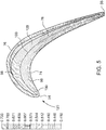
- FIG. 5 demonstrates relative changes in the ratio as are encountered by providing no divider 80
- FIGS. 6-7 demonstrate relative changes in the ratio by changing the location of the divider 80 within the squealer tip pocket 78.
- FIG. 5 shows the squealer tip pocket 78 without a divider 80 therein.
- the highest ratio, and thus the highest pressure areas, are unevenly dispersed in various areas near the leading edge 54 and at both convex and convex sides 74, 76, as demonstrated by areas 98.
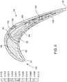
- FIG. 6 shows the addition of the divider 80 within the squealer tip pocket 78.
- the highest ratio area 98 is concentrated within pocket 82, while the pocket 84 is exposed to lower ratio areas 102, 104, and 106, and a small amount of ratio area 100.
- FIG. 7 shows another embodiment of the squealer tip pocket 78 in which the divider 80 is provided closer to the leading edge 54 than in FIG. 6 . Again, it is shown that the highest pressure ratio areas 98 are concentrated within the pocket 82.
- FIG. 7 provides more room for the pocket 84 to accommodate cooling passages 86, 88 (as shown in FIGS. 3 and 4 ), the pocket 84 also contains a greater amount of pressure ratio areas 100 than does the embodiment of FIG. 6 .
- optimum placement of the divider 80 within the squealer tip pocket 78 along camber line 108, which extends from the leading edge 54 to the trailing edge 56, may be selected to balance high pressure concentration within pocket 82 with maximizing the area of pocket 84.
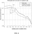
- FIG. 8 demonstrates the pressure ratio Ps(squealer)/Pt(inlet) along the camber line 108, normalized chamber span, of the squealer tip 58 for each of the embodiments shown in FIGS.
- Line 110 in the chart refers to pressure ratio along the camber line 108 for the squealer tip of FIG. 5 having no divider
- line 112 in the chart refers to pressure ratio along the camber line 108 for the squealer tip 58 of FIG. 6 having divider 80
- line 114 in the chart refers to pressure ratio along the camber line 108 for the squealer tip 58 of FIG.
- FIG. 8 thus further demonstrates how the divider 80 creates a high (or at least higher) pressure section in pocket 82 and a low (or at least lower) pressure section in pocket 84.
- PS divider refers to the static pressure at the divider 80 and PT inlet refers to the upstream inlet average total pressure, in other words the total pressure that passes around airfoil 46 at the leading edge 54 in the gas path 16, with inlet 120 illustratively depicted in FIGS. 5-7 .
- the divider location for line 114 represents approximately 0.72 of PS divider / PT inlet and the divider location for line 112 represents approximately 0.66 of PS divider / PT inlet , which are within the range of 0.55 to 0.75.
- the divider 80 is located somewhere between, or including, locations between what is shown in FIGS. 7 and 8 .
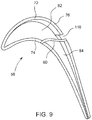
- the rim 72 may include a fluid passage 116, such as a fluid passage 116 in the convex side 76 of the rim 72.
- the fluid passage 116 could be provided at an alternate location.
- the cooling passages 86, 88 are not shown but are further included in the second pocket 84 as shown in FIGS. 3 and 4 .
- a method of managing pressure at a tip 58 of an airfoil 46 is also provided.
- the method may include, for example, flowing the cooling media through the cooling passages 86, 88 and into the pocket 84 defined by the tip plate 70, rim 72, and divider 80.
- the method may further include blocking the cooling media from the pocket 82 separated from pocket 84 by divider 80. Blocking the cooling media from the pocket 82 may either be accomplished by plugging a cooling passage that would otherwise be directed into the pocket 82 or by redirecting the cooling fluid using redirected flow paths into the pocket 84.
- various embodiments of the present invention include an airfoil 46 and a method for managing pressure at the tip 58 of the airfoil 46.
- the airfoil 46 includes a rim 72 that extends radially outward from a tip plate 70 at the outer radial end 60 to at least partially define a squealer tip pocket 78.
- a divider 80 extends across the tip plate 70 to separate the squealer tip pocket 78 into at least two pockets 82, 84, and a plurality of cooling passages 86, 88 provide fluid communication for a cooling media to flow through the tip plate 70 to lower pressure pocket 84.
- a fluid passage 116 in the rim 72 may provide fluid communication for the cooling media to flow across the rim 72 and out of one of the pockets 82, 84.
- the terms “first,” “second,” and “third” may be used interchangeably to distinguish one component from another and are not intended to signify location or importance of the individual components.
- upstream and downstream refer to the relative location of components in a fluid pathway. For example, component A is upstream from component B if a fluid flows from component A to component B. Conversely, component B is downstream from component A if component B receives a fluid flow from component A.
Landscapes
- Engineering & Computer Science (AREA)
- Mechanical Engineering (AREA)
- General Engineering & Computer Science (AREA)
- Turbine Rotor Nozzle Sealing (AREA)
Applications Claiming Priority (1)
| Application Number | Priority Date | Filing Date | Title |
|---|---|---|---|
| US14/639,374 US20160258302A1 (en) | 2015-03-05 | 2015-03-05 | Airfoil and method for managing pressure at tip of airfoil |
Publications (1)
| Publication Number | Publication Date |
|---|---|
| EP3064714A1 true EP3064714A1 (fr) | 2016-09-07 |
Family
ID=55588052
Family Applications (1)
| Application Number | Title | Priority Date | Filing Date |
|---|---|---|---|
| EP16158425.5A Withdrawn EP3064714A1 (fr) | 2015-03-05 | 2016-03-03 | Profil, aube rotorique et procédés associés |
Country Status (4)
| Country | Link |
|---|---|
| US (1) | US20160258302A1 (fr) |
| EP (1) | EP3064714A1 (fr) |
| JP (1) | JP2016160938A (fr) |
| CN (1) | CN105937411A (fr) |
Cited By (2)
| Publication number | Priority date | Publication date | Assignee | Title |
|---|---|---|---|---|
| EP3382152A1 (fr) * | 2017-03-28 | 2018-10-03 | United Technologies Corporation | Conception de refroidissement de pointe d'aube |
| US10822960B2 (en) | 2016-09-14 | 2020-11-03 | Rolls-Royce Plc | Turbine blade cooling |
Families Citing this family (2)
| Publication number | Priority date | Publication date | Assignee | Title |
|---|---|---|---|---|
| US10787932B2 (en) * | 2018-07-13 | 2020-09-29 | Honeywell International Inc. | Turbine blade with dust tolerant cooling system |
| JP7246959B2 (ja) * | 2019-02-14 | 2023-03-28 | 三菱重工コンプレッサ株式会社 | タービン翼及び蒸気タービン |
Citations (7)
| Publication number | Priority date | Publication date | Assignee | Title |
|---|---|---|---|---|
| GB2155558A (en) * | 1984-03-10 | 1985-09-25 | Rolls Royce | Turbomachinery rotor blades |
| US4606701A (en) * | 1981-09-02 | 1986-08-19 | Westinghouse Electric Corp. | Tip structure for a cooled turbine rotor blade |
| DE19963375A1 (de) * | 1999-12-28 | 2001-07-12 | Abb Alstom Power Ch Ag | Schaufel für den Rotor einer Gasturbine sowie Gasturbine mit einer solchen Schaufel |
| US20100166566A1 (en) * | 2008-12-26 | 2010-07-01 | General Electric Company | Turbine rotor blade tips that discourage cross-flow |
| EP2243930A2 (fr) * | 2009-04-17 | 2010-10-27 | General Electric Company | Extrémité d'aube rotorique de turbine |
| US20100303625A1 (en) * | 2009-05-27 | 2010-12-02 | Craig Miller Kuhne | Recovery tip turbine blade |
| EP2716870A1 (fr) * | 2012-10-05 | 2014-04-09 | General Electric Company | Aube rotorique, turbine et procédé de refroidissement d'une aube rotorique associés |
Family Cites Families (10)
| Publication number | Priority date | Publication date | Assignee | Title |
|---|---|---|---|---|
| MX155481A (es) * | 1981-09-02 | 1988-03-17 | Westinghouse Electric Corp | Pala de rotor de turbina |
| US4761116A (en) * | 1987-05-11 | 1988-08-02 | General Electric Company | Turbine blade with tip vent |
| US6554575B2 (en) * | 2001-09-27 | 2003-04-29 | General Electric Company | Ramped tip shelf blade |
| FR2889243B1 (fr) * | 2005-07-26 | 2007-11-02 | Snecma | Aube de turbomachine |
| GB0523469D0 (en) * | 2005-11-18 | 2005-12-28 | Rolls Royce Plc | Blades for gas turbine engines |
| US8500396B2 (en) * | 2006-08-21 | 2013-08-06 | General Electric Company | Cascade tip baffle airfoil |
| US8632311B2 (en) * | 2006-08-21 | 2014-01-21 | General Electric Company | Flared tip turbine blade |
| JP5029957B2 (ja) * | 2007-11-01 | 2012-09-19 | 株式会社Ihi | スキーラ付きタービン動翼 |
| US8801377B1 (en) * | 2011-08-25 | 2014-08-12 | Florida Turbine Technologies, Inc. | Turbine blade with tip cooling and sealing |
| US9951629B2 (en) * | 2012-07-03 | 2018-04-24 | United Technologies Corporation | Tip leakage flow directionality control |
-
2015
- 2015-03-05 US US14/639,374 patent/US20160258302A1/en not_active Abandoned
-
2016
- 2016-02-26 JP JP2016035005A patent/JP2016160938A/ja active Pending
- 2016-03-03 EP EP16158425.5A patent/EP3064714A1/fr not_active Withdrawn
- 2016-03-04 CN CN201610122793.3A patent/CN105937411A/zh active Pending
Patent Citations (7)
| Publication number | Priority date | Publication date | Assignee | Title |
|---|---|---|---|---|
| US4606701A (en) * | 1981-09-02 | 1986-08-19 | Westinghouse Electric Corp. | Tip structure for a cooled turbine rotor blade |
| GB2155558A (en) * | 1984-03-10 | 1985-09-25 | Rolls Royce | Turbomachinery rotor blades |
| DE19963375A1 (de) * | 1999-12-28 | 2001-07-12 | Abb Alstom Power Ch Ag | Schaufel für den Rotor einer Gasturbine sowie Gasturbine mit einer solchen Schaufel |
| US20100166566A1 (en) * | 2008-12-26 | 2010-07-01 | General Electric Company | Turbine rotor blade tips that discourage cross-flow |
| EP2243930A2 (fr) * | 2009-04-17 | 2010-10-27 | General Electric Company | Extrémité d'aube rotorique de turbine |
| US20100303625A1 (en) * | 2009-05-27 | 2010-12-02 | Craig Miller Kuhne | Recovery tip turbine blade |
| EP2716870A1 (fr) * | 2012-10-05 | 2014-04-09 | General Electric Company | Aube rotorique, turbine et procédé de refroidissement d'une aube rotorique associés |
Cited By (3)
| Publication number | Priority date | Publication date | Assignee | Title |
|---|---|---|---|---|
| US10822960B2 (en) | 2016-09-14 | 2020-11-03 | Rolls-Royce Plc | Turbine blade cooling |
| EP3382152A1 (fr) * | 2017-03-28 | 2018-10-03 | United Technologies Corporation | Conception de refroidissement de pointe d'aube |
| US11434770B2 (en) | 2017-03-28 | 2022-09-06 | Raytheon Technologies Corporation | Tip cooling design |
Also Published As
| Publication number | Publication date |
|---|---|
| US20160258302A1 (en) | 2016-09-08 |
| CN105937411A (zh) | 2016-09-14 |
| JP2016160938A (ja) | 2016-09-05 |
Similar Documents
| Publication | Publication Date | Title |
|---|---|---|
| EP2716870B1 (fr) | Aube rotorique et turbine associée | |
| JP6266231B2 (ja) | タービンロータブレード先端における冷却構造 | |
| US8858175B2 (en) | Film hole trench | |
| EP3088675B1 (fr) | Aube rotorique et turbine à gaz associée | |
| CN100582438C (zh) | 受控的泄漏销和振动阻尼器 | |
| JP6824611B2 (ja) | タービンロータブレード | |
| EP2290193B1 (fr) | Aube statorique | |
| JP6514511B2 (ja) | 2つの部分スパンシュラウドおよび湾曲したダブテールを有する高翼弦動翼 | |
| EP3088674B1 (fr) | Pale de rotor et turbine à gaz associée | |
| US9938835B2 (en) | Method and systems for providing cooling for a turbine assembly | |
| US9121298B2 (en) | Finned seal assembly for gas turbine engines | |
| US10066488B2 (en) | Turbomachine blade with generally radial cooling conduit to wheel space | |
| EP3064714A1 (fr) | Profil, aube rotorique et procédés associés | |
| US10247009B2 (en) | Cooling passage for gas turbine system rotor blade | |
| US20140044557A1 (en) | Turbine blade and method for cooling the turbine blade | |
| EP3647544B1 (fr) | Profil d'aube statorique refroidie d'une turbine à gaz | |
| EP3165713A1 (fr) | Aube de turbine | |
| US10738638B2 (en) | Rotor blade with wheel space swirlers and method for forming a rotor blade with wheel space swirlers | |
| US20250163813A1 (en) | Airfoil assembly with platform cooling | |
| KR20250049954A (ko) | 냉각 통로 출구 개구부 단면적의 목표로 한 변경에 의한 터빈 시스템 구성요소 냉각제의 열 프로파일 기반 방향전환 |
Legal Events
| Date | Code | Title | Description |
|---|---|---|---|
| PUAI | Public reference made under article 153(3) epc to a published international application that has entered the european phase |
Free format text: ORIGINAL CODE: 0009012 |
|
| AK | Designated contracting states |
Kind code of ref document: A1 Designated state(s): AL AT BE BG CH CY CZ DE DK EE ES FI FR GB GR HR HU IE IS IT LI LT LU LV MC MK MT NL NO PL PT RO RS SE SI SK SM TR |
|
| AX | Request for extension of the european patent |
Extension state: BA ME |
|
| 17P | Request for examination filed |
Effective date: 20170307 |
|
| RBV | Designated contracting states (corrected) |
Designated state(s): AL AT BE BG CH CY CZ DE DK EE ES FI FR GB GR HR HU IE IS IT LI LT LU LV MC MK MT NL NO PL PT RO RS SE SI SK SM TR |
|
| STAA | Information on the status of an ep patent application or granted ep patent |
Free format text: STATUS: EXAMINATION IS IN PROGRESS |
|
| 17Q | First examination report despatched |
Effective date: 20200903 |
|
| STAA | Information on the status of an ep patent application or granted ep patent |
Free format text: STATUS: THE APPLICATION IS DEEMED TO BE WITHDRAWN |
|
| 18D | Application deemed to be withdrawn |
Effective date: 20201001 |