EP3064775B1 - Pompe à vide et procédé de détection d'un contact entre au moins un rotor et un stator d'une pompe à vide - Google Patents
Pompe à vide et procédé de détection d'un contact entre au moins un rotor et un stator d'une pompe à vide Download PDFInfo
- Publication number
- EP3064775B1 EP3064775B1 EP15157105.6A EP15157105A EP3064775B1 EP 3064775 B1 EP3064775 B1 EP 3064775B1 EP 15157105 A EP15157105 A EP 15157105A EP 3064775 B1 EP3064775 B1 EP 3064775B1
- Authority
- EP
- European Patent Office
- Prior art keywords
- contact
- sensor
- housing
- vacuum pump
- piston
- Prior art date
- Legal status (The legal status is an assumption and is not a legal conclusion. Google has not performed a legal analysis and makes no representation as to the accuracy of the status listed.)
- Not-in-force
Links
Images

Classifications
-
- F—MECHANICAL ENGINEERING; LIGHTING; HEATING; WEAPONS; BLASTING
- F04—POSITIVE - DISPLACEMENT MACHINES FOR LIQUIDS; PUMPS FOR LIQUIDS OR ELASTIC FLUIDS
- F04C—ROTARY-PISTON, OR OSCILLATING-PISTON, POSITIVE-DISPLACEMENT MACHINES FOR LIQUIDS; ROTARY-PISTON, OR OSCILLATING-PISTON, POSITIVE-DISPLACEMENT PUMPS
- F04C25/00—Adaptations of pumps for special use of pumps for elastic fluids
- F04C25/02—Adaptations of pumps for special use of pumps for elastic fluids for producing high vacuum
-
- F—MECHANICAL ENGINEERING; LIGHTING; HEATING; WEAPONS; BLASTING
- F04—POSITIVE - DISPLACEMENT MACHINES FOR LIQUIDS; PUMPS FOR LIQUIDS OR ELASTIC FLUIDS
- F04C—ROTARY-PISTON, OR OSCILLATING-PISTON, POSITIVE-DISPLACEMENT MACHINES FOR LIQUIDS; ROTARY-PISTON, OR OSCILLATING-PISTON, POSITIVE-DISPLACEMENT PUMPS
- F04C28/00—Control of, monitoring of, or safety arrangements for, pumps or pumping installations specially adapted for elastic fluids
- F04C28/28—Safety arrangements; Monitoring
-
- F—MECHANICAL ENGINEERING; LIGHTING; HEATING; WEAPONS; BLASTING
- F04—POSITIVE - DISPLACEMENT MACHINES FOR LIQUIDS; PUMPS FOR LIQUIDS OR ELASTIC FLUIDS
- F04C—ROTARY-PISTON, OR OSCILLATING-PISTON, POSITIVE-DISPLACEMENT MACHINES FOR LIQUIDS; ROTARY-PISTON, OR OSCILLATING-PISTON, POSITIVE-DISPLACEMENT PUMPS
- F04C29/00—Component parts, details or accessories of pumps or pumping installations, not provided for in groups F04C18/00 - F04C28/00
- F04C29/0042—Driving elements, brakes, couplings, transmissions specially adapted for pumps
-
- F—MECHANICAL ENGINEERING; LIGHTING; HEATING; WEAPONS; BLASTING
- F04—POSITIVE - DISPLACEMENT MACHINES FOR LIQUIDS; PUMPS FOR LIQUIDS OR ELASTIC FLUIDS
- F04C—ROTARY-PISTON, OR OSCILLATING-PISTON, POSITIVE-DISPLACEMENT MACHINES FOR LIQUIDS; ROTARY-PISTON, OR OSCILLATING-PISTON, POSITIVE-DISPLACEMENT PUMPS
- F04C18/00—Rotary-piston pumps specially adapted for elastic fluids
- F04C18/08—Rotary-piston pumps specially adapted for elastic fluids of intermeshing-engagement type, i.e. with engagement of co-operating members similar to that of toothed gearing
- F04C18/12—Rotary-piston pumps specially adapted for elastic fluids of intermeshing-engagement type, i.e. with engagement of co-operating members similar to that of toothed gearing of other than internal-axis type
- F04C18/126—Rotary-piston pumps specially adapted for elastic fluids of intermeshing-engagement type, i.e. with engagement of co-operating members similar to that of toothed gearing of other than internal-axis type with radially from the rotor body extending elements, not necessarily co-operating with corresponding recesses in the other rotor, e.g. lobes, Roots type
-
- F—MECHANICAL ENGINEERING; LIGHTING; HEATING; WEAPONS; BLASTING
- F04—POSITIVE - DISPLACEMENT MACHINES FOR LIQUIDS; PUMPS FOR LIQUIDS OR ELASTIC FLUIDS
- F04C—ROTARY-PISTON, OR OSCILLATING-PISTON, POSITIVE-DISPLACEMENT MACHINES FOR LIQUIDS; ROTARY-PISTON, OR OSCILLATING-PISTON, POSITIVE-DISPLACEMENT PUMPS
- F04C18/00—Rotary-piston pumps specially adapted for elastic fluids
- F04C18/08—Rotary-piston pumps specially adapted for elastic fluids of intermeshing-engagement type, i.e. with engagement of co-operating members similar to that of toothed gearing
- F04C18/12—Rotary-piston pumps specially adapted for elastic fluids of intermeshing-engagement type, i.e. with engagement of co-operating members similar to that of toothed gearing of other than internal-axis type
- F04C18/14—Rotary-piston pumps specially adapted for elastic fluids of intermeshing-engagement type, i.e. with engagement of co-operating members similar to that of toothed gearing of other than internal-axis type with toothed rotary pistons
- F04C18/16—Rotary-piston pumps specially adapted for elastic fluids of intermeshing-engagement type, i.e. with engagement of co-operating members similar to that of toothed gearing of other than internal-axis type with toothed rotary pistons with helical teeth, e.g. chevron-shaped, screw type
-
- F—MECHANICAL ENGINEERING; LIGHTING; HEATING; WEAPONS; BLASTING
- F04—POSITIVE - DISPLACEMENT MACHINES FOR LIQUIDS; PUMPS FOR LIQUIDS OR ELASTIC FLUIDS
- F04C—ROTARY-PISTON, OR OSCILLATING-PISTON, POSITIVE-DISPLACEMENT MACHINES FOR LIQUIDS; ROTARY-PISTON, OR OSCILLATING-PISTON, POSITIVE-DISPLACEMENT PUMPS
- F04C2230/00—Manufacture
- F04C2230/60—Assembly methods
- F04C2230/602—Gap; Clearance
-
- F—MECHANICAL ENGINEERING; LIGHTING; HEATING; WEAPONS; BLASTING
- F04—POSITIVE - DISPLACEMENT MACHINES FOR LIQUIDS; PUMPS FOR LIQUIDS OR ELASTIC FLUIDS
- F04C—ROTARY-PISTON, OR OSCILLATING-PISTON, POSITIVE-DISPLACEMENT MACHINES FOR LIQUIDS; ROTARY-PISTON, OR OSCILLATING-PISTON, POSITIVE-DISPLACEMENT PUMPS
- F04C2240/00—Components
- F04C2240/60—Shafts
-
- F—MECHANICAL ENGINEERING; LIGHTING; HEATING; WEAPONS; BLASTING
- F04—POSITIVE - DISPLACEMENT MACHINES FOR LIQUIDS; PUMPS FOR LIQUIDS OR ELASTIC FLUIDS
- F04C—ROTARY-PISTON, OR OSCILLATING-PISTON, POSITIVE-DISPLACEMENT MACHINES FOR LIQUIDS; ROTARY-PISTON, OR OSCILLATING-PISTON, POSITIVE-DISPLACEMENT PUMPS
- F04C2240/00—Components
- F04C2240/80—Other components
- F04C2240/81—Sensor, e.g. electronic sensor for control or monitoring
Definitions
- the invention relates to a vacuum pump and a method for detecting a contact between at least one rotor and a stator of a vacuum pump.
- twin-shaft vacuum pump is, for example, from DE 10 2008 060 540 A1 known.
- Two-shaft vacuum pumps are, for example, Roots vacuum pumps or screw vacuum pumps.
- US2012/025800A1 includes a device for monitoring the wear of pump liners.
- This device has a wear sensor which is arranged in a housing of the pump.
- a loop of an electrical conductor is arranged in the wear detector and the conductor is connected to a controller.
- a controller monitors whether various circuit loops in the wear sensor are functioning.
- This prior art device has the disadvantage of being relatively expensive and requiring separate circuitry.
- a vacuum pump which has one or more temperature sensors which are arranged in the region of the rotor in order to be able to detect heating of the rotor.
- a proximity sensor can also be provided.
- a proximity sensor has the disadvantage that the gaps in the pump between the rotor and the stator must remain relatively large since a proximity sensor works with a relatively large tolerance.
- Roots vacuum pumps and screw vacuum pumps are cooled via the surface of their housing. Heat is therefore released from the pump surface to the environment. In continuous operation and under constant conditions, an equilibrium is established for the input power and the waste heat. In this state, the various components, whose linear expansion depends on the temperature, have a constant gap size between the moving parts and the stationary parts.
- the gaps between the piston or screw and the housing, in particular the end shield, largely determine the operational safety against so-called bumping as well as the level of the vacuum parameters such as pumping speed, compression capacity and ultimate pressure.
- a first problem here is that due to the reduced thermal conductivity in the vacuum, rapid changes in the input variables lead to build-up between the rotor and the housing or the end shield.
- a second problem is that the size of the gap between the pumping rotor and the stationary housing components (stator) is of particular importance for the operational reliability of these pumps. Deposits and contamination in the suction chamber make it difficult to measure the gap size directly.
- the technical problem on which the invention is based is to specify a vacuum pump in which so-called starters can be detected at an early stage, and to specify a method for detecting a contact between at least one rotor and a stator of a vacuum pump, with which contact can also be detected at an early stage, so that the vacuum pump is protected as completely as possible from consequential damage caused by these so-called start-ups.
- the vacuum pump according to the invention with a housing, two shafts arranged in the housing and rotatably driven via a drive and with a gear coupled to the shafts, in which between a piston arranged on the shaft or a screw arranged on the shaft and an inside of the housing or of a stator, at least one sensor and at least one stop element or at least one sensor and at least one abrasion element is arranged, is characterized in that at least one acceleration sensor or at least one vibration sensor is provided, which acts as a signal in the event of contact between the piston or the screw and the Stop element or the abrasion element is formed with an acceleration sensor or vibration sensor that detects a signal that is characteristic of the contact, and that the at least one stop element or the at least one abrasion element has a lower height than the gap height provided during normal operation between K piston or screw and inside of the housing or stator.
- the shaft expands with the piston, or if the housing shrinks, the pistons or the screws hit the stop element, which in turn can be detected by a vibration sensor. If a sensor is arranged in the gap, the sensor will be damaged by the contact, which can be detected by an evaluation unit. If a contact is detected accordingly, the specified measures can be taken, for example additional cooling can be provided or the drive motor is braked or switched off.
- the at least one stop element or at least an abrasion element has a lower height than the gap height provided during normal operation between the piston or screw and the inside of the housing or stator. This means that during normal operation the piston or the screw does not strike the stop element or the sensor or the wear element.
- the vacuum pump is designed in such a way that at least one acceleration sensor or at least one vibration sensor is provided.
- These sensors are used to detect contact between the piston or screw and the inside of the housing or stator.
- the method according to the invention for detecting a contact between at least one rotor and a stator of a vacuum pump is characterized in that at least one acceleration sensor or at least one vibration sensor is provided which, when there is contact between the piston or the screw and the stop element or the wear element signal characteristic of the contact is detected.
- a signal is detected by the at least one acceleration sensor and/or at least one vibration sensor. If this signal exceeds a threshold value at one or more fixed frequencies for the respective speed, this means that there is an imbalance or bearing damage or the like.
- a further embodiment of the inventive method for detecting a contact between at least a rotor and a stator of a vacuum pump is characterized in that when the piston or the screw comes into contact with the at least one sensor, an evaluation unit detects the contact and/or the destruction of the sensor.
- an evaluation unit which evaluates signals from the at least one acceleration sensor or from the at least one vibration sensor.
- This evaluation unit is advantageous for detecting contact according to the various possibilities and for initiating the necessary measures to avoid consequential damage.
- the evaluation unit triggers measures to prevent damage when it detects the beginning of contact between the rotor and stator. These measures can be, for example, braking or switching off the drive motor, rotor cooling or the like.
- acceleration and/or vibration sensors are used to determine whether a signal exceeds a threshold value at one or more fixed frequencies for the respective rotational speed.
- the piston and/or the screws advantageously have one or more additional elements in the area between the largest diameter of the rotor (overspeed range wiper) or also the target contour of the piston or the screw and the inside of the housing or stator. These elements can be placed in the piston or in the screw as well as in the housing or in the stator. The elements create the narrowest gap between the rotor and the housing, which disappears when the temperature balance is disturbed and, on contact, generates a percussive signal at a multiple of the rotational frequency of the rotor.
- Another embodiment provides that a vibration sensor on the side opposite the sensor measures a particularly strong signal that clearly stands out from the background noise of the same frequency.
- the impact frequency can be shifted to a range that is more suitable for detection.
- Complex frequency analyzes can be dispensed with here.
- the invention advantageously relates to double-shaft pumps. This can be Roots pumps or screw pumps.
- the vacuum pump has a housing and that the housing is designed symmetrically in the area where the two shafts are accommodated. This symmetrical design of the housing supports and simplifies the design.
- the transmission has gear wheels and the gear wheels are designed as gear wheels with straight teeth. If the transmission gears are straight-toothed, no axial forces occur due to the toothing. This makes it possible to work with narrow axial gaps.
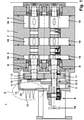
- FIG. 1 shows a section through a vacuum pump 1, the housing 2 of which essentially has two housing parts 3 and 4, namely suction chambers 3 and a gear chamber 4 provided with a lubricant reservoir 5.
- the vacuum pump shown is a Roots vacuum pump.
- Two shafts 6 and 7 are mounted in the housing 2 so as to be horizontally rotatable via roller bearings 8 .
- the shaft 6 is driven by a drive (not shown), for example an asynchronous motor.
- the asynchronous motor acts on a clutch 9.
- a gear 11 is arranged as part of a gear 10 in the gear chamber 4 the shaft 7 mounted second gear 12 is engaged.
- the housing part 4 having the transmission 10 can be closed off from the environment via a transmission cover 13 which can be fixed to the rest of the housing 2 .
- Pistons 14 and 15 are arranged on the parts of the shafts 6 and 7 that pass through the suction chambers 3, which cause the pumping effect when the shafts 6 and 7 rotate and suck fluid into the suction chambers 3 via at least one suction opening (not shown) and via at least one Discharge opening (not shown) discharge from the suction chambers 3 again.
- the pistons 14, 15 are designed as double-arched rotors.
- the cross-sectional shape of the pistons 14, 15 is approximately in the shape of the figure "8".
- the pistons 14, 15 are arranged in a rotor chamber formed by the housing part 3 with a minimum distance between a peripheral surface of the housing part 3 and the pistons 14, 15. Furthermore, when the pistons 14, 15 are engaged with each other, they have formed a minimum distance between them to prevent them from directly engaging or interfering with each other.
- the drive shaft 6 is rotated by the drive, for example an electric motor. Thereby, the output shaft 7 is rotated in the opposite direction to the drive shaft 6 by the meshing relationship between a drive gear 11 and a driven gear 12, and the drive rotor with pistons 15 and the driven rotor with pistons 14 are rotated accordingly.
- both the gears 11 and 12 and the rolling bearings 8 must be supplied with a lubricant in order to cool them and to avoid increased wear.
- the gear chamber 4 has a lubricant reservoir 5 filled with a lubricant.
- a centrifugal disc 16 arranged on the shaft 6 dips into the lubricant reservoir 5 and distributes the lubricant throughout the entire gear chamber 4 and in particular feeds it to the roller bearings 8 and the gear wheels 11 and 12 .
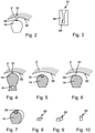
- FIG. 2 shows an abrasion element 31 which is arranged in a housing 2 on a housing inner side 32 .
- the piston 14 also has a further wear element 33 .
- the wear elements 31, 33 come into contact and generate an impact signal which is detected by a vibration sensor (not shown).
- the abrasion element 31 in which, for example, a wire 34 can be arranged.
- the abrasion element 31 consists of a base body 35, which consists for example of plastic or ceramic.
- the wire 34 is embedded in the base body 35 . If the base body 35 is sheared off upon contact between the abrasion element 33 and the abrasion element 31, an electrical contact that was established by the wire 34 is interrupted. This interruption is detected by an evaluation unit (not shown) and suitable measures can be taken, for example a drive motor is slowed down or switched off.
- FIG. 4 shows the piston 14, which is arranged on the shaft 6.
- An abrasion element 31 is arranged in the housing 2 on the housing inner wall 32 .
- a signal is detected with an acceleration and/or vibration sensor. If the signal exceeds a threshold at one or more fixed frequencies for that speed, this is an indication that contact is occurring. In this case, the drive motor can be switched off. This avoids a so-called collision between the piston 14 and the inner wall 32 of the housing, which would damage the vacuum pump.
- FIG. 5 shows a modified embodiment in which the piston 14 carries a wear element 31.
- FIG. In this case, the housing 2 with the housing inside 32 has no additional element.
- abrasion element 31 As in 6 shown to form the abrasion element 31 as a sensor, such as in figure 5 shown.
- an abrasion element 33 can be arranged on the pistons 14 .
- the wear element can be cuboid, as in FIG 8 shown.
- the abrasion element 33 can have rounded edges, as in FIG 9 shown.
- the abrasion element 33 can also be cylindrical, as in 10 shown.
- the housing 2 has an inlet 39 and an outlet 40 .
- the 12 and 13 show the wear element 33, which is arranged, for example, on the piston 14.
- the abrasion element 33 has a small contact surface 41 . Due to the fact that the possible contact surface 41 with the housing 2 is very small, this leads to minimal friction and low waste heat for contact detection in the event of contact. The main focus here is detection and not improved damage tolerance.
Landscapes
- Engineering & Computer Science (AREA)
- Mechanical Engineering (AREA)
- General Engineering & Computer Science (AREA)
- Applications Or Details Of Rotary Compressors (AREA)
- Compressors, Vaccum Pumps And Other Relevant Systems (AREA)
Claims (5)
- Pompe à vide munie d'un boîtier, de deux arbres agencés dans le boîtier, entraînés en rotation par l'intermédiaire d'un entraînement, ainsi que d'une transmission couplée aux arbres, dans laquelle sont agencés, entre un piston (14, 15) agencé sur l'arbre (6, 7) ou une vis agencée sur l'arbre et un côté intérieur (32) du boîtier (2) ou d'un stator,- au moins un capteur (38) et au moins un élément de butée (31, 33) ou- au moins un capteur (38) et un élément d'abrasion (31, 33),caractérisée en ce qu'au moins un capteur d'accélération ou au moins un capteur d'oscillation est prévu, qui est configuré sous la forme d'un capteur d'accélération ou d'un capteur d'oscillation détectant, lors d'un contact entre le piston ou la vis et l'élément de butée (31, 33) ou l'élément d'abrasion (31, 33), un signal caractéristique du contact, et en ce que l'au moins un élément de butée (31, 33) ou l'au moins un élément d'abrasion (31, 33) présente une hauteur plus faible que la hauteur d'interstice prévue en fonctionnement normal entre le piston (14) ou la vis et le côté intérieur (32) du boîtier (2) ou du stator.
- Procédé pour la détection d'un contact entre au moins un rotor et un stator d'une pompe à vide présentant les caractéristiques selon la revendication 1, caractérisé en ce qu'au moins un capteur d'accélération ou au moins un capteur d'oscillation est prévu, qui détecte, lors d'un contact entre le piston (14, 15) ou la vis et l'élément de butée (31, 33) ou l'au moins un élément d'abrasion (31, 33), un signal caractéristique du contact.
- Procédé selon la revendication 2 pour la détection d'un contact entre l'au moins un rotor et un stator d'une pompe à vide, caractérisé en ce que lors d'un contact du piston (14, 15) ou de la vis avec l'au moins un capteur (38), une unité d'évaluation détecte le contact.
- Procédé selon la revendication 3, caractérisé en ce qu'une unité d'évaluation est prévue, qui évalue des signaux de l'au moins un capteur.
- Procédé selon la revendication 4, caractérisé en ce que l'unité d'évaluation déclenche des mesures pour éviter des dégâts lorsqu'un début de contact entre le rotor et le stator est constaté.
Priority Applications (1)
| Application Number | Priority Date | Filing Date | Title |
|---|---|---|---|
| EP15157105.6A EP3064775B1 (fr) | 2015-03-02 | 2015-03-02 | Pompe à vide et procédé de détection d'un contact entre au moins un rotor et un stator d'une pompe à vide |
Applications Claiming Priority (1)
| Application Number | Priority Date | Filing Date | Title |
|---|---|---|---|
| EP15157105.6A EP3064775B1 (fr) | 2015-03-02 | 2015-03-02 | Pompe à vide et procédé de détection d'un contact entre au moins un rotor et un stator d'une pompe à vide |
Publications (2)
| Publication Number | Publication Date |
|---|---|
| EP3064775A1 EP3064775A1 (fr) | 2016-09-07 |
| EP3064775B1 true EP3064775B1 (fr) | 2022-01-26 |
Family
ID=52595175
Family Applications (1)
| Application Number | Title | Priority Date | Filing Date |
|---|---|---|---|
| EP15157105.6A Not-in-force EP3064775B1 (fr) | 2015-03-02 | 2015-03-02 | Pompe à vide et procédé de détection d'un contact entre au moins un rotor et un stator d'une pompe à vide |
Country Status (1)
| Country | Link |
|---|---|
| EP (1) | EP3064775B1 (fr) |
Families Citing this family (2)
| Publication number | Priority date | Publication date | Assignee | Title |
|---|---|---|---|---|
| GB201621618D0 (en) * | 2016-12-19 | 2017-02-01 | Edwards Ltd | Pump sealing |
| GB2588890A (en) * | 2019-10-24 | 2021-05-19 | Edwards Ltd | Sensor assembly |
Family Cites Families (8)
| Publication number | Priority date | Publication date | Assignee | Title |
|---|---|---|---|---|
| JPS5225949A (en) * | 1975-08-23 | 1977-02-26 | Shimadzu Corp | Brake-loaded oil pressure motor |
| US4787831A (en) * | 1983-09-20 | 1988-11-29 | Air Products And Chemicals, Inc. | Dual seal system for roots blower |
| JPS61104187A (ja) * | 1984-10-29 | 1986-05-22 | Hitachi Ltd | 真空ポンプ用軸封装置 |
| FR2812041A1 (fr) * | 2000-07-20 | 2002-01-25 | Cit Alcatel | Principe de refroidissement de pompe a vide |
| WO2010046976A1 (fr) * | 2008-10-22 | 2010-04-29 | 株式会社前川製作所 | Compresseur à vis de ravitaillement |
| DE102008060540A1 (de) | 2008-12-04 | 2010-06-10 | Pfeiffer Vacuum Gmbh | Wälzkolbenvakuumpumpe |
| US8564449B2 (en) * | 2010-01-12 | 2013-10-22 | Siemens Energy, Inc. | Open circuit wear sensor for use with a conductive wear counterface |
| WO2012138522A2 (fr) * | 2011-04-07 | 2012-10-11 | Imo Industries Inc | Système et procédé pour la surveillance d'usure de chemisage de pompe |
-
2015
- 2015-03-02 EP EP15157105.6A patent/EP3064775B1/fr not_active Not-in-force
Also Published As
| Publication number | Publication date |
|---|---|
| EP3064775A1 (fr) | 2016-09-07 |
Similar Documents
| Publication | Publication Date | Title |
|---|---|---|
| EP3545196B1 (fr) | Pompe de refroidissement électrique pour véhicule à moteur | |
| EP2545280B1 (fr) | Systeme de lubrification pour un compresseur à vis | |
| WO2016074660A1 (fr) | Dispositif échangeur de chaleur rotatif | |
| EP3187736B1 (fr) | Pompe centrifuge horizontale multi-etagée destinée au transport d'un fluide et son procédé de réparation | |
| EP2397656A1 (fr) | Procédé de réglage de l'espace radial entre les extrémités de pales d'aubes mobiles et une paroi de canal ainsi que dispositif de mesure d'un espace radial d'une turbomachine pouvant à écoulement axial | |
| EP2645544A1 (fr) | Machine électrique dotée d'un refroidissement interne efficace | |
| EP3640507A1 (fr) | Dispositif de bague d'étanchéité glissante pourvu de microsystème, dispositif de pompage correspondant et son procédé de fonctionnement | |
| DE202015003927U1 (de) | Steuerungselektronik für eine Vakuumpumpe sowie Vakuumpumpe | |
| EP3765748B1 (fr) | Groupe pompe centrifuge et procédé pour déplacer une valve dans un tel groupe pompe centrifuge | |
| EP2566015A1 (fr) | Moteur électrique | |
| EP3064775B1 (fr) | Pompe à vide et procédé de détection d'un contact entre au moins un rotor et un stator d'une pompe à vide | |
| DE102014114837A1 (de) | Kältemittelverdichter | |
| WO2009138201A2 (fr) | Armoire de commande pour éolienne | |
| DE69819293T2 (de) | Hydraulikdichtung | |
| EP3467314B1 (fr) | Pompe à vis | |
| DE102012102405A1 (de) | Kältemittelverdichter | |
| EP2431568B1 (fr) | Pompe à vide avec structure de centrifugation du lubrifiant | |
| DE102015122443B4 (de) | Kältemittelverdichteranlage | |
| EP3080455B1 (fr) | Compresseur | |
| DE102019122642A1 (de) | Vorrichtung und Verfahren zur Überwachung wenigstens eines Gleitlagers | |
| DE102016011394A1 (de) | Schraubenkompressor für ein Nutzfahrzeug | |
| EP2902629A1 (fr) | Pompe à vide avec réfrigérateur de lubrifiant | |
| DE102008046293A1 (de) | Pumpe | |
| DE102019218035B4 (de) | Scrollverdichter | |
| DE112022005628T5 (de) | Elektrischer Verdichter |
Legal Events
| Date | Code | Title | Description |
|---|---|---|---|
| PUAI | Public reference made under article 153(3) epc to a published international application that has entered the european phase |
Free format text: ORIGINAL CODE: 0009012 |
|
| AK | Designated contracting states |
Kind code of ref document: A1 Designated state(s): AL AT BE BG CH CY CZ DE DK EE ES FI FR GB GR HR HU IE IS IT LI LT LU LV MC MK MT NL NO PL PT RO RS SE SI SK SM TR |
|
| AX | Request for extension of the european patent |
Extension state: BA ME |
|
| STAA | Information on the status of an ep patent application or granted ep patent |
Free format text: STATUS: REQUEST FOR EXAMINATION WAS MADE |
|
| 17P | Request for examination filed |
Effective date: 20170301 |
|
| RBV | Designated contracting states (corrected) |
Designated state(s): AL AT BE BG CH CY CZ DE DK EE ES FI FR GB GR HR HU IE IS IT LI LT LU LV MC MK MT NL NO PL PT RO RS SE SI SK SM TR |
|
| STAA | Information on the status of an ep patent application or granted ep patent |
Free format text: STATUS: EXAMINATION IS IN PROGRESS |
|
| 17Q | First examination report despatched |
Effective date: 20200203 |
|
| GRAP | Despatch of communication of intention to grant a patent |
Free format text: ORIGINAL CODE: EPIDOSNIGR1 |
|
| STAA | Information on the status of an ep patent application or granted ep patent |
Free format text: STATUS: GRANT OF PATENT IS INTENDED |
|
| INTG | Intention to grant announced |
Effective date: 20210929 |
|
| GRAS | Grant fee paid |
Free format text: ORIGINAL CODE: EPIDOSNIGR3 |
|
| GRAA | (expected) grant |
Free format text: ORIGINAL CODE: 0009210 |
|
| STAA | Information on the status of an ep patent application or granted ep patent |
Free format text: STATUS: THE PATENT HAS BEEN GRANTED |
|
| AK | Designated contracting states |
Kind code of ref document: B1 Designated state(s): AL AT BE BG CH CY CZ DE DK EE ES FI FR GB GR HR HU IE IS IT LI LT LU LV MC MK MT NL NO PL PT RO RS SE SI SK SM TR |
|
| REG | Reference to a national code |
Ref country code: GB Ref legal event code: FG4D Free format text: NOT ENGLISH |
|
| REG | Reference to a national code |
Ref country code: CH Ref legal event code: EP |
|
| REG | Reference to a national code |
Ref country code: AT Ref legal event code: REF Ref document number: 1465484 Country of ref document: AT Kind code of ref document: T Effective date: 20220215 |
|
| REG | Reference to a national code |
Ref country code: IE Ref legal event code: FG4D Free format text: LANGUAGE OF EP DOCUMENT: GERMAN |
|
| REG | Reference to a national code |
Ref country code: DE Ref legal event code: R096 Ref document number: 502015015594 Country of ref document: DE |
|
| REG | Reference to a national code |
Ref country code: LT Ref legal event code: MG9D |
|
| REG | Reference to a national code |
Ref country code: NL Ref legal event code: MP Effective date: 20220126 |
|
| PG25 | Lapsed in a contracting state [announced via postgrant information from national office to epo] |
Ref country code: NL Free format text: LAPSE BECAUSE OF FAILURE TO SUBMIT A TRANSLATION OF THE DESCRIPTION OR TO PAY THE FEE WITHIN THE PRESCRIBED TIME-LIMIT Effective date: 20220126 |
|
| PG25 | Lapsed in a contracting state [announced via postgrant information from national office to epo] |
Ref country code: SE Free format text: LAPSE BECAUSE OF FAILURE TO SUBMIT A TRANSLATION OF THE DESCRIPTION OR TO PAY THE FEE WITHIN THE PRESCRIBED TIME-LIMIT Effective date: 20220126 Ref country code: RS Free format text: LAPSE BECAUSE OF FAILURE TO SUBMIT A TRANSLATION OF THE DESCRIPTION OR TO PAY THE FEE WITHIN THE PRESCRIBED TIME-LIMIT Effective date: 20220126 Ref country code: PT Free format text: LAPSE BECAUSE OF FAILURE TO SUBMIT A TRANSLATION OF THE DESCRIPTION OR TO PAY THE FEE WITHIN THE PRESCRIBED TIME-LIMIT Effective date: 20220526 Ref country code: NO Free format text: LAPSE BECAUSE OF FAILURE TO SUBMIT A TRANSLATION OF THE DESCRIPTION OR TO PAY THE FEE WITHIN THE PRESCRIBED TIME-LIMIT Effective date: 20220426 Ref country code: LT Free format text: LAPSE BECAUSE OF FAILURE TO SUBMIT A TRANSLATION OF THE DESCRIPTION OR TO PAY THE FEE WITHIN THE PRESCRIBED TIME-LIMIT Effective date: 20220126 Ref country code: HR Free format text: LAPSE BECAUSE OF FAILURE TO SUBMIT A TRANSLATION OF THE DESCRIPTION OR TO PAY THE FEE WITHIN THE PRESCRIBED TIME-LIMIT Effective date: 20220126 Ref country code: ES Free format text: LAPSE BECAUSE OF FAILURE TO SUBMIT A TRANSLATION OF THE DESCRIPTION OR TO PAY THE FEE WITHIN THE PRESCRIBED TIME-LIMIT Effective date: 20220126 Ref country code: BG Free format text: LAPSE BECAUSE OF FAILURE TO SUBMIT A TRANSLATION OF THE DESCRIPTION OR TO PAY THE FEE WITHIN THE PRESCRIBED TIME-LIMIT Effective date: 20220426 |
|
| PG25 | Lapsed in a contracting state [announced via postgrant information from national office to epo] |
Ref country code: PL Free format text: LAPSE BECAUSE OF FAILURE TO SUBMIT A TRANSLATION OF THE DESCRIPTION OR TO PAY THE FEE WITHIN THE PRESCRIBED TIME-LIMIT Effective date: 20220126 Ref country code: LV Free format text: LAPSE BECAUSE OF FAILURE TO SUBMIT A TRANSLATION OF THE DESCRIPTION OR TO PAY THE FEE WITHIN THE PRESCRIBED TIME-LIMIT Effective date: 20220126 Ref country code: GR Free format text: LAPSE BECAUSE OF FAILURE TO SUBMIT A TRANSLATION OF THE DESCRIPTION OR TO PAY THE FEE WITHIN THE PRESCRIBED TIME-LIMIT Effective date: 20220427 Ref country code: FI Free format text: LAPSE BECAUSE OF FAILURE TO SUBMIT A TRANSLATION OF THE DESCRIPTION OR TO PAY THE FEE WITHIN THE PRESCRIBED TIME-LIMIT Effective date: 20220126 |
|
| PG25 | Lapsed in a contracting state [announced via postgrant information from national office to epo] |
Ref country code: IS Free format text: LAPSE BECAUSE OF FAILURE TO SUBMIT A TRANSLATION OF THE DESCRIPTION OR TO PAY THE FEE WITHIN THE PRESCRIBED TIME-LIMIT Effective date: 20220526 |
|
| REG | Reference to a national code |
Ref country code: DE Ref legal event code: R097 Ref document number: 502015015594 Country of ref document: DE |
|
| PG25 | Lapsed in a contracting state [announced via postgrant information from national office to epo] |
Ref country code: SM Free format text: LAPSE BECAUSE OF FAILURE TO SUBMIT A TRANSLATION OF THE DESCRIPTION OR TO PAY THE FEE WITHIN THE PRESCRIBED TIME-LIMIT Effective date: 20220126 Ref country code: SK Free format text: LAPSE BECAUSE OF FAILURE TO SUBMIT A TRANSLATION OF THE DESCRIPTION OR TO PAY THE FEE WITHIN THE PRESCRIBED TIME-LIMIT Effective date: 20220126 Ref country code: RO Free format text: LAPSE BECAUSE OF FAILURE TO SUBMIT A TRANSLATION OF THE DESCRIPTION OR TO PAY THE FEE WITHIN THE PRESCRIBED TIME-LIMIT Effective date: 20220126 Ref country code: MC Free format text: LAPSE BECAUSE OF FAILURE TO SUBMIT A TRANSLATION OF THE DESCRIPTION OR TO PAY THE FEE WITHIN THE PRESCRIBED TIME-LIMIT Effective date: 20220126 Ref country code: EE Free format text: LAPSE BECAUSE OF FAILURE TO SUBMIT A TRANSLATION OF THE DESCRIPTION OR TO PAY THE FEE WITHIN THE PRESCRIBED TIME-LIMIT Effective date: 20220126 Ref country code: DK Free format text: LAPSE BECAUSE OF FAILURE TO SUBMIT A TRANSLATION OF THE DESCRIPTION OR TO PAY THE FEE WITHIN THE PRESCRIBED TIME-LIMIT Effective date: 20220126 |
|
| REG | Reference to a national code |
Ref country code: CH Ref legal event code: PL |
|
| PG25 | Lapsed in a contracting state [announced via postgrant information from national office to epo] |
Ref country code: AL Free format text: LAPSE BECAUSE OF FAILURE TO SUBMIT A TRANSLATION OF THE DESCRIPTION OR TO PAY THE FEE WITHIN THE PRESCRIBED TIME-LIMIT Effective date: 20220126 |
|
| PLBE | No opposition filed within time limit |
Free format text: ORIGINAL CODE: 0009261 |
|
| STAA | Information on the status of an ep patent application or granted ep patent |
Free format text: STATUS: NO OPPOSITION FILED WITHIN TIME LIMIT |
|
| REG | Reference to a national code |
Ref country code: BE Ref legal event code: MM Effective date: 20220331 |
|
| 26N | No opposition filed |
Effective date: 20221027 |
|
| PG25 | Lapsed in a contracting state [announced via postgrant information from national office to epo] |
Ref country code: LU Free format text: LAPSE BECAUSE OF NON-PAYMENT OF DUE FEES Effective date: 20220302 Ref country code: LI Free format text: LAPSE BECAUSE OF NON-PAYMENT OF DUE FEES Effective date: 20220331 Ref country code: IE Free format text: LAPSE BECAUSE OF NON-PAYMENT OF DUE FEES Effective date: 20220302 Ref country code: FR Free format text: LAPSE BECAUSE OF NON-PAYMENT OF DUE FEES Effective date: 20220326 Ref country code: CH Free format text: LAPSE BECAUSE OF NON-PAYMENT OF DUE FEES Effective date: 20220331 |
|
| PG25 | Lapsed in a contracting state [announced via postgrant information from national office to epo] |
Ref country code: SI Free format text: LAPSE BECAUSE OF FAILURE TO SUBMIT A TRANSLATION OF THE DESCRIPTION OR TO PAY THE FEE WITHIN THE PRESCRIBED TIME-LIMIT Effective date: 20220126 Ref country code: BE Free format text: LAPSE BECAUSE OF NON-PAYMENT OF DUE FEES Effective date: 20220331 |
|
| REG | Reference to a national code |
Ref country code: AT Ref legal event code: MM01 Ref document number: 1465484 Country of ref document: AT Kind code of ref document: T Effective date: 20220302 |
|
| PG25 | Lapsed in a contracting state [announced via postgrant information from national office to epo] |
Ref country code: AT Free format text: LAPSE BECAUSE OF NON-PAYMENT OF DUE FEES Effective date: 20220302 |
|
| PG25 | Lapsed in a contracting state [announced via postgrant information from national office to epo] |
Ref country code: HU Free format text: LAPSE BECAUSE OF FAILURE TO SUBMIT A TRANSLATION OF THE DESCRIPTION OR TO PAY THE FEE WITHIN THE PRESCRIBED TIME-LIMIT; INVALID AB INITIO Effective date: 20150302 |
|
| PG25 | Lapsed in a contracting state [announced via postgrant information from national office to epo] |
Ref country code: MK Free format text: LAPSE BECAUSE OF FAILURE TO SUBMIT A TRANSLATION OF THE DESCRIPTION OR TO PAY THE FEE WITHIN THE PRESCRIBED TIME-LIMIT Effective date: 20220126 Ref country code: CY Free format text: LAPSE BECAUSE OF FAILURE TO SUBMIT A TRANSLATION OF THE DESCRIPTION OR TO PAY THE FEE WITHIN THE PRESCRIBED TIME-LIMIT Effective date: 20220126 |
|
| PGFP | Annual fee paid to national office [announced via postgrant information from national office to epo] |
Ref country code: DE Payment date: 20240109 Year of fee payment: 10 Ref country code: CZ Payment date: 20240209 Year of fee payment: 10 Ref country code: GB Payment date: 20240207 Year of fee payment: 10 |
|
| PGFP | Annual fee paid to national office [announced via postgrant information from national office to epo] |
Ref country code: IT Payment date: 20240125 Year of fee payment: 10 |
|
| PG25 | Lapsed in a contracting state [announced via postgrant information from national office to epo] |
Ref country code: MT Free format text: LAPSE BECAUSE OF FAILURE TO SUBMIT A TRANSLATION OF THE DESCRIPTION OR TO PAY THE FEE WITHIN THE PRESCRIBED TIME-LIMIT Effective date: 20220126 |
|
| REG | Reference to a national code |
Ref country code: DE Ref legal event code: R119 Ref document number: 502015015594 Country of ref document: DE |
|
| PG25 | Lapsed in a contracting state [announced via postgrant information from national office to epo] |
Ref country code: CZ Free format text: LAPSE BECAUSE OF NON-PAYMENT OF DUE FEES Effective date: 20250302 |
|
| GBPC | Gb: european patent ceased through non-payment of renewal fee |
Effective date: 20250302 |
|
| PG25 | Lapsed in a contracting state [announced via postgrant information from national office to epo] |
Ref country code: TR Free format text: LAPSE BECAUSE OF FAILURE TO SUBMIT A TRANSLATION OF THE DESCRIPTION OR TO PAY THE FEE WITHIN THE PRESCRIBED TIME-LIMIT Effective date: 20220126 |
|
| PG25 | Lapsed in a contracting state [announced via postgrant information from national office to epo] |
Ref country code: DE Free format text: LAPSE BECAUSE OF NON-PAYMENT OF DUE FEES Effective date: 20251001 |
|
| PG25 | Lapsed in a contracting state [announced via postgrant information from national office to epo] |
Ref country code: GB Free format text: LAPSE BECAUSE OF NON-PAYMENT OF DUE FEES Effective date: 20250302 |
|
| PG25 | Lapsed in a contracting state [announced via postgrant information from national office to epo] |
Ref country code: IT Free format text: LAPSE BECAUSE OF NON-PAYMENT OF DUE FEES Effective date: 20250302 |