EP3064777A1 - Ventilateur à flux transversal et climatiseur - Google Patents
Ventilateur à flux transversal et climatiseur Download PDFInfo
- Publication number
- EP3064777A1 EP3064777A1 EP14859194.4A EP14859194A EP3064777A1 EP 3064777 A1 EP3064777 A1 EP 3064777A1 EP 14859194 A EP14859194 A EP 14859194A EP 3064777 A1 EP3064777 A1 EP 3064777A1
- Authority
- EP
- European Patent Office
- Prior art keywords
- blade
- cross
- impeller
- flow fan
- outlet
- Prior art date
- Legal status (The legal status is an assumption and is not a legal conclusion. Google has not performed a legal analysis and makes no representation as to the accuracy of the status listed.)
- Withdrawn
Links
Images





Classifications
-
- F—MECHANICAL ENGINEERING; LIGHTING; HEATING; WEAPONS; BLASTING
- F04—POSITIVE - DISPLACEMENT MACHINES FOR LIQUIDS; PUMPS FOR LIQUIDS OR ELASTIC FLUIDS
- F04D—NON-POSITIVE-DISPLACEMENT PUMPS
- F04D17/00—Radial-flow pumps, e.g. centrifugal pumps; Helico-centrifugal pumps
- F04D17/02—Radial-flow pumps, e.g. centrifugal pumps; Helico-centrifugal pumps having non-centrifugal stages, e.g. centripetal
- F04D17/04—Radial-flow pumps, e.g. centrifugal pumps; Helico-centrifugal pumps having non-centrifugal stages, e.g. centripetal of transverse-flow type
-
- F—MECHANICAL ENGINEERING; LIGHTING; HEATING; WEAPONS; BLASTING
- F04—POSITIVE - DISPLACEMENT MACHINES FOR LIQUIDS; PUMPS FOR LIQUIDS OR ELASTIC FLUIDS
- F04D—NON-POSITIVE-DISPLACEMENT PUMPS
- F04D29/00—Details, component parts, or accessories
- F04D29/26—Rotors specially for elastic fluids
- F04D29/28—Rotors specially for elastic fluids for centrifugal or helico-centrifugal pumps for radial-flow or helico-centrifugal pumps
- F04D29/281—Rotors specially for elastic fluids for centrifugal or helico-centrifugal pumps for radial-flow or helico-centrifugal pumps for fans or blowers
- F04D29/282—Rotors specially for elastic fluids for centrifugal or helico-centrifugal pumps for radial-flow or helico-centrifugal pumps for fans or blowers the leading edge of each vane being substantially parallel to the rotation axis
- F04D29/283—Rotors specially for elastic fluids for centrifugal or helico-centrifugal pumps for radial-flow or helico-centrifugal pumps for fans or blowers the leading edge of each vane being substantially parallel to the rotation axis rotors of the squirrel-cage type
-
- F—MECHANICAL ENGINEERING; LIGHTING; HEATING; WEAPONS; BLASTING
- F04—POSITIVE - DISPLACEMENT MACHINES FOR LIQUIDS; PUMPS FOR LIQUIDS OR ELASTIC FLUIDS
- F04D—NON-POSITIVE-DISPLACEMENT PUMPS
- F04D29/00—Details, component parts, or accessories
- F04D29/26—Rotors specially for elastic fluids
- F04D29/28—Rotors specially for elastic fluids for centrifugal or helico-centrifugal pumps for radial-flow or helico-centrifugal pumps
- F04D29/30—Vanes
-
- F—MECHANICAL ENGINEERING; LIGHTING; HEATING; WEAPONS; BLASTING
- F04—POSITIVE - DISPLACEMENT MACHINES FOR LIQUIDS; PUMPS FOR LIQUIDS OR ELASTIC FLUIDS
- F04D—NON-POSITIVE-DISPLACEMENT PUMPS
- F04D29/00—Details, component parts, or accessories
- F04D29/66—Combating cavitation, whirls, noise, vibration or the like; Balancing
- F04D29/661—Combating cavitation, whirls, noise, vibration or the like; Balancing especially adapted for elastic fluid pumps
- F04D29/663—Sound attenuation
- F04D29/665—Sound attenuation by means of resonance chambers or interference
-
- F—MECHANICAL ENGINEERING; LIGHTING; HEATING; WEAPONS; BLASTING
- F04—POSITIVE - DISPLACEMENT MACHINES FOR LIQUIDS; PUMPS FOR LIQUIDS OR ELASTIC FLUIDS
- F04D—NON-POSITIVE-DISPLACEMENT PUMPS
- F04D29/00—Details, component parts, or accessories
- F04D29/66—Combating cavitation, whirls, noise, vibration or the like; Balancing
- F04D29/661—Combating cavitation, whirls, noise, vibration or the like; Balancing especially adapted for elastic fluid pumps
- F04D29/667—Combating cavitation, whirls, noise, vibration or the like; Balancing especially adapted for elastic fluid pumps by influencing the flow pattern, e.g. suppression of turbulence
Definitions
- the present invention relates to a cross-flow fan and an air conditioner using the cross-flow fan.
- Patent Literature 1 there is disclosed a transverse fan including blades, each being inclined at a predetermined angle with respect to a fan axis and being mounted with unequally set mounting pitches. Further, in the transverse fan, each blade is thin in an impeller longitudinal direction.
- Patent Literature 2 there is disclosed an axial fan including blades each formed so that a blade cross section orthogonal to a rotational axis decreases in size as approaching from a base portion to a distal end portion of each of the blade portions arranged side by side on a main surface. Further, in the axial fan, a center of the blade cross section orthogonal to the rotational axis is displaced frontward or backward in a direction of rotation about the rotational axis as approaching from the base portion of the blade portion toward the tip portion of the blade portion. Further, the blade cross section is curved radially outward.
- Patent Literature 3 there is disclosed a fan including first components in each of which a tip portion of a blade is inclined in a rotational direction from a base of the blade, and second components in each of which the tip portion of the blade is inclined in a counter-rotational direction from the base of the blade.
- the first components and the second components are alternately stacked.
- the present invention has been made in view of the above, and an object of the present invention is to provide a cross-flow fan capable of suitably dispersing a flow over a rotational axis direction in the entire fan.
- a cross-flow fan including: an impeller; and a shaft configured to support the impeller in a rotatable manner, the impeller including: a plurality of support plates; and a plurality of blades arranged between a corresponding pair of the support plates at intervals in a circumferential direction, each of the plurality of blades having an outer diameter and an inner diameter that are identical in a rotational axis direction between the corresponding pair of the support plates, and including at least one region that is advanced or retreated in a rotational direction.
- each of the plurality of blades may have at least two different blade outlet angles between the corresponding pair of the support plates.
- the each of the plurality of blades may have an outer diameter and an inner diameter that are identical in the rotational axis direction, have a cross-sectional shape and a blade outlet angle that are identical over the rotational axis direction, and include a plurality of the regions that are advanced or retreated in the rotational direction over the rotational axis direction.
- the each of the plurality of blades may be formed bilaterally symmetrically across a central cross-sectional portion, and includes, in an order of increasing a distance from the central cross-sectional portion, a pair of inter-blade-ring center portions 8cb, a pair of inter-blade portions 8cc, and a pair of blade ring vicinity portions 8ca, and as for a blade outlet angle ⁇ b2 and a blade inclination deviation angle ⁇ 2 at the inter-blade-ring center portions, a blade outlet angle ⁇ b3 and a blade inclination deviation angle ⁇ 3 at the inter-blade portions, and a blade outlet angle ⁇ b1 and a blade inclination deviation angle ⁇ 1 at the blade ring vicinity portions, the each of the plurality of blades may be formed so that the blade outlet angles satisfy ⁇ b2 ⁇ b1 ⁇ b3 and the blade inclination deviation angles satisfy ⁇ 3 ⁇ 1 ⁇ 2.
- an air conditioner including: a stabilizer configured to partition an inlet-side air duct and an outlet-side air duct inside a main body; a cross-flow fan arranged between the inlet-side air duct and the outlet-side air duct; a ventilation resistor arranged inside the main body; and a guide wall configured to guide air discharged from the cross-flow fan to an air outlet of the main body, the cross-flow fan being the above-mentioned cross-flow fan according to the one embodiment of the present invention.
- FIG. 1 is an installation schematic view of an air conditioner having a cross-flow fan mounted thereon according to a first embodiment of the present invention when viewed from a room.
- FIG. 2 is a vertical sectional view of the air conditioner of FIG. 1 .
- FIG. 3 is a view for illustrating a front side and a lateral side of an impeller of the cross-flow fan to be mounted on the air conditioner of FIG. 1 .
- an air conditioner (indoor unit) 100 includes a main body 1 and a front panel 1b installed on the front side of the main body 1, which form an outer shape of the air conditioner 100.
- the air conditioner 100 is installed on a wall 11a of a room 11 that is a space to be air-conditioned. That is, FIG. 1 is an illustration of the air conditioner 100 of a wall-mounting type as an example, but the present invention is not limited to this mode. For example, a ceiling concealed type may be employed.
- the air conditioner 100 is not limited to be installed in the room 11, and may be installed in a room of a building or a storehouse, for example.
- a suction grille 2 configured to suck air inside the room into the air conditioner 100 is formed.
- an air outlet 3 configured to supply the conditioned air into the room is formed, and further a guide wall 10 configured to guide the air discharged from a cross-flow fan 8 described later to the air outlet 3 is formed.
- the main body 1 includes a filter (ventilation resistor) 5 configured to remove dust and the like in the air sucked through the suction grille 2, a heat exchanger (ventilation resistor) 7 configured to generate conditioned air by transferring hot or cold energy of refrigerant to air, a stabilizer 9 configured to partition an inlet-side air duct E1 and an outlet-side air duct E2, the cross-flow fan 8, which is arranged between the inlet-side air duct E1 and the outlet-side air duct E2, and is configured to suck air through the suction grille 2 and blow out air through the air outlet 3, and a vertical airflow-direction vane 4a and a lateral airflow-direction vane 4b configured to adjust the direction of the air blown out from the cross-flow fan 8.
- a filter ventilation resistor
- ventilation resistor 7 configured to generate conditioned air by transferring hot or cold energy of refrigerant to air
- a stabilizer 9 configured to partition an inlet-side air duct E1 and an
- the suction grille 2 is an opening through which the air inside the room is forcibly introduced into the air conditioner 100 by the cross-flow fan 8.
- the suction grille 2 is formed as an opening in the upper surface of the main body 1.
- the air outlet 3 is an opening through which air, which has been sucked through the suction grille 2 and passed through the heat exchanger 7, passes when the air is supplied into the room.
- the air outlet 3 is formed as an opening in the front panel 1b.
- the guide wall 10 forms the outlet-side air duct E2 in cooperation with the lower surface side of the stabilizer 9.
- the guide wall 10 forms a helical surface from the cross-flow fan 8 toward the air outlet 3.
- the filter 5 is formed into, for example, a mesh shape, and is configured to remove dust and the like in the air sucked through the suction grille 2.
- the filter 5 is mounted on the downstream side of the suction grille 2 and on the upstream side of the heat exchanger 7 in the air duct from the suction grille 2 to the air outlet 3 (center portion inside the main body 1).
- the heat exchanger 7 (indoor heat exchanger) functions as an evaporator to cool the air during cooling operation, and functions as a condenser (radiator) to heat the air during heating operation.
- the heat exchanger 7 is mounted on the downstream side of the filter 5 and on the upstream side of the cross-flow fan 8 in the air duct from the suction grille 2 to the air outlet 3 (center portion inside the main body 1).
- the heat exchanger 7 is shaped so as to surround the front side and the upper side of the cross-flow fan 8.
- this shape is merely an example, and the present invention is not limited thereto.
- the heat exchanger 7 is connected to an outdoor unit of a known mode including a compressor, an outdoor heat exchanger, an expansion device, and the like, to thereby construct a refrigeration cycle. Further, as the heat exchanger 7, for example, a cross-fin type fin-and-tube heat exchanger including a heat transfer tube and a large number of fins is used.
- the stabilizer 9 is configured to partition the inlet-side air duct E1 and the outlet-side air duct E2, and as illustrated in FIG. 2 , the stabilizer 9 is mounted on the lower side of the heat exchanger 7.
- the inlet-side air duct E1 is positioned on the upper surface side of the stabilizer 9, and the outlet-side air duct E2 is positioned on the lower surface side of the stabilizer 9.
- the stabilizer 9 includes a drain pan 6 configured to temporarily accumulate dew condensation water adhering on the heat exchanger 7.
- the cross-flow fan 8 is configured to suck air inside the room through the suction grille 2 and blow out conditioned air through the air outlet 3.
- the cross-flow fan 8 is mounted on the downstream side of the heat exchanger 7 and on the upstream side of the air outlet 3 in the air duct from the suction grille 2 to the air outlet 3 (center portion inside the main body 1).
- the cross-flow fan 8 includes, as illustrated in FIG. 3 , an impeller 8a made of a thermoplastic resin such as an AS resin (styrene-acrylonitrile copolymer) with glass fibers, a motor 12 configured to rotate the impeller 8a, and a motor shaft 12a configured to transmit the rotation of the motor 12 to the impeller 8a.
- the impeller 8a itself rotates to suck the air inside the room through the suction grille 2 and send the conditioned air to the air outlet 3.
- the impeller 8a is formed by coupling a plurality of impeller elements 8d to each other, and each of the impeller elements 8d includes a plurality of blades 8c and at least one ring (support plate) 8b fixed to the end portion side of the plurality of blades 8c. That is, in the impeller element 8d, each of the plurality of blades 8c extends from a side surface of an outer peripheral portion of the disc-shaped ring 8b so as to be substantially perpendicular to the side surface. In addition, the plurality of blades 8c are arrayed at predetermined intervals in the circumferential direction of the ring 8b.
- the impeller 8a is integrated by welding and coupling the plurality of impeller elements 8d to each other as described above.
- the impeller 8a includes a fan boss 8e protruding on the inner (center) side of the impeller 8a.
- the fan boss 8e is fixed to the motor shaft 12a with a screw or the like.
- one side of the impeller 8a is supported by the motor shaft 12a via the fan boss 8e, and the other side of the impeller 8a is supported by a fan shaft 8f.
- the impeller 8a rotates in a rotational direction RO about an impeller rotation center O of the impeller 8a under a state in which both end sides thereof are supported, which enables sucking of the air inside the room through the suction grille 2 and sending of the conditioned air through the air outlet 3.
- the impeller 8a is described in detail later.
- the vertical airflow-direction vane 4a is configured to vertically adjust the direction of the air blown out from the cross-flow fan 8
- the lateral airflow-direction vane 4b is configured to laterally adjust the direction of the air blown out from the cross-flow fan 8.
- the vertical airflow-direction vane 4a is mounted on the downstream side with respect to the lateral airflow-direction vane4b. Note that, the vertical direction herein corresponds to the vertical direction of FIG. 2 , and the lateral direction herein corresponds to a front-back direction of the drawing sheet of FIG. 2 .
- FIG. 4 is a perspective view of a single blade of the impeller of the cross-flow fan when viewed from a surface on an impeller rotational direction side (blade pressure surface).
- FIG. 5 is a view for illustrating the entire blade in a a projective manner from a rotational axis direction.
- R01, R02, and ⁇ as used herein represent an inner diameter of the blade, an outer diameter of the blade, and a forward inclination angle in the blade rotational axis direction, respectively.
- the blade 8c is formed bilaterally symmetrically across a central cross-sectional portion 51.
- the central cross-sectional portion 51 is a portion having a cross section positioned at the center of the blade 8c in its rotational axis direction among cross sections orthogonal to the rotational axis direction.
- the blade 8c includes a pair of inter-blade-ring center portions 8cb, a pair of center side coupling portions 8ce, a pair of inter-blade portions 8cc, a pair of end side coupling portions 8cd, and a pair of blade ring vicinity portions 8ca.
- cross-sectional portions 53, 55, 57, and 59 are illustrated in FIG. 4 .
- the cross-sectional portion 53 forms a boundary between the blade ring vicinity portion 8ca and the end side coupling portion 8cd.
- the cross-sectional portion 55 forms a boundary between the end side coupling portion 8cd and the inter-blade portion 8cc.
- the cross-sectional portion 57 forms a boundary between the inter-blade portion 8cc and the center side coupling portion 8ce.
- the cross-sectional portion 59 forms a boundary between the center side coupling portion 8ce and the inter-blade-ring center portion 8cb.
- FIG. 6 is a view for illustrating the blade ring vicinity portion 8ca of the blade in a a projective manner from the rotational axis direction. As illustrated in FIG. 4 and FIG. 6 , the blade ring vicinity portion 8ca is retreated more in the rotational direction as approaching to the center portion in the rotational axis direction (central cross-sectional portion 51).
- the blade ring vicinity portion 8ca has a constant blade inclination deviation angle (angle formed between a straight line that is tangent to a blade outer peripheral end portion and a blade inner peripheral end portion and a straight line passing through an arc center of the blade inner peripheral end portion and the impeller rotational axis center point O) ⁇ 1, and a constant blade outlet angle (angle formed between a line that is tangent to a thickness center line Sb ( FIG. 13 ) of the arc-shaped blade at the arc center of the blade outer peripheral end portion and a line that is perpendicular to a straight line connecting a thickness center of the blade outer peripheral end portion with the impeller rotation center point O at the blade thickness center) ⁇ b1.
- FIG. 7 is a view for illustrating the end side coupling portion 8cd of the blade in a projective manner from the rotational axis direction.
- the end side coupling portion 8cd is retreated more in the rotational direction as approaching to the center portion in the rotational axis direction.
- a blade inclination deviation angle ⁇ 3 at the cross-sectional portion 55 is smaller than the blade inclination deviation angle ⁇ 1 at the cross-sectional portion 53
- a blade outlet angle ⁇ b3 at the cross-sectional portion 55 is larger than the blade outlet angle ⁇ b1 at the cross-sectional portion 53.
- the blade inclination deviation angle becomes smaller and the blade outlet angle becomes larger as approaching to the center portion in the rotational axis direction.
- FIG. 8 is a view for illustrating the inter-blade portion 8cc of the blade in a projective manner from the rotational axis direction. As illustrated in FIG. 4 and FIG. 8 , the inter-blade portion 8cc is retreated more in the rotational direction as approaching to the center portion in the rotational axis direction. Further, the inter-blade portion 8cc has the constant blade inclination deviation angle ⁇ 3 and the constant blade outlet angle ⁇ b3.
- FIG. 9 is a view for illustrating the center side coupling portion 8ce of the blade in a projective manner from the rotational axis direction.
- most of the center side coupling portion 8ce except for a part on an outer peripheral end portion 15a side is retreated more in the rotational direction as approaching to the center portion in the rotational axis direction.
- a blade inclination deviation angle ⁇ 2 at the cross-sectional portion 59 is larger than the blade inclination deviation angle ⁇ 3 at the cross-sectional portion 57
- a blade outlet angle ⁇ b2 at the cross-sectional portion 59 is smaller than the blade outlet angle ⁇ b3 at the cross-sectional portion 57.
- the blade inclination deviation angle becomes larger and the blade outlet angle becomes smaller as approaching to the center portion in the rotational axis direction.
- the blade inclination deviation angle ⁇ 2 at the cross-sectional portion 59 is larger than the blade inclination deviation angle ⁇ 1 at the cross-sectional portion 53, and the blade outlet angle ⁇ b2 at the cross-sectional portion 59 is smaller than the blade outlet angle ⁇ b1 at the cross-sectional portion 53.
- FIG. 10 is a view for illustrating the inter-blade-ring center portion 8cb of the blade in a projective manner from the rotational axis direction.
- the inter-blade-ring center portion 8cb is retreated more in the rotational direction as approaching to the center portion in the rotational axis direction.
- the inter-blade-ring center portion 8cb has the constant blade inclination deviation angle ⁇ 2 and the constant blade outlet angle ⁇ b2.
- the blade 8c In the entire blade, at a portion between a pair of rings, the blade 8c has an outer diameter and an inner diameter that are identical in the rotational axis direction, and has a cross-sectional shape and a blade outlet angle that are identical over the rotational axis direction. Further, the blade 8c includes aplurality of regions that are advanced or retreated in the rotational direction over the rotational axis direction and has, at the portion between the pair of rings, at least two different blade outlet angles. More specifically, the blade 8c is formed so that the blade outlet angles satisfy ⁇ b2 ⁇ b1 ⁇ b3 and the blade inclination deviation angles satisfy ⁇ 3 ⁇ 1 ⁇ 2.
- an inner peripheral end portion 15b of the blade 8c has a shape that advances again in the rotational direction after retreating in the rotational direction from one corresponding ring toward the other corresponding ring
- the outer peripheral end portion 15a also has a shape that advances again in the rotational direction after retreating in the rotational direction from one corresponding ring toward the other corresponding ring.
- the inner peripheral end portion 15b and the outer peripheral end portion 15a in each of the plurality of blades 8c have inverted V-shapes, respectively.
- the blade may include, at a portion further outside (side farther away from the central cross-sectional portion 51) of each of the pair of blade ring vicinity portions 8ca, a portion extending with the positions of the inner peripheral end portion 15b and the outer peripheral end portion 15a, the blade outlet angle, and the blade inclination deviation angle at the blade cross section maintained in the rotational axis direction.
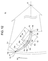
- FIG. 11 to FIG. 13 are views for illustrating a blade shape in a cross section taken along the line A-A in FIG. 3 .
- the outer peripheral end portion 15a and the inner peripheral end portion 15b of the blade 8c are each formed into an arc shape. Further, the blade 8c is formed so that the outer peripheral endportion 15a side is inclined forward in the impeller rotational direction RO with respect to the inner peripheral end portion 15b side. That is, when the blade 8c is viewed in the vertical cross section, a blade pressure surface 13a and a blade suction surface 13b of the blade 8c are curved in the impeller rotational direction RO as approaching from the impeller rotation center (rotational axis) O of the impeller 8a toward the outer side of the blade 8c.
- a center of a circle corresponding to the arc shape formed in the outer peripheral end portion 15a is represented by P1 (also referred to as “arc center P1"), and a center of a circle corresponding to the arc shape formed in the inner peripheral end portion 15b is represented by P2 (also referred to as “arc center P2").
- P1 also referred to as "arc center P1”
- P2 also referred to as "arc center P2”
- a line segment connecting together the arc centers P1 and P2 is represented by a blade chord line (blade chord) L, as illustrated inFIG. 13, the length of the blade chord line L is set to Lo (hereinafter also referred to as "blade chord length Lo").
- the blade 8c includes the blade pressure surface 13a, which is a surface on the rotational direction RO side of the impeller 8a, and the blade suction surface 13b, which is a surface on an opposite side to the rotational direction RO side of the impeller 8a.
- the blade 8c In the vicinity of the center of the blade chord line L, the blade 8c has a concave shape curved in a direction from the blade pressure surface 13a toward the blade suction surface 13b.
- a radius of a circle corresponding to the arc shape on the blade pressure surface 13a side is different between the outer peripheral side of the impeller 8a and the inner peripheral side of the impeller 8a. That is, as illustrated in FIG. 12 , the surface of the blade 8c on the blade pressure surface 13a side is a multiple-arc curved surface and includes an outer peripheral curved surface Bp1 in which a radius (arc radius) corresponding to the arc shape on the outer peripheral side of the impeller 8a is Rp1, and an inner peripheral curved surface Bp2 in which a radius (arc radius) corresponding to the arc shape on the inner peripheral side of the impeller 8a is Rp2. Further, the surface of the blade 8c on the blade pressure surface 13a side includes a flat surface Qp having a planar shape, which is connected to an inner peripheral end portion of the end portions of the inner peripheral curved surface Bp2.
- the surface of the blade 8c on the blade pressure surface 13a side is formed in a manner that the outer peripheral curved surface Bp1, the inner peripheral curved surface Bp2, and the flat surface Qp are continuously connected to one another. Note that, when the blade 8c is viewed in the vertical cross section, the straight line forming the flat surface Qp is a tangent at a point connected to the arc forming the inner peripheral curved surface Bp2.
- the surface of the blade 8c on the blade suction surface 13b side is a surface corresponding to the surface on the blade pressure surface 13a side.
- the surface of the blade 8c on the blade suction surface 13b side includes an outer peripheral curved surface Bs1 in which a radius (arc radius) corresponding to the arc shape on the outer peripheral side of the impeller 8a is Rs1, and an inner peripheral curved surface Bs2 in which a radius (arc radius) corresponding to the arc shape on the inner peripheral side of the impeller 8a is Rs2.
- the surface of the blade 8c on the blade suction surface 13b side includes a flat surface Qs having a planar shape, which is connected to an inner peripheral end portion of the end portions of the inner peripheral curved surface Bs2.
- the surface of the blade 8c on the blade suction surface 13b side is formed in a manner that the outer peripheral curved surface Bs1, the inner peripheral curved surface Bs2, and the flat surface Qs are continuously connected to one another. Note that, when the blade 8c is viewed in the vertical cross section, the straight line forming the flat surface Qs is a tangent at a point connected to the arc forming the inner peripheral curved surface Bs2.
- a blade thickness (thickness) t1 at the outer peripheral end portion 15a is smaller than a blade thickness (thickness) t2 at the inner peripheral end portion 15b.
- the blade thickness t1 corresponds to 2 ⁇ radius R1 of the circle forming the arc of the outer peripheral end portion 15a
- the blade thickness t2 corresponds to 2 ⁇ radius R2 of the circle forming the arc of the inner peripheral end portion 15b.
- the blade thickness is formed as follows.
- the blade thickness of the outer peripheral end portion 15a is smaller than that of the inner peripheral end portion 15b, and the blade thickness gradually increases as approaching from the outer peripheral end portion 15a toward the center to become maximum at a predetermined position in the vicinity of the center. Then, the blade thickness gradually decreases as approaching toward the inner side to become substantially the same thickness at a straight portion Q.
- the blade thickness t of the blade 8c gradually increases as approaching from the outer peripheral end portion 15a toward the center of the blade 8c, becomes a maximum thickness t3 at the predetermined position in the vicinity of the center of the blade chord line L, and gradually decreases as approaching toward the inner peripheral end portion 15b.
- the blade thickness t is the inner peripheral end portion thickness t2 that is a substantially constant value.
- the blade suction surface 13b of the blade 8c is formed of the multiple arcs and the straight portion Q in a range from the outer peripheral side toward the inner peripheral side of the impeller.
- the cross-flow fan having the above-mentioned configuration and the air conditioner having the cross-flow fan mounted thereon can achieve the following effects.
- each of the plurality of blades 8c has an outer diameter and an inner diameter that are identical in the rotational axis direction, and has a cross-sectional shape and a blade outlet angle that are identical over the rotational axis direction. Further, each of the plurality of blades 8c includes at least one region that is advanced or retreated in the rotational direction over the rotational axis direction, and has at least two different blade outlet angles.
- each blade that are inclined in the rotation axis direction in a plurality of modes and are also inclined in the rotational direction in a plurality of modes are successively and repetitively blown out.
- the flows are blown out uniformly between the pair of rings, and an extremely uniform blowing-out distribution can be obtained as a successive flow state resulting from the rotation of the cross-flow fan.
- the flow can be suitably dispersed over the rotational axis direction in the entire fan.
- FIG. 14 is a view for illustrating the second embodiment of the present invention in the same manner as in FIG. 3
- FIG. 15 is a view for illustrating a blade shape in a cross section taken along the line B-B in FIG. 14 .
- the configuration in the second embodiment is the same as that in the above-mentioned first embodiment except for portions to be described below.
- each of a plurality of blades 108c has an outer diameter and an inner diameter that are identical in the rotational axis direction, and only includes a region that is advanced or retreated in the rotational direction between a pair of rings.
- the blade portion on one ring side is deviated from the blade portion on the other ring side by an angle ⁇ .
- the second embodiment configured as described above can also achieve the same effects as in the first embodiment.
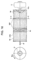
- FIG. 16 is a view for illustrating the third embodiment of the present invention in the same manner as in FIG. 3
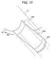
- FIG. 17 is a view for illustrating the third embodiment of the present invention in the same manner as in FIG. 4
- FIG. 18 is a view for illustrating a blade shape in a cross section taken along the line C-C in FIG. 16 .
- the configuration in the third embodiment is the same as that in the above-mentioned first embodiment except for portions to be described below.
- each of a plurality of blades 208c has an outer diameter and an inner diameter that are identical in the rotational axis direction, and includes only a region that is advanced in the rotational direction between a pair of rings or a region that is retreated in the rotational direction between the pair of rings, and a pair of ring-side portions 220 that are positioned on both sides of the above-mentioned region and extend along the rotational axis direction without being advanced or retreated in the rotational direction, respectively.
- the portion on one ring side is deviated from the portion on the other ring side by the angle ⁇ .
- each of the plurality of blades achieves the following advantages due to the pair of ring-side portions that extend along the rotational axis direction without being advanced or retreated in the rotational direction.
- the plurality of impeller elements are stacked together and blades of one impeller element are welded to the ring of another stacked impeller element, the blade tips are upright and hence come into contact with the ring surface in an upright state. Accordingly, the weldability is improved while achieving good assembling workability.
- the blade parallel portions (ring-side portions) at both ends have no inclination to suppress concentration or dispersion of the flow on or from the ring surface, thus stabilizing the flow in the vicinity of the ring.
- a uniform airflow velocity distribution can be achieved and back flow can be prevented from occurring even when dust and the like are deposited on the filter installed at the air inlet of the air conditioner to increase the pressure loss. Therefore, a high-quality air conditioner causing no dew condensation also during the cooling can be obtained.
- the above-mentioned first embodiment may also be carried out by reversing the relationship of advance and retreat in each portion and using a blade formed into a V-shape instead of the inverted V-shape.
Landscapes
- Engineering & Computer Science (AREA)
- Mechanical Engineering (AREA)
- General Engineering & Computer Science (AREA)
- Structures Of Non-Positive Displacement Pumps (AREA)
Applications Claiming Priority (2)
| Application Number | Priority Date | Filing Date | Title |
|---|---|---|---|
| PCT/JP2013/079215 WO2015063850A1 (fr) | 2013-10-29 | 2013-10-29 | Ventilateur tangentiel et climatiseur |
| PCT/JP2014/078719 WO2015064617A1 (fr) | 2013-10-29 | 2014-10-29 | Ventilateur à flux transversal et climatiseur |
Publications (2)
| Publication Number | Publication Date |
|---|---|
| EP3064777A1 true EP3064777A1 (fr) | 2016-09-07 |
| EP3064777A4 EP3064777A4 (fr) | 2017-07-19 |
Family
ID=53003501
Family Applications (1)
| Application Number | Title | Priority Date | Filing Date |
|---|---|---|---|
| EP14859194.4A Withdrawn EP3064777A4 (fr) | 2013-10-29 | 2014-10-29 | Ventilateur à flux transversal et climatiseur |
Country Status (3)
| Country | Link |
|---|---|
| EP (1) | EP3064777A4 (fr) |
| JP (1) | JPWO2015064617A1 (fr) |
| WO (2) | WO2015063850A1 (fr) |
Families Citing this family (3)
| Publication number | Priority date | Publication date | Assignee | Title |
|---|---|---|---|---|
| CN108194386A (zh) * | 2018-02-07 | 2018-06-22 | 广东纽恩泰新能源科技发展有限公司 | 一种贯流式风机 |
| CN108758825A (zh) * | 2018-07-27 | 2018-11-06 | 青岛海尔空调器有限总公司 | 壁挂式空调室内机 |
| JP2025086648A (ja) * | 2023-11-28 | 2025-06-09 | ダイキン工業株式会社 | クロスフローファン及び空気調和機 |
Family Cites Families (11)
| Publication number | Priority date | Publication date | Assignee | Title |
|---|---|---|---|---|
| JPS61144294U (fr) * | 1985-02-28 | 1986-09-05 | ||
| JP3107711B2 (ja) | 1994-08-09 | 2000-11-13 | 株式会社東芝 | 横流ファン |
| JPH09158890A (ja) | 1995-12-08 | 1997-06-17 | Fujitsu General Ltd | 空気調和機 |
| JP3137897B2 (ja) * | 1996-03-12 | 2001-02-26 | 株式会社日立製作所 | 貫流ファン |
| CN1603631A (zh) * | 2004-10-29 | 2005-04-06 | 吴劲松 | 斜式干涉降噪型离心风机 |
| KR101436628B1 (ko) * | 2007-10-23 | 2014-09-02 | 엘지전자 주식회사 | 횡류팬 및 공기 조화기 |
| JP4549416B2 (ja) | 2008-10-22 | 2010-09-22 | シャープ株式会社 | 貫流ファン、送風機および羽根車の成形機 |
| JP4896213B2 (ja) * | 2009-12-10 | 2012-03-14 | 三菱電機株式会社 | 貫流ファン及びこれを備えた空気調和機 |
| KR101649379B1 (ko) * | 2010-01-13 | 2016-08-30 | 엘지전자 주식회사 | 횡류팬 및 이를 구비한 공기 조화기 |
| JP5369141B2 (ja) * | 2011-06-10 | 2013-12-18 | 三菱電機株式会社 | 空気調和機 |
| JP5143317B1 (ja) * | 2012-04-06 | 2013-02-13 | 三菱電機株式会社 | 空気調和装置の室内機 |
-
2013
- 2013-10-29 WO PCT/JP2013/079215 patent/WO2015063850A1/fr not_active Ceased
-
2014
- 2014-10-29 WO PCT/JP2014/078719 patent/WO2015064617A1/fr not_active Ceased
- 2014-10-29 EP EP14859194.4A patent/EP3064777A4/fr not_active Withdrawn
- 2014-10-29 JP JP2015545256A patent/JPWO2015064617A1/ja active Pending
Also Published As
| Publication number | Publication date |
|---|---|
| WO2015063850A1 (fr) | 2015-05-07 |
| WO2015064617A1 (fr) | 2015-05-07 |
| EP3064777A4 (fr) | 2017-07-19 |
| JPWO2015064617A1 (ja) | 2017-03-09 |
Similar Documents
| Publication | Publication Date | Title |
|---|---|---|
| US9995303B2 (en) | Air conditioner | |
| US10436496B2 (en) | Indoor unit for air-conditioning apparatus | |
| CN103089661B (zh) | 横流风扇 | |
| US9995504B2 (en) | Air conditioner having air outlet louver with varying curvature | |
| CN106481574B (zh) | 离心式风机和包括其的空调机 | |
| EP3064777A1 (fr) | Ventilateur à flux transversal et climatiseur | |
| CN109983282B (zh) | 空调装置的室内机组 | |
| EP3064776B1 (fr) | Ventilateur tangentiel et climatiseur | |
| JP6000454B2 (ja) | 空気調和装置の室内機 | |
| JPWO2013150673A1 (ja) | 空気調和装置の室内機 | |
| WO2023089658A1 (fr) | Ventilateur tangentiel | |
| WO2023223383A1 (fr) | Ventilateur à flux transversal, dispositif de soufflage, et dispositif à cycle de réfrigération | |
| WO2018042487A1 (fr) | Soufflante, et unité intérieure pour dispositif de climatisation | |
| NZ700985B2 (en) | Indoor unit for air conditioning device | |
| NZ716887B2 (en) | Indoor unit for air-conditioning apparatus |
Legal Events
| Date | Code | Title | Description |
|---|---|---|---|
| PUAI | Public reference made under article 153(3) epc to a published international application that has entered the european phase |
Free format text: ORIGINAL CODE: 0009012 |
|
| 17P | Request for examination filed |
Effective date: 20160526 |
|
| AK | Designated contracting states |
Kind code of ref document: A1 Designated state(s): AL AT BE BG CH CY CZ DE DK EE ES FI FR GB GR HR HU IE IS IT LI LT LU LV MC MK MT NL NO PL PT RO RS SE SI SK SM TR |
|
| AX | Request for extension of the european patent |
Extension state: BA ME |
|
| DAX | Request for extension of the european patent (deleted) | ||
| A4 | Supplementary search report drawn up and despatched |
Effective date: 20170619 |
|
| RIC1 | Information provided on ipc code assigned before grant |
Ipc: F04D 17/04 20060101AFI20170612BHEP Ipc: F04D 29/28 20060101ALI20170612BHEP |
|
| STAA | Information on the status of an ep patent application or granted ep patent |
Free format text: STATUS: THE APPLICATION IS DEEMED TO BE WITHDRAWN |
|
| 18D | Application deemed to be withdrawn |
Effective date: 20180117 |