EP3064793A1 - Système de capteur de mouvement pour véhicules sur rail - Google Patents
Système de capteur de mouvement pour véhicules sur rail Download PDFInfo
- Publication number
- EP3064793A1 EP3064793A1 EP15157369.8A EP15157369A EP3064793A1 EP 3064793 A1 EP3064793 A1 EP 3064793A1 EP 15157369 A EP15157369 A EP 15157369A EP 3064793 A1 EP3064793 A1 EP 3064793A1
- Authority
- EP
- European Patent Office
- Prior art keywords
- motion sensor
- shaft
- sensor system
- rotary motion
- axle
- Prior art date
- Legal status (The legal status is an assumption and is not a legal conclusion. Google has not performed a legal analysis and makes no representation as to the accuracy of the status listed.)
- Withdrawn
Links
- 230000033001 locomotion Effects 0.000 title claims abstract description 219
- 230000008878 coupling Effects 0.000 claims abstract description 33
- 238000010168 coupling process Methods 0.000 claims abstract description 33
- 238000005859 coupling reaction Methods 0.000 claims abstract description 33
- 238000005096 rolling process Methods 0.000 claims description 6
- 238000001514 detection method Methods 0.000 abstract description 3
- 210000002105 tongue Anatomy 0.000 description 9
- 238000003860 storage Methods 0.000 description 6
- 230000005540 biological transmission Effects 0.000 description 4
- 238000011156 evaluation Methods 0.000 description 3
- 238000007373 indentation Methods 0.000 description 2
- 238000005299 abrasion Methods 0.000 description 1
- 238000005520 cutting process Methods 0.000 description 1
- 230000000694 effects Effects 0.000 description 1
- 230000001771 impaired effect Effects 0.000 description 1
- 230000003993 interaction Effects 0.000 description 1
- 230000003287 optical effect Effects 0.000 description 1
- 238000003825 pressing Methods 0.000 description 1
- 238000010079 rubber tapping Methods 0.000 description 1
- 238000009987 spinning Methods 0.000 description 1
Images






Classifications
-
- G—PHYSICS
- G01—MEASURING; TESTING
- G01P—MEASURING LINEAR OR ANGULAR SPEED, ACCELERATION, DECELERATION, OR SHOCK; INDICATING PRESENCE, ABSENCE, OR DIRECTION, OF MOVEMENT
- G01P1/00—Details of instruments
- G01P1/04—Special adaptations of driving means
-
- B—PERFORMING OPERATIONS; TRANSPORTING
- B61—RAILWAYS
- B61L—GUIDING RAILWAY TRAFFIC; ENSURING THE SAFETY OF RAILWAY TRAFFIC
- B61L25/00—Recording or indicating positions or identities of vehicles or trains or setting of track apparatus
- B61L25/02—Indicating or recording positions or identities of vehicles or trains
- B61L25/021—Measuring and recording of train speed
-
- F—MECHANICAL ENGINEERING; LIGHTING; HEATING; WEAPONS; BLASTING
- F16—ENGINEERING ELEMENTS AND UNITS; GENERAL MEASURES FOR PRODUCING AND MAINTAINING EFFECTIVE FUNCTIONING OF MACHINES OR INSTALLATIONS; THERMAL INSULATION IN GENERAL
- F16D—COUPLINGS FOR TRANSMITTING ROTATION; CLUTCHES; BRAKES
- F16D1/00—Couplings for rigidly connecting two coaxial shafts or other movable machine elements
- F16D1/06—Couplings for rigidly connecting two coaxial shafts or other movable machine elements for attachment of a member on a shaft or on a shaft-end
-
- G—PHYSICS
- G01—MEASURING; TESTING
- G01P—MEASURING LINEAR OR ANGULAR SPEED, ACCELERATION, DECELERATION, OR SHOCK; INDICATING PRESENCE, ABSENCE, OR DIRECTION, OF MOVEMENT
- G01P1/00—Details of instruments
- G01P1/02—Housings
- G01P1/026—Housings for speed measuring devices, e.g. pulse generator
-
- G—PHYSICS
- G01—MEASURING; TESTING
- G01P—MEASURING LINEAR OR ANGULAR SPEED, ACCELERATION, DECELERATION, OR SHOCK; INDICATING PRESENCE, ABSENCE, OR DIRECTION, OF MOVEMENT
- G01P3/00—Measuring linear or angular speed; Measuring differences of linear or angular speeds
- G01P3/42—Devices characterised by the use of electric or magnetic means
- G01P3/44—Devices characterised by the use of electric or magnetic means for measuring angular speed
- G01P3/48—Devices characterised by the use of electric or magnetic means for measuring angular speed by measuring frequency of generated current or voltage
- G01P3/481—Devices characterised by the use of electric or magnetic means for measuring angular speed by measuring frequency of generated current or voltage of pulse signals
-
- F—MECHANICAL ENGINEERING; LIGHTING; HEATING; WEAPONS; BLASTING
- F16—ENGINEERING ELEMENTS AND UNITS; GENERAL MEASURES FOR PRODUCING AND MAINTAINING EFFECTIVE FUNCTIONING OF MACHINES OR INSTALLATIONS; THERMAL INSULATION IN GENERAL
- F16D—COUPLINGS FOR TRANSMITTING ROTATION; CLUTCHES; BRAKES
- F16D2300/00—Special features for couplings or clutches
- F16D2300/18—Sensors; Details or arrangements thereof
-
- G—PHYSICS
- G01—MEASURING; TESTING
- G01D—MEASURING NOT SPECIALLY ADAPTED FOR A SPECIFIC VARIABLE; ARRANGEMENTS FOR MEASURING TWO OR MORE VARIABLES NOT COVERED IN A SINGLE OTHER SUBCLASS; TARIFF METERING APPARATUS; MEASURING OR TESTING NOT OTHERWISE PROVIDED FOR
- G01D5/00—Mechanical means for transferring the output of a sensing member; Means for converting the output of a sensing member to another variable where the form or nature of the sensing member does not constrain the means for converting; Transducers not specially adapted for a specific variable
- G01D5/26—Mechanical means for transferring the output of a sensing member; Means for converting the output of a sensing member to another variable where the form or nature of the sensing member does not constrain the means for converting; Transducers not specially adapted for a specific variable characterised by optical transfer means, i.e. using infrared, visible, or ultraviolet light
- G01D5/32—Mechanical means for transferring the output of a sensing member; Means for converting the output of a sensing member to another variable where the form or nature of the sensing member does not constrain the means for converting; Transducers not specially adapted for a specific variable characterised by optical transfer means, i.e. using infrared, visible, or ultraviolet light with attenuation or whole or partial obturation of beams of light
- G01D5/34—Mechanical means for transferring the output of a sensing member; Means for converting the output of a sensing member to another variable where the form or nature of the sensing member does not constrain the means for converting; Transducers not specially adapted for a specific variable characterised by optical transfer means, i.e. using infrared, visible, or ultraviolet light with attenuation or whole or partial obturation of beams of light the beams of light being detected by photocells
- G01D5/347—Mechanical means for transferring the output of a sensing member; Means for converting the output of a sensing member to another variable where the form or nature of the sensing member does not constrain the means for converting; Transducers not specially adapted for a specific variable characterised by optical transfer means, i.e. using infrared, visible, or ultraviolet light with attenuation or whole or partial obturation of beams of light the beams of light being detected by photocells using displacement encoding scales
- G01D5/3473—Circular or rotary encoders
- G01D5/34738—Axles; Driving or coupling means
Definitions
- the invention relates to a motion sensor system for mounting on the axle of a rail vehicle, comprising at least one first shaft rotatable by the axis of the rail vehicle and having at least one dimensional standard of a first rotation sensor rotatably connected to the first shaft, wherein the first shaft is an output element for tapping the movement of Has axis.
- the invention also relates to an axle for a rail vehicle.
- Motion sensor systems are important components of modern rail vehicles. Motion sensor systems can be used to detect, analyze, and control rotations of the axles of rail vehicles.
- Known rotational motion sensors are often mounted to stationary parts of the rail vehicle such that the axle of the rail vehicle can transmit its rotational motion to the shaft of the rotary motion sensor.
- a disadvantage of the known rotational motion sensors is that they can often only provide information about individual parameters of the rotational movement of the axle of the rail vehicle.
- known rotational motion sensors have a large volume.
- This object is achieved according to the invention for a motion sensor system of the type mentioned above in that the first shaft is designed to transmit a torque to a second rotary motion sensor.
- a motion sensor system can be formed from two rotational motion sensors, of which each rotational motion sensor can each be designed to detect different parameters. Since a second rotation sensor gets the torque transmitted from the first shaft, the motion sensor system can be made very compact and also be attached to one end of the axle of the rail vehicle. This means that different parameters can be tapped at one axis end.
- the rotational motion sensors mentioned can each consist of an associated material measure and at least one associated query element.
- the rotational motion sensors may include sensor components such as evaluation or control units.
- the transmission of the torque or the rotational movement to the second rotary motion sensor can take place at one end of the first shaft, which lies in the axial direction of the shaft relative to the output element.
- the object according to the invention is achieved in that the axle has an inventive motion sensor system at one axle end.
- the axle of the rail vehicle only has to be configured at one axle end for transmitting its torque to a motion sensor system. This can save costs.
- the output element may be formed by a located on an axle-side end of the first shaft driver member.
- the driver member may be configured to pick up the movement of the axle of the rail vehicle and transfer it to the shaft.
- the cam member may be engaged with a drive member of the axle of the rail vehicle when the motion sensor system is mounted on the axle.
- the driver member may be formed in particular by a driver disk, wherein a disk plane is arranged perpendicular to the shaft axis.
- the entrainment member may be crimped with the axle-side end of the first shaft.
- This type of connection is also inexpensive to produce.
- the entrainment member in particular a drive plate, can for this purpose have a receiving opening, through which the shaft protrudes in the compressed state.
- the driver member is formed by a driver disk, the driver disk preferably has a receiving opening for the shaft in its center.
- the shaft can be used to back up the Mit Studentsorgans have at their achseititigen end a shaft head whose diameter is greater than a diameter of the receiving opening of the driver member.
- the safe, torsionally rigid connection between the first shaft and the output element or the drive plate is particularly important if the motion sensor system has two rotational motion sensors, since both rotational motion sensors pick up the rotation of the axis of the rail vehicle via the output element of the first shaft.
- the output element may have a receiving opening for the first shaft with at least one bulge for at least one positive-locking element.
- the output member or a drive member forming the output member is crimped with the axle end of the first shaft, located in the bulge positive locking element of the first shaft can ensure that the rotational movement of the output element is also transmitted to the shaft when the press connection between the output element and the first shaft should be loosened or loosened.
- the output element is formed by a driver disk
- the at least one projection preferably extends radially from the receiving opening for the first shaft into the driver disk.
- the output element preferably has two bulges lying opposite one another, which together can form an elongate receptacle for an elongate positive-locking element.
- the form-fitting element may in particular be pin-shaped.
- the positive-locking element preferably projects on the axle-side shaft end through the first shaft. Alternatively, it may also be formed monolithically with the first shaft or attached externally to this. So that the interlocking element can protrude through the first shaft, the first shaft can have a continuous opening for the interlocking element transversely to the shaft axis. The continuous opening for the interlocking element preferably extends through the axial center of the first shaft.
- the bulge for the at least one interlocking element in the driven element preferably extends parallel to the axial direction of the shaft through the driven element.
- the at least one bulge thus extends axially through the drive plate and radially into it.
- the continuous opening for the positive-locking element in the first shaft preferably adjoins the head on the axle-side shaft end.
- the continuous opening can be extend at least partially through the head.
- the opening for the positive-locking element does not necessarily have to be a continuous opening.
- the first shaft may also have one or more openings, which extend radially into the shaft end, to receive in each case a positive-locking element.
- an elongate positive locking element is first inserted into the continuous opening and then the driven element, which is preferably formed by a drive plate, pressed onto the shaft until the output element rests against the head of the shaft and while the positive-locking element is received in the at least one bulge.
- the output element in particular a drive plate can be arranged for particularly secure attachment alternatively or additionally to the previously described connection with the form-fitting element between the head of the shaft and a ball bearing inner ring of the first rotation sensor.
- a train can be exerted on the shaft by a suitable fastening measure in the first rotary motion sensor, so that the drive plate is pressed between the head of the shaft and said ball bearing inner ring.
- the drive plate can be rotatable about the shaft axis.
- the output member may comprise at least one receiving slot extending transversely to the shaft axis for receiving a drive element of the axis of the rail vehicle, wherein the at least one receiving slot is bounded on at least one side by an elastically deflectable tongue.
- the receiving slot can be selected so that its receiving diameter corresponds at most to the diameter of the drive element.
- the receiving slot without a drive element received in it has a receiving diameter, which is smaller than a diameter of the drive element.
- the first shaft with at least one further material measure of the be provided second rotary motion sensor transmits the torque or the rotational movement of the axis of the rail vehicle by this measure directly to at least one material measure of the second rotational movement sensor.
- the first shaft may have a first coupling part for the torsionally rigid connection with a second coupling part of a shaft of the second rotary motion sensor.
- the motion sensor system can be modular. This may be advantageous for making the first shaft of the first rotation sensor and the shaft of the second rotation sensor separate from each other. Another advantage may be that a motion sensor system is first mounted on an axle of the rail vehicle only with a first rotational motion sensor as long as only the parameters detected by that first rotary motion sensor are to be recorded. If further parameters are to be detected at a later time, a shaft of the second rotational motion sensor can be attached via the coupling to the first shaft of the first rotational motion sensor, so that the motion sensor system can use two rotational motion sensors.
- the coupling between the first coupling part and the second coupling part is preferably form-fitting.
- the first coupling part can engage with the second coupling part in a coupled state.
- a coupling between the first coupling part and the second coupling part can also be frictional or magnetic.
- the first coupling part with the second coupling part along the axial direction of the first shaft can be pushed together or plugged together.
- the first rotation sensor may be formed by an incremental encoder.
- An incremental encoder can be used to determine the rotational speed of the axis of the rail vehicle with high accuracy.
- the incremental rotary encoder can be designed to output a rolling signal. Rolling signals can provide information about a rolling of the axle, which should be avoided. An incremental encoder which can output a rolling signal can be essential for the safe operation of a rail vehicle.
- the measuring graduation of the first rotary motion sensor can be formed by an incremental disk.
- the incremental disc can be arranged in particular rotationally fixed on the first shaft.
- the incremental disk can be pressed onto the first shaft and / or can be positively connected to the first shaft by pinning.
- the second rotation sensor may be constituted by a device for detecting rotation of the axis of the rail vehicle in a de-energized state of the rail vehicle.
- the second rotary motion sensor may be a cold movement detector (CMD). With this it is possible to detect a rotation of the axis of the rail vehicle, even if the rail vehicle is in a disarmed and therefore de-energized state.
- CMD cold movement detector
- a motion sensor system in which the first rotary motion sensor is an incremental rotary encoder, in particular one with integrated roller burn detection, and the second rotary motion sensor is a cold movement detector, is particularly advantageous since important safety-relevant parameters can be detected with such a motion sensor system.
- the first rotary motion sensor may sense the speed of the axle and any rolling thereof, and the second rotary motion sensor may serve to detect movement of the axle in a de-energized state of the rail vehicle. Since the two rotary motion sensors form a motion sensor system and can be arranged at an axle end of the rail vehicle, a compact motion sensor system is provided, by means of which it is possible to generate the aforementioned parameters at an axle end.
- the second rotation sensor may be configured to detect a movement of the axis of the rail vehicle, even if the second rotation sensor itself is de-energized.
- the dimensional standard of the second rotary motion sensor is formed by a cam disk and the second rotary motion sensor has bistable actuators which can be displaced from a state to a second state by the cam disk upon rotation of the shaft. This can also be done in the de-energized state of the rotary motion sensor itself, wherein the state of the actuators can be read by an evaluation unit as soon as at least the second rotary motion sensor is again connected to a voltage source.
- At least one dimensional standard of the second rotational motion sensor can be arranged on the first shaft.
- the first shaft may constitute a common shaft for the first and second rotational motion sensors.
- at least one material measure of the second rotation sensor it is also possible for at least one material measure of the second rotation sensor to be arranged on the first shaft, but this shaft is nevertheless connected via a coupling to a second shaft, on which at least one further dimensional standard of the second rotation sensor is arranged.
- a rotary motion sensor In a mounted state, a rotary motion sensor can each be arranged at least in sections in an associated housing part. As a result, the individual rotary motion sensors can be protected against external influences in accordance with their dimensions and technical requirements. It is particularly advantageous if the housing parts can be assembled to form a common system housing of the motion sensor system. It is also advantageous if the housing parts can be assembled parallel to the axial direction of the first shaft of the first rotary motion sensor.
- a housing part of the second rotary motion sensor on the housing part of the first rotary motion sensor and simultaneously to connect a second shaft of the second rotary motion sensor to the first shaft of the first rotary motion sensor, or the first shaft of the rotary motion sensor to a material measure of the second rotary motion sensor to insert into the housing part of the second rotation sensor.
- At least one rotary motion sensor with its associated housing part form an exchangeable sensor module.
- each sensor module has a rotary motion sensor and the associated housing part.
- the exchangeable sensor modules each have their own shafts with coupling parts, so that by a connection of two sensor modules and the waves of the rotary motion sensors are rotatably connected to each other.
- the shafts can each be mounted in their sensor modules or in their housing parts, ie each shaft has an integral bearing.
- only the first wave can be used have a self-storage.
- the shaft of the second rotary motion sensor can be configured without own storage and use as an extension of the first wave their storage.
- each rotary motion sensor may have its own data line for transmitting sensor signals to at least one control device.
- the control device can either be a component of the motion sensor system, or represent an external system.
- each housing part may have at least one connection for a data line of the associated rotational motion sensor.
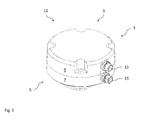
- Fig. 1 shows a movement sensor system 1 according to the invention in a perspective view.
- the first embodiment of the motion sensor system 1 has a first rotation sensor 3 and a second rotation sensor 5.
- the first rotation sensor 3 may have an associated housing part 7 and the second rotation sensor 5 may have an associated housing part 9.
- the housing parts 7 and 9 form a system housing 11.
- the housing part 9 of the second rotary motion sensor 5 may be designed lid-like.
- the housing part 7 has a terminal 13 for a data line (not shown) of the first rotation sensor 3, and the housing part 9 has a terminal 15 for a data line of the second rotary motion sensor 5.
- the separate terminals 13 and 15 allow the data of the rotary motion sensors 3 and 5 to be routed separately from the system housing 11.
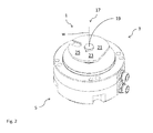
- Fig. 2 shows the motion sensor system 1 Fig. 1 with a view to an axle-side end 17 of a first shaft 19 of the first rotary motion sensor 3.
- the first shaft 19 projects out of the housing part 7 of the first rotary motion sensor 3.
- the first shaft 19 is rotatable about the shaft axis W.
- Rotationally connected to the first shaft 19 is the driven element 21.
- the driven element 21 is used for picking up the rotational movement of the axis of a rail vehicle.
- the axle of the rail vehicle (not shown) may have a drive element which can transmit the movement of the axle to the driven element 21.
- the output element 21 is preferably formed by a driver member 23.
- the output member 21 may be, for example, a part of a transmission, a pickup for a belt or a gear.
- the output element 21 may be formed by any element which is suitable for driving through the axis of the rail vehicle or arranged on the axis of the rail vehicle drive element.
- the driver member 23 is preferably formed as a drive plate 25.
- the driven element 21 or the driver element 23 can be both compact and dimensionally stable at the same time.
- driver members 23 is with reference to the Figures 13 and 14 discussed in more detail.
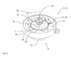
- Fig. 3 shows the first rotation sensor 3 of FIG FIGS. 1 and 2 described first embodiment of the motion sensor system 1 according to the invention without the cover-like housing part 9 of the second rotary motion sensor 5.
- the first shaft 19 protrudes through the first rotary motion sensor 3 and through its associated housing part 7 therethrough.
- the first shaft 19 is rotatably supported in the first rotation sensor 3.
- the first rotary motion sensor 3 can have at least one bearing, in particular a ball bearing.
- a material measure 27 of the first rotation sensor 3 is rotatably arranged on the first shaft 19, a material measure 27 of the first rotation sensor 3 is rotatably arranged.
- the material measure 27 extends radially about the shaft axis W of the first shaft 19.
- the material measure 27 of the first rotation sensor 3 is formed by an incremental disk 29.
- the configuration of the first rotary motion sensor 3 as an incremental rotary encoder 31 is a preferred embodiment of the invention.
- the first rotation sensor 3 may be formed by another rotation sensor.
- the measuring graduation 27 of the first rotary motion sensor 3 need not necessarily be formed by an incremental disk 29.
- sensor components 33 may be housed, which are configured for interrogation and evaluation of the material measure 27.
- the sensor components 33 may be optical detection systems for evaluating the increments of the incremental disk 29.
- the first shaft 19 may be designed so that it projects beyond an upper edge 35 of the housing part 7 also.
- the upper edge 35 is arranged in the direction of the shaft axis W opposite the axle-side end 17.
- the first shaft 19 thus extends beyond the measuring graduation 27 of the first rotary motion sensor 3 at its end opposite the axle-side end 17.
- the first shaft 19 may have at least one further measuring standard 39 of the second rotary motion sensor 5.
- the upper portion 37 of the first shaft 19 has three further measuring graduations 39.
- the further dimensional standards 39 are rotatably connected to the first shaft 19.
- the further measuring graduations 39 of the second rotary motion sensor 5 therefore rotate with the shaft 19 of the first rotary motion sensor 3.
- the torque of the first shaft 19 can be transmitted directly to the measuring graduations 39 of the second rotary motion sensor 5.
- the second rotation sensor 5 is formed according to a preferred embodiment of the invention by a device 41 for detecting rotation in a de-energized state of the rail vehicle.
- the device 41 may be a so-called Cold Movement Detector (CMD).
- CMD Cold Movement Detector
- At least one further measuring standard 39 of the second rotary motion sensor 5 may be formed by a cam disk 43.
- the second rotational movement sensor 5 has three further measuring embodiments 39 formed as a cam disc 43.
- the cams 43 may be crimped and / or pinned to the first shaft 19.
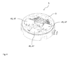
- Fig. 4 shows an interior view of the associated housing part 9 of the second rotational movement sensor 5 of the first embodiment.
- the associated housing part 9 can be designed such that it can be positively inserted into the associated housing part 7 of the first rotary motion sensor 3.
- query elements 45 of the second rotary motion sensor 5 may be arranged.
- the query elements 45 are configured such that they can interrogate or evaluate the material measures 39. If the second rotary motion sensor 5 is a device 41 or a CMD as described, the interrogation elements 45 are preferably formed by bistable actuators 47, which can be deflected by the cams 43, so that rotation of the first shaft 19 can be detected.
- the second rotation sensor 5 is designed so that it can detect a rotational movement of the first shaft 19 when it is not connected to any voltage source. This can be done by an interaction of the cams 43 with the bistable actuators 47. Each cam 43 is associated with a bistable actuator 47. Upon rotation of the first shaft 19, whereby the cams 43 are also rotated, at least one of the cams 43 can move its associated bistable actuator 47 from a first state to a second state. This state can later, as soon as the second rotary motion sensor 5 and / or the rail vehicle are powered again, be read out and compared with a value stored before switching off.
- Fig. 5 and 6 show a second embodiment of a motion sensor system according to the invention 1.
- the housing part 7 of the first rotation sensor 3 has the sensor components 33 of the first rotation sensor 3 and the first shaft 19.
- the first shaft 19 of the second embodiment has no further measuring standard 39 of the second rotary motion sensor 5.
- the first shaft 19 has a first coupling part 49, which is arranged at its end opposite the axle-side end 17.
- the material measure 27 of the first rotary motion sensor 3 extends around the first coupling part 49.
- the first coupling part 49 formed as a parallel to the shaft axis W in the first shaft 19 extending into square-shaped receptacle 51 for receiving a complementarily formed counterpart 53 of the second rotational movement sensor 5.
- the counterpart 53 is part of a shaft 55 of the second rotary motion sensor 5 or connected to a shaft 55 of the second rotary motion sensor 5.
- the counterpart 53 represents the second coupling part 57 of the second rotary motion sensor 5.
- the invention is not limited to the illustrated square shape of the coupling parts 49 and 57. There are also other for the torsionally rigid connection of the first shaft 19 with the second shaft 55 suitable embodiments conceivable.
- the shaft 55 of the second rotary motion sensor 5 may have its own storage 59.
- the bearing 59 may consist of at least one ball bearing.
- the bearing 59 has two ball bearings spaced apart along the shaft axis W, at least one further measuring standard 39 being arranged between the two ball bearings.
- each rotational movement sensor 3 and 5 have in the second embodiment, each rotational movement sensor 3 and 5 a own storage for each own wave 19 and 55 on.
- each rotary motion sensor 3 and 5 is arranged completely in its associated housing part 7 and 9. This allows a quick exchange of the individual rotational movement sensors 3 and 5, if this should be necessary.
- the motion sensor system 1 of the second embodiment has a modular design and has a first sensor module 61 with the first rotary motion sensor 3 and the associated housing part 7 and a second sensor module 63 with the second rotary motion sensor 5 and the associated housing part 9. To connect the two sensor modules 61 and 63, the two sensor modules can be assembled parallel to the shaft axis W, so that the counterpart 53 penetrates into the receptacle 51 and so that the two housing parts 7 and 9 together form a system housing 11.
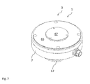
- the Fig. 7 and 8th show a third embodiment of a motion sensor system according to the invention 1.
- the motion sensor system 1, a first Rotary motion sensor 3 according to the second embodiment.
- the housing part 7 is closed at its end which is opposite to the axle-side end 17 of the first shaft 19 with a closure 65.
- This may be advantageous for operating the motion sensor system 1 exclusively with the first rotary motion sensor 3.
- the first rotary motion sensor 3 has a first coupling part 49, it can be subsequently connected to a second rotary motion sensor 5.
- the shutter 65 removed and instead a second rotary motion sensor 5 are set with its associated housing part 9 on the housing part 7, wherein the first shaft 19 of the first rotary motion sensor 3 is connected torsionally rigid with the shaft 55 of the second rotary motion sensor 5.
- the closure 65 may include an additional lid 67 which is removable from the closure 65.
- the cover 67 may be configured such that it conceals the first coupling part 49 of the first shaft 19 in an assembled state.
- the first coupling part 49 may be like the coupling part 49 with Fig. 5 be configured described embodiment.
- the second coupling part 57 of the second rotation sensor 5 (not shown) may be made as described with reference to FIGS Fig. 6 be formed embodiment described.
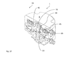
- the Fig. 9 and 10 show a fourth embodiment of a motion sensor system according to the invention 1.
- an opening 68 of the closure 65 can be closed by a cover 67 (not shown).
- a shaft 55 may be connected to the first shaft 19 without to have their own storage.
- the shaft 55 may have a second coupling part 57, which is rotatably configured with a first coupling part 49 of the first shaft 19 connected.
- the resulting common shaft 69 is then stored only in the first rotary motion sensor 3.
- the second shaft 55 carries at least one further measuring standard 39 of the second rotary motion sensor 5.
- the housing part 9 of the second rotational movement sensor 5, the query elements 45 which can cooperate with the other measuring graduations 39. If the associated housing part 9 of the second rotary motion sensor 5 is placed on the housing part 7 of the first rotary motion sensor 3, then the shaft 55 projects with the measuring graduations 39 into the housing part 9 so that the measuring graduations 39 can cooperate with the interrogation elements 45.
- a motion sensor system with two rotational motion sensors is formed and the housing parts 7 and 9 form a common system housing 11.
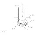
- Fig. 11 merely shows, by way of example, a rotary motion sensor in order to represent the position of the first shaft 19 according to the invention on a rotary motion sensor.
- the arrangement of the first shaft 19 and its axle-side end 17 described below can be used with all previously described embodiments of a motion sensor system according to the invention.
- the first shaft 19 has an axle-side end 17 and extends therefrom along the shaft axis W into the first rotary motion sensor 3.
- the first shaft 19 is connected in a rotationally fixed manner to at least one measuring graduation 27 of the first rotary motion sensor 3.
- the first shaft 19 can be pressed and / or pinned with at least one material measure 27.
- the shaft 19 has a shaft diameter 71.
- the shaft diameter 71 extends over the entire shaft 19 with the exception of its axle-side end 17.
- the shaft 19 has a shaft head 73 with a diameter 75 which is larger than the shaft diameter 71.
- the shaft head 73 can serve this purpose to hold an output member 21 to the shaft 19.
- At least the shaft head 73 can serve to hold an output element 21 in the direction of the axle-side end 17.
- the driven element 21 is pressed onto the first shaft 19.
- the output element 21 may have a receiving opening 77 for the shaft whose diameter 79 corresponds approximately to the shaft diameter 71.
- the shaft diameter 71 may increase towards the shaft head 73, so that the driven element 21 can first slide slightly over the shaft 19 and only then enters into a press connection with the shaft 19 in the region of the shaft head 73 , Due to the press connection between the first shaft 19 and the driven element 21, the driven element 21 can transmit a rotational movement to the first shaft 19 without play.
- the first shaft 19 may have an opening 81 for a positive locking element 83.
- the opening 81 preferably extends continuously through the shaft 19 and perpendicular to the shaft axis W. Also preferably, the opening 81 extends so that it intersects the shaft axis W, that passes centrally through the first shaft 19.
- the opening 81 may also extend at least in sections through the shaft head 73.
- a positive locking element 83 can be used, which can form a positive connection with the driven element 21.
- the output element 21 preferably has at least one bulge 85 which extends away from the receiving opening 77.
- the bulge 85 preferably extends radially from the shaft axis W into the abrasion element 21.
- the driven element 21 preferably has two bulges 85 lying opposite one another. By two opposing bulges 85, an elongated receptacle 87 may be formed for the positive-locking element 83. In Fig.
- a first shaft 19 according to the invention is shown in a sectional view, wherein the cutting plane is shown by an elongate positive-locking element 83 in the shaft 19 and by an elongated receptacle 87 in an output member 21 formed as a driving plate 25.
- the positive locking element 83 can first be inserted into the opening 81 in the first shaft 19 and then the driven element 21 can be pressed onto the first shaft 19 until the driven element 21 bears against the shaft head 73 ,
- the at least one bulge 85 may be arranged so that the form-locking element 83 is arranged in this, when the output element 21 rests against the shaft head 73.
- the output element 21 may be clamped in the mounted state between the shaft head 73 and an inner ring 89 of a bearing 91 of the first rotary motion sensor 3.
- the shaft 19 may be held with the output member 21 so that both elements are still rotatable together about the shaft axis W.
- the output element 21 is formed as a driver member 23.
- the driver member 23 has at least one slot-shaped receptacle 93 for a drive element of the axis of the rail vehicle. In order to keep the driver member 23 compact, it is preferably formed as a drive plate 25.
- the receptacle 93 for a drive element then preferably extends radially to the shaft axis W into the driver disk 25.
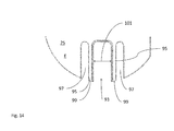
- Fig. 14 shows a second embodiment of a drive plate according to the invention 25.
- the receptacle 93 for a drive element of the axle of the rail vehicle is bounded by two elastically deflectable tongues 95.
- the drive plate 25 has two indentations 97 extending parallel to the slot-shaped receptacle 93 into the drive plate.
- the tongues 95 are then bounded by the receptacle 93 and the recesses 97. Free ends 99 of the tongues 95 are deflectable into the indentations 97.
- the tongues 95 are deflectable within a disc plane E of the drive plate 25.
- the receptacle 93 has a receiving diameter 101.
- the receiving diameter 101 is measured perpendicular to the rectilinear tongues 95.
- the receiving diameter 101 is preferably smaller than a diameter of a drive element of the axis of the rail vehicle. If a drive element is inserted into the receptacle 93, the tongues 95 are elastically deflected, since the drive element has a larger diameter than receptacle 93. In this way, a drive element can be held without play in the receptacle 93.
Landscapes
- Physics & Mathematics (AREA)
- General Physics & Mathematics (AREA)
- Engineering & Computer Science (AREA)
- General Engineering & Computer Science (AREA)
- Mechanical Engineering (AREA)
- Transmission And Conversion Of Sensor Element Output (AREA)
Priority Applications (1)
| Application Number | Priority Date | Filing Date | Title |
|---|---|---|---|
| EP15157369.8A EP3064793A1 (fr) | 2015-03-03 | 2015-03-03 | Système de capteur de mouvement pour véhicules sur rail |
Applications Claiming Priority (1)
| Application Number | Priority Date | Filing Date | Title |
|---|---|---|---|
| EP15157369.8A EP3064793A1 (fr) | 2015-03-03 | 2015-03-03 | Système de capteur de mouvement pour véhicules sur rail |
Publications (1)
| Publication Number | Publication Date |
|---|---|
| EP3064793A1 true EP3064793A1 (fr) | 2016-09-07 |
Family
ID=52648834
Family Applications (1)
| Application Number | Title | Priority Date | Filing Date |
|---|---|---|---|
| EP15157369.8A Withdrawn EP3064793A1 (fr) | 2015-03-03 | 2015-03-03 | Système de capteur de mouvement pour véhicules sur rail |
Country Status (1)
| Country | Link |
|---|---|
| EP (1) | EP3064793A1 (fr) |
Cited By (3)
| Publication number | Priority date | Publication date | Assignee | Title |
|---|---|---|---|---|
| EP3296184A1 (fr) * | 2016-09-16 | 2018-03-21 | Baumer Electric Ag | Dispositif et procédé destiné à surveiller l'arrêt de véhicules, en particulier des véhicules sur rails |
| DE102016219681A1 (de) * | 2016-10-11 | 2018-04-12 | Siemens Aktiengesellschaft | Verfahren und Vorrichtung zum Erkennen einer Positionsänderung eines zumindest teilweise abgeschalteten Fahrzeugs |
| AT526691A4 (de) * | 2022-12-30 | 2024-06-15 | Plasser & Theurer Export Von Bahnbaumaschinen Gmbh | Verfahren und System zur Bestimmung eines auf eine Radsatzwelle eines Schienenfahrzeugs wirkenden Stördrehmoments sowie Schienenfahrzeug |
Citations (3)
| Publication number | Priority date | Publication date | Assignee | Title |
|---|---|---|---|---|
| DE2744378A1 (de) * | 1977-10-01 | 1979-04-05 | Werner Komenda | Verfahren und vorrichtung zur messung von kreisbewegungsgroessen |
| US4171939A (en) * | 1978-03-27 | 1979-10-23 | Sundstrand Corporation | Arrangement for mounting a gear on a shaft |
| JPS59126209A (ja) * | 1983-01-07 | 1984-07-20 | Matsushita Electric Works Ltd | ロ−タリ−エンコ−ダ |
-
2015
- 2015-03-03 EP EP15157369.8A patent/EP3064793A1/fr not_active Withdrawn
Patent Citations (3)
| Publication number | Priority date | Publication date | Assignee | Title |
|---|---|---|---|---|
| DE2744378A1 (de) * | 1977-10-01 | 1979-04-05 | Werner Komenda | Verfahren und vorrichtung zur messung von kreisbewegungsgroessen |
| US4171939A (en) * | 1978-03-27 | 1979-10-23 | Sundstrand Corporation | Arrangement for mounting a gear on a shaft |
| JPS59126209A (ja) * | 1983-01-07 | 1984-07-20 | Matsushita Electric Works Ltd | ロ−タリ−エンコ−ダ |
Cited By (5)
| Publication number | Priority date | Publication date | Assignee | Title |
|---|---|---|---|---|
| EP3296184A1 (fr) * | 2016-09-16 | 2018-03-21 | Baumer Electric Ag | Dispositif et procédé destiné à surveiller l'arrêt de véhicules, en particulier des véhicules sur rails |
| DE102016219681A1 (de) * | 2016-10-11 | 2018-04-12 | Siemens Aktiengesellschaft | Verfahren und Vorrichtung zum Erkennen einer Positionsänderung eines zumindest teilweise abgeschalteten Fahrzeugs |
| AT526691A4 (de) * | 2022-12-30 | 2024-06-15 | Plasser & Theurer Export Von Bahnbaumaschinen Gmbh | Verfahren und System zur Bestimmung eines auf eine Radsatzwelle eines Schienenfahrzeugs wirkenden Stördrehmoments sowie Schienenfahrzeug |
| AT526691B1 (de) * | 2022-12-30 | 2024-06-15 | Plasser & Theurer Export Von Bahnbaumaschinen Gmbh | Verfahren und System zur Bestimmung eines auf eine Radsatzwelle eines Schienenfahrzeugs wirkenden Stördrehmoments sowie Schienenfahrzeug |
| WO2024141550A1 (fr) | 2022-12-30 | 2024-07-04 | Plasser & Theurer, Export von Bahnbaumaschinen, Gesellschaft m.b.H. | Procédé et système de détermination d'un couple de perturbation agissant sur un essieu de paire de roues d'un véhicule ferroviaire, et véhicule ferroviaire |
Similar Documents
| Publication | Publication Date | Title |
|---|---|---|
| DE4433825C2 (de) | Stelleinrichtung mit einer Kupplungslageregelung | |
| DE102008028618B3 (de) | Elektromechanische Gebereinrichtung | |
| DE3211748C2 (fr) | ||
| DE4134794A1 (de) | Weggeber fuer einen stellantrieb, insbesondere in einem fahrzeug | |
| DE112017005599B4 (de) | Lineare antriebsvorrichtung, motor, und lineare antriebsvorrichtung - herstellungsverfahren | |
| EP3265830A2 (fr) | Système de capteur pour un palier de roulement ainsi qu'ensemble formant palier de roulement comprenant un système de capteur de ce type | |
| WO2011161113A2 (fr) | Capteur d'angle | |
| DE3881743T2 (de) | Lenkkoppel-Fühlereinrichtung. | |
| DE19723430A1 (de) | Lenksensoreinheit | |
| DE202009006227U1 (de) | Elektrischer Stellantrieb | |
| EP4242616B1 (fr) | Dispositif de capteur de couple, ensemble de conducteur de flux et conducteur de flux | |
| DE102016124370A1 (de) | Sensorvorrichtung sowie Verfahren zum Zusammenbau einer Sensorvorrichtung | |
| EP3064793A1 (fr) | Système de capteur de mouvement pour véhicules sur rail | |
| DE102014102982B3 (de) | Lenkwinkelsensor | |
| EP4163597A1 (fr) | Système de direction pour véhicule automobile | |
| EP1903418B1 (fr) | Dispositif destiné à la transformation de mouvements mécaniques en signaux électriques | |
| DE19706209A1 (de) | Vorrichtung zur Steuerung, insbesondere Endabschaltung einer motorischen Antriebsvorrichtung einer Wickelwelle eines Rolladens, Garagentors o. dgl. | |
| EP3320305B1 (fr) | Dispositif de détection avec construction modulaire | |
| EP0439037A1 (fr) | Armature | |
| EP0518100B1 (fr) | Servo-entraînement | |
| EP1312534B1 (fr) | Dispositif pour la détermination de l'angle de braquage d'un volant | |
| DE202009009929U1 (de) | Sensoranordnung für ein Rollstuhlrad | |
| DE3438718C2 (de) | Präzisionskupplung für die winkelgetreue Übertragung rotatorischer Bewegungen | |
| DE102014118041B4 (de) | Drehgeber und Verfahren zu dessen Montage an einer Baugruppe | |
| DE10065240C2 (de) | Lenkwinkelmesseinrichtung |
Legal Events
| Date | Code | Title | Description |
|---|---|---|---|
| PUAI | Public reference made under article 153(3) epc to a published international application that has entered the european phase |
Free format text: ORIGINAL CODE: 0009012 |
|
| AK | Designated contracting states |
Kind code of ref document: A1 Designated state(s): AL AT BE BG CH CY CZ DE DK EE ES FI FR GB GR HR HU IE IS IT LI LT LU LV MC MK MT NL NO PL PT RO RS SE SI SK SM TR |
|
| AX | Request for extension of the european patent |
Extension state: BA ME |
|
| STAA | Information on the status of an ep patent application or granted ep patent |
Free format text: STATUS: THE APPLICATION IS DEEMED TO BE WITHDRAWN |
|
| 18D | Application deemed to be withdrawn |
Effective date: 20170308 |