EP3064879B1 - Dispositif de radiateur a ecoulement croise - Google Patents
Dispositif de radiateur a ecoulement croise Download PDFInfo
- Publication number
- EP3064879B1 EP3064879B1 EP16157820.8A EP16157820A EP3064879B1 EP 3064879 B1 EP3064879 B1 EP 3064879B1 EP 16157820 A EP16157820 A EP 16157820A EP 3064879 B1 EP3064879 B1 EP 3064879B1
- Authority
- EP
- European Patent Office
- Prior art keywords
- flow channels
- flow
- half shell
- water pocket
- heating
- Prior art date
- Legal status (The legal status is an assumption and is not a legal conclusion. Google has not performed a legal analysis and makes no representation as to the accuracy of the status listed.)
- Not-in-force
Links
- 238000010438 heat treatment Methods 0.000 claims description 129
- XLYOFNOQVPJJNP-UHFFFAOYSA-N water Substances O XLYOFNOQVPJJNP-UHFFFAOYSA-N 0.000 claims description 55
- 238000004519 manufacturing process Methods 0.000 claims description 7
- 230000001419 dependent effect Effects 0.000 claims description 2
- 238000000034 method Methods 0.000 claims 1
- 230000000694 effects Effects 0.000 description 4
- 230000008901 benefit Effects 0.000 description 3
- 238000009826 distribution Methods 0.000 description 3
- 239000012530 fluid Substances 0.000 description 3
- 238000003466 welding Methods 0.000 description 3
- 238000009434 installation Methods 0.000 description 2
- 230000004888 barrier function Effects 0.000 description 1
- 239000004020 conductor Substances 0.000 description 1
- 238000005304 joining Methods 0.000 description 1
- 239000002184 metal Substances 0.000 description 1
- 238000003825 pressing Methods 0.000 description 1
- 238000004080 punching Methods 0.000 description 1
- 230000001172 regenerating effect Effects 0.000 description 1
- 230000007704 transition Effects 0.000 description 1
Images

Classifications
-
- F—MECHANICAL ENGINEERING; LIGHTING; HEATING; WEAPONS; BLASTING
- F28—HEAT EXCHANGE IN GENERAL
- F28D—HEAT-EXCHANGE APPARATUS, NOT PROVIDED FOR IN ANOTHER SUBCLASS, IN WHICH THE HEAT-EXCHANGE MEDIA DO NOT COME INTO DIRECT CONTACT
- F28D1/00—Heat-exchange apparatus having stationary conduit assemblies for one heat-exchange medium only, the media being in contact with different sides of the conduit wall, in which the other heat-exchange medium is a large body of fluid, e.g. domestic or motor car radiators
- F28D1/02—Heat-exchange apparatus having stationary conduit assemblies for one heat-exchange medium only, the media being in contact with different sides of the conduit wall, in which the other heat-exchange medium is a large body of fluid, e.g. domestic or motor car radiators with heat-exchange conduits immersed in the body of fluid
- F28D1/03—Heat-exchange apparatus having stationary conduit assemblies for one heat-exchange medium only, the media being in contact with different sides of the conduit wall, in which the other heat-exchange medium is a large body of fluid, e.g. domestic or motor car radiators with heat-exchange conduits immersed in the body of fluid with plate-like or laminated conduits
- F28D1/0308—Heat-exchange apparatus having stationary conduit assemblies for one heat-exchange medium only, the media being in contact with different sides of the conduit wall, in which the other heat-exchange medium is a large body of fluid, e.g. domestic or motor car radiators with heat-exchange conduits immersed in the body of fluid with plate-like or laminated conduits the conduits being formed by paired plates touching each other
- F28D1/0316—Assemblies of conduits in parallel
-
- F—MECHANICAL ENGINEERING; LIGHTING; HEATING; WEAPONS; BLASTING
- F28—HEAT EXCHANGE IN GENERAL
- F28D—HEAT-EXCHANGE APPARATUS, NOT PROVIDED FOR IN ANOTHER SUBCLASS, IN WHICH THE HEAT-EXCHANGE MEDIA DO NOT COME INTO DIRECT CONTACT
- F28D21/00—Heat-exchange apparatus not covered by any of the groups F28D1/00 - F28D20/00
- F28D2021/0019—Other heat exchangers for particular applications; Heat exchange systems not otherwise provided for
- F28D2021/0035—Other heat exchangers for particular applications; Heat exchange systems not otherwise provided for for domestic or space heating, e.g. heating radiators
-
- Y—GENERAL TAGGING OF NEW TECHNOLOGICAL DEVELOPMENTS; GENERAL TAGGING OF CROSS-SECTIONAL TECHNOLOGIES SPANNING OVER SEVERAL SECTIONS OF THE IPC; TECHNICAL SUBJECTS COVERED BY FORMER USPC CROSS-REFERENCE ART COLLECTIONS [XRACs] AND DIGESTS
- Y02—TECHNOLOGIES OR APPLICATIONS FOR MITIGATION OR ADAPTATION AGAINST CLIMATE CHANGE
- Y02B—CLIMATE CHANGE MITIGATION TECHNOLOGIES RELATED TO BUILDINGS, e.g. HOUSING, HOUSE APPLIANCES OR RELATED END-USER APPLICATIONS
- Y02B30/00—Energy efficient heating, ventilation or air conditioning [HVAC]
Definitions
- the invention relates to a radiator device with at least one heating element which is formed from two heating element half-shells placed against one another.
- Each half-shell has a plurality of elongated depressions which are arranged parallel to one another and form grooves.
- the two half-shells are conventionally placed on top of one another in such a way that each groove-like depression of one half-shell borders on a corresponding groove-like depression of the other half-shell.
- the two adjacent groove-like depressions of the two half-shells then form an elongated fluid flow channel for the heating medium in the assembled state of the half-shells.
- each heating element therefore has a plurality of elongated flow channels arranged parallel to one another and next to one another, through which the heating medium flows through the heating medium.
- the flow channels are connected to a heating flow from which the flow channels are fed with warm heating medium.
- the flow channels are connected to a heating return, to which the cooled heating medium is fed again from the flow channels.
- a water pocket is formed in the heating element between the flow connection and one end of the flow channels, from which all flow channels branch off.
- the water pocket can be formed by groove-like, elongated depressions in the two half-shells. Each half-shell has exactly one groove-like depression for the water pocket.
- the groove-like depressions for the flow channels branch off from the groove-like depressions of the water pocket.
- a corresponding water pocket can be formed in the heating element, into which all flow channels open.
- Such radiators are placed near a room wall of a house and connected to a heating flow and a heating return.
- Heating medium typically water
- the flow connection of the heating elements is provided in their upper area so that the heating medium flows through the heating elements from top to bottom.
- each heating element has a return connection in order to supply the heating medium to the heating return after flowing through the heating element.
- a room-side and a wall-side heating element are usually arranged parallel to each other and each connected with the same flow and return. The heating medium flows through the two heating elements in parallel.
- the heating medium supplied to the return line has cooled down by approximately 10 K to approximately 40 ° C. after flowing through the radiator.
- EP 0 176 997 A2 describes a radiator with two half-shells placed against one another, of which the first half-shell only has vertical flow channels, while the second half-shell has intersecting vertical and horizontal flow channels. This is intended to improve the heat transfer to a convection baffle connected on the outside to the second half-shell.
- the radiator described in this document cannot be produced. Rather, the production is technically complex and expensive.
- EP 0 397 487 A2 describes a heat exchanger with intersecting fluid channels.
- the document shows a radiator device with the features of the preamble of claim 1.
- the object of the invention is to provide a radiator device that is easy to manufacture and has an improved energy transfer at low flow temperatures.
- the two heating element half-shells are placed against one another in the same orientation and are firmly connected to one another, so that the depressions of one half-shell for the flow channels are aligned in the same way as the depressions of the other half-shell for the flow channels, the According to the invention, the two half-shells are rotated by 90 degrees with respect to one another, that is to say placed against one another transversely and firmly connected to one another.
- the groove-like depressions of the one half-shell for the flow channels run transverse to the groove-like depressions of the other half-shell for the flow channels.
- flow channels for the heating medium are formed, which cross one another and pass through the heating element in the manner of a grid. It is crucial that the flow channels of one half-shell do not cross each other, which applies to both half-shells.
- the lattice structure of the flow channels for the cross-flow is only made possible by joining the two half-shells to form a heating element.
- a direct transfer between adjacent flow channels of one half-shell is prevented and is only made possible indirectly via the transverse flow channels of the other half-shell.
- a direct transfer of heating medium means a transfer in which the heating medium does not leave the flow area for the heating medium formed by the relevant half-shell.
- Such a direct transfer between adjacent flow channels of a half-shell is prevented by the fact that between the flow channels elongated, raised areas arranged parallel to one another are formed, which correspond in length to the flow channels and form a barrier for the heating medium over the entire length of the flow channels.
- This type of half-shell corresponds to the half-shell currently manufactured as standard.
- the cross-flow is only made possible by the fact that half-shells manufactured by standard are 90 degrees twisted against each other. This enables the production of a radiator with cross flow in a technically simple and inexpensive manner.
- the flow channels formed by one half shell are typically oriented exclusively vertically and the flow channels of the other half shell are oriented exclusively horizontally.
- the heating medium flows through the vertically arranged flow channels in a conventional manner from top to bottom.
- the horizontal flow channels of the other half-shell are flowed horizontally from one side to the other, that is to say from right to left or from left to right.
- the heating medium of a vertical flow channel mixes with the heating medium of a horizontal flow channel.
- radiator device offers in particular the decisive advantage of heating a room with lower flow temperatures than in conventional radiators.
- the two heating element half-shells which are placed against one another and rotated by 90 degrees with respect to one another, are each provided with at least one groove-like depression for at least one water pocket, from which the flow channels arranged transversely to this depression branch off.
- a heating element with a water pocket running along a first, for example upper, edge, from which flow channels branch off, and with one along one to the first edge Adjacent second, for example lateral (right or left) edge running second water pocket, from which the other flow channels branch off.
- the water pockets are not flow channels.
- the water pockets primarily serve to supply heating medium to the flow channels or to take up heating medium from the flow channels.
- the flow channels primarily serve to flow heating medium through the heating element in order to achieve heat transfer from the heating medium to the heating element and the adjacent room air. While the flow channels run through the heating element from one side to the opposite side, the water pockets are arranged in the edge region of the heating element and connected to the outer ends of the flow channels. While the flow channels of adjacent half-shells cross each other, a crossing of the water pockets of adjacent heating elements is not provided.
- the two water pockets are preferably provided with a common flow connection in order to be fed from the same heating flow.
- the heating medium from the heating flow reaches both water pockets and spreads in them.
- the heating medium then flows through the respective flow channels of the relevant half-shell from the water pockets. This enables a particularly uniform, approximately homogeneous heat distribution of the heating element.
- Each half-shell is preferably provided with a first water pocket for the heating flow in the form of a groove-like depression and with a second water pocket for the heating return in the form of a groove-like depression.
- the two water pockets are then connected on opposite sides of the flow channels to the ends of the flow channels, so that the one water pocket removes the heating medium from the flow channels Supply heating flow and the other water pocket takes the heating medium from the flow channels and feeds the heating return.
- the thermostatic valve is not arranged and connected to the upper end of the heating element as in the conventional radiators, but is arranged at a height below the upper edge. This avoids a build-up of heat that closes the thermostatic valve and blocks the heating supply. Such heat build-up can occur in the upper area of a radiator installed in a wall niche. If the thermostatic valve is located in the upper area of the radiator, it closes early due to the heat build-up and stops further heat transfer.
- the temperature difference between the room temperature set on the thermostatic valve and the heat build-up in a wall niche can be up to 10 degrees. Users usually avoid this problem by setting an excessive target room temperature on the thermostat, for example, 26-28 degrees Celsius, in order to obtain a desired living room temperature in the range of 20-22 degrees. As a result, this leads to an increased energy expenditure.
- thermostatic valve is located further down, for example at about 40-60 percent of the height difference between the upper and lower edge of the radiator or between the upper water pocket connected to the flow and the lower water pocket connected to the return, one can such heat build-up can be avoided.
- the thermostatic valve can, for example, be in fluid connection with a lateral, vertical water pocket and indirectly via this with the upper, horizontal water pocket.
- the flow connection can be connected to conventional, existing connection dimensions and, for example, with a hidden flow supply inside the radiator on the side heating wall down to the level of the thermostatic valve and there with the valve assembly be connected to the heating walls.
- the thermostat then does not sit in the upper area of a wall niche, as is conventional, but rather at a medium height, where the thermostat can react and act better and more precisely to the room heat.
- the radiator according to the invention has the particular advantage that even with low flow temperatures, which are generated with the aid of regenerative energies or heat pumps, there is a uniform heat transfer which is sufficient for heating a room.
- Conventional radiators require flow temperatures of more than 40 ° C and, if possible, more than 50 ° C.
- the radiator according to the invention is able to heat a room with flow temperatures of more than 50 ° C. and less than 30 ° C.
- the radiator according to the invention can in particular be used as a flat radiator for heating a living space, the flat radiator being able to be made available as a ready-made radiator, which is made available as a pre-produced unit before installation.
- flat radiators are provided as a valve radiator with a connection from below and a pre-assembled valve set (thermostatic valve) as well as a concealed flow supply or as a compact radiator for the side connection.
- the heating surfaces are usually offered with system temperatures of 70 ° C / 55 ° C (flow temperature / return temperature) or 55 ° C / 45 ° C.
- the conventional flat radiators are not suitable for the use of lower flow temperatures, similar to underfloor heating, because the sufficient heat cannot be released into the room via the heating wall and its surface. This is due in particular to the fact that the temperature drop in the radiator is high due to the vertical flow of water between the upper and lower edges of the radiator. A lower temperature drop would be required for operation with lower flow temperatures.
- the lattice structure of the flow channels according to the invention can also be referred to as a honeycomb structure.
- the two radiator half-shells can be connected to one another in a conventional manner by spot welding.
- the welding points are placed between the mutually contacting sections of the two half-shells, while the groove-like depressions are spaced apart, so that in the area of the depressions the heating medium can flow through the heating element in the flow channels formed between the half-shells.
- the two half-shells can be produced with the same manufacturing process, for example by identical pressing and / or punching, and are not subsequently, as is conventional, with the same orientation Flow channels of the two half-shells placed next to each other, but rather with an orientation rotated by 90 degrees with respect to one another. This can be achieved by rotating one half shell by 90 degrees with respect to the other half shell. This type of manufacture is particularly advantageous for half-shells which are square in plan view.
- the reduced temperature difference according to the invention in the vertical direction of the radiator of approximately 2-3 degrees Celsius, this can be operated with system temperatures of 35 degrees Celsius / 32 degrees Celsius (flow temperature / return temperature) and can be used in particular in combination operation with underfloor heating.
- the calorific value benefit of a heater operating the radiator according to the invention is improved and the energy requirement of the heating system is reduced. Energy costs can be reduced by up to 40 percent.
- a feed horizontally oriented water pocket becomes a vertically oriented water pocket on the side edge of the radiator and allows the supply and return lines to be positioned individually and variably.
- the heating element is preferably arranged in a room in such a way that the half-shell with the horizontally guided flow channels points towards the room side, while the half-shell with the vertically guided flow channels points towards the wall side. This creates a visually more pleasing effect compared to the conventional heating surfaces with vertical guidance of the flow channels.
- the radiator has two heating elements, each of which is formed from two half-shells.
- the half-shells of different heating elements lying opposite one another on the inside have the vertical flow channels, the vertically guided ones Flow channels of the inner half-shells are thermally connected to one another by vertically guided convection baffles. This creates a vertical airflow by convection.
- the two outer half-shells which each form the outer sides of the radiator (room side and wall side), have the horizontally running flow channels. This results in an optically particularly pleasing effect of the radiator on the outside.
- the heat transfer area is increased by approximately 15% to 20%, depending on the size of the radiator, compared to a conventional radiator with the same amount of heating medium, thereby increasing the performance of the radiator.
- the invention enables the use of a radiator with such low flow temperatures that operation with heat pumps and, for example, in combination with underfloor heating is made possible and in the transition period with mild outside temperatures (approx. 5 degrees Celsius - 15 degrees Celsius) energy savings of up to 40% enables.
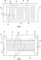
- the radiator device 10 has two flat heating elements 12, 14 arranged parallel to one another. Both heating elements 12, 14 are each in arranged in a vertical plane.
- the first heating element 12 forms the front of the radiator 10 and the second heating element 14 forms the rear of the radiator 10.
- the front faces the room to be heated, while the rear of the radiator 10 faces a room wall.
- the two heating elements 12, 14 are connected to a flow connection 16 and to a return connection 18.
- the flow connection 16 is connected to the heating flow during operation of the radiator device 10.
- the return connection 18 is connected to the heating return during operation of the radiator device 10.
- Each of the two heating elements 12, 14 is formed from a first half-shell 20 and a second half-shell 22.
- Each of the two half-shells 20, 22 is pressed from a metal sheet, elongated, groove-forming depressions being produced in each case.
- First and second elongated depressions 28, 30 are formed in each of the two half-shells along opposing edges 24, 26.
- the two recesses 28, 30 are each connected to one another by a plurality of elongated and parallel third recesses 32.
- the third depressions 32 of each half-shell 20, 22 are arranged transversely to the first and second depressions 28, 30 of the relevant half-shell.
- the first depressions 28 of each half-shell form a flow water pocket and are connected to a common flow connection 16, via which the flow water pockets 29 are supplied with heating medium from the heating flow.
- the heating medium flows from the feed water pocket 29 into flow channels 33 formed by the third recesses 32 and is fed to the return water pocket 31 formed by the second recess 30.
- the two return water pockets 31 of the two half-shells 20, 22 are connected to a common return connection 18, via which the heating medium from the return water pockets 31 is fed to the heating return.
- the half-shells 20, 22 are arranged rotated by 90 degrees to one another such that the depressions 28, 30, 32 of the first half-shell 20 are arranged transversely to the corresponding depressions 28, 30, 32 of the second half-shell 22.
- the flow channels 33 of the first half-shell 20 formed by the third depressions 32 are oriented vertically, while the corresponding flow channels 33 of the second half-shell 22 are oriented horizontally.
- the flow channels 33 of the two half-shells 20, 22 are thus arranged in the interconnected state of the half-shells 20, 22 crossing one another in the manner of a grid.
- the heating medium flowing through the flow channels 33 of the first half-shell 20 mixes with the heating medium flowing through the flow channels 33 of the second half-shell 22.
- the flow channels 33 of the first half-shell 20 are flowed through vertically from top to bottom, while the flow channels 33 of the second half-shell 22 are flowed through from left to right or from right to left in the horizontal direction depending on the viewing direction.
- intersection points 36 are arranged distributed over a large part of the surface of the heating elements 12, 14, which results in a uniform heat distribution when heating medium flows through them.
- the two half-shells 20, 22 touch each other along the outer edges and in the contact surfaces 38 adjacent to the crossing points 36 and are firmly connected to one another in these regions, for example by welding.
- the thermostatic valve 40 for the temperature-dependent opening or closing of the supply of heating medium from the heating flow and the flow connection 16 are not arranged at the level of the upper water pocket 28 in the area of the upper edge 24, 27 of the heating elements 12, 14, but rather at a level below the upper water pocket 28.
- the thermostatic valve 40 and the flow connection 16 are arranged approximately halfway between the water pocket 28 and the return connection 18 and are connected to a lateral water pocket 30. This avoids that in the event of installation of the Radiator device 10 in a wall recess falsifies the switching activity of the thermostatic valve.
- the thermostatic valve 40 is a valve set integrated in the radiator 10.
- the two inner, facing half-shells 20, 22 of the radiator device 10 have the vertical flow channels 33, while the two outer half-shells 22, 20 assigned to the room or the room wall have the horizontal flow channels 33 .
- the vertical flow channels 33 of the inner half-shells 20, 22 are thermally connected to one another by convection baffles made of thermally conductive material in order to achieve a convection air flow inside the radiator device 10.
- FIG. 1 there is a side connection to the flow and return connections provided on the wall.
- the flow connection 16 of the radiator 10 and the valve set of the thermostatic valve 40 are not connected to the heating elements 12, 14 at half height, but rather in the manner of a conventional compact radiator at the flow connection on the wall side.
- the radiator device 10 according to the invention can also be connected in the manner of a conventional valve radiator with bottom-side connections for flow and return. From the radiator-side return connection 18, the connection to the return is then made vertically downwards and not how in Figure 1 shown, horizontally to the side.
- the connection between the flow connection 16 on the radiator side is made with the flow on the bottom side via a connecting pipe which runs vertically downward between the heating elements 12, 14.
- This variant is not shown in the figures, but is made possible in the same way according to the invention.
Landscapes
- Engineering & Computer Science (AREA)
- Physics & Mathematics (AREA)
- Thermal Sciences (AREA)
- Mechanical Engineering (AREA)
- General Engineering & Computer Science (AREA)
- Domestic Hot-Water Supply Systems And Details Of Heating Systems (AREA)
Claims (8)
- Dispositif de chauffage (10) comprenant au moins un élément chauffant (12, 14) qui comporte deux demi-coques d'élément chauffant (20, 22) placées l'une contre l'autre, chaque demi-coque comportant une pluralité de creux allongés (32) qui sont disposés parallèlement les uns aux autres et qui forment des rainures,
les creux (32) de type rainures d'une demi-coque (20) étant disposés transversalement aux creux (32) de type rainures de l'autre demi-coque (22) de telle sorte que les creux (32) de type rainures des deux demi-coques (20, 22) forment des conduits d'écoulement (33) qui se croisent et sont ménagés dans l'élément chauffant à la manière d'une grille et qui sont destinés au milieu chauffant, et
chaque demi-coque (20, 22) comporte au moins un creux (28, 30) de type rainure qui forme une poche d'eau (29, 31) destiné au milieu chauffant, caractérisée en ce que le creux (28, 30) est ménagé transversalement aux conduits d'écoulement (33) de la demi-coque, chacune des poches d'eau (29, 31) étant reliée à un raccord (16, 18), destiné à la colonne de chauffage montante ou à la colonne de chauffage de retour, et aux conduits d'écoulement (33) de la demi-coque. - Dispositif de chauffage selon la revendication 1, caractérisé en ce que les conduits d'écoulement (33) d'une demi-coque (20) sont orientés verticalement et les conduits d'écoulement (33) de l'autre demi-coque (22) sont orientés horizontalement.
- Dispositif de chauffage selon l'une des revendications précédentes, caractérisé en ce que les rainures sont formées de manière à ce que le milieu chauffant circulant à travers les conduits d'écoulement (33) de l'une des demi-coques (20) se mélange avec le milieu chauffant s'écoulant à travers les conduits d'écoulement (33) de l'autre demi-coque (22) aux points d'intersection (36) des conduits d'écoulement (33).
- Dispositif de chauffage selon l'une des revendications 1 à 3, caractérisé en ce que chaque demi-coque comporte, sur des côtés opposés, un creux (28, 30) de type rainure formant une poche d'eau (29, 31) de sorte qu'une poche d'eau (29) est formée pour la colonne de chauffage montante et l'autre poche d'eau (31) est formée pour la colonne de chauffage de retour.
- Dispositif de chauffage selon l'une des revendications 1 à 4, caractérisé en ce qu'une poche d'eau (29, 31) d'une demi-coque (20) et une poche d'eau (29, 31) de l'autre demi-coque (22) comportent un raccord commun pour la colonne de chauffage montant ou la colonne de chauffage de retour.
- Dispositif de chauffage selon l'une des revendications précédentes, caractérisé en ce qu'une soupape thermostatique (40) est disposée à une hauteur située sous le bord supérieur (24, 27) du dispositif de chauffage et sous le raccord de colonne montante (16) du dispositif de chauffage pour ouvrir ou fermer l'alimentation de la colonne de chauffage montante en milieu chauffant en fonction de la température.
- Dispositif de chauffage selon la revendication précédente, caractérisé en ce que le dispositif de chauffage comporte une poche d'eau supérieure (29) reliée à la colonne de chauffage montante et une poche d'eau inférieure (31) reliée à la colonne de chauffage de retour, la soupape thermostatique (40) étant disposée à une hauteur d'environ 40 % à 60 % de la différence de hauteur entre les poches d'eau supérieure et inférieure.
- Procédé de fabrication d'un dispositif de chauffage (10) selon l'une des revendications précédentes comprenant au moins un élément chauffant (12, 14) qui est formé de deux demi-coques d'éléments chauffants (20, 22) placées l'une contre l'autre, chaque demi-coque (20, 22) comportant une pluralité de creux allongés (32) qui sont disposés parallèlement les uns aux autres et qui forment des rainures,
caractérisé en ce que
les deux demi-coques (20, 22) sont placées l'une contre l'autre de manière à être entraînées en rotation l'une par rapport à l'autre et sont reliées l'une à l'autre de manière fixe de telle sorte que les creux (32) de type rainures de la demi-coque forment des conduits d'écoulement (33), destinés au milieu chauffant, lesquels s'étendent transversalement aux conduits d'écoulement (33) qui sont formés par les creux (32) de type rainures de l'autre demi-coque (22) de sorte que, lorsque les demi-coques (20, 22) sont montées, l'élément chauffant (12, 14) comporte des conduits d'écoulement (33) qui se croisent à la manière d'une grille et qui sont traversés par l'élément chauffant et en ce que chaque demi-coque (20, 22) comporte au moins un creux (28, 30) de type rainure qui forme une poche d'eau (29, 31) destinée au milieu chauffant et qui est disposée transversalement aux conduits d'écoulement (33) de la demi-coque, la poche d'eau (29, 31) étant reliée à un raccord (16, 18), destiné à la colonne de chauffage montante ou à la colonne de chauffage de retour, et aux conduits d'écoulement (33) de la demi-coque.
Applications Claiming Priority (2)
| Application Number | Priority Date | Filing Date | Title |
|---|---|---|---|
| DE102015002555 | 2015-03-02 | ||
| DE102015208479.5A DE102015208479A1 (de) | 2015-03-02 | 2015-05-07 | Heizkörpervorrichtung mit Kreuzdurchströmung |
Publications (2)
| Publication Number | Publication Date |
|---|---|
| EP3064879A1 EP3064879A1 (fr) | 2016-09-07 |
| EP3064879B1 true EP3064879B1 (fr) | 2020-07-08 |
Family
ID=55527264
Family Applications (1)
| Application Number | Title | Priority Date | Filing Date |
|---|---|---|---|
| EP16157820.8A Not-in-force EP3064879B1 (fr) | 2015-03-02 | 2016-02-29 | Dispositif de radiateur a ecoulement croise |
Country Status (1)
| Country | Link |
|---|---|
| EP (1) | EP3064879B1 (fr) |
Family Cites Families (8)
| Publication number | Priority date | Publication date | Assignee | Title |
|---|---|---|---|---|
| DE1089534B (de) * | 1957-04-27 | 1960-09-22 | Buderus Eisenwerk | Plattenheizkoerper fuer Sammelheizungs-anlagen |
| GB1085161A (en) * | 1964-07-29 | 1967-09-27 | Henry Wilson & Company Ltd | Improvements in or relating to radiators for central heating systems |
| DE1778598A1 (de) * | 1967-05-19 | 1971-08-05 | Aga Platfoeraedling Ab | Heizkoerper mit offenen Zusatzkanaelen |
| NL161248C (nl) * | 1972-11-13 | 1980-01-15 | Schaefer Werke Kg | Samenstel voor het aansluiten van een verwarmings- lichaam, gevormd uit een aantal platte verwarmings- elementen, op een enkelvoudige buisinstallatie. |
| DE8429260U1 (de) | 1984-10-05 | 1985-01-03 | Prof. Dr. E. Sommer GmbH, 4750 Unna | Flachheizkoerper |
| GB8910966D0 (en) * | 1989-05-12 | 1989-06-28 | Du Pont Canada | Panel heat exchangers formed from thermoplastic polymers |
| DE19619888C2 (de) * | 1996-05-17 | 2001-07-19 | Kermi Gmbh | Heizvorrichtung sowie Thermostatventil und Thermostatkopf hierfür |
| DE202014105570U1 (de) * | 2013-11-19 | 2015-02-12 | Hermann Schmidt GmbH & Co. KG | Heizkörper mit flexibel positionierbarem Stellventil |
-
2016
- 2016-02-29 EP EP16157820.8A patent/EP3064879B1/fr not_active Not-in-force
Non-Patent Citations (1)
| Title |
|---|
| None * |
Also Published As
| Publication number | Publication date |
|---|---|
| EP3064879A1 (fr) | 2016-09-07 |
Similar Documents
| Publication | Publication Date | Title |
|---|---|---|
| DE112013004284T5 (de) | Wärmetauscher für Mikrokanal | |
| DE112013001706T5 (de) | Fahrzeuginterner Wärmetauscher und die Sammler verbindendes Element eines fahrzeuginternen Wärmetauschers | |
| DE202007005330U1 (de) | Heizkörper, insbesondere Röhrenheizkörper | |
| DE102016119781A1 (de) | Mehrwegeventil | |
| EP3064879B1 (fr) | Dispositif de radiateur a ecoulement croise | |
| DE19638714A1 (de) | Mattenartiger Wärmetauscher für Kühl- und/oder Heizzwecke | |
| EP2035757A1 (fr) | Élément chauffant, en particulier radiateur à tubes | |
| DE2440184A1 (de) | Ausgestaltung eines gliedes aus stahlblech fuer einen heizungsradiator | |
| DE4038495C2 (fr) | ||
| DE102015208479A1 (de) | Heizkörpervorrichtung mit Kreuzdurchströmung | |
| DE19832051C2 (de) | Heiz- bzw. Kühlkörper-Verteileranordnung | |
| EP3109561B1 (fr) | Radiateur | |
| DE2239086C2 (de) | Wärmetauscher, insbesondere für Durchlauferhitzer | |
| EP3067629B1 (fr) | Appareil de chauffage avec système de tuyauterie | |
| EP1229295A2 (fr) | Bloc d'échangeur de chaleur avec plusieurs chambres collectrices munies de fentes | |
| EP3077755A1 (fr) | Batteries de tubes pour un radiateur de chauffage et radiateur de chauffage muni de batteries de tubes de ce type | |
| EP2824399B1 (fr) | Élément de raccordement, radiateur et procédé de raccordement d'un radiateur | |
| DE3229757C2 (de) | Profilrohr für Wärmetauscher, insbesondere für Raumheizkörper | |
| DE102009025920A1 (de) | Flächenmodul zur Durchleitung eines Fluids und entsprechendes Heiz- und / oder Kühlsystem | |
| DE435115C (de) | Kuehler mit Gliedern aus hohlen Lamellen | |
| DE10004903B4 (de) | Plattenheizkörper | |
| DE29705694U1 (de) | Konvektor, Konvektorrohling und Konvektorbausatz | |
| EP1070921A2 (fr) | Radiateur avec raccord centré | |
| WO2009015629A2 (fr) | Radiateur tubulaire | |
| AT501943A1 (de) | Heizkörper |
Legal Events
| Date | Code | Title | Description |
|---|---|---|---|
| PUAI | Public reference made under article 153(3) epc to a published international application that has entered the european phase |
Free format text: ORIGINAL CODE: 0009012 |
|
| AK | Designated contracting states |
Kind code of ref document: A1 Designated state(s): AL AT BE BG CH CY CZ DE DK EE ES FI FR GB GR HR HU IE IS IT LI LT LU LV MC MK MT NL NO PL PT RO RS SE SI SK SM TR |
|
| AX | Request for extension of the european patent |
Extension state: BA ME |
|
| STAA | Information on the status of an ep patent application or granted ep patent |
Free format text: STATUS: REQUEST FOR EXAMINATION WAS MADE |
|
| 17P | Request for examination filed |
Effective date: 20170303 |
|
| RBV | Designated contracting states (corrected) |
Designated state(s): AL AT BE BG CH CY CZ DE DK EE ES FI FR GB GR HR HU IE IS IT LI LT LU LV MC MK MT NL NO PL PT RO RS SE SI SK SM TR |
|
| GRAP | Despatch of communication of intention to grant a patent |
Free format text: ORIGINAL CODE: EPIDOSNIGR1 |
|
| STAA | Information on the status of an ep patent application or granted ep patent |
Free format text: STATUS: GRANT OF PATENT IS INTENDED |
|
| INTG | Intention to grant announced |
Effective date: 20200128 |
|
| GRAS | Grant fee paid |
Free format text: ORIGINAL CODE: EPIDOSNIGR3 |
|
| GRAA | (expected) grant |
Free format text: ORIGINAL CODE: 0009210 |
|
| STAA | Information on the status of an ep patent application or granted ep patent |
Free format text: STATUS: THE PATENT HAS BEEN GRANTED |
|
| AK | Designated contracting states |
Kind code of ref document: B1 Designated state(s): AL AT BE BG CH CY CZ DE DK EE ES FI FR GB GR HR HU IE IS IT LI LT LU LV MC MK MT NL NO PL PT RO RS SE SI SK SM TR |
|
| REG | Reference to a national code |
Ref country code: AT Ref legal event code: REF Ref document number: 1288909 Country of ref document: AT Kind code of ref document: T Effective date: 20200715 Ref country code: CH Ref legal event code: EP |
|
| REG | Reference to a national code |
Ref country code: DE Ref legal event code: R096 Ref document number: 502016010411 Country of ref document: DE |
|
| REG | Reference to a national code |
Ref country code: IE Ref legal event code: FG4D Free format text: LANGUAGE OF EP DOCUMENT: GERMAN |
|
| REG | Reference to a national code |
Ref country code: LT Ref legal event code: MG4D |
|
| REG | Reference to a national code |
Ref country code: NL Ref legal event code: MP Effective date: 20200708 |
|
| PG25 | Lapsed in a contracting state [announced via postgrant information from national office to epo] |
Ref country code: NO Free format text: LAPSE BECAUSE OF FAILURE TO SUBMIT A TRANSLATION OF THE DESCRIPTION OR TO PAY THE FEE WITHIN THE PRESCRIBED TIME-LIMIT Effective date: 20201008 Ref country code: FI Free format text: LAPSE BECAUSE OF FAILURE TO SUBMIT A TRANSLATION OF THE DESCRIPTION OR TO PAY THE FEE WITHIN THE PRESCRIBED TIME-LIMIT Effective date: 20200708 Ref country code: HR Free format text: LAPSE BECAUSE OF FAILURE TO SUBMIT A TRANSLATION OF THE DESCRIPTION OR TO PAY THE FEE WITHIN THE PRESCRIBED TIME-LIMIT Effective date: 20200708 Ref country code: ES Free format text: LAPSE BECAUSE OF FAILURE TO SUBMIT A TRANSLATION OF THE DESCRIPTION OR TO PAY THE FEE WITHIN THE PRESCRIBED TIME-LIMIT Effective date: 20200708 Ref country code: PT Free format text: LAPSE BECAUSE OF FAILURE TO SUBMIT A TRANSLATION OF THE DESCRIPTION OR TO PAY THE FEE WITHIN THE PRESCRIBED TIME-LIMIT Effective date: 20201109 Ref country code: BG Free format text: LAPSE BECAUSE OF FAILURE TO SUBMIT A TRANSLATION OF THE DESCRIPTION OR TO PAY THE FEE WITHIN THE PRESCRIBED TIME-LIMIT Effective date: 20201008 Ref country code: LT Free format text: LAPSE BECAUSE OF FAILURE TO SUBMIT A TRANSLATION OF THE DESCRIPTION OR TO PAY THE FEE WITHIN THE PRESCRIBED TIME-LIMIT Effective date: 20200708 Ref country code: GR Free format text: LAPSE BECAUSE OF FAILURE TO SUBMIT A TRANSLATION OF THE DESCRIPTION OR TO PAY THE FEE WITHIN THE PRESCRIBED TIME-LIMIT Effective date: 20201009 Ref country code: SE Free format text: LAPSE BECAUSE OF FAILURE TO SUBMIT A TRANSLATION OF THE DESCRIPTION OR TO PAY THE FEE WITHIN THE PRESCRIBED TIME-LIMIT Effective date: 20200708 |
|
| PG25 | Lapsed in a contracting state [announced via postgrant information from national office to epo] |
Ref country code: IS Free format text: LAPSE BECAUSE OF FAILURE TO SUBMIT A TRANSLATION OF THE DESCRIPTION OR TO PAY THE FEE WITHIN THE PRESCRIBED TIME-LIMIT Effective date: 20201108 Ref country code: PL Free format text: LAPSE BECAUSE OF FAILURE TO SUBMIT A TRANSLATION OF THE DESCRIPTION OR TO PAY THE FEE WITHIN THE PRESCRIBED TIME-LIMIT Effective date: 20200708 Ref country code: RS Free format text: LAPSE BECAUSE OF FAILURE TO SUBMIT A TRANSLATION OF THE DESCRIPTION OR TO PAY THE FEE WITHIN THE PRESCRIBED TIME-LIMIT Effective date: 20200708 Ref country code: LV Free format text: LAPSE BECAUSE OF FAILURE TO SUBMIT A TRANSLATION OF THE DESCRIPTION OR TO PAY THE FEE WITHIN THE PRESCRIBED TIME-LIMIT Effective date: 20200708 |
|
| PG25 | Lapsed in a contracting state [announced via postgrant information from national office to epo] |
Ref country code: NL Free format text: LAPSE BECAUSE OF FAILURE TO SUBMIT A TRANSLATION OF THE DESCRIPTION OR TO PAY THE FEE WITHIN THE PRESCRIBED TIME-LIMIT Effective date: 20200708 |
|
| REG | Reference to a national code |
Ref country code: DE Ref legal event code: R097 Ref document number: 502016010411 Country of ref document: DE |
|
| PG25 | Lapsed in a contracting state [announced via postgrant information from national office to epo] |
Ref country code: EE Free format text: LAPSE BECAUSE OF FAILURE TO SUBMIT A TRANSLATION OF THE DESCRIPTION OR TO PAY THE FEE WITHIN THE PRESCRIBED TIME-LIMIT Effective date: 20200708 Ref country code: RO Free format text: LAPSE BECAUSE OF FAILURE TO SUBMIT A TRANSLATION OF THE DESCRIPTION OR TO PAY THE FEE WITHIN THE PRESCRIBED TIME-LIMIT Effective date: 20200708 Ref country code: SM Free format text: LAPSE BECAUSE OF FAILURE TO SUBMIT A TRANSLATION OF THE DESCRIPTION OR TO PAY THE FEE WITHIN THE PRESCRIBED TIME-LIMIT Effective date: 20200708 Ref country code: IT Free format text: LAPSE BECAUSE OF FAILURE TO SUBMIT A TRANSLATION OF THE DESCRIPTION OR TO PAY THE FEE WITHIN THE PRESCRIBED TIME-LIMIT Effective date: 20200708 Ref country code: DK Free format text: LAPSE BECAUSE OF FAILURE TO SUBMIT A TRANSLATION OF THE DESCRIPTION OR TO PAY THE FEE WITHIN THE PRESCRIBED TIME-LIMIT Effective date: 20200708 Ref country code: CZ Free format text: LAPSE BECAUSE OF FAILURE TO SUBMIT A TRANSLATION OF THE DESCRIPTION OR TO PAY THE FEE WITHIN THE PRESCRIBED TIME-LIMIT Effective date: 20200708 |
|
| PLBE | No opposition filed within time limit |
Free format text: ORIGINAL CODE: 0009261 |
|
| STAA | Information on the status of an ep patent application or granted ep patent |
Free format text: STATUS: NO OPPOSITION FILED WITHIN TIME LIMIT |
|
| PG25 | Lapsed in a contracting state [announced via postgrant information from national office to epo] |
Ref country code: AL Free format text: LAPSE BECAUSE OF FAILURE TO SUBMIT A TRANSLATION OF THE DESCRIPTION OR TO PAY THE FEE WITHIN THE PRESCRIBED TIME-LIMIT Effective date: 20200708 |
|
| 26N | No opposition filed |
Effective date: 20210409 |
|
| PG25 | Lapsed in a contracting state [announced via postgrant information from national office to epo] |
Ref country code: SK Free format text: LAPSE BECAUSE OF FAILURE TO SUBMIT A TRANSLATION OF THE DESCRIPTION OR TO PAY THE FEE WITHIN THE PRESCRIBED TIME-LIMIT Effective date: 20200708 |
|
| PG25 | Lapsed in a contracting state [announced via postgrant information from national office to epo] |
Ref country code: SI Free format text: LAPSE BECAUSE OF FAILURE TO SUBMIT A TRANSLATION OF THE DESCRIPTION OR TO PAY THE FEE WITHIN THE PRESCRIBED TIME-LIMIT Effective date: 20200708 |
|
| PG25 | Lapsed in a contracting state [announced via postgrant information from national office to epo] |
Ref country code: MC Free format text: LAPSE BECAUSE OF FAILURE TO SUBMIT A TRANSLATION OF THE DESCRIPTION OR TO PAY THE FEE WITHIN THE PRESCRIBED TIME-LIMIT Effective date: 20200708 |
|
| GBPC | Gb: european patent ceased through non-payment of renewal fee |
Effective date: 20210228 |
|
| REG | Reference to a national code |
Ref country code: BE Ref legal event code: MM Effective date: 20210228 |
|
| PG25 | Lapsed in a contracting state [announced via postgrant information from national office to epo] |
Ref country code: LU Free format text: LAPSE BECAUSE OF NON-PAYMENT OF DUE FEES Effective date: 20210228 Ref country code: LI Free format text: LAPSE BECAUSE OF NON-PAYMENT OF DUE FEES Effective date: 20210228 Ref country code: CH Free format text: LAPSE BECAUSE OF NON-PAYMENT OF DUE FEES Effective date: 20210228 |
|
| PG25 | Lapsed in a contracting state [announced via postgrant information from national office to epo] |
Ref country code: GB Free format text: LAPSE BECAUSE OF NON-PAYMENT OF DUE FEES Effective date: 20210228 Ref country code: FR Free format text: LAPSE BECAUSE OF NON-PAYMENT OF DUE FEES Effective date: 20210228 Ref country code: IE Free format text: LAPSE BECAUSE OF NON-PAYMENT OF DUE FEES Effective date: 20210228 |
|
| REG | Reference to a national code |
Ref country code: AT Ref legal event code: MM01 Ref document number: 1288909 Country of ref document: AT Kind code of ref document: T Effective date: 20210228 |
|
| PG25 | Lapsed in a contracting state [announced via postgrant information from national office to epo] |
Ref country code: AT Free format text: LAPSE BECAUSE OF NON-PAYMENT OF DUE FEES Effective date: 20210228 |
|
| PG25 | Lapsed in a contracting state [announced via postgrant information from national office to epo] |
Ref country code: BE Free format text: LAPSE BECAUSE OF NON-PAYMENT OF DUE FEES Effective date: 20210228 |
|
| PG25 | Lapsed in a contracting state [announced via postgrant information from national office to epo] |
Ref country code: HU Free format text: LAPSE BECAUSE OF FAILURE TO SUBMIT A TRANSLATION OF THE DESCRIPTION OR TO PAY THE FEE WITHIN THE PRESCRIBED TIME-LIMIT; INVALID AB INITIO Effective date: 20160229 |
|
| PGFP | Annual fee paid to national office [announced via postgrant information from national office to epo] |
Ref country code: DE Payment date: 20230224 Year of fee payment: 8 |
|
| PG25 | Lapsed in a contracting state [announced via postgrant information from national office to epo] |
Ref country code: CY Free format text: LAPSE BECAUSE OF FAILURE TO SUBMIT A TRANSLATION OF THE DESCRIPTION OR TO PAY THE FEE WITHIN THE PRESCRIBED TIME-LIMIT Effective date: 20200708 |
|
| PG25 | Lapsed in a contracting state [announced via postgrant information from national office to epo] |
Ref country code: MK Free format text: LAPSE BECAUSE OF FAILURE TO SUBMIT A TRANSLATION OF THE DESCRIPTION OR TO PAY THE FEE WITHIN THE PRESCRIBED TIME-LIMIT Effective date: 20200708 |
|
| PG25 | Lapsed in a contracting state [announced via postgrant information from national office to epo] |
Ref country code: TR Free format text: LAPSE BECAUSE OF FAILURE TO SUBMIT A TRANSLATION OF THE DESCRIPTION OR TO PAY THE FEE WITHIN THE PRESCRIBED TIME-LIMIT Effective date: 20200708 |
|
| REG | Reference to a national code |
Ref country code: DE Ref legal event code: R119 Ref document number: 502016010411 Country of ref document: DE |
|
| PG25 | Lapsed in a contracting state [announced via postgrant information from national office to epo] |
Ref country code: MT Free format text: LAPSE BECAUSE OF FAILURE TO SUBMIT A TRANSLATION OF THE DESCRIPTION OR TO PAY THE FEE WITHIN THE PRESCRIBED TIME-LIMIT Effective date: 20200708 |
|
| PG25 | Lapsed in a contracting state [announced via postgrant information from national office to epo] |
Ref country code: DE Free format text: LAPSE BECAUSE OF NON-PAYMENT OF DUE FEES Effective date: 20240903 |
|
| PG25 | Lapsed in a contracting state [announced via postgrant information from national office to epo] |
Ref country code: DE Free format text: LAPSE BECAUSE OF NON-PAYMENT OF DUE FEES Effective date: 20240903 |