EP3064910A1 - Détecteur radiométrique destiné à la détection d'une grandeur de mesure - Google Patents
Détecteur radiométrique destiné à la détection d'une grandeur de mesure Download PDFInfo
- Publication number
- EP3064910A1 EP3064910A1 EP15157852.3A EP15157852A EP3064910A1 EP 3064910 A1 EP3064910 A1 EP 3064910A1 EP 15157852 A EP15157852 A EP 15157852A EP 3064910 A1 EP3064910 A1 EP 3064910A1
- Authority
- EP
- European Patent Office
- Prior art keywords
- signal
- sensor signal
- sensor
- sum
- measured variable
- Prior art date
- Legal status (The legal status is an assumption and is not a legal conclusion. Google has not performed a legal analysis and makes no representation as to the accuracy of the status listed.)
- Granted
Links
Images

Classifications
-
- G—PHYSICS
- G01—MEASURING; TESTING
- G01T—MEASUREMENT OF NUCLEAR OR X-RADIATION
- G01T1/00—Measuring X-radiation, gamma radiation, corpuscular radiation, or cosmic radiation
- G01T1/16—Measuring radiation intensity
- G01T1/20—Measuring radiation intensity with scintillation detectors
- G01T1/2006—Measuring radiation intensity with scintillation detectors using a combination of a scintillator and photodetector which measures the means radiation intensity
-
- G—PHYSICS
- G01—MEASURING; TESTING
- G01F—MEASURING VOLUME, VOLUME FLOW, MASS FLOW OR LIQUID LEVEL; METERING BY VOLUME
- G01F23/00—Indicating or measuring liquid level or level of fluent solid material, e.g. indicating in terms of volume or indicating by means of an alarm
- G01F23/22—Indicating or measuring liquid level or level of fluent solid material, e.g. indicating in terms of volume or indicating by means of an alarm by measuring physical variables, other than linear dimensions, pressure or weight, dependent on the level to be measured, e.g. by difference of heat transfer of steam or water
- G01F23/28—Indicating or measuring liquid level or level of fluent solid material, e.g. indicating in terms of volume or indicating by means of an alarm by measuring physical variables, other than linear dimensions, pressure or weight, dependent on the level to be measured, e.g. by difference of heat transfer of steam or water by measuring the variations of parameters of electromagnetic or acoustic waves applied directly to the liquid or fluent solid material
- G01F23/284—Electromagnetic waves
- G01F23/288—X-rays; Gamma rays or other forms of ionising radiation
-
- G—PHYSICS
- G01—MEASURING; TESTING
- G01N—INVESTIGATING OR ANALYSING MATERIALS BY DETERMINING THEIR CHEMICAL OR PHYSICAL PROPERTIES
- G01N9/00—Investigating density or specific gravity of materials; Analysing materials by determining density or specific gravity
- G01N9/24—Investigating density or specific gravity of materials; Analysing materials by determining density or specific gravity by observing the transmission of wave or particle radiation through the material
-
- G—PHYSICS
- G01—MEASURING; TESTING
- G01T—MEASUREMENT OF NUCLEAR OR X-RADIATION
- G01T1/00—Measuring X-radiation, gamma radiation, corpuscular radiation, or cosmic radiation
-
- G—PHYSICS
- G01—MEASURING; TESTING
- G01T—MEASUREMENT OF NUCLEAR OR X-RADIATION
- G01T1/00—Measuring X-radiation, gamma radiation, corpuscular radiation, or cosmic radiation
- G01T1/16—Measuring radiation intensity
- G01T1/20—Measuring radiation intensity with scintillation detectors
- G01T1/2018—Scintillation-photodiode combinations
- G01T1/20182—Modular detectors, e.g. tiled scintillators or tiled photodiodes
-
- G—PHYSICS
- G01—MEASURING; TESTING
- G01T—MEASUREMENT OF NUCLEAR OR X-RADIATION
- G01T1/00—Measuring X-radiation, gamma radiation, corpuscular radiation, or cosmic radiation
- G01T1/16—Measuring radiation intensity
- G01T1/20—Measuring radiation intensity with scintillation detectors
- G01T1/2018—Scintillation-photodiode combinations
- G01T1/20184—Detector read-out circuitry, e.g. for clearing of traps, compensating for traps or compensating for direct hits
-
- G—PHYSICS
- G01—MEASURING; TESTING
- G01T—MEASUREMENT OF NUCLEAR OR X-RADIATION
- G01T1/00—Measuring X-radiation, gamma radiation, corpuscular radiation, or cosmic radiation
- G01T1/16—Measuring radiation intensity
- G01T1/20—Measuring radiation intensity with scintillation detectors
- G01T1/202—Measuring radiation intensity with scintillation detectors the detector being a crystal
-
- G—PHYSICS
- G01—MEASURING; TESTING
- G01T—MEASUREMENT OF NUCLEAR OR X-RADIATION
- G01T7/00—Details of radiation-measuring instruments
- G01T7/005—Details of radiation-measuring instruments calibration techniques
Definitions
- the invention relates to a radiometric detector for detecting a measured variable.
- radiometric measuring systems which comprise scintillation detectors for radiation measurement.
- the scintillation detectors are used, for example, for determining the energy and / or the intensity of ionizing radiation, the energy and / or the intensity of the ionizing radiation depending on the measured variable.
- the invention is based on the object of providing a radiometric detector for detecting a measured variable, which is particularly fail-safe with a simple structure.
- the invention achieves this object by providing a radiometric detector having the features of claim 1.
- the radiometric detector according to the invention for detecting a measured variable has a scintillator for generating light pulses as a function of an incidence of ionizing radiation, the incidence of radiation depending on the measured variable.
- the scintillator of the radiometric detector is excited by the passage of ionizing radiation and releases the excitation energy in the form of light pulses.
- the scintillator may be a scintillation crystal.
- the radiometric detector has a plurality of optoelectronic sensors, wherein a respective optoelectronic sensor is configured to convert the light pulses generated by the scintillator into an associated electrical sensor signal.
- a plurality of sensor signals are generated.
- the sensor signals of the optoelectronic sensors are correlated in time, since the scintillation light generated in the scintillator over all (or at least a plurality) of the optoelectronic sensors distributed.
- the majority of the optoelectronic sensors are optically coupled to the scintillator; in particular, the optoelectronic sensors can be applied to the scintillator.
- the optoelectronic sensors can each have their own readout electronics, wherein the electrical sensor signals are respectively formed and amplified in one of the readout electronics.
- the optoelectronic sensors may be photomultipliers (electron tubes), photodiodes or silicon photomultipliers (SiPM).
- the radiometric detector has an evaluation unit, wherein the evaluation unit is acted on by the respective sensor signals of the plurality of optoelectronic sensors.
- the evaluation unit has a evaluation part and a summation part.
- the evaluation part is designed to evaluate a respective sensor signal of the plurality of sensor signals as a fault-free or faulty sensor signal.
- a possible failure or failure of one of the optoelectronic sensors causes a corresponding erroneous sensor signal.
- the evaluation part can recognize a possible error or failure of one of the optoelectronic sensors by the evaluation of the respective sensor signals.
- the summation part is designed to form a sum sensor signal only from the error-free sensor signals for obtaining a measured variable signal for the measured variable.
- the individual sensor signals are evaluated in parallel. In the worst case, all sensor signals are evaluated as faulty sensor signals. Then no sum sensor signal is formed. If the radiometric detector is fully functional, i. none of the opto-electronic sensors is faulty or failed and all sensor signals are evaluated as error-free sensor signals, one obtains the best signal-to-noise ratio (S / N) by adding the time-correlated analog sensor signals.
- the sensor signals are temporally correlated (gamma event in the scintillator), but noise in each of the individual optoelectronic sensors is independent of time from the other sensors.
- the sensor signals are processed in such a way that there are clear advantages and at worst no losses in the signal-to-noise ratio compared to a one-sensor measuring system, i. metrologically there are no disadvantages.
- the optoelectronic sensors are thus designed to be redundant internally. Typically these have a higher probability of failure than the other components of the radiometric detector. Furthermore, a voltage supply of the optoelectronic sensors can be constructed redundantly and independently. The scintillator has a very low probability of failure with suitable mechanical encapsulation. Thus, the radiometric Detect a reliable sum sensor signal or a reliable measurement even with single or multiple sensor failures. This increases the availability and reliability of the radiometric detector or the measurement and improves the performance indicators in the context of a functional safety analysis according to SIL (safety integrity level).
- SIL safety integrity level
- the radiometric detector according to the invention is space-saving compared with a number of radiometric measuring systems. This is advantageous in many applications, such as in steel mills in continuous casting, where the space required and the necessary energy supply are also a limiting factor.
- the problem of a redundant radiometric detector is to find a compromise between granularity (degree of redundancy) and the best signal behavior (formation of the analog sum for highest S / N).
- the detector architecture presented here allows both in full. Furthermore, by using a single scintillator, this is a particularly cost effective variant.
- the radiometric detector according to the invention may comprise a plurality of adjacently arranged scintillators, wherein at least one optoelectronic sensor is optically coupled to each scintillator.
- Each of the plurality of scintillators having the at least one optoelectronic sensor may be referred to as a scintillation module.
- Several of these independent scintillation modules are arranged as densely packed as possible.
- the evaluation part is designed to evaluate a respective sensor signal of the plurality of sensor signals as error-free or faulty sensor signal.
- the summation part is designed to form individual sum sensor signals only from the error-free analog sensor signals of the individual scintillation modules and to form a sum sensor signal for extracting a measured variable signal for the measured variable from the single sum sensor signals or from these further processed signals. Due to an optical separation of the scintillation modules from each other, a temporal correlation of the analogue sensor signals from optoelectronic sensors of two different modules can only be expected with Compton scattering.
- the generated scintillation light or the generated light pulse remains within a scintillator and is collected by the at least one optoelectronic sensor.
- Time-uncorrelated sensor signals must not be added analogously, as otherwise the S / N would deteriorate. All Sensor signals or Einzelumsummenorsignale are - at least in the time average - linearly linked together when the radiometric detector is homogeneously irradiated.
- the scintillator, the plurality of optoelectronic sensors and the evaluation unit are arranged in a common housing. A customer or a user thus gets a single device or a single item.
- the evaluation part has a selection logic, such as a 1oo2 selection logic, wherein the selection logic is designed to evaluate a respective sensor signal of the plurality of sensor signals as error-free or faulty sensor signal.
- a selection logic detects errors or failures particularly well and quickly.
- the plurality of optoelectronic sensors has at least three optoelectronic sensors and the selection logic is configured to compare the plurality of sensor signals with one another and to evaluate a respective sensor signal of the plurality of sensor signals as error-free or faulty sensor signal depending on a comparison result.
- it may be a 2oo3 selection logic. If the radiometric detector is fully functional, i. none of the optoelectronic sensors is faulty or failed, all sensor signals are - at least in the time average, e.g. over 60 seconds - linked linearly when the detector is homogeneously irradiated. Falls e.g. the level in a container, all (middle) sensor signals must increase by the same factor.
- the summation part has a switching element and a summation element.
- the switching element is in signal connection with the evaluation part and is configured to forward a respective error-free sensor signal and not to forward a respective faulty sensor signal.
- a forwarding or a non-forwarding a respective sensor signal can be effected by corresponding switching states of switches of the switching element as a function of the evaluation of the evaluation part. This allows an erroneous sensor signal to be masked from the sum sensor signal formation.
- the summation element is designed to form the sum sensor signal from the error-free sensor signals forwarded by the switching element.
- the summation part may have a correlator for signal processing.
- the evaluation unit has a comparator and a counter.
- the comparator is configured to compare the sum sensor signal or a further processed signal from the sum sensor signal with a measured threshold value and to generate an output signal as a function of a comparison result.
- the comparator analyzes the sum sensor signal or the further processed signal from the sum sensor signal in its height. If the signal level exceeds the measurement threshold, the output signal is generated.
- the counter is configured to register the output signal and generate a count rate signal for obtaining the measured quantity signal for the measurand, the count rate signal being a number of registered output signals per unit time.
- the count rate signal contains the information about the measured variable or process variable.
- the radiometric detector has an analog-to-digital converter.
- the analog-to-digital converter is designed to digitize a respective sensor signal or the sum sensor signal or a further processed signal from the sum sensor signal.
- the analog-to-digital converter may be part of the evaluation unit. The further procedure then takes place digitally in the manner described above and below.
- the comparator When digitizing the sum sensor signal by means of the analog-to-digital converter can be omitted if necessary, the comparator.
- the evaluation unit, the analog-to-digital converter, the evaluation part, the summation part and / or the comparator can be realized in the form of a microprocessor and associated software.
- the evaluation unit can advantageously have a conversion part, wherein the conversion part is designed to convert or convert the sum sensor signal or a signal further processed from the sum sensor signal, such as the count rate signal, into the measured variable signal for the measured variable or process variable.
- conversion or conversion functions can be stored in the conversion part for this purpose.
- the evaluation unit has a compensation part, wherein the compensation part is in signal connection with the evaluation part.
- the compensation part is designed to compensate for a number of faulty sensor signals in a further processing of the sum sensor signal to obtain the measured variable signal for the measured variable.
- the compensation part can advantageously be designed to take into account a total number of the plurality of optoelectronic sensors and thus of the sensor signals. By not taking into account a faulty sensor signal this is missing in the sum sensor signal, whereby a wrong measured variable signal can be caused.
- the sum sensor signal can be reduced by a factor number of error-free signals / total number of sensor signals (number of faulty sensor signals plus number of error-free sensor signals) compared to an expected sum sensor signal with fully functional detector.
- the height of the sum sensor signal or a further processed from the sum sensor signal signal may be so low that the signal level is no longer sufficient to exceed the measuring threshold of the counter. As a result, the count rate signal is then equal to zero.
- the compensation part advantageously compensates for this.
- the compensation part has an amplifier with adjustable amplification factor, wherein the amplifier is in signal connection with the evaluation part.
- the amplifier is configured to set the amplification factor as a function of a number of error-free sensor signals and the number of faulty sensor signals.
- the amplifier is designed to amplify the sum sensor signal with the amplification factor in order to generate an amplified sum sensor signal or to attenuate the measurement threshold with the amplification factor.
- the amplifier can compensate for a faulty sensor signal not considered in the sum sensor signal formation.
- the amplification factor for amplifying the sum sensor signal is the total number of sensor signals / number of error-free signals.
- the height of the amplified sum sensor signal corresponds to an expected height of a sum sensor signal for no faulty sensor signal in the radiometric detector.
- the measured threshold value of the comparator can advantageously be adjustable. Then the amplification factor for attenuation of the measurement threshold number of error-free signals / total number of sensor signals. As a result, the sum sensor signal can exceed the attenuated measurement threshold and lead to the generation of an output signal.
- the radiometric detector has a malfunction output unit.
- the malfunction output unit is in signal communication with the evaluation part and is configured to output a malfunction signal in the event of a faulty sensor signal.
- a malfunction or failure of a single optoelectronic sensor or a scintillator can be immediately communicated to a user or operator.
- the malfunction signal may include the information as to which component has failed or failed.
- the malfunction signal may be output in acoustic form by means of a loudspeaker of the malfunction output unit, in optical form by means of at least one warning light of the malfunction output unit and / or in the form of an electronic message to a control system for the radiometric detector or to a control room.
- the radiometric detector can advantageously have a transmission part, wherein the transmission part is designed to transmit the sum sensor signal or a signal processed from the sum sensor signal, such as the count rate signal or the measured variable signal for the measured variable or process variable, to an external device, e.g. in a control room.
- the transmission part may be a modem or a signal converter.
- a bus system such as HART, Profibus, Modbus or EROA based on various physical carriers such as 4-20mA, RS485 or FSK can be used.
- the radiometric detector has a further optoelectronic sensor, a comparison part and a further malfunction output unit.
- the further optoelectronic sensor is designed to convert the light pulses generated by the scintillator into an associated further sensor signal.
- the comparison part is designed to compare a further measured variable signal further processed from the further sensor signal with the measured variable signal, in particular continuously.
- the comparison part can be acted upon by the further measured variable signal and the measured variable signal.
- the further malfunction output unit is adapted to a malfunction signal as a function of a comparison result, for example in the case of a deviation of the further measured variable signal from the measured variable signal.
- the further malfunction output unit can be in signal connection with the comparison part.
- the evaluation unit which is acted upon by the respective sensor signals of the plurality of optoelectronic sensors, may not be acted on by the further sensor signal of the further optoelectronic sensor.
- the radiometric detector may have a further evaluation unit for further processing of the further sensor signal to the further measured variable signal, wherein the further evaluation unit may be acted upon by the further sensor signal of the further optoelectronic sensor. It can thus take place a separate, further or completely independent signal generation and signal processing.
- the comparison part can detect a possible error or failure of the respective components of the evaluation unit, the transmission part and / or all components required for this, if present, and output the malfunction signal by means of the further malfunction output unit, in particular communicate to a user or operator.
- the malfunction signal may include the information which part is faulty or failed.
- the malfunction signal can be output in acoustic form by means of a loudspeaker of the further malfunction output unit, in optical form by means of at least one warning light of the further malfunction output unit and / or in the form of an electronic message to a control system for the radiometric detector or to a control room become.
- transmission of the measured variable signal from the radiometric detector to the outside can be interrupted, for example by opening a switch of the radiometric detector.
- the measured variable is a fill level or a moisture content or a density or a mass flow.
- Fig. 1 shows a radiometric detector 1 with a housing 7.
- a scintillator 2 three optoelectronic sensors 3a, 3b, 3c, an evaluation unit 4 and a malfunction output unit 15 are arranged.
- the optoelectronic sensors 3a, 3b, 3c are thus designed to be redundant internally.
- the optoelectronic sensors 3a, 3b, 3c are optically coupled directly or indirectly to the scintillator 2 via at least one further element. In detail, they are mounted on an inside of the scintillator 2.
- the scintillator 2 When incidence of ionizing radiation, wherein the ionizing radiation depends on a measured variable to be detected or measured, the scintillator 2 is excited and outputs the excitation energy in the form of light pulses again.
- the optoelectronic sensors 3a, 3b, 3c are each designed to convert the light pulses generated by the scintillator 2 into an associated electrical sensor signal Sa, Sb, Sc.
- the sensor signals Sa, Sb, Sc of the optoelectronic sensors 3a, 3b, 3c are time-correlated, since the scintillation light generated in the scintillator 2 is distributed over all of the optoelectronic sensors 3a, 3b, 3c.
- the optoelectronic sensor 3c should be faulty and permanently output a sensor signal Sc equal to two, while the other optoelectronic sensors 3a, 3b should be functional and should only output the sensor signals Sa, Sb with a value equal to one for scintillation light.
- the evaluation unit 4 is acted upon by the sensor signals Sa, Sb, Sc, as indicated by the solid lines in FIG Fig. 1 displayed.
- the evaluation unit 4 has a evaluation part 5 and a summation part 6.
- the evaluation part 5 is designed to evaluate a respective sensor signal Sa, Sb, Sc as error-free or faulty sensor signal.
- the evaluation part has a selection logic 8 in the form of a selection logic, wherein the selection logic 8 is designed to evaluate a respective sensor signal Sa, Sb, Sc as error-free or faulty sensor signal.
- the selection logic is designed to compare the sensor signals Sa, Sb, Sc with one another and to evaluate a respective sensor signal Sa, Sb, Sc as a fault-free or faulty sensor signal as a function of a comparison result.
- the sensor signal Sc is equal to two and the other sensor signals Sa, Sb are each equal to one.
- the selection logic 8 recognizes that the sensor signal Sc deviates from the other sensor signals Sa, Sb. Consequently, the selection logic 8 judges the sensor signal Sc as faulty (no) and the other sensor signals Sa, Sb as faultless (ok).
- the summation part 6 is designed to generate a sum sensor signal Sum only from the error-free sensor signals Sa, Sb for obtaining a measured variable signal MG for the measured variable to build.
- the summation part 6 has a switching element 9 and a summation element 10.
- the switching element 9 is in signal communication with the selection logic 8 of the evaluation part 5, as indicated by the dotted lines in FIG Fig. 1 is shown, and is adapted to forward a respective error-free sensor signal Sa, Sb and not forward a respective faulty sensor signal Sc.
- a forwarding or a non-forwarding of a respective sensor signal is effected by corresponding switching states of switches in the switching element 9 as a function of the evaluation of the evaluation part 5.
- the error-free sensor signals Sa, Sb are forwarded to the summation element 10, while the faulty sensor signal Sc is not on which is forwarded to the summation element 10.
- the faulty sensor signal Sc is masked out by the sum sensor signal formation.
- the summation element 10 is designed to form the sum sensor signal Sum from the error-free sensor signals Sa, Sb forwarded by the switching element 9.
- the individual sensor signals are evaluated in parallel.
- the evaluation unit has a comparator 11.
- the comparator 11 is designed to compare the sum sensor signal Sum with an adjustable measurement threshold and to generate an output signal AS as a function of a comparison result.
- the comparator 11 analyzes the sum sensor signal Sum in its height. If the signal level exceeds the measurement threshold, the output signal AS is generated.
- the measurement threshold may be set to approximately 2.4.
- a sum sensor signal could be equal to three, whereby this would exceed the measuring clamp value.
- the sum sensor signal Sum is equal to two.
- the evaluation unit 4 has a compensation part 13, wherein the compensation part 13 is in signal communication with the evaluation part 5, as indicated by the dotted lines in FIG Fig. 1 displayed.
- the compensation part 13 is designed for further processing of the sum sensor signal Sum for obtaining the measured variable signal MG for the measured variable compensate for a number of faulty sensor signals.
- the compensation part 13 has an amplifier 14 with adjustable amplification factor VF, wherein the amplifier 14 is in signal connection with the evaluation part 5.
- the amplifier 14 is designed to set the gain factor VF in dependence on a number of error-free sensor signals and the number of faulty sensor signals.
- the amplifier 14 is in signal connection with the comparator 11 and is designed to attenuate the measurement threshold value of the comparator 11 with the amplification factor VF.
- the amplifier 14 may compensate for a faulty sensor signal not considered in the sum sensor signal formation.
- the number of error-free sensor signals is two, Sa and Sb, and the number of faulty sensor signals is one, Sc.
- the amplifier adjusts the gain VF to 2/3.
- the measurement threshold is set to 1.6.
- the sum sensor signal Sum formed only from two error-free sensor signals can exceed the weakened measurement threshold and leads to the generation of the output signal AS.
- the evaluation unit has a counter 12.
- the counter 12 is configured to register the output signal AS and to generate a count rate signal ZS for obtaining the measured variable signal MG for the measured variable, the count rate signal ZS being a number of registered output signals AS per unit time.
- the evaluation unit 4 has a conversion part 16, wherein the conversion part 16 is designed to convert the count rate signal ZS into the measured quantity signal MG for the measured variable, e.g. a level, to convert.
- the conversion part 16 a conversion function is stored.
- the radiometric detector 1 comprises a transmission part 17 in the form of a modem or a signal converter, the transmission part 17 being designed to transmit the measured variable signal MG to an external device 18, e.g. in a control room.
- a bus system such as HART, Profibus, Modbus or EROA based on various physical carriers such as 4-20mA, RS485 or FSK can be used.
- the radiometric detector 1 shown can consequently also determine a reliable sum sensor signal Sum or a reliable measured variable signal MG even in the event of a single-sensor failure.
- the malfunction output unit 15 is in signal communication with the judging part 5 as indicated by the dotted lines in FIG Fig. 1 is displayed, and is adapted to output a malfunction signal at a faulty sensor signal.
- the malfunction output unit 15 is configured to output a malfunction signal for each of the optoelectronic sensors 3a, 3b, 3c in optical form by three warning lights. In the present case, the warning light for the optoelectronic sensor 3c outputs a malfunction signal.
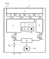
- Fig. 2 shows a further embodiment of another radiometric detector 1, here for ease of understanding, not only identical but also functionally equivalent elements are provided with the same reference numerals as in the above-described embodiment, the description of which can be referenced.
- the radiometric detector 1 of the Fig. 2 a further optoelectronic sensor 3 ', a comparison part 19 and a further malfunction output unit 15'.
- the further optoelectronic sensor 3 ' is designed to convert the light pulses generated by the scintillator 2 into an associated further sensor signal S'.
- the comparison part 19 is designed to compare a further measured variable signal MG 'further processed from the further sensor signal S' with the measured variable signal MG, in particular continuously.
- the comparison part 19 is subjected to the measured variable signal MG after the transmission part 17 and the further measured variable signal MG 'for a further transmission part 17, as indicated by the solid lines in the Fig. 2 displayed.
- the radiometric detector 1 has a further evaluation unit 4 'for further processing of the further sensor signal S' to the further measured variable signal MG ', wherein the further evaluation unit 4' with the further sensor signal S 'of the further optoelectronic sensor 3' is acted upon.
- the further evaluation unit 4 ' may differ from the structure of the evaluation unit 4.
- the further malfunction output unit 15 ' is configured to output a malfunction signal as a function of a comparison result of the comparison part 19.
- the other malfunction output unit 15 ' is in signal communication with the comparing part 19 as indicated by the dotted lines in FIG Fig. 2 displayed.
- the malfunction output unit 15 is configured to output a malfunction signal in optical form by a warning lamp.
- the conversion part 16 of the evaluation unit 4 is defective and the measured variable signal MG is equal to zero, while the further evaluation unit 4 'and the further transmission part 17 are functional and the other measured variable signal MG 'is different from zero.
- the comparison part 19 recognizes that the measured variable signal MG deviates from the further measured variable signal MG'. Consequently, the warning lamp of the other malfunction output unit 15 'outputs a malfunction signal.
- the radiometric detector 1 has a switch 20.
- the switch 20 is in signal communication with the comparison part 19. In case of a malfunction, as it should be present in the example, the switch 20 is open.
- the switch 20 may be closed and the measured variable signal MG, as far as error-free and there is no deviation from the further measured variable signal MG ', are transmitted to the outside.
- the radiometric detector has three or four optoelectronic sensors. Alternatively, it may have two or more than three or four optoelectronic sensors.
- the radiometric detector has a single scintillator.
- the radiometric detector may comprise a plurality of adjacently arranged scintillators, wherein at least one optoelectronic sensor may be optically coupled to each scintillator.
- Several of these independent scintillation modules can be arranged as densely packed as possible in the housing of the radiometric detector.
- the summation part can be configured to form individual sum sensor signals only from the error-free analog sensor signals of the individual scintillation modules and to form from the single sum sensor signals or from these further processed signals a sum sensor signal for obtaining a measured variable signal for the measured variable.
- the amplifier is designed to attenuate the measurement threshold with the gain factor.
- the amplifier may be configured to amplify the sum sensor signal with the gain factor to produce a boosted sum sensor signal.
- the radiometric detector may include an analog-to-digital converter, wherein the analog-to-digital converter may be configured to receive a respective sensor signal or the sum sensor signal or one of the sum sensor signal to digitize further processed signal.
- the analog-to-digital converter may be part of the evaluation unit. The further procedure then takes place digitally in the manner described above.
- the comparator When digitizing the sum sensor signal by means of the analog-to-digital converter can be omitted if necessary, the comparator.
- the evaluation unit, the analog-to-digital converter, the evaluation part, the summation part and / or the comparator can be realized in the form of a microprocessor and associated software.
- the malfunction output unit or the further malfunction output unit may be configured to display a malfunction signal in acoustic form by means of a loudspeaker and / or in the form of an electronic message to a control system for the radiometric detector.
- the invention provides an advantageous radiometric detector for detecting a measured variable, wherein the detector is particularly fail-safe while at the same time simple, space-saving and cost-effective design, without sacrificing the signal-to-noise ratio.
Landscapes
- Physics & Mathematics (AREA)
- General Physics & Mathematics (AREA)
- Health & Medical Sciences (AREA)
- Life Sciences & Earth Sciences (AREA)
- High Energy & Nuclear Physics (AREA)
- Molecular Biology (AREA)
- Spectroscopy & Molecular Physics (AREA)
- Electromagnetism (AREA)
- Chemical & Material Sciences (AREA)
- Fluid Mechanics (AREA)
- Thermal Sciences (AREA)
- Immunology (AREA)
- General Health & Medical Sciences (AREA)
- Pathology (AREA)
- Biochemistry (AREA)
- Analytical Chemistry (AREA)
- Crystallography & Structural Chemistry (AREA)
- Measurement Of Radiation (AREA)
- Testing Or Calibration Of Command Recording Devices (AREA)
Priority Applications (4)
| Application Number | Priority Date | Filing Date | Title |
|---|---|---|---|
| EP15157852.3A EP3064910B1 (fr) | 2015-03-05 | 2015-03-05 | Détecteur radiométrique destiné à la détection d'une grandeur de mesure |
| CN201610227978.0A CN105938201B (zh) | 2015-03-05 | 2016-03-04 | 用于检测测量变量的辐射度检测器 |
| US15/060,917 US9897703B2 (en) | 2015-03-05 | 2016-03-04 | Radiometric detector for detecting a measurement variable |
| US15/877,023 US10180502B2 (en) | 2015-03-05 | 2018-01-22 | Radiometric detector for detecting a measurement variable |
Applications Claiming Priority (1)
| Application Number | Priority Date | Filing Date | Title |
|---|---|---|---|
| EP15157852.3A EP3064910B1 (fr) | 2015-03-05 | 2015-03-05 | Détecteur radiométrique destiné à la détection d'une grandeur de mesure |
Publications (2)
| Publication Number | Publication Date |
|---|---|
| EP3064910A1 true EP3064910A1 (fr) | 2016-09-07 |
| EP3064910B1 EP3064910B1 (fr) | 2020-05-06 |
Family
ID=52629421
Family Applications (1)
| Application Number | Title | Priority Date | Filing Date |
|---|---|---|---|
| EP15157852.3A Active EP3064910B1 (fr) | 2015-03-05 | 2015-03-05 | Détecteur radiométrique destiné à la détection d'une grandeur de mesure |
Country Status (3)
| Country | Link |
|---|---|
| US (2) | US9897703B2 (fr) |
| EP (1) | EP3064910B1 (fr) |
| CN (1) | CN105938201B (fr) |
Cited By (4)
| Publication number | Priority date | Publication date | Assignee | Title |
|---|---|---|---|---|
| EP3462143A1 (fr) | 2017-10-02 | 2019-04-03 | Berthold Technologies GmbH & Co. KG | Appareil de mesure radiométrique et système de mesure radiométrique |
| EP3667260A1 (fr) * | 2018-12-10 | 2020-06-17 | Berthold Technologies GmbH & Co. KG | Appareil de mesure radiométrique |
| CN111521519A (zh) * | 2020-05-09 | 2020-08-11 | 河海大学 | 一种用于测量饱和土中水泥与土比例的探头及方法 |
| WO2024132549A1 (fr) * | 2022-12-19 | 2024-06-27 | Endress+Hauser SE+Co. KG | Détecteur radiométrique |
Families Citing this family (1)
| Publication number | Priority date | Publication date | Assignee | Title |
|---|---|---|---|---|
| JP6623861B2 (ja) * | 2016-03-14 | 2019-12-25 | 株式会社島津製作所 | 放射線検出器およびそれを備えたtof−pet装置 |
Citations (4)
| Publication number | Priority date | Publication date | Assignee | Title |
|---|---|---|---|---|
| DE10132267A1 (de) * | 2001-07-04 | 2003-01-23 | Endress & Hauser Gmbh & Co Kg | Vorrichtung zur Bestimmung und/oder Überwachung der Dichte / des Dichteprofils und/oder Füllstands |
| DE102004007680A1 (de) * | 2004-02-16 | 2005-09-01 | Endress + Hauser Gmbh + Co. Kg | Radiometrisches Meßgerät |
| EP2194362A1 (fr) * | 2008-12-08 | 2010-06-09 | VEGA Grieshaber KG | Mesure de niveau ou de densité par radiométrie |
| EP2378312A1 (fr) * | 2010-04-13 | 2011-10-19 | VEGA Grieshaber KG | Diagnostic de détecteurs radiométriques |
Family Cites Families (3)
| Publication number | Priority date | Publication date | Assignee | Title |
|---|---|---|---|---|
| EP2237073B1 (fr) * | 2009-03-30 | 2012-10-31 | Berthold Technologies GmbH & Co. KG | Procédé et dispositif destinés à la surveillance d'une compensation de dérive automatique |
| CN102539062A (zh) * | 2011-12-29 | 2012-07-04 | 中国燃气涡轮研究院 | 一种传感器温度漂移补偿方法及压力传感器盒 |
| DE102012105922A1 (de) * | 2012-07-03 | 2014-01-09 | Endress + Hauser Gmbh + Co. Kg | Radiometrische Messanordnung und Verfahren zur Detektion von Ansatzbildung in einer radiometrischen Messanordnung |
-
2015
- 2015-03-05 EP EP15157852.3A patent/EP3064910B1/fr active Active
-
2016
- 2016-03-04 CN CN201610227978.0A patent/CN105938201B/zh active Active
- 2016-03-04 US US15/060,917 patent/US9897703B2/en not_active Expired - Fee Related
-
2018
- 2018-01-22 US US15/877,023 patent/US10180502B2/en active Active
Patent Citations (4)
| Publication number | Priority date | Publication date | Assignee | Title |
|---|---|---|---|---|
| DE10132267A1 (de) * | 2001-07-04 | 2003-01-23 | Endress & Hauser Gmbh & Co Kg | Vorrichtung zur Bestimmung und/oder Überwachung der Dichte / des Dichteprofils und/oder Füllstands |
| DE102004007680A1 (de) * | 2004-02-16 | 2005-09-01 | Endress + Hauser Gmbh + Co. Kg | Radiometrisches Meßgerät |
| EP2194362A1 (fr) * | 2008-12-08 | 2010-06-09 | VEGA Grieshaber KG | Mesure de niveau ou de densité par radiométrie |
| EP2378312A1 (fr) * | 2010-04-13 | 2011-10-19 | VEGA Grieshaber KG | Diagnostic de détecteurs radiométriques |
Cited By (7)
| Publication number | Priority date | Publication date | Assignee | Title |
|---|---|---|---|---|
| EP3462143A1 (fr) | 2017-10-02 | 2019-04-03 | Berthold Technologies GmbH & Co. KG | Appareil de mesure radiométrique et système de mesure radiométrique |
| EP3667260A1 (fr) * | 2018-12-10 | 2020-06-17 | Berthold Technologies GmbH & Co. KG | Appareil de mesure radiométrique |
| US11029422B2 (en) | 2018-12-10 | 2021-06-08 | Berthold Technologies Gmbh & Co. Kg | Radiometric measuring apparatus |
| EP3667260B1 (fr) * | 2018-12-10 | 2022-07-13 | Berthold Technologies GmbH & Co. KG | Appareil de mesure radiométrique |
| CN111521519A (zh) * | 2020-05-09 | 2020-08-11 | 河海大学 | 一种用于测量饱和土中水泥与土比例的探头及方法 |
| CN111521519B (zh) * | 2020-05-09 | 2021-09-17 | 河海大学 | 一种用于测量饱和土中水泥与土比例的探头及方法 |
| WO2024132549A1 (fr) * | 2022-12-19 | 2024-06-27 | Endress+Hauser SE+Co. KG | Détecteur radiométrique |
Also Published As
| Publication number | Publication date |
|---|---|
| CN105938201A (zh) | 2016-09-14 |
| EP3064910B1 (fr) | 2020-05-06 |
| US20180143330A1 (en) | 2018-05-24 |
| US10180502B2 (en) | 2019-01-15 |
| US9897703B2 (en) | 2018-02-20 |
| US20160259066A1 (en) | 2016-09-08 |
| CN105938201B (zh) | 2019-06-28 |
Similar Documents
| Publication | Publication Date | Title |
|---|---|---|
| EP3064910B1 (fr) | Détecteur radiométrique destiné à la détection d'une grandeur de mesure | |
| EP2603907B1 (fr) | Évaluation de signaux de lumière diffusée dans le cas d'un avertisseur optique de danger, et émission d'un avertissement de présence de poussière /vapeur ou d'une alarme incendie | |
| EP2237073B1 (fr) | Procédé et dispositif destinés à la surveillance d'une compensation de dérive automatique | |
| DE10357187A1 (de) | Verfahren zum Betrieb eines zählenden Strahlungsdetektors mit verbesserter Linearität | |
| EP2194362B1 (fr) | Mesure de niveau ou de densité par radiométrie | |
| DE102016116426B4 (de) | Verfahren zum Verarbeiten eines Single-Edge-Nibble-Transmission-Signals, Datenempfangsvorrichtung und Datenübertragungseinrichtung | |
| EP2187175A2 (fr) | Convertisseur de mesure | |
| WO1993003530A1 (fr) | Procede et dispositif de reconnaissance de defauts dans des systemes convertisseurs | |
| EP2867624B1 (fr) | Detecteur d'angle de rotation multi-canaux | |
| WO2020070311A1 (fr) | Capteur d'imagerie | |
| DE102007055521C5 (de) | Vorrichtung zur Überwachung eines Überwachungsbereichs | |
| DE102018117878A1 (de) | Sicherheitslichtgitter | |
| EP2698649A1 (fr) | Capteur de surveillance doté d'un contrôle automatique | |
| DE102017112789A1 (de) | Optoelektronische Detektionsvorrichtung für ein Kraftfahrzeug mit über denselben Signalverarbeitungspfad testbaren Sende- und Empfangsweg und Verfahren zum Betreiben einer solchen Detektionsvorrichtung | |
| DE202007007290U1 (de) | Optoelektronische Sensoranordnung | |
| DE19718390A1 (de) | Opto-elektronischer Sensor | |
| DE102014225399B4 (de) | Rauschunterdrückung bei der Korrektur von Artefakten von CT-Bildern | |
| WO2013174490A1 (fr) | Circuit d'entrée de signaux analogiques avec un certain nombre de canaux de détection de signaux analogiques | |
| DE4440281C2 (de) | Einrichtung zur optischen Erfassung von Störlichtbogenentladungen | |
| EP3623849B1 (fr) | Capteur optique | |
| EP1927868A2 (fr) | Capteur optoélectrique | |
| EP3667260B1 (fr) | Appareil de mesure radiométrique | |
| DE102007009141A1 (de) | Sicherheitsvorrichtung und Sicherheitsverfahren mit mehreren Verarbeitungsstufen | |
| EP4411427B1 (fr) | Rideau lumineux | |
| DE102014213047A1 (de) | Röntgendetektor mit Hochspannungsversorgung und bildgebendes Medizingerät |
Legal Events
| Date | Code | Title | Description |
|---|---|---|---|
| PUAI | Public reference made under article 153(3) epc to a published international application that has entered the european phase |
Free format text: ORIGINAL CODE: 0009012 |
|
| AK | Designated contracting states |
Kind code of ref document: A1 Designated state(s): AL AT BE BG CH CY CZ DE DK EE ES FI FR GB GR HR HU IE IS IT LI LT LU LV MC MK MT NL NO PL PT RO RS SE SI SK SM TR |
|
| AX | Request for extension of the european patent |
Extension state: BA ME |
|
| STAA | Information on the status of an ep patent application or granted ep patent |
Free format text: STATUS: REQUEST FOR EXAMINATION WAS MADE |
|
| 17P | Request for examination filed |
Effective date: 20170118 |
|
| RBV | Designated contracting states (corrected) |
Designated state(s): AL AT BE BG CH CY CZ DE DK EE ES FI FR GB GR HR HU IE IS IT LI LT LU LV MC MK MT NL NO PL PT RO RS SE SI SK SM TR |
|
| GRAP | Despatch of communication of intention to grant a patent |
Free format text: ORIGINAL CODE: EPIDOSNIGR1 |
|
| STAA | Information on the status of an ep patent application or granted ep patent |
Free format text: STATUS: GRANT OF PATENT IS INTENDED |
|
| RIC1 | Information provided on ipc code assigned before grant |
Ipc: G01T 1/20 20060101ALI20191206BHEP Ipc: G01F 23/288 20060101AFI20191206BHEP Ipc: G01N 9/24 20060101ALI20191206BHEP |
|
| INTG | Intention to grant announced |
Effective date: 20200103 |
|
| GRAS | Grant fee paid |
Free format text: ORIGINAL CODE: EPIDOSNIGR3 |
|
| GRAA | (expected) grant |
Free format text: ORIGINAL CODE: 0009210 |
|
| STAA | Information on the status of an ep patent application or granted ep patent |
Free format text: STATUS: THE PATENT HAS BEEN GRANTED |
|
| AK | Designated contracting states |
Kind code of ref document: B1 Designated state(s): AL AT BE BG CH CY CZ DE DK EE ES FI FR GB GR HR HU IE IS IT LI LT LU LV MC MK MT NL NO PL PT RO RS SE SI SK SM TR |
|
| REG | Reference to a national code |
Ref country code: GB Ref legal event code: FG4D Free format text: NOT ENGLISH |
|
| REG | Reference to a national code |
Ref country code: CH Ref legal event code: EP Ref country code: AT Ref legal event code: REF Ref document number: 1267517 Country of ref document: AT Kind code of ref document: T Effective date: 20200515 |
|
| REG | Reference to a national code |
Ref country code: IE Ref legal event code: FG4D Free format text: LANGUAGE OF EP DOCUMENT: GERMAN |
|
| REG | Reference to a national code |
Ref country code: DE Ref legal event code: R096 Ref document number: 502015012478 Country of ref document: DE |
|
| REG | Reference to a national code |
Ref country code: LT Ref legal event code: MG4D |
|
| REG | Reference to a national code |
Ref country code: NL Ref legal event code: MP Effective date: 20200506 |
|
| PG25 | Lapsed in a contracting state [announced via postgrant information from national office to epo] |
Ref country code: NO Free format text: LAPSE BECAUSE OF FAILURE TO SUBMIT A TRANSLATION OF THE DESCRIPTION OR TO PAY THE FEE WITHIN THE PRESCRIBED TIME-LIMIT Effective date: 20200806 Ref country code: IS Free format text: LAPSE BECAUSE OF FAILURE TO SUBMIT A TRANSLATION OF THE DESCRIPTION OR TO PAY THE FEE WITHIN THE PRESCRIBED TIME-LIMIT Effective date: 20200906 Ref country code: GR Free format text: LAPSE BECAUSE OF FAILURE TO SUBMIT A TRANSLATION OF THE DESCRIPTION OR TO PAY THE FEE WITHIN THE PRESCRIBED TIME-LIMIT Effective date: 20200807 Ref country code: LT Free format text: LAPSE BECAUSE OF FAILURE TO SUBMIT A TRANSLATION OF THE DESCRIPTION OR TO PAY THE FEE WITHIN THE PRESCRIBED TIME-LIMIT Effective date: 20200506 Ref country code: SE Free format text: LAPSE BECAUSE OF FAILURE TO SUBMIT A TRANSLATION OF THE DESCRIPTION OR TO PAY THE FEE WITHIN THE PRESCRIBED TIME-LIMIT Effective date: 20200506 Ref country code: FI Free format text: LAPSE BECAUSE OF FAILURE TO SUBMIT A TRANSLATION OF THE DESCRIPTION OR TO PAY THE FEE WITHIN THE PRESCRIBED TIME-LIMIT Effective date: 20200506 Ref country code: PT Free format text: LAPSE BECAUSE OF FAILURE TO SUBMIT A TRANSLATION OF THE DESCRIPTION OR TO PAY THE FEE WITHIN THE PRESCRIBED TIME-LIMIT Effective date: 20200907 |
|
| PG25 | Lapsed in a contracting state [announced via postgrant information from national office to epo] |
Ref country code: BG Free format text: LAPSE BECAUSE OF FAILURE TO SUBMIT A TRANSLATION OF THE DESCRIPTION OR TO PAY THE FEE WITHIN THE PRESCRIBED TIME-LIMIT Effective date: 20200806 Ref country code: HR Free format text: LAPSE BECAUSE OF FAILURE TO SUBMIT A TRANSLATION OF THE DESCRIPTION OR TO PAY THE FEE WITHIN THE PRESCRIBED TIME-LIMIT Effective date: 20200506 Ref country code: LV Free format text: LAPSE BECAUSE OF FAILURE TO SUBMIT A TRANSLATION OF THE DESCRIPTION OR TO PAY THE FEE WITHIN THE PRESCRIBED TIME-LIMIT Effective date: 20200506 Ref country code: RS Free format text: LAPSE BECAUSE OF FAILURE TO SUBMIT A TRANSLATION OF THE DESCRIPTION OR TO PAY THE FEE WITHIN THE PRESCRIBED TIME-LIMIT Effective date: 20200506 |
|
| PG25 | Lapsed in a contracting state [announced via postgrant information from national office to epo] |
Ref country code: AL Free format text: LAPSE BECAUSE OF FAILURE TO SUBMIT A TRANSLATION OF THE DESCRIPTION OR TO PAY THE FEE WITHIN THE PRESCRIBED TIME-LIMIT Effective date: 20200506 Ref country code: NL Free format text: LAPSE BECAUSE OF FAILURE TO SUBMIT A TRANSLATION OF THE DESCRIPTION OR TO PAY THE FEE WITHIN THE PRESCRIBED TIME-LIMIT Effective date: 20200506 |
|
| PG25 | Lapsed in a contracting state [announced via postgrant information from national office to epo] |
Ref country code: DK Free format text: LAPSE BECAUSE OF FAILURE TO SUBMIT A TRANSLATION OF THE DESCRIPTION OR TO PAY THE FEE WITHIN THE PRESCRIBED TIME-LIMIT Effective date: 20200506 Ref country code: ES Free format text: LAPSE BECAUSE OF FAILURE TO SUBMIT A TRANSLATION OF THE DESCRIPTION OR TO PAY THE FEE WITHIN THE PRESCRIBED TIME-LIMIT Effective date: 20200506 Ref country code: IT Free format text: LAPSE BECAUSE OF FAILURE TO SUBMIT A TRANSLATION OF THE DESCRIPTION OR TO PAY THE FEE WITHIN THE PRESCRIBED TIME-LIMIT Effective date: 20200506 Ref country code: RO Free format text: LAPSE BECAUSE OF FAILURE TO SUBMIT A TRANSLATION OF THE DESCRIPTION OR TO PAY THE FEE WITHIN THE PRESCRIBED TIME-LIMIT Effective date: 20200506 Ref country code: CZ Free format text: LAPSE BECAUSE OF FAILURE TO SUBMIT A TRANSLATION OF THE DESCRIPTION OR TO PAY THE FEE WITHIN THE PRESCRIBED TIME-LIMIT Effective date: 20200506 Ref country code: EE Free format text: LAPSE BECAUSE OF FAILURE TO SUBMIT A TRANSLATION OF THE DESCRIPTION OR TO PAY THE FEE WITHIN THE PRESCRIBED TIME-LIMIT Effective date: 20200506 Ref country code: SM Free format text: LAPSE BECAUSE OF FAILURE TO SUBMIT A TRANSLATION OF THE DESCRIPTION OR TO PAY THE FEE WITHIN THE PRESCRIBED TIME-LIMIT Effective date: 20200506 |
|
| REG | Reference to a national code |
Ref country code: DE Ref legal event code: R097 Ref document number: 502015012478 Country of ref document: DE |
|
| PG25 | Lapsed in a contracting state [announced via postgrant information from national office to epo] |
Ref country code: SK Free format text: LAPSE BECAUSE OF FAILURE TO SUBMIT A TRANSLATION OF THE DESCRIPTION OR TO PAY THE FEE WITHIN THE PRESCRIBED TIME-LIMIT Effective date: 20200506 Ref country code: PL Free format text: LAPSE BECAUSE OF FAILURE TO SUBMIT A TRANSLATION OF THE DESCRIPTION OR TO PAY THE FEE WITHIN THE PRESCRIBED TIME-LIMIT Effective date: 20200506 |
|
| PLBE | No opposition filed within time limit |
Free format text: ORIGINAL CODE: 0009261 |
|
| STAA | Information on the status of an ep patent application or granted ep patent |
Free format text: STATUS: NO OPPOSITION FILED WITHIN TIME LIMIT |
|
| 26N | No opposition filed |
Effective date: 20210209 |
|
| PG25 | Lapsed in a contracting state [announced via postgrant information from national office to epo] |
Ref country code: SI Free format text: LAPSE BECAUSE OF FAILURE TO SUBMIT A TRANSLATION OF THE DESCRIPTION OR TO PAY THE FEE WITHIN THE PRESCRIBED TIME-LIMIT Effective date: 20200506 |
|
| PG25 | Lapsed in a contracting state [announced via postgrant information from national office to epo] |
Ref country code: MC Free format text: LAPSE BECAUSE OF FAILURE TO SUBMIT A TRANSLATION OF THE DESCRIPTION OR TO PAY THE FEE WITHIN THE PRESCRIBED TIME-LIMIT Effective date: 20200506 |
|
| REG | Reference to a national code |
Ref country code: CH Ref legal event code: PL |
|
| GBPC | Gb: european patent ceased through non-payment of renewal fee |
Effective date: 20210305 |
|
| REG | Reference to a national code |
Ref country code: BE Ref legal event code: MM Effective date: 20210331 |
|
| PG25 | Lapsed in a contracting state [announced via postgrant information from national office to epo] |
Ref country code: IE Free format text: LAPSE BECAUSE OF NON-PAYMENT OF DUE FEES Effective date: 20210305 Ref country code: FR Free format text: LAPSE BECAUSE OF NON-PAYMENT OF DUE FEES Effective date: 20210331 Ref country code: GB Free format text: LAPSE BECAUSE OF NON-PAYMENT OF DUE FEES Effective date: 20210305 Ref country code: CH Free format text: LAPSE BECAUSE OF NON-PAYMENT OF DUE FEES Effective date: 20210331 Ref country code: LU Free format text: LAPSE BECAUSE OF NON-PAYMENT OF DUE FEES Effective date: 20210305 Ref country code: LI Free format text: LAPSE BECAUSE OF NON-PAYMENT OF DUE FEES Effective date: 20210331 |
|
| REG | Reference to a national code |
Ref country code: AT Ref legal event code: MM01 Ref document number: 1267517 Country of ref document: AT Kind code of ref document: T Effective date: 20210305 |
|
| PG25 | Lapsed in a contracting state [announced via postgrant information from national office to epo] |
Ref country code: BE Free format text: LAPSE BECAUSE OF NON-PAYMENT OF DUE FEES Effective date: 20210331 |
|
| PG25 | Lapsed in a contracting state [announced via postgrant information from national office to epo] |
Ref country code: AT Free format text: LAPSE BECAUSE OF NON-PAYMENT OF DUE FEES Effective date: 20210305 |
|
| PG25 | Lapsed in a contracting state [announced via postgrant information from national office to epo] |
Ref country code: HU Free format text: LAPSE BECAUSE OF FAILURE TO SUBMIT A TRANSLATION OF THE DESCRIPTION OR TO PAY THE FEE WITHIN THE PRESCRIBED TIME-LIMIT; INVALID AB INITIO Effective date: 20150305 |
|
| PG25 | Lapsed in a contracting state [announced via postgrant information from national office to epo] |
Ref country code: CY Free format text: LAPSE BECAUSE OF FAILURE TO SUBMIT A TRANSLATION OF THE DESCRIPTION OR TO PAY THE FEE WITHIN THE PRESCRIBED TIME-LIMIT Effective date: 20200506 |
|
| PG25 | Lapsed in a contracting state [announced via postgrant information from national office to epo] |
Ref country code: MK Free format text: LAPSE BECAUSE OF FAILURE TO SUBMIT A TRANSLATION OF THE DESCRIPTION OR TO PAY THE FEE WITHIN THE PRESCRIBED TIME-LIMIT Effective date: 20200506 |
|
| PG25 | Lapsed in a contracting state [announced via postgrant information from national office to epo] |
Ref country code: TR Free format text: LAPSE BECAUSE OF FAILURE TO SUBMIT A TRANSLATION OF THE DESCRIPTION OR TO PAY THE FEE WITHIN THE PRESCRIBED TIME-LIMIT Effective date: 20200506 |
|
| PG25 | Lapsed in a contracting state [announced via postgrant information from national office to epo] |
Ref country code: MT Free format text: LAPSE BECAUSE OF FAILURE TO SUBMIT A TRANSLATION OF THE DESCRIPTION OR TO PAY THE FEE WITHIN THE PRESCRIBED TIME-LIMIT Effective date: 20200506 |
|
| PGFP | Annual fee paid to national office [announced via postgrant information from national office to epo] |
Ref country code: DE Payment date: 20260324 Year of fee payment: 12 |