EP3064938A1 - Dispositif d'analyse - Google Patents
Dispositif d'analyse Download PDFInfo
- Publication number
- EP3064938A1 EP3064938A1 EP14858696.9A EP14858696A EP3064938A1 EP 3064938 A1 EP3064938 A1 EP 3064938A1 EP 14858696 A EP14858696 A EP 14858696A EP 3064938 A1 EP3064938 A1 EP 3064938A1
- Authority
- EP
- European Patent Office
- Prior art keywords
- dust
- hole
- discharge path
- analysis apparatus
- introduction part
- Prior art date
- Legal status (The legal status is an assumption and is not a legal conclusion. Google has not performed a legal analysis and makes no representation as to the accuracy of the status listed.)
- Granted
Links
Images


Classifications
-
- G—PHYSICS
- G01—MEASURING; TESTING
- G01N—INVESTIGATING OR ANALYSING MATERIALS BY DETERMINING THEIR CHEMICAL OR PHYSICAL PROPERTIES
- G01N1/00—Sampling; Preparing specimens for investigation
- G01N1/28—Preparing specimens for investigation including physical details of (bio-)chemical methods covered elsewhere, e.g. G01N33/50, C12Q
- G01N1/34—Purifying; Cleaning
-
- G—PHYSICS
- G01—MEASURING; TESTING
- G01N—INVESTIGATING OR ANALYSING MATERIALS BY DETERMINING THEIR CHEMICAL OR PHYSICAL PROPERTIES
- G01N1/00—Sampling; Preparing specimens for investigation
- G01N1/28—Preparing specimens for investigation including physical details of (bio-)chemical methods covered elsewhere, e.g. G01N33/50, C12Q
- G01N1/44—Sample treatment involving radiation, e.g. heat
-
- G—PHYSICS
- G01—MEASURING; TESTING
- G01N—INVESTIGATING OR ANALYSING MATERIALS BY DETERMINING THEIR CHEMICAL OR PHYSICAL PROPERTIES
- G01N33/00—Investigating or analysing materials by specific methods not covered by groups G01N1/00 - G01N31/00
- G01N33/0004—Gaseous mixtures, e.g. polluted air
- G01N33/0009—General constructional details of gas analysers, e.g. portable test equipment
- G01N33/0011—Sample conditioning
- G01N33/0016—Sample conditioning by regulating a physical variable, e.g. pressure or temperature
-
- F—MECHANICAL ENGINEERING; LIGHTING; HEATING; WEAPONS; BLASTING
- F27—FURNACES; KILNS; OVENS; RETORTS
- F27D—DETAILS OR ACCESSORIES OF FURNACES, KILNS, OVENS OR RETORTS, IN SO FAR AS THEY ARE OF KINDS OCCURRING IN MORE THAN ONE KIND OF FURNACE
- F27D19/00—Arrangements of controlling devices
- F27D2019/0006—Monitoring the characteristics (composition, quantities, temperature, pressure) of at least one of the gases of the kiln atmosphere and using it as a controlling value
- F27D2019/0012—Monitoring the composition of the atmosphere or of one of their components
-
- G—PHYSICS
- G01—MEASURING; TESTING
- G01N—INVESTIGATING OR ANALYSING MATERIALS BY DETERMINING THEIR CHEMICAL OR PHYSICAL PROPERTIES
- G01N1/00—Sampling; Preparing specimens for investigation
- G01N1/02—Devices for withdrawing samples
- G01N1/22—Devices for withdrawing samples in the gaseous state
- G01N1/2247—Sampling from a flowing stream of gas
- G01N2001/227—Sampling from a flowing stream of gas separating gas from solid, e.g. filter
-
- G—PHYSICS
- G01—MEASURING; TESTING
- G01N—INVESTIGATING OR ANALYSING MATERIALS BY DETERMINING THEIR CHEMICAL OR PHYSICAL PROPERTIES
- G01N31/00—Investigating or analysing non-biological materials by the use of the chemical methods specified in the subgroup; Apparatus specially adapted for such methods
- G01N31/12—Investigating or analysing non-biological materials by the use of the chemical methods specified in the subgroup; Apparatus specially adapted for such methods using combustion
Definitions
- the present invention relates to an analysis apparatus such as an elemental analysis apparatus adapted to analyze elements such as carbon (C) and sulfur (S) contained in a sample such as steel, nonferrous metal, or ceramic.
- an analysis apparatus such as an elemental analysis apparatus adapted to analyze elements such as carbon (C) and sulfur (S) contained in a sample such as steel, nonferrous metal, or ceramic.
- this sort of elemental analysis apparatus there is one adapted to place in a heating furnace a crucible containing a sample, apply high frequency AC voltage to a coil provided around the crucible to heat and burn the sample in the crucible by high frequency induction heating, and from gas produced thereby, analyze elements contained in the sample.
- the above-described elemental analysis apparatus is configured to include a dust suction mechanism as well as sucking dust through a through-hole formed on the side circumferential surface of the heating furnace to discharge the dust because dust such as soot is produced by burning the sample and when the measurement gas is adsorbed by the dust, a measurement error occurs.
- Patent Literature 1 Japanese Unexamined Patent Publication JP-A2000-266741
- the present invention is made in order to solve the above-described problem, and a main object thereof is to surely discharge dust produced in a heating furnace to accurately perform analysis.
- an analysis apparatus is an analysis apparatus that heats a sample in a sample containing part and analyzes gas produced thereby, and includes: a dust introduction part that has a through-hole formed penetrating in a vertical direction and introduces dust produced in the sample containing part into the through-hole; a dust containing part that contains the dust discharged through the through-hole; and a dust discharge path of which one end is connected to the dust introduction part to communicatively connect to the through-hole and the other end is connected to the dust containing part, in which the dust discharge path is linearly formed along the vertical direction from the one end to the other end.
- the dust discharge path is linearly formed along the vertical direction from the one end to the other end, the dust discharged through the through-hole can be discharged without remaining in the dust discharge path.
- the analysis apparatus includes an up/down movement mechanism adapted to integrally move up or down the dust introduction part, the dust discharge path, and the dust containing part.
- the analysis apparatus includes: a supporting part that supports the dust introduction part; and a driving part that has a shaft member connected to the supporting part and moves up or down the supporting part, and the shaft member is arranged separately from the dust introduction part in a horizontal direction by a predetermined distance.
- the through-hole is formed in a rotating body shape.
- the analysis apparatus further includes an open/close mechanism that is provided in the dust discharge path and switches an open/close state of the dust discharge path.
- the cylinder when the dust introduction part comes close to the sample containing part, the cylinder extends in its axial direction, and when attempting to align the axes of the dust introduction part and the sample containing part in this state, the cylinder makes a swinging motion to make it difficult to accurately align the axes.
- the cylinder in the case where the cylinder is arranged separately from the dust introduction part by the predetermined distance, when aligning the axes, the cylinder makes a swinging motion at a position eccentric to the dust introduction part and the sample containing part, further increasing difficulty.
- the cylinder makes a swing motion when aligning the axes of the dust introduction part and the sample containing part, the swing propagates to, for example, an actuator and the like constituting the cylinder to place a load on the actuator and the like, thus reducing the life of the apparatus.
- the driving part further has a driving part main body into or out of which the shaft member moves; the shaft member moves into the driving part main body, and thereby the dust introduction part moves in a direction to block a downward opening formed in the sample containing part; and the shaft member moves out of the driving part main body, and thereby the dust introduction part moves in a direction to open the opening.
- the dust produced in the sample containing part can be surely discharged, and thereby a measurement error due to the attachment of the gas to dust can be made unlikely to occur, thus making it possible to accurately perform the analysis.
- An elemental analysis apparatus 100 is one that for example, heats and burns a sample X such as metal, and from gas produced thereby, analyzes elements such as carbon (C) and sulfur (S) contained in the sample X.
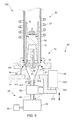
- the elemental analysis apparatus 100 is one including: a heating furnace 10 as a sample containing part in which a crucible R containing the sample X is placed; a heating mechanism 20 adapted to heat the sample X; an unillustrated gas analyzer adapted to analyze the gas produced by heating and burning the sample X; a dust introduction part30 into which dust produced by burning the sample X is introduced; and a dust discharge mechanism 40 adapted to discharge the dust from inside the heating furnace 10.
- the heating furnace 10 is configured to burn the sample X inside, and lead the gas produced thereby to the unillustrated gas analyzer, and as illustrated in Figs. 1 and 2 , is formed in a substantially tubular shape as well as having an opening 11 formed vertically downward.
- the heating furnace 10 includes: a furnace main body 12 formed in a substantially circular tube shape; and a block body 13 that is provided below the furnace main body 12 and has a communicative connection hole 13a communicatively connected to the inside of the furnace main body 12 and formed penetrating in the vertical direction.
- the opening 11 of the heating furnace 10 is one that is formed as a downward opening of the communicative connection hole 13a in a circular shape, and formed such that the central axis of the opening 11 and the tube axis of the furnace main body 12 coincide with each other.
- the crucible R is contained on a placement table 14.
- the placement table 14 is provided vertically movable along the tube axial direction of the furnace main body 12 inside the furnace main body 12, and in the present embodiment, configured to be moved up or down by the below-described up/down movement mechanism 50 between a heating position where the sample X in the crucible R is heated inside the heating furnace 10 and an attachment/detachment position where the crucible R is positioned outside the heating furnace 10 and attached on or detached from the placement table 14.
- the crucible R is one that contains the sample X inside and is attached on the placement table 14, and in the present embodiment, made of a magnetic material such as ceramic having an electrically conductive heating element.
- the heating mechanism 20 is an induction current generating mechanism adapted to generate induction current in the sample X contained in the crucible R by high frequency induction heating, and specifically one including a coil 21 and an unillustrated power supply adapted to apply high frequency AC voltage to the coil 21.
- the coil 21 is provided along the outer circumference of the furnace main body 12, and the height of the placement table 14 is set such that when the high frequency AC voltage is applied to the coil 21, the crucible R is positioned inside the coil 21.
- the electrically conductive heating element included in the crucible R generates heat by the high frequency induction heating to heat the sample X in the crucible R.
- the unillustrated gas analyzer is one that analyzes the gas led to the gas analyzer and obtains the contents of respective components contained in the sample X, and in the present embodiment, one that performs the analysis using, for example, a non-dispersive infrared absorption method (NDIR method).
- the gas analyzer has an unillustrated non-dispersive infrared detector, and is one that detects CO 2 , CO, SO 2 , and the like contained in the gas to thereby obtain the contents of carbon (C), sulfur (S), and the like contained in the sample X.
- the dust introduction part 30 is one that has a through-hole 3a formed penetrating in the vertical direction, and is also one that is provided so as to close the vertically downward opening 11 formed in the heating furnace 10 in a state where the placement table 14 is in the heating position, and introduces the dust produced by burning the sample X into the through-hole 3a. More specifically, the dust introduction part 30 in the present embodiment is arranged with the upper part of the dust introduction part 30 being fitted into the communicative connection hole 13a formed in the block body 13 via, for example, a seal member.
- the dust introduction part 30 is formed in a block body shape, and in the center thereof, the through-hole 3a that penetrates through the dust introduction part 30 in the vertical direction and communicatively connects to the inside of the heating furnace 10 is formed, and also an introduction surface 31 adapted to introduce the dust into the through-hole 3a to discharge it is formed.
- the through-hole 3a is formed in a rotating body shape, and also formed such that the rotational axis thereof coincide with the tube axis of the heating furnace 10, i.e., with the central axis of the opening 11. More specifically, the through-hole 3a is a space surrounded by the inner circumferential surface of the dust introduction part 30, and in the present embodiment, formed as a space surrounded by: a first inner circumferential surface 311, which is formed in an inverted truncated conical shape of which the diameter decreases vertically downward; and a second inner circumferential surface 312, which is formed continuously with the first inner circumferential surface 311, linearly extends vertically downward, and has a uniform circular-shaped cross section.
- the introduction surface 31 is symmetrically formed with the through-hole 3a as the center, and in the present embodiment, a tilted surface formed in a rotating body shape with the tube axis of the heating furnace 10 as the central axis, of which at least part is formed of the first inner circumferential surface 311.
- the introduction surface 31 is formed in an annular shape as viewed from vertically above.
- the above-described configuration and activation of the below-described dust discharge mechanism 40 make it possible to create a substantially uniform flow from the heating furnace 10 toward the through-hole 3a, and discharge the dust through the through-hole 3a. That is, the dust flow toward the through-hole 3a from a dust production part (crucible R and the like) where the dust is produced is rotationally symmetric on a cross section along the vertical direction.
- the dust introduction part 30 is fixed with the above-described placement table 14, and the present embodiment is configured such that the dust introduction part 30 and the placement table 14 are connected to each other via a connecting member 60 provided on the inner circumferential surface of the dust introduction part 30 and make the up/down movement integrally.
- the connecting member 60 is one that is formed in a flat plate shape, and formed with multiple holes 61 penetrating in the thickness direction.
- the multiple holes 61 are symmetrically positioned with reference to the center of the connecting member 60 as well as being formed along the circumferential direction so as to make the distance between any adjacent two of the holes 61 constant, and it is configured that the dust produced in the heating furnace 10 passes through the holes 61 and are introduced into the through-hole 3a.
- the dust introduction part 30 configured as described above is provided with the up/down movement mechanism 50 adapted to move up or down the dust introduction part 30 along the vertical direction.
- the up/down movement mechanism 50 is one including: a supporting part 51 that supports the dust introduction part 30; and a driving part 52 that has a shaft member 521 connected to the supporting part 51 and moves up or down the supporting part 51 along the vertical direction.
- the supporting part 51 is one configured to be able to arrange the shaft member 521 separately from the dust introduction part 30 in the horizontal direction, and has: a first plate member 511 that extends in the horizontal direction and is formed in a flat plate shape; a connecting plate 513 that is connected to the first plate member 511 at the lower end thereof and upright from the first plate member 511; and a second plate member 512 that extends from the upper end of the connecting plate 513 in the horizontal direction toward the side opposite to the first plate member 511.
- the first plate member 511, the second plate member 512, and the connecting member 513 are integrally formed.
- the first plate member 511 is one adapted to support the dust introduction part 30, and fixed with the dust introduction part 30 by, for example, unillustrated screws or the like.
- the second plate member 512 is positioned on the vertically upper side separately from the first plate member 511 by a predetermined distance, and supported by the shaft member 521.
- the driving part 52 is one that moves up or down the supporting part 51 along the vertical direction at a position offset from the dust introduction part 30 in the horizontal direction.
- the driving part 52 is configured to move up or down the shaft member 521 supporting the second plate member 512, and in the present embodiment, uses a cylinder.
- the shaft member 521 is arranged separately from the dust introduction part 30 in the horizontal direction keeping a distance preventing overlap with at least dust introduction part 30 as viewed from vertically below.
- the central axis of the shaft member 521 is arranged separately in the horizontal direction from each of the central axis of the dust introduction part 30, the rotational axis of the through-hole 3a, and the tube axis of the heating furnace 10. That is, the shaft member 521 is arranged at a position preventing overlap with the opening 11 of the heating furnace 10, the dust introduction part 30, and the below-described dust discharge path 41a as viewed from vertically below, and this makes it possible to arrange the below-described dust containing part 43 vertically below the opening 11 and the dust introduction part 30.
- the shaft member 521 of the driving part 52 moves up or down the supporting part 51 along the vertical direction, and thereby the up/down mechanism 50 configured as described can move up or down the dust introduction part 30 supported by the supporting part 51 along the vertical direction.
- the dust introduction part 30 is connected to the placement table 14 via the connecting member 60, and therefore the placement table 14 moves up or down together with the dust introduction part 30.
- the up/down movement mechanism 50 is configured to move up or down the dust introduction part 30 as the shaft member 521 moves up or down, and also move up or down the crucible R placed on the placement table 14 between the heating position and the attachment/detachment position.
- the dust discharge mechanism 40 is one that discharges the dust produced in the heating furnace 10 from the heating furnace 10, and includes: a dust discharge path forming member 41 that forms the dust discharge path 41a communicatively connecting to the through-hole 3a; an open/clos mechanism 42 that is provided in the dust discharge path forming member 41 to switch an open/close state of the dust discharge path 41a; the dust containing part 43 that is provided on the downstream side of the dust discharge path 41a to contain the dust discharged through the dust discharge path 41a; and a suction mechanism 44 that is connected to the dust containing part 43 to suck air inside the dust containing part 43.
- the dust discharge path forming member 41 is one adapted to discharge the dust vertically downward, and as illustrated in Fig. 1 , also one that forms the dust discharge path 41a inside which the dust flows and is formed in a straight tube shape. More specifically, the dust discharge path forming member 41 is one that is formed of resin or the like and has elasticity, and in the present embodiment, a silicon tube such as a Fluran tube.
- the dust discharge path forming member 41 is configured such that the outside diameter thereof is equal to the opening size of the second inner circumferential surface 312 of the dust introduction part 30, and one end part 411 of the dust discharge forming member 41 is fitted to the second inner circumferential surface 312 without backlash to communicatively connect the dust discharge path 41a and the through-hole 3a to each other. Also, the other end part 412 of the dust discharge path forming member 41 is connected to the below-described dust containing part 43.
- the dust discharge forming member 41 in the present embodiment is configured to move up or down integrally with the dust introduction part 30 along with the up/down movement of the dust introduction part 30 in a state where the one end part 411 is fitted to the second inner circumferential surface 312.
- the dust discharge path 41a is one of which one end is connected to the dust introduction part 30 to communicatively connect to the through-hole 3a and also the other end is connected to the dust containing part 43 to lead the dust to the dust containing part 43 through the through-hole 3a, and in the present embodiment, linearly formed along the vertical direction from the one end to the other end.
- the above-described dust discharge path forming member 41 is provided with the open/close mechanism 42 adapted to switch the dust discharge path 41a to the open state or the close state.
- the open/close mechanism 42 in the present embodiment is one that is controlled by an unillustrated control part so as to, when performing the analysis, switch the dust discharge path 41a to the close state, and when discharging the dust, switch the dust discharge path 41a to the open state.
- the open/close mechanism 42 uses a pinch valve, and is configured to switch the dust discharge path 41a from the open state to the close state by crushing the silicon tube as the dust discharge path forming member 41. In addition, while the open/close mechanism 42 switches the dust discharge path 41a to the close state, dust deposits at a position where the dust discharge path 41a is crushed.
- the dust containing part 43 is provided on the downstream side of the dust discharge path 41a, and in the present embodiment, for example, a substantially rectangular parallelepiped shaped dust box arranged vertically below the through-hole 3a of the dust introduction part 30.
- the dust containing part 43 is configured to be attachable to or detachable from the other end part 412 of the dust discharge path forming member 41, and in a state of being attached to the other end part 412 of the dust discharge path forming member 41, move up or down integrally with the dust discharge path forming member 41 and the dust introduction part 30.
- an unillustrated supporting mechanism adapted to support the dust containing part 43 as well as integrally moving up or down the dust containing part 43 and the dust introduction part 40 is connected to the supporting part 51.
- This configuration allows the dust containing part 43 connecting with the dust introduction part 30 and the dust discharge path forming member 41 to integrally move up or down as well.
- the present embodiment is configured such that the dust introduction part 30, dust discharge path forming member 41, open/close mechanism 42, and dust containing part 43 move up or down while keeping the relative positional relationship among them.
- the above-described dust containing part 43 is provided with the suction mechanism 44 adapted to suck air inside the dust containing part 43, and the suction mechanism 44 is configured to, when discharging the dust, after the open/close mechanism 42 switches the dust discharge path 41a to the open state, suck air from inside the dust containing part 43 to decrease the inner pressure of the heating furnace 10.
- the suction mechanism 44 by activating the suction mechanism 44, the dust produced in the heating furnace 10 is discharged vertically downward through the through-hole 3a, passes through the dust discharge path 41a vertically downward, and is led to the dust containing part 43.
- suction mechanism 44 may be one that moves up or down integrally with the dust containing part 43, or one that is placed at a fixed position without moving up or down integrally with the dust containing part 43.
- the elemental analysis apparatus 100 can surely discharge the dust produced in the heating furnace 10 because the dust introduction part 30 is formed in the rotating body shape with the tube axis of the heating furnace 10 as the rotational axis, and the dust is discharged vertically downward through the through-hole 3a formed in the central part of the dust introduction part 30. This makes it possible to make a measurement error due to the attachment of the gas to dust unlikely to occur, and thereby the analysis can be accurately performed.
- the introduction surface 31 is formed in an annular shape as viewed from vertically above, and a tilted surface formed in a rotating body shape with the tube axis of the heating furnace 10 as the central axis, the dust can be surely discharge without remaining on the introduction surface 31.
- the second inner circumferential surface 312 and the dust discharge path 41a are linearly formed along the vertical direction, clogging with dust due to the bend or the like of the through-hole 3a or the dust discharge path 41a can be prevented at the time of discharging the dust, and therefore the dust can be more surely discharged. This makes it possible to prevent dust from being sandwiched when the open/close mechanism 42 crushes the dust discharge forming member 41 to switch it to the close state.
- each of the members does not expand or contract along with the up/down movement, and therefore each of the members can be prevented from being deteriorated due to the up/down movement. Further, clogging with dust due to the bend of the dust discharge path 41a can also be prevented.
- the dust containing part 43 can be provided below the dust introduction part 30, making it easier to linearly form the dust discharge path 41a along the vertical direction, and in addition, the element analysis apparatus 100 can be made compact.
- the supporting part 51 has the first plate member 511 and the second plate member 512 arranged offset from the first plate member 511, the distance the shaft member 521 of the driving part 52 moves up or down can be set to be long without increasing the height dimension of the entire apparatus.
- the above-described embodiment is configured to discharge the dust using the suction mechanism, but may be configured to transfer the dust under pressure vertically downward to discharge it by pressurizing the inside of the heating furnace.
- the dust introduction part has the one through-hole, but may be configured to have multiple through-holes.
- the multiple through-holes are arranged symmetrically with respect to the tube axis of the heating furnace.
- it may be configured to form an air circulation path in the block body, and sent air into the communicative connection hole of the block body through the air circulation path.
- air can be blown to dust depositing on the connecting member to drop it through the holes formed in the connecting member. This makes it possible to more surely introduce the dust produced in the heating furnace into the dust introduction part.
- it may be adapted to directly suck and discharge the dust depositing on the connecting member through the air circulation path.
- the dust discharge path forming member is formed in a straight tube shape, but may be formed in a bellows shape.
- the pinch valve is used for the open/close mechanism, but it may be configured to use an on/off valve, solenoid valve, or the like to switch the dust discharge path between the open state and the close state.
- the above-described embodiment is adapted such that when discharging the dust, the open/close mechanism switches the dust discharge path to the open state, and then the suction mechanism is activated to discharge the dust, but may be adapted such that in a state where the suction mechanism is activated, the open/close mechanism switches the dust discharge path from the close state to the open state to discharge the dust.
- the coil is provided along the outer circumference of the furnace main body, but may be provided, for example, at the bottom part of the crucible, or on the upper surface of the placement table.
- the above-described embodiment is configured such that the shaft member is extended, and thereby the dust introduction part is brought close to and attached to the heating furnace, but may be configured such that, for example, as illustrated in Figs. 3 to 5 , the driving part 52 further has a driving part main body 522 into or out of which the shaft member 521 moves, and the shaft member 521 moves into the driving part main body 522, by which the dust introduction part 30 is brought close to and attached to the heating furnace 10, whereas the shaft member 521 moves out of the driving part main body 522, by which the dust introduction part 30 is separated from the heating furnace 10.
- the driving part is, for example, an air cylinder, and configured such that the length of a part of the shaft member 521 protruding from the driving part main body 522 increases or decreases along the axial direction.
- the shaft member 521 is fixed to the heating furnace 10, and also the driving part main body 522 is fixed with the supporting part 51 supporting the dust introduction part 30.
- the shaft member 521 is fixed to the block body 13 constituting the heating furnace 10 via an intermediate member 70 intervening between the heating furnace 10 and the shaft member 521, and the driving part main body 522 is directly fixed to the supporting part 51 in a position offset in the horizontal direction from the dust introduction part 30.
- the shaft member 521 may be directly fixed to the block body 13, and the driving part main body 522 may be indirectly fixed to the supporting part 51.
- various components constituting the analysis apparatus 100 are arranged around the heating furnace 10, for example, various components constituting the analysis apparatus 100 are arranged; however, the above-described configuration makes it possible to provide the driving part main body 522 below the heating furnace 10, and thereby a dead space below the heating furnace 10 can be effectively utilized.
- the driving part main body 522 and the shaft member 521 can be kept away from the coil 21 applied with the high frequency AC voltage, and therefore the heat effect and/or the like from the coil 21 on the driving part main body 522 and the shaft member 521 can be reduced.
- the analysis apparatus 100 is configured such that the up/down movement mechanism 50 moves up or down the dust introduction part 30 in a state where the block body 13 and the driving part 52 are fixed to, for example, a shared frame body; however, the above-described analysis apparatus 100 illustrated in Fig. 3 does not require fixing the driving part 52 to a frame body adapted to fix the block body 13. This makes it possible to reduce the size of the frame body and also, for example, when aligning the axes of the dust introduction part 30 and the heating furnace 10, makes it easier to adjust the position of the driving part 52.
- the analysis apparatus 100 illustrated in Fig. 4 is configured such that the shaft member 521 is fixed with the supporting part 51 supporting the dust introduction part 30, and the shaft member 521 contracts toward the driving part main body 522 provided above the supporting part 51.
- the shaft member 521 is directly fixed to the supporting part 51
- the driving part main body 522 is indirectly fixed to the block body 13 constituting the heating furnace 10 via an unillustrated intermediate member intervening between the heating furnace 10 and the driving part main body 522.
- the shaft member 521 may be indirectly fixed to the supporting part 51
- the driving part main body 522 may be directly fixed to the block body 13.
- the supporting part 51 is formed in a shape bending downward, and has the first plate member 511 adapted to support the dust containing part and a second plate member 512 positioned below the first plate member 511, and the second plate member 512 is fixed with the shaft member 521.
- the shaft member 521 is directly fixed to the second plate member 512
- the driving part main body 522 is indirectly fixed to the block body 13 constituting the heating furnace 10 via an unillustrated intermediate member intervening between the heating furnace 10 and the driving part main body 522.
- the shaft member 521 may be indirectly fixed to the second plate member 512
- the driving part main body 522 may be directly fixed to the block body 13.
- the shaft member 521 is fixed to the second plate member 512 positioned below the first plate member 511, as compared with the analysis apparatus 100 illustrated in Fig. 4 , the whole of the apparatus can be downsized in the height direction.
- the driving part main body 522 and the shaft member 521 can be kept away from the coil 21 applied with the high frequency AC voltage, and therefore the heat effect and/or the like from the coil 21 on the driving part main body 522 and the shaft member 521 can be reduced.
- the second plate member 512 is fixed with the shaft member 521; however, the second plate member 512 may be fixed with the driving part main body 522, and the shaft member 521 may be fixed to the block body 13 constituting the heating furnace 10 via an intermediate member intervening between the heating furnace 10 and the shaft member 521.
- the driving part 52 is not required to be fixed to a frame body adapted to fix the block body 13, thus making it possible to reduce the size of the frame body, as well as for example, when aligning the axes of the dust introduction part 30 and the heating furnace 10, making it easier to adjust the position of the driving part 52.
- the present invention may be an analysis apparatus that heats a sample in a sample containing part and analyze gas produced thereby, and includes: a dust introduction part that has a through hole formed penetrating in a vertical direction, and introduces dust produced in the sample containing part into the through-hole; a supporting part adapted to support the dust introduction part; and a driving part adapted to move up or down the supporting part, in which the driving part is connected to the supporting part, and has a shaft member arranged separately from the dust introduction part in a horizontal direction by a predetermined distance, and a driving part main body into or out of which the shaft member moves, and the shaft member moves into the driving part main body, by which the dust introduction part moves in a direction to block a downward opening formed in the sample containing part, whereas the shaft member moves out of the driving part main body, by which the dust introduction part moves in a direction to open the opening.
- the dust produced in the sample containing part can be surely discharged, and thereby a measurement error due to the attachment of the gas to dust can be made unlikely to occur, thus making it possible to accurately perform the analysis.
Landscapes
- Chemical & Material Sciences (AREA)
- Health & Medical Sciences (AREA)
- Life Sciences & Earth Sciences (AREA)
- General Physics & Mathematics (AREA)
- Pathology (AREA)
- Immunology (AREA)
- Physics & Mathematics (AREA)
- Analytical Chemistry (AREA)
- Biochemistry (AREA)
- General Health & Medical Sciences (AREA)
- Engineering & Computer Science (AREA)
- Food Science & Technology (AREA)
- Medicinal Chemistry (AREA)
- Combustion & Propulsion (AREA)
- Biomedical Technology (AREA)
- Molecular Biology (AREA)
- Sampling And Sample Adjustment (AREA)
- Investigating Or Analyzing Non-Biological Materials By The Use Of Chemical Means (AREA)
- Crucibles And Fluidized-Bed Furnaces (AREA)
- Waste-Gas Treatment And Other Accessory Devices For Furnaces (AREA)
Applications Claiming Priority (2)
| Application Number | Priority Date | Filing Date | Title |
|---|---|---|---|
| JP2013224706 | 2013-10-29 | ||
| PCT/JP2014/078740 WO2015064631A1 (fr) | 2013-10-29 | 2014-10-29 | Dispositif d'analyse |
Publications (3)
| Publication Number | Publication Date |
|---|---|
| EP3064938A1 true EP3064938A1 (fr) | 2016-09-07 |
| EP3064938A4 EP3064938A4 (fr) | 2017-03-15 |
| EP3064938B1 EP3064938B1 (fr) | 2019-09-11 |
Family
ID=53004231
Family Applications (1)
| Application Number | Title | Priority Date | Filing Date |
|---|---|---|---|
| EP14858696.9A Active EP3064938B1 (fr) | 2013-10-29 | 2014-10-29 | Dispositif d'analyse |
Country Status (5)
| Country | Link |
|---|---|
| US (1) | US10379017B2 (fr) |
| EP (1) | EP3064938B1 (fr) |
| JP (1) | JP6063582B2 (fr) |
| CN (1) | CN105683747B (fr) |
| WO (1) | WO2015064631A1 (fr) |
Families Citing this family (6)
| Publication number | Priority date | Publication date | Assignee | Title |
|---|---|---|---|---|
| JP6712457B2 (ja) * | 2015-11-13 | 2020-06-24 | 古野電気株式会社 | 分析装置 |
| US10627355B2 (en) | 2015-12-07 | 2020-04-21 | Horiba, Ltd. | Analysis device |
| CN106841300B (zh) * | 2017-03-24 | 2020-04-28 | 上海化工研究院有限公司 | 一种组合式工业粉尘爆炸模拟演示系统 |
| CN112166321A (zh) * | 2018-05-25 | 2021-01-01 | 株式会社堀场制作所 | 元素分析装置以及元素分析方法 |
| CN110044677A (zh) * | 2019-05-31 | 2019-07-23 | 四川省科源工程技术测试中心 | 一种用于烃源岩中总有机碳含量测定前的处理装置 |
| DE102022100728B4 (de) * | 2022-01-13 | 2023-08-24 | Bruker Optics Gmbh & Co. Kg | Desorber für ein Spektrometer |
Family Cites Families (14)
| Publication number | Priority date | Publication date | Assignee | Title |
|---|---|---|---|---|
| US4234541A (en) * | 1979-03-02 | 1980-11-18 | Leco Corporation | Combustion chamber cleaning apparatus |
| US4525328A (en) * | 1982-03-05 | 1985-06-25 | Leco Corporation | Carbon, hydrogen, and nitrogen analyzer |
| JPS5983054A (ja) * | 1982-11-04 | 1984-05-14 | Horiba Ltd | 金属中の元素分析装置 |
| JPS5999256A (ja) * | 1982-11-27 | 1984-06-07 | Horiba Ltd | 金属中の元素分析装置 |
| JPH0645886Y2 (ja) * | 1989-01-14 | 1994-11-24 | 株式会社堀場製作所 | 分析試料用燃焼炉 |
| JPH055679A (ja) * | 1991-01-17 | 1993-01-14 | Sumitomo Chem Co Ltd | 熱可塑性プラスチツク流れ試験機の清掃装置および漏斗装置 |
| JPH06117978A (ja) | 1992-10-03 | 1994-04-28 | Horiba Ltd | 金属分析計の試料燃焼炉 |
| JPH0738963U (ja) * | 1993-12-25 | 1995-07-14 | 株式会社堀場製作所 | 燃焼炉用オートクリーニング装置 |
| US6270727B1 (en) * | 1998-07-31 | 2001-08-07 | Leco Corporation | Analytical crucible |
| JP4157215B2 (ja) | 1999-03-15 | 2008-10-01 | 株式会社堀場製作所 | 元素分析装置のガス抽出炉 |
| WO2008156720A1 (fr) * | 2007-06-14 | 2008-12-24 | Monogram Biosciences, Inc. | Dosage in vitro à base de marqueur électrophorétique pour quantifier la dimérisation des sous-unités p66 et p51 de la transcriptase inverse (rt) du vih-1 |
| JP5198947B2 (ja) * | 2008-06-24 | 2013-05-15 | 株式会社堀場製作所 | 元素分析装置 |
| US8884193B2 (en) | 2009-09-25 | 2014-11-11 | Leco Corporation | Easily removable combustion tube |
| US9541287B2 (en) * | 2010-08-12 | 2017-01-10 | Leco Corporation | Combustion furnace auto cleaner |
-
2014
- 2014-10-29 WO PCT/JP2014/078740 patent/WO2015064631A1/fr not_active Ceased
- 2014-10-29 CN CN201480058824.2A patent/CN105683747B/zh active Active
- 2014-10-29 EP EP14858696.9A patent/EP3064938B1/fr active Active
- 2014-10-29 JP JP2015545263A patent/JP6063582B2/ja active Active
- 2014-10-29 US US15/031,892 patent/US10379017B2/en active Active
Also Published As
| Publication number | Publication date |
|---|---|
| JP6063582B2 (ja) | 2017-01-18 |
| CN105683747A (zh) | 2016-06-15 |
| CN105683747B (zh) | 2017-12-12 |
| EP3064938B1 (fr) | 2019-09-11 |
| WO2015064631A1 (fr) | 2015-05-07 |
| EP3064938A4 (fr) | 2017-03-15 |
| JPWO2015064631A1 (ja) | 2017-03-09 |
| US10379017B2 (en) | 2019-08-13 |
| US20160266018A1 (en) | 2016-09-15 |
Similar Documents
| Publication | Publication Date | Title |
|---|---|---|
| US10379017B2 (en) | Analysis apparatus | |
| KR101595217B1 (ko) | 고정히터블럭이 구비된 앵글밸브 | |
| JP5475344B2 (ja) | イオン源装置、イオン化プローブの製造方法及びイオン源装置の駆動方法 | |
| US20150054535A1 (en) | Semiconductor testing apparatus | |
| US11458501B2 (en) | Liquid material discharge device, and application device and application method therefor | |
| EP3388830A1 (fr) | Dispositif d'analyse | |
| EP2400194A1 (fr) | Soupape linéaire électromagnétique | |
| CN206907737U (zh) | 质谱仪大气压真空接口 | |
| CN110739252A (zh) | 半导体加工设备 | |
| JP4903624B2 (ja) | プローブユニット及び検査装置 | |
| US20170073786A1 (en) | Heat treatment apparatus | |
| CN108080913A (zh) | 一种燃气表的摇臂组件组装设备 | |
| CN109738173B (zh) | 多功能性能测试装置 | |
| CN107185775B (zh) | 液剂吐出装置 | |
| KR101910176B1 (ko) | 패널 정렬 합착 장치 | |
| KR101819378B1 (ko) | 용탕 샘플 채취장치 | |
| CN106586552B (zh) | 一种可扩展式模块化并行芯片输送装置 | |
| CN110509027A (zh) | 一种零件装配设备 | |
| CN205620107U (zh) | 一种手机屏幕压力测试装置 | |
| CN110270278B (zh) | 套管反应装置 | |
| CN208297071U (zh) | 一种三瓣坩埚组装检测装置 | |
| CN106583987A (zh) | 马鞍型焊缝焊接设备 | |
| CN206424971U (zh) | 一种可调式自动式移液装置 | |
| CN116747561B (zh) | 一种正压固相萃取柱用变径柱塞杆装置及其使用方法 | |
| CN215877447U (zh) | 一种自动摇瓶装置装配架 |
Legal Events
| Date | Code | Title | Description |
|---|---|---|---|
| PUAI | Public reference made under article 153(3) epc to a published international application that has entered the european phase |
Free format text: ORIGINAL CODE: 0009012 |
|
| 17P | Request for examination filed |
Effective date: 20160524 |
|
| AK | Designated contracting states |
Kind code of ref document: A1 Designated state(s): AL AT BE BG CH CY CZ DE DK EE ES FI FR GB GR HR HU IE IS IT LI LT LU LV MC MK MT NL NO PL PT RO RS SE SI SK SM TR |
|
| AX | Request for extension of the european patent |
Extension state: BA ME |
|
| RIN1 | Information on inventor provided before grant (corrected) |
Inventor name: HIRATA, YASUSHI Inventor name: KUROZUMI, TAKUJI Inventor name: INOUE, TAKAHITO |
|
| DAX | Request for extension of the european patent (deleted) | ||
| A4 | Supplementary search report drawn up and despatched |
Effective date: 20170215 |
|
| RIC1 | Information provided on ipc code assigned before grant |
Ipc: G01N 31/12 20060101AFI20170209BHEP Ipc: G01N 1/00 20060101ALI20170209BHEP Ipc: G01N 31/00 20060101ALI20170209BHEP |
|
| STAA | Information on the status of an ep patent application or granted ep patent |
Free format text: STATUS: EXAMINATION IS IN PROGRESS |
|
| 17Q | First examination report despatched |
Effective date: 20180123 |
|
| REG | Reference to a national code |
Ref country code: DE Ref legal event code: R079 Ref document number: 602014053630 Country of ref document: DE Free format text: PREVIOUS MAIN CLASS: G01N0031120000 Ipc: G01N0001440000 |
|
| RIC1 | Information provided on ipc code assigned before grant |
Ipc: G01N 1/44 20060101AFI20190206BHEP Ipc: G01N 31/12 20060101ALN20190206BHEP Ipc: G01N 1/22 20060101ALN20190206BHEP Ipc: F27D 19/00 20060101ALN20190206BHEP Ipc: G01N 33/00 20060101ALI20190206BHEP |
|
| GRAP | Despatch of communication of intention to grant a patent |
Free format text: ORIGINAL CODE: EPIDOSNIGR1 |
|
| STAA | Information on the status of an ep patent application or granted ep patent |
Free format text: STATUS: GRANT OF PATENT IS INTENDED |
|
| INTG | Intention to grant announced |
Effective date: 20190405 |
|
| GRAS | Grant fee paid |
Free format text: ORIGINAL CODE: EPIDOSNIGR3 |
|
| GRAA | (expected) grant |
Free format text: ORIGINAL CODE: 0009210 |
|
| STAA | Information on the status of an ep patent application or granted ep patent |
Free format text: STATUS: THE PATENT HAS BEEN GRANTED |
|
| AK | Designated contracting states |
Kind code of ref document: B1 Designated state(s): AL AT BE BG CH CY CZ DE DK EE ES FI FR GB GR HR HU IE IS IT LI LT LU LV MC MK MT NL NO PL PT RO RS SE SI SK SM TR |
|
| REG | Reference to a national code |
Ref country code: GB Ref legal event code: FG4D |
|
| REG | Reference to a national code |
Ref country code: CH Ref legal event code: EP |
|
| REG | Reference to a national code |
Ref country code: AT Ref legal event code: REF Ref document number: 1179064 Country of ref document: AT Kind code of ref document: T Effective date: 20190915 |
|
| REG | Reference to a national code |
Ref country code: DE Ref legal event code: R096 Ref document number: 602014053630 Country of ref document: DE Ref country code: IE Ref legal event code: FG4D |
|
| REG | Reference to a national code |
Ref country code: NL Ref legal event code: MP Effective date: 20190911 |
|
| REG | Reference to a national code |
Ref country code: LT Ref legal event code: MG4D |
|
| PG25 | Lapsed in a contracting state [announced via postgrant information from national office to epo] |
Ref country code: BG Free format text: LAPSE BECAUSE OF FAILURE TO SUBMIT A TRANSLATION OF THE DESCRIPTION OR TO PAY THE FEE WITHIN THE PRESCRIBED TIME-LIMIT Effective date: 20191211 Ref country code: SE Free format text: LAPSE BECAUSE OF FAILURE TO SUBMIT A TRANSLATION OF THE DESCRIPTION OR TO PAY THE FEE WITHIN THE PRESCRIBED TIME-LIMIT Effective date: 20190911 Ref country code: LT Free format text: LAPSE BECAUSE OF FAILURE TO SUBMIT A TRANSLATION OF THE DESCRIPTION OR TO PAY THE FEE WITHIN THE PRESCRIBED TIME-LIMIT Effective date: 20190911 Ref country code: HR Free format text: LAPSE BECAUSE OF FAILURE TO SUBMIT A TRANSLATION OF THE DESCRIPTION OR TO PAY THE FEE WITHIN THE PRESCRIBED TIME-LIMIT Effective date: 20190911 Ref country code: FI Free format text: LAPSE BECAUSE OF FAILURE TO SUBMIT A TRANSLATION OF THE DESCRIPTION OR TO PAY THE FEE WITHIN THE PRESCRIBED TIME-LIMIT Effective date: 20190911 Ref country code: NO Free format text: LAPSE BECAUSE OF FAILURE TO SUBMIT A TRANSLATION OF THE DESCRIPTION OR TO PAY THE FEE WITHIN THE PRESCRIBED TIME-LIMIT Effective date: 20191211 |
|
| PG25 | Lapsed in a contracting state [announced via postgrant information from national office to epo] |
Ref country code: LV Free format text: LAPSE BECAUSE OF FAILURE TO SUBMIT A TRANSLATION OF THE DESCRIPTION OR TO PAY THE FEE WITHIN THE PRESCRIBED TIME-LIMIT Effective date: 20190911 Ref country code: ES Free format text: LAPSE BECAUSE OF FAILURE TO SUBMIT A TRANSLATION OF THE DESCRIPTION OR TO PAY THE FEE WITHIN THE PRESCRIBED TIME-LIMIT Effective date: 20190911 Ref country code: GR Free format text: LAPSE BECAUSE OF FAILURE TO SUBMIT A TRANSLATION OF THE DESCRIPTION OR TO PAY THE FEE WITHIN THE PRESCRIBED TIME-LIMIT Effective date: 20191212 Ref country code: RS Free format text: LAPSE BECAUSE OF FAILURE TO SUBMIT A TRANSLATION OF THE DESCRIPTION OR TO PAY THE FEE WITHIN THE PRESCRIBED TIME-LIMIT Effective date: 20190911 Ref country code: AL Free format text: LAPSE BECAUSE OF FAILURE TO SUBMIT A TRANSLATION OF THE DESCRIPTION OR TO PAY THE FEE WITHIN THE PRESCRIBED TIME-LIMIT Effective date: 20190911 |
|
| REG | Reference to a national code |
Ref country code: AT Ref legal event code: MK05 Ref document number: 1179064 Country of ref document: AT Kind code of ref document: T Effective date: 20190911 |
|
| PG25 | Lapsed in a contracting state [announced via postgrant information from national office to epo] |
Ref country code: PT Free format text: LAPSE BECAUSE OF FAILURE TO SUBMIT A TRANSLATION OF THE DESCRIPTION OR TO PAY THE FEE WITHIN THE PRESCRIBED TIME-LIMIT Effective date: 20200113 Ref country code: AT Free format text: LAPSE BECAUSE OF FAILURE TO SUBMIT A TRANSLATION OF THE DESCRIPTION OR TO PAY THE FEE WITHIN THE PRESCRIBED TIME-LIMIT Effective date: 20190911 Ref country code: RO Free format text: LAPSE BECAUSE OF FAILURE TO SUBMIT A TRANSLATION OF THE DESCRIPTION OR TO PAY THE FEE WITHIN THE PRESCRIBED TIME-LIMIT Effective date: 20190911 Ref country code: NL Free format text: LAPSE BECAUSE OF FAILURE TO SUBMIT A TRANSLATION OF THE DESCRIPTION OR TO PAY THE FEE WITHIN THE PRESCRIBED TIME-LIMIT Effective date: 20190911 Ref country code: IT Free format text: LAPSE BECAUSE OF FAILURE TO SUBMIT A TRANSLATION OF THE DESCRIPTION OR TO PAY THE FEE WITHIN THE PRESCRIBED TIME-LIMIT Effective date: 20190911 Ref country code: EE Free format text: LAPSE BECAUSE OF FAILURE TO SUBMIT A TRANSLATION OF THE DESCRIPTION OR TO PAY THE FEE WITHIN THE PRESCRIBED TIME-LIMIT Effective date: 20190911 Ref country code: PL Free format text: LAPSE BECAUSE OF FAILURE TO SUBMIT A TRANSLATION OF THE DESCRIPTION OR TO PAY THE FEE WITHIN THE PRESCRIBED TIME-LIMIT Effective date: 20190911 |
|
| PG25 | Lapsed in a contracting state [announced via postgrant information from national office to epo] |
Ref country code: IS Free format text: LAPSE BECAUSE OF FAILURE TO SUBMIT A TRANSLATION OF THE DESCRIPTION OR TO PAY THE FEE WITHIN THE PRESCRIBED TIME-LIMIT Effective date: 20200224 Ref country code: SK Free format text: LAPSE BECAUSE OF FAILURE TO SUBMIT A TRANSLATION OF THE DESCRIPTION OR TO PAY THE FEE WITHIN THE PRESCRIBED TIME-LIMIT Effective date: 20190911 Ref country code: SM Free format text: LAPSE BECAUSE OF FAILURE TO SUBMIT A TRANSLATION OF THE DESCRIPTION OR TO PAY THE FEE WITHIN THE PRESCRIBED TIME-LIMIT Effective date: 20190911 Ref country code: CZ Free format text: LAPSE BECAUSE OF FAILURE TO SUBMIT A TRANSLATION OF THE DESCRIPTION OR TO PAY THE FEE WITHIN THE PRESCRIBED TIME-LIMIT Effective date: 20190911 |
|
| REG | Reference to a national code |
Ref country code: CH Ref legal event code: PL |
|
| REG | Reference to a national code |
Ref country code: DE Ref legal event code: R097 Ref document number: 602014053630 Country of ref document: DE |
|
| PLBE | No opposition filed within time limit |
Free format text: ORIGINAL CODE: 0009261 |
|
| STAA | Information on the status of an ep patent application or granted ep patent |
Free format text: STATUS: NO OPPOSITION FILED WITHIN TIME LIMIT |
|
| PG2D | Information on lapse in contracting state deleted |
Ref country code: IS |
|
| PG25 | Lapsed in a contracting state [announced via postgrant information from national office to epo] |
Ref country code: LI Free format text: LAPSE BECAUSE OF NON-PAYMENT OF DUE FEES Effective date: 20191031 Ref country code: LU Free format text: LAPSE BECAUSE OF NON-PAYMENT OF DUE FEES Effective date: 20191029 Ref country code: DK Free format text: LAPSE BECAUSE OF FAILURE TO SUBMIT A TRANSLATION OF THE DESCRIPTION OR TO PAY THE FEE WITHIN THE PRESCRIBED TIME-LIMIT Effective date: 20190911 Ref country code: CH Free format text: LAPSE BECAUSE OF NON-PAYMENT OF DUE FEES Effective date: 20191031 Ref country code: IS Free format text: LAPSE BECAUSE OF FAILURE TO SUBMIT A TRANSLATION OF THE DESCRIPTION OR TO PAY THE FEE WITHIN THE PRESCRIBED TIME-LIMIT Effective date: 20200112 |
|
| REG | Reference to a national code |
Ref country code: BE Ref legal event code: MM Effective date: 20191031 |
|
| 26N | No opposition filed |
Effective date: 20200615 |
|
| PG25 | Lapsed in a contracting state [announced via postgrant information from national office to epo] |
Ref country code: SI Free format text: LAPSE BECAUSE OF FAILURE TO SUBMIT A TRANSLATION OF THE DESCRIPTION OR TO PAY THE FEE WITHIN THE PRESCRIBED TIME-LIMIT Effective date: 20190911 Ref country code: MC Free format text: LAPSE BECAUSE OF FAILURE TO SUBMIT A TRANSLATION OF THE DESCRIPTION OR TO PAY THE FEE WITHIN THE PRESCRIBED TIME-LIMIT Effective date: 20190911 Ref country code: BE Free format text: LAPSE BECAUSE OF NON-PAYMENT OF DUE FEES Effective date: 20191031 |
|
| GBPC | Gb: european patent ceased through non-payment of renewal fee |
Effective date: 20191211 |
|
| PG25 | Lapsed in a contracting state [announced via postgrant information from national office to epo] |
Ref country code: IE Free format text: LAPSE BECAUSE OF NON-PAYMENT OF DUE FEES Effective date: 20191029 Ref country code: GB Free format text: LAPSE BECAUSE OF NON-PAYMENT OF DUE FEES Effective date: 20191211 |
|
| PG25 | Lapsed in a contracting state [announced via postgrant information from national office to epo] |
Ref country code: CY Free format text: LAPSE BECAUSE OF FAILURE TO SUBMIT A TRANSLATION OF THE DESCRIPTION OR TO PAY THE FEE WITHIN THE PRESCRIBED TIME-LIMIT Effective date: 20190911 |
|
| PG25 | Lapsed in a contracting state [announced via postgrant information from national office to epo] |
Ref country code: HU Free format text: LAPSE BECAUSE OF FAILURE TO SUBMIT A TRANSLATION OF THE DESCRIPTION OR TO PAY THE FEE WITHIN THE PRESCRIBED TIME-LIMIT; INVALID AB INITIO Effective date: 20141029 Ref country code: MT Free format text: LAPSE BECAUSE OF FAILURE TO SUBMIT A TRANSLATION OF THE DESCRIPTION OR TO PAY THE FEE WITHIN THE PRESCRIBED TIME-LIMIT Effective date: 20190911 |
|
| PG25 | Lapsed in a contracting state [announced via postgrant information from national office to epo] |
Ref country code: TR Free format text: LAPSE BECAUSE OF FAILURE TO SUBMIT A TRANSLATION OF THE DESCRIPTION OR TO PAY THE FEE WITHIN THE PRESCRIBED TIME-LIMIT Effective date: 20190911 |
|
| PG25 | Lapsed in a contracting state [announced via postgrant information from national office to epo] |
Ref country code: MK Free format text: LAPSE BECAUSE OF FAILURE TO SUBMIT A TRANSLATION OF THE DESCRIPTION OR TO PAY THE FEE WITHIN THE PRESCRIBED TIME-LIMIT Effective date: 20190911 |
|
| P01 | Opt-out of the competence of the unified patent court (upc) registered |
Effective date: 20230525 |
|
| PGFP | Annual fee paid to national office [announced via postgrant information from national office to epo] |
Ref country code: FR Payment date: 20250908 Year of fee payment: 12 |
|
| PGFP | Annual fee paid to national office [announced via postgrant information from national office to epo] |
Ref country code: DE Payment date: 20250902 Year of fee payment: 12 |