EP3064964B1 - Pfadplanung auf grundlage von blockadekartierung - Google Patents
Pfadplanung auf grundlage von blockadekartierung Download PDFInfo
- Publication number
- EP3064964B1 EP3064964B1 EP16157132.8A EP16157132A EP3064964B1 EP 3064964 B1 EP3064964 B1 EP 3064964B1 EP 16157132 A EP16157132 A EP 16157132A EP 3064964 B1 EP3064964 B1 EP 3064964B1
- Authority
- EP
- European Patent Office
- Prior art keywords
- waylines
- field
- traversal
- accuracy
- satellite
- Prior art date
- Legal status (The legal status is an assumption and is not a legal conclusion. Google has not performed a legal analysis and makes no representation as to the accuracy of the status listed.)
- Active
Links
Images







Classifications
-
- G—PHYSICS
- G01—MEASURING; TESTING
- G01C—MEASURING DISTANCES, LEVELS OR BEARINGS; SURVEYING; NAVIGATION; GYROSCOPIC INSTRUMENTS; PHOTOGRAMMETRY OR VIDEOGRAMMETRY
- G01C21/00—Navigation; Navigational instruments not provided for in groups G01C1/00 - G01C19/00
- G01C21/20—Instruments for performing navigational calculations
-
- A—HUMAN NECESSITIES
- A01—AGRICULTURE; FORESTRY; ANIMAL HUSBANDRY; HUNTING; TRAPPING; FISHING
- A01B—SOIL WORKING IN AGRICULTURE OR FORESTRY; PARTS, DETAILS, OR ACCESSORIES OF AGRICULTURAL MACHINES OR IMPLEMENTS, IN GENERAL
- A01B79/00—Methods for working soil
- A01B79/005—Precision agriculture
-
- G—PHYSICS
- G01—MEASURING; TESTING
- G01S—RADIO DIRECTION-FINDING; RADIO NAVIGATION; DETERMINING DISTANCE OR VELOCITY BY USE OF RADIO WAVES; LOCATING OR PRESENCE-DETECTING BY USE OF THE REFLECTION OR RERADIATION OF RADIO WAVES; ANALOGOUS ARRANGEMENTS USING OTHER WAVES
- G01S19/00—Satellite radio beacon positioning systems; Determining position, velocity or attitude using signals transmitted by such systems
- G01S19/01—Satellite radio beacon positioning systems transmitting time-stamped messages, e.g. GPS [Global Positioning System], GLONASS [Global Orbiting Navigation Satellite System] or GALILEO
- G01S19/13—Receivers
- G01S19/14—Receivers specially adapted for specific applications
-
- G—PHYSICS
- G01—MEASURING; TESTING
- G01S—RADIO DIRECTION-FINDING; RADIO NAVIGATION; DETERMINING DISTANCE OR VELOCITY BY USE OF RADIO WAVES; LOCATING OR PRESENCE-DETECTING BY USE OF THE REFLECTION OR RERADIATION OF RADIO WAVES; ANALOGOUS ARRANGEMENTS USING OTHER WAVES
- G01S19/00—Satellite radio beacon positioning systems; Determining position, velocity or attitude using signals transmitted by such systems
- G01S19/38—Determining a navigation solution using signals transmitted by a satellite radio beacon positioning system
- G01S19/39—Determining a navigation solution using signals transmitted by a satellite radio beacon positioning system the satellite radio beacon positioning system transmitting time-stamped messages, e.g. GPS [Global Positioning System], GLONASS [Global Orbiting Navigation Satellite System] or GALILEO
- G01S19/396—Determining accuracy or reliability of position or pseudorange measurements
-
- G—PHYSICS
- G01—MEASURING; TESTING
- G01S—RADIO DIRECTION-FINDING; RADIO NAVIGATION; DETERMINING DISTANCE OR VELOCITY BY USE OF RADIO WAVES; LOCATING OR PRESENCE-DETECTING BY USE OF THE REFLECTION OR RERADIATION OF RADIO WAVES; ANALOGOUS ARRANGEMENTS USING OTHER WAVES
- G01S19/00—Satellite radio beacon positioning systems; Determining position, velocity or attitude using signals transmitted by such systems
- G01S19/38—Determining a navigation solution using signals transmitted by a satellite radio beacon positioning system
- G01S19/39—Determining a navigation solution using signals transmitted by a satellite radio beacon positioning system the satellite radio beacon positioning system transmitting time-stamped messages, e.g. GPS [Global Positioning System], GLONASS [Global Orbiting Navigation Satellite System] or GALILEO
- G01S19/42—Determining position
-
- G—PHYSICS
- G05—CONTROLLING; REGULATING
- G05D—SYSTEMS FOR CONTROLLING OR REGULATING NON-ELECTRIC VARIABLES
- G05D1/00—Control of position, course, altitude or attitude of land, water, air or space vehicles, e.g. using automatic pilots
- G05D1/02—Control of position or course in two dimensions
- G05D1/021—Control of position or course in two dimensions specially adapted to land vehicles
- G05D1/0212—Control of position or course in two dimensions specially adapted to land vehicles with means for defining a desired trajectory
-
- G—PHYSICS
- G05—CONTROLLING; REGULATING
- G05D—SYSTEMS FOR CONTROLLING OR REGULATING NON-ELECTRIC VARIABLES
- G05D1/00—Control of position, course, altitude or attitude of land, water, air or space vehicles, e.g. using automatic pilots
- G05D1/02—Control of position or course in two dimensions
- G05D1/021—Control of position or course in two dimensions specially adapted to land vehicles
- G05D1/0268—Control of position or course in two dimensions specially adapted to land vehicles using internal positioning means
- G05D1/0274—Control of position or course in two dimensions specially adapted to land vehicles using internal positioning means using mapping information stored in a memory device
-
- G—PHYSICS
- G05—CONTROLLING; REGULATING
- G05D—SYSTEMS FOR CONTROLLING OR REGULATING NON-ELECTRIC VARIABLES
- G05D1/00—Control of position, course, altitude or attitude of land, water, air or space vehicles, e.g. using automatic pilots
- G05D1/02—Control of position or course in two dimensions
- G05D1/021—Control of position or course in two dimensions specially adapted to land vehicles
- G05D1/0276—Control of position or course in two dimensions specially adapted to land vehicles using signals provided by a source external to the vehicle
- G05D1/0278—Control of position or course in two dimensions specially adapted to land vehicles using signals provided by a source external to the vehicle using satellite positioning signals, e.g. GPS
Definitions
- the present disclosure is generally related to agriculture technology, and, more particularly, precision farming.
- GNSS Global Navigation Satellite Systems
- GNSS Global Navigation Satellite Systems
- Such effects include proximity to obstructions, such as a row of trees, which may inhibit the view of satellites and in turn reduce the performance that the system is capable of achieving.
- customers whom pay a premium for improved accuracy systems
- Japanese patent application JP H09 62353 A describes a method comprising receiving a three-dimensional map of one or more obstructions associated with an area, the one or more obstructions presenting an obstacle to line of sight reception from a satellite to a global positioning system (GPS) receiver. Based on received location data for the satellite a determination is made for anticipated accuracy of positioning in the area at plural locations and plural times, and waylines are generated for autonomous traversal through the area based on the anticipated accuracy at the plural locations and the plural times.
- GPS global positioning system
- a method comprising, receiving a three-dimensional map of one or more obstructions associated with a field, the one or more obstructions presenting an obstacle to line of sight reception from a satellite to a global navigation satellite systems (GNSS) receiver; receiving almanac data corresponding to an orbit of the satellite; determining anticipated accuracy of positioning in the field at plural locations and plural times based on the almanac data and the map; and receiving a map of one or more obstructions associated with a field, the one or more obstructions presenting an obstacle to line of sight reception from a satellite to a global navigation satellite systems (GNSS) receiver; receiving almanac data corresponding to an orbit of the satellite; determining anticipated accuracy of positioning in the field at plural locations and plural times based on the almanac data and the map; and determining waylines for autonomous traversal through the field based on the anticipated accuracy at the plural locations and the plural times.
- GNSS global navigation satellite systems
- path planning systems and methods that determine waylines that minimize the amount of time a positioning system is not operating at a desired level of performance.
- the path planning system uses prior knowledge of obstructions to satellite reception associated with traversing a field and the dynamic nature of satellites to determine when and how to traverse the field to minimize signal reception loss, thus improving the overall accuracy of an on-board positioning system and precision of auto-guidance throughout traversal of the field.
- the path planning system records satellite data during such traversals to map an obstruction or obstructions in, around, and/or of the field. For instance, the path planning system monitors for changes in the tracking of satellites by a Global Navigation Satellite Systems (GNSS) receiver.
- GNSS Global Navigation Satellite Systems
- Such changes may result from a loss (e.g., complete or substantial) of satellite reception in the line of sight due to an obstruction, or a gain in satellite signals as a result of a newly tracked satellite that has just come into view.
- the path planning system uses the satellite data recorded proximally in time to the satellite tracking change (e.g., the last recorded data for loss of signals or data recorded at the time a satellite comes into view) to compute information used to generate a three-dimensional (3D) obstruction map.
- the computed information includes the azimuth and elevation of one or more satellites and a coordinate position (e.g., longitude, latitude, altitude) of a machine that hosts the GNSS receiver.
- the path planning system determines the size and location of one or more obstructions, generating the 3D obstruction map accordingly.
- the obstructions may include one or more of a variety of vegetation (e.g., trees) in or around the field, and/or other obstructions that are natural (e.g., hills or valleys, rock formations) or man-made (e.g., other machines, buildings, etc.).
- the path planning system can model obstructions along an entire perimeter of the field as well as in-field or inherent terrain obstructions.
- the path planning system uses the obstruction map and an almanac (e.g., satellite data pertaining to satellite orbits) to build accuracy maps.
- an almanac e.g., satellite data pertaining to satellite orbits
- the accuracy maps provide an indication of the anticipated accuracies that the positioning system is able to achieve at a given location at any given point in time for all or a portion of the entire field.
- the path planning system determines the accuracy maps by calculating a dilution of precision or DOP (e.g., geometric DOP or Horizontal DOP) for different locations throughout the field at different times.
- DOP e.g., geometric DOP or Horizontal DOP
- GNSS constellations e.g., GLONASS, Galileo, etc.
- dead reckoning systems are better able to coast through these periods.
- the environments in which farmers operate still stress the system (e.g., positioning and/or guidance system), which may reduce the accuracy below what the customer desires.
- certain embodiments of path planning systems can reduce (or eliminate) the inaccuracies present in conventional systems.
- FIG. 1 is a schematic diagram that illustrates an example environment 10 in which an embodiment of an example path planning systems may be implemented.
- the environment 10 is merely illustrative, and that other environments with different obstructions (e.g., man-made or natural) and/or machines may be involved.
- obstructions may also include in-field obstructions and/or obstructions inherent in the terrain, such as ridge lines, valleys, etc.
- the environment 10 is schematically depicted as an overlaid, time-lapse of a machine 12 as it traverses a field 14.
- the machine 12 is equipped with a path planning system.
- the machine 12 traverses the field 14 at positions A, B, through N.
- the machine 12 is equipped with a positioning system that cooperates with a guidance system to enable autonomous or semi-autonomous traversal of the field 14.
- the positioning system may comprise a GNSS receiver, and the guidance system may provide auto-steer functionality based on waylines as is known to one having ordinary skill in the art.
- a positioning system of the machine 12 receives satellite data from plural satellites, such as satellites 16A and 16B. It should be appreciated that the quantity of satellites 16A, 16B depicted in FIG. 1 is merely illustrative, and that additional satellites are to be expected in practice. Outlining portions of the field perimeter are obstructions 18 (18A, 18B), depicted in this example as trees.
- the positioning system of the machine 12 receives satellite data from the satellites 16A, 16B, as shown by the line projections between the satellites 16A, 16B and the machine 12. Also noted is that the obstructions 18 (18A and 18B) present an obstacle to the reception of the satellite signals in the line of sight, such as shown by the minimum elevation at which the satellite can be tracked as denoted by the circles 20 at the top of the obstructions 18. That is, when the line of sight is such that it passes beneath the minimum elevation, a loss (complete or substantial loss) of signal reception may occur. The obstructions 18 may degrade the performance of the positioning system of the machine 12 in the absence of a path planning system.
- FIG. 2 shown is a schematic diagram depicting an example obstruction map 22 that may be provided (e.g., generated) by an example path planning system based on recording satellite data during traversal of the environment 10 of FIG. 1 .
- the map 22 is a horizon map (e.g., map of obstructions 18 ( FIG. 1 ) proximal to the border of the field 14).
- the map 22 comprises a set of data points 24 and 26 representing the obstructions 18A and 18B, respectively.
- the representation may be a three-dimensional (3D) representation of the entirety (or partially, such as an outline) of the obstructions 18.
- the path planning system generates the map 22 based on satellite data gathered during one or more passes of the machine 12 ( FIG. 1 ) across the field 14.
- the path planning system monitors for changes in satellite tracking (e.g., tracking by the GNSS receiver of the positioning system).
- satellite tracking e.g., tracking by the GNSS receiver of the positioning system.
- the GNSS receiver is tracking a plurality of satellites at time intervals of T, T+1 through T+15 (and so on, the times of tracking between T+1 and T+15 not shown for brevity).
- Table 1 provides an illustrative example of this satellite tracking: Table 1 Time (T) Time (T+1) Time (T+15) 3 3 3 3 15 17 17 17 17 9
- GNSS satellites of each constellation may be represented with unique numbers.
- the values of 3, 15, 17, etc. are used in Table 1 to represent the respective satellites being tracked.
- the satellites detected at time equals T are 3, 15, and 17.
- the satellites tracked are satellites 3 and 17.
- the satellites tracked include satellites 3, 17, and 9.
- one satellite is not listed (e.g., satellite 15) versus at time equals T.
- the signal from the satellite 17 has been lost (e.g., occluded by an obstruction), representing a satellite tracking transition.
- the loss may occur when the line of sight passes beneath the minimum elevations denoted by the circles 20 in FIG. 1 .
- the path planning system detects this change in satellite tracking (e.g., due to the loss in satellite signal reception), and uses the recorded satellite data from time equals T to compute the azimuth and elevation of the satellite (satellite 15) and the machine position for time equals T.
- the loss of satellite signals from satellite 15 corresponds to a data point used for mapping, as described below.
- T+15 it is noted that a satellite signal from satellite 5 is gained, and hence another data point results due to the change in satellite tracking.
- the quantity of satellites is for simplicity, as there may be significantly more satellites to track in practice.
- the path planning system thus uses satellite data at a time corresponding to the detected change in tracking to compute the azimuth and elevation and machine position.
- the path planning system For instance, for gaining a satellite from times T to T+1, the path planning system computes the azimuth and the elevation of the new satellite (and machine position) using satellite data recorded at T+1. However, for losing a satellite from T to T+1, the path planning system computes the azimuth and elevation of the lost satellite (and machine position) using satellite data recorded at T. Note that through the computations of the azimuth and elevation of the tracked satellites, and the coordinate position (e.g., latitude, longitude, and altitude) of the machine 12, the path planning system determines a size and location of the obstruction (e.g., using the cutoff angle of reception of the signals and triangulation), resulting in the data points 24 and 26, or generally, the obstruction map 22, shown in FIG. 2 .
- the obstruction map 22 shown in FIG. 2 .
- an embodiment of the path planning system may triangulate the obstruction 18 as being located, for instance, at a field boundary.
- the computations for the azimuth and elevation when there is detected signal loss may be a projected value based on almanac (orbit) data received by the satellites, or in some embodiments, a computed value based on satellite data recorded before and after the occlusion (e.g., an average).
- FIG. 3 is a schematic diagram that illustrates an accuracy map 28 that enables anticipation of positions with insufficient precision by an embodiment of an example path planning system based on the obstruction map 22 of FIG. 2 .
- DOP Dilution of Precision
- GDOP Geometric DOP
- HDOP Horizontal DOP
- the path planning system determines areas 30 and 32, corresponding to data points 24 and 26, respectively, where there is likely to be loss of satellite data, likely resulting in an imprecise position determination.
- each DOP computation results in a value that represents the goodness of the distribution of satellites across the sky. For instance, if all satellites were clumped in one part of the sky, a poor DOP value (high value) results.
- the path planning system uses satellite data (e.g., Almanac or generally, orbital data) to predict where the satellites are at any given time, and based on the obstruction map 22, the satellites that are occluded at given points and times in the field are removed from the DOP computations.
- the path planning system determines the DOP in this manner for the entire field, and those areas of high DOP (e.g., 30 and 32, where the satellites are occluded) are identified as areas of anticipated poor precision and/or accuracy as shown in the map 28 of FIG. 3 .
- the maps 22 and 28 may be generated remotely from the machine 12.
- the recorded data may be communicated (e.g., via on-board telemetry equipment, manually via transfer through a portable storage device, or communicated from an operator's GNSS-hosted smart phone, etc.) to another computing device to generate the maps 22 and/or 28 at a location external to the machine 12.
- the recorded data may be uploaded to a portable computing device residing within a cab of the machine 12, and then used later (e.g., offline) to determine waylines.
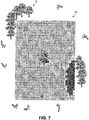
- FIGS. 4-7 shown are schematic diagrams each conceptually depicting a hybrid diagram comprising an example environment and the manner in which certain embodiments of a path planning system logically map the environment to assess the positional accuracy of areas or regions of the mapped area over a projected time as the satellite constellation changes (as projected based on satellite data corresponding to the orbits of the satellites, such as almanac data).
- an example environment 34 is shown with plural obstructions 36 and 38 situated proximal to the border of a field 40, and an in-field obstruction 42 located within the field 40.
- the obstructions 36, 38, and 42 are trees, though not limited to these types of obstructions and/or quantity or arrangement of obstructions.
- areas or regions A, B, C (shown for simplicity and for illustrative representation as circular, though as will be described below, may practically be more polygonal and irregular in shape), which indicate areas of compromised positional accuracies due to the occlusion of line of sight satellite signal reception as determined based on the information recorded and mapped by the path planning system, as described previously.
- the environment of 34 of FIG. 4 is shown as a diagram 44 that visually represents the obstructions 36, 38, and 42 located in or proximal to the field 40 and a first satellite geometry using satellites 46 (e.g., seven (7) shown, though other quantities may be used in some embodiments) at time equals T, where T is an instance of time where accuracy throughout the field 40 is determined. That is, the path planning system calculates the potential accuracy throughout the field 40 at various time projections and projected satellite geometries at those time projections.
- the distinction in anticipated accuracies is visually represented in FIG. 4 (and FIGS. 5-7 ) with differences in shading revealing three different areas of accuracy.
- areas 48 (e.g., 48A, 48B, and 48C), represented by the darkest shading, comprise an accuracy or represent a range of accuracies that are the lowest accuracy of the three different areas.
- Areas 50 represented with a shade that falls between the lightest and darkest areas, comprise an area of best accuracy or range of accuracies.
- Areas 52 (e.g., 52A, 52B, and 52C), represented with the lightest shading, comprise a transition area of an accuracy or range of accuracies that fall between the best and worst accuracy areas. Note that, although these area distinctions are quantified by absolute accuracies (e.g., single or range of accuracies), in some embodiments, a relative accuracy may be used.
- the areas 48 reveal the worst anticipated accuracies due to occlusions in satellite signal reception from the obstructions 36, 38, and 42 at a given time.
- the transition areas 52 provide a buffer between the best accuracy areas 50 and the least accuracy areas 48, though in some embodiments, fewer (e.g., no transitions) or more defined transition areas may be determined.
- the accuracies may be determined based on the obstruction map and dilution of precision (DOP) calculations, though other or additional measures of accuracy may be used in some embodiments.
- DOP dilution of precision
- FIG. 6 shown is a similar diagram 54 (i.e., similar to FIG. 4 ) but at projected time equals T+1 based on a subsequent satellite geometry.
- the nature (e.g., angle of) of occlusion of the line of sight satellite signals received by a GNSS receiver of (or associated with) a machine changes.
- the areas of least accuracy due to the obstructions 36, 38, and 42 in or proximal to the field 40 are areas 56 (e.g., 56A and 56B).
- the area 56A is smaller than the area 48A based on the satellite geometry expected at time T+1.
- FIG. 7 shown is a diagram 58 with yet another satellite geometry at projected time equals T+2.
- Other changes in the accuracies are also calculated to occur for other regions of the field 40, as projected over time equals T+2, as similarly described for FIGS. 5-6 , the discussion of which is omitted here for brevity.
- visual representations of all or part of the information provided in diagrams 44 ( FIG. 5 ), 54 ( FIG. 6 ), and 58 ( FIG. 7 ), among other information, may be provided to an operator or other personnel at a computing device (e.g., within the machine 12, FIG. 1 ) or a computing device external to the machine 12.
- an embodiment of the path planning system may assess when and how to traverse certain regions of the field according to previously used waylines. Attention is directed to FIG. 8A , which is a schematic diagram 60 that illustrates previously used waylines for the environment of FIG. 4 .
- An embodiment of the path planning system identifies waylines associated with regions A, B, and C that are worked at time equals T, T+1, and T+2, respectively, and assesses the accuracies. For instance, based on the anticipated accuracies determined by the path planning system (e.g., FIGS.
- FIG. 8B is a schematic diagram 62 that illustrates a union of anticipated accuracies based on traversal according to the waylines shown in FIG. 8A .
- areas of least accuracy 64 e.g., 64A, 64B, and 64C
- the path planning system may determine the assessments corresponding to FIG. 8A or the union of accuracies shown in FIG. 8B transparently (e.g., as part of the wayline determination process), or in some embodiments, present recommendations and/or options to an operator or other personnel (e.g., enabling operator intervention).
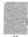
- FIG. 9A is a schematic diagram 66 that illustrates waylines determined by an embodiment of an example path planning system for the environment of FIG. 4 based on the maps of FIGS. 5-7 .
- the diagram 66 reveals that the path planning system has determined that a more optimized approach to traversing the field at improved accuracies is to traverse region C at time equals T, region B at time equals T+1, and region A at time equals T+2.
- accuracy is improved, as shown by the union of accuracies in FIG. 9B using this approach.
- the areas of least accuracy 70 e.g., 70A and 70B
- FIG. 10 is a schematic diagram 72 that illustrates waylines determined by an embodiment of an example path planning system that re-order previously used paths corresponding to waylines based on accuracy maps.
- the sequence of wayline path traversal is in the order of path 74 at time equals T, path 76 at time equals T+1, then advancing the machine to path 78 at T+3 (skipping the paths located between path 76 and path 78 for now), traversing path 80 at time equals T+4, and so on.
- the standard, sequential and progressive advancement of the machine across a field according to previous waylines is replaced with updated waylines that tailor or modify the sequence or order of path traversal, which reduces or eliminates positional inaccuracies that are based on satellite signal occlusions.
- the path planning system uses the satellite data recorded from previous passes of a field to map the obstructions in, of, or around the field. As the machine enters the field, the operator may load the waylines for the field. The path planning system calculates (for the entire field, though calculations may be done progressively at interrupted blocks of times based on the area or amount of time traveled for defined segments of the entire field in some embodiments) the potential accuracy at each point and projects these determined accuracies through time as the satellite geometries change. The path planning system then recommends an order in which the machine should traverse the paths to ensure that each region has the best accuracy.
- the path planning system updates the waylines according to the time and constellations that are projected from the restarting time.
- the path planning system may define new waylines based on the anticipated accuracy determinations.
- FIG. 11 shown is a schematic diagram 82 that illustrates new waylines of different wayline types or shapes as determined by an embodiment of an example path planning system based on accuracy maps.
- the path planning system has assessed the accuracy in similar manner to that described above for determining a revised order of path traversal, and then defines new waylines arranged according to a contour type 84 and straight A-B lines 86. It should be appreciated by one having ordinary skill in the art that the arrangement shown in FIG. 11 is merely illustrative, and that other arrangements and/or types may be used.
- the path planning system recommends traversal of paths 88, 90, 92, and 94 at respective times T, T+1, T+2, and T+3 of the contour wayline type, and then advancing to path 96 for T+4, path 98 for T+6, and so on.
- the path planning system uses the satellite data recorded from previous passes of a field to map the obstructions in, of, or around the field.
- the path planning system calculates (for the entire field, though calculations may be done progressively at interrupted blocks of times based on the area or amount of time traveled for defined segments of the entire field in some embodiments) the potential accuracy at each point and projects these determined accuracies through time as the satellite geometries change (e.g., as the constellation changes).
- the path planning system then designs new waylines for the operator (e.g., selecting type, such as straight, contour, and laying out their position and orientation) that optimizes position accuracy.
- the path planning system may further recommend an order in which the machine should traverse the paths to ensure that each region has the best accuracy.
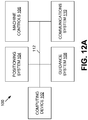
- FIG. 12A illustrates an embodiment of an example path planning system 100.
- the path planning system 100 may reside entirely in the machine (e.g., machine 12, FIG. 1 ), or in some embodiments, functionality of the path planning system 100 may be distributed among plural devices or systems (e.g., within the machine and external to the machine). In some embodiments, functionality of the path planning system 100 may reside in a single device, such as a local or remote computing device.
- the path planning system 100 comprises one or more computing devices, such as computing device 102.
- the computing device 102 may reside in the machine 12 and comprises an electronic control unit (ECU).
- the computing device 102 is coupled to a positioning system 104, machine controls 106, a guidance system 108, and a communications system 110, all coupled to each other via a network 112.
- a network 112. It should be appreciated by one having ordinary skill in the art, in the context of the present disclosure, that functionality for the various depicted components may be combined in a single device (e.g., single ECU), or further distributed among additional components locally or among disparate locations.
- the network 112 may be embodied as a controller area network (CAN), such as in conformance to ISO 11898, ISO 11783, etc.), though in some embodiments, other protocols and/or standards (e.g., RS 232) may be used.
- CAN controller area network
- the computing device 102 comprises a computer architecture, including a processor, memory, and input/output interfaces, including a user interface such as one or a combination of a display terminal or screen, keyboard and/or other devices, such as a mouse, stylus, microphone, joystick, among others user-interface components well-known to one having ordinary skill in the art.
- the computing device 102 enables an operator to centrally access the various functionality of the machine 12 ( FIG. 1 ), such as auto-steer functionality of the guidance system 108 and the GNSS receiver functionality of the positioning system 104.
- user interface functionality may be provided with each ECU and/or component.
- the positioning system 104 comprises a GNSS receiver, and is configured to access one or more constellations of satellites to receive satellite data and process the data to determine the coordinate position of the machine 12 ( FIG. 1 ) and/or coordinate position of the GNSS receiver and the azimuth and elevation information of the satellites.
- the satellite data may include clocking and/or phase information, and an almanac, as is known in the art.
- the positioning system 104 triangulates its position (and/or the position of the machine 12), enabling the determination of size and location of the obstructions in, of, and/or around a field.
- the machine controls 106 collectively comprise the various actuators, sensors, and/or subsystems residing on the machine 12 ( FIG. 1 ), including those used to control machine navigation (e.g., speed, direction (such as a steering system), etc.), implement (e.g., header or trailer) position, and/or control of internal processes, among others.
- machine navigation e.g., speed, direction (such as a steering system), etc.
- implement e.g., header or trailer
- the guidance system 108 comprises the various components that enable semi-autonomous or autonomous traversal of a field by the machine 12 ( FIG. 1 ), including gyroscopes, accelerometers, among other sensors.
- the guidance system 108 further comprises guidance software/firmware (e.g., in the computing device 102 or in the guidance system 108), and cooperates with the machine controls 106, and the positioning system 104 to provide, for instance, auto-steer functionality.
- the communications system 110 enables wireless (and/or wired) communication with other devices or systems, such as remote connection to external networks or devices.
- the communications system 110 comprises a radio frequency (RF) modem and cellular modem to enable wireless fidelity (Wi-Fi) and cellular communications, respectively.
- RF radio frequency
- Wi-Fi wireless fidelity
- the information recorded by the path planning system 100 such as a map of obstructions or accuracy maps, may be communicated via the cellular modem of the communications system 110 to a remote server or other computing device for further processing, such as for the determination of waylines (whether according to a re-ordering of path traversal sequence or design of new waylines).
- the computing device 102 is configured to receive and process information from the positioning system 104, machine controls 106, guidance system 108, and communications system 110. For instance, the computing device 102 may receive input from a user interface, such as to enable intervention of machine operation by the operator, to provide feedback of a change in speed or direction and/or or an impending change or need or recommendation for change or wayline path ordering or selection of wayline types, or to commence and ultimately engage auto-steer. In some embodiments, the computing device 102 may present the map of obstructions, as well as maps of anticipated accuracies. Such maps may include an indication of regions where occlusion of satellite signals is anticipated, as well as recommended waylines (e.g., ordering and/or types).
- the computing device 102 may receive input from the machine controls 106 (e.g., such as to enable feedback as to the position or status of certain devices, such as a header height and/or width, and/or speed, direction of the machine 12 of FIG. 1 , etc.).
- the computing device 102 may further be configured with software and/or firmware that are used in conjunction with the various components, such as guidance software to be used with the guidance system 108, machine controls 106, and the positioning system 104, and path planning software to be used in conjunction with the positioning system 104 and/or the guidance system 108.
- the computing device 102 is also configured to cause the access of data from a data structure via the communications system 110 to forward satellite data (e.g., an almanac) and/or other information (e.g., coordinate position, azimuth, elevation, etc. that may be computed based on the satellite data) to a remote terminal and to enable computation (e.g., offline or real-time) of obstruction and/or accuracy maps and ultimately recommended waylines.
- satellite data e.g., an almanac
- other information e.g., coordinate position, azimuth, elevation, etc. that may be computed based on the satellite data
- computation e.g., offline or real-time
- one or more of the functionality of the path planning system 100 may be performed remotely to benefit from increased processing power and/or remote control or management of machine operations.
- one or more of the functionality of the computing device 102 may be integrated in one of the other components, such as in the positioning system 104 or the guidance system 108 (or a combination of components).
- FIG. 12B further illustrates an example embodiment of the computing device 102.
- the computing device 102 is depicted in this example as a computer system, but may be embodied as a programmable logic controller (PLC), FPGA, ASIC, among other devices.
- PLC programmable logic controller
- FPGA field-programmable gate array
- ASIC application-specific integrated circuit
- the computing device 102 comprises one or more processing units, such as processing unit 114, input/output (I/O) interface(s) 116, user interface 118, and memory 120, all coupled to one or more data busses, such as data bus 122.
- processing unit 114 input/output
- I/O interface(s) 116 input/output
- user interface 118 may be a separate component accessed over the network 112 via the I/O interfaces 116.
- the memory 120 may include any one or a combination of volatile memory elements (e.g., random-access memory RAM, such as DRAM, and SRAM, etc.) and nonvolatile memory elements (e.g., ROM, hard drive, tape, CDROM, etc.).
- volatile memory elements e.g., random-access memory RAM, such as DRAM, and SRAM, etc.
- nonvolatile memory elements e.g., ROM, hard drive, tape, CDROM, etc.
- the memory 120 may store a native operating system, one or more native applications, emulation systems, or emulated applications for any of a variety of operating systems and/or emulated hardware platforms, emulated operating systems, etc.
- the memory 120 may store one or more field maps that were recorded from a prior traversal of a given field, waylines (e.g., previously used), accuracy maps, satellite data, etc.
- the memory 120 comprises an operating system 124, machine guidance software 126, path planning software 128, which may include (though in some embodiments, may be segregated modules) obstruction mapping software 130, accuracy anticipation software 132, and maps 134 (e.g., obstruction maps, accuracy maps, etc.).
- the path planning software 128 may be part of the guidance software 126, or a separate module that feeds data to the guidance software.
- the path planning software 128 uses information from the maps 134 to determine waylines.
- the obstruction mapping software 130 generates obstruction maps (e.g., three-dimensional obstruction maps) of obstructions for a field based on the satellite data and well-known triangulation computations (e.g., based on cutoff angles).
- the GNSS receiver of the positioning system 104 receives satellite data and computes the (machine) coordinate position and the azimuth and elevation of the satellites.
- the path planning software 128 uses the maps 134 (e.g., obstruction maps) or, in some embodiments, forwards to the accuracy anticipation software 132.
- the accuracy anticipation software 132 receives almanac data and determines the anticipated accuracy in positioning across the field (e.g., at plural projected times based on plural satellite geometries) based on the obstruction maps and stores the accuracy maps in maps 134 or, in some embodiments, forwards to the wayline generation component of the machine guidance software 126.
- the accuracy maps may be used at a remote computing device (e.g., communicated via telemetry, transferred via a portable memory component, etc.) for remote wayline determinations that are based on the accuracy maps.
- the accuracy anticipation software 132 computes the accuracy throughout the field using geometric and/or horizontal DOP calculations, though some embodiments may use other measures to assess the anticipated positional accuracy.
- the wayline generation component of the machine guidance software 126 uses the accuracy maps to determine (e.g., without operator intervention) waylines to be traversed (e.g., new design, or re-ordered paths).
- the machine guidance software 126 may present to an operator (e.g., within the machine 12 or external to the machine) recommended waylines that the operator chooses from, thus enabling operator intervention.
- the maps 134 may comprise one or more data structures corresponding to the information in FIGS. 1-7 , such as obstruction maps and accuracy maps. It should be appreciated that in some embodiments, additional or fewer software modules (e.g., combined functionality) may be employed in the memory 120 or additional memory, or the arrangement of modules may be different.
- a separate storage device may be coupled to the data bus 122 (or network 112, FIG. 12A ), such as a persistent memory (e.g., optical, magnetic, and/or semiconductor memory and associated drives).
- the machine guidance software 126 further enables autonomous or semi-autonomous travel by the machine 12 ( FIG. 1 ) based on the waylines and further based on the continually updated positioning data provided by the positioning system 104 (e.g., FIG. 12A , accessed via I/O interfaces 116).
- Execution of the application software modules 126-132 may be implemented by the processing unit 114 under the management and/or control of the operating system 124.
- the operating system 124 may be omitted and a more rudimentary manner of control implemented.
- the processing unit 114 may be embodied as a custom-made or commercially available processor, a central processing unit (CPU) or an auxiliary processor among several processors, a semiconductor based microprocessor (in the form of a microchip), a macroprocessor, one or more application specific integrated circuits (ASICs), a plurality of suitably configured digital logic gates, and/or other well-known electrical configurations comprising discrete elements both individually and in various combinations to coordinate the overall operation of the computing device 102.
- CPU central processing unit
- ASICs application specific integrated circuits
- the I/O interfaces 116 provide one or more interfaces to the network 112 ( FIG. 12A ) and other networks.
- the I/O interfaces 116 may comprise any number of interfaces for the input and output of signals (e.g., analog or digital data) for conveyance over the network 112.
- the input may comprise input by an operator (local or remote) through the user interface 118 (e.g., a keyboard, joystick, steering wheel, touch-display, or mouse or other input device (or audible input in some embodiments)), and input from signals carrying information from one or more of the components of the path planning system 100 ( FIG. 12A ).
- a computer-readable medium may comprise an electronic, magnetic, optical, or other physical device or apparatus that may contain or store a computer program (e.g., executable code or instructions) for use by or in connection with a computer-related system or method.
- the software may be embedded in a variety of computer-readable mediums for use by, or in connection with, an instruction execution system, apparatus, or device, such as a computer-based system, processor-containing system, or other system that can fetch the instructions from the instruction execution system, apparatus, or device and execute the instructions.
- an instruction execution system, apparatus, or device such as a computer-based system, processor-containing system, or other system that can fetch the instructions from the instruction execution system, apparatus, or device and execute the instructions.
- computing device 102 When certain embodiment of the computing device 102 are implemented at least in part as hardware, such functionality may be implemented with any or a combination of the following technologies, which are all well-known in the art: a discrete logic circuit(s) having logic gates for implementing logic functions upon data signals, an application specific integrated circuit (ASIC) having appropriate combinational logic gates, a programmable gate array(s) (PGA), a field programmable gate array (FPGA), etc.
- ASIC application specific integrated circuit
- PGA programmable gate array
- FPGA field programmable gate array
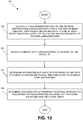
- one embodiment of a path planning method comprises receiving a three dimensional map of one or more obstructions associated with a field, the one or more obstructions presenting an obstacle to line of sight reception from a satellite to a global navigation satellite systems (GNSS) receiver (138); receiving almanac data corresponding to an orbit of the satellite (140); determining anticipated accuracy of positioning in the field at plural locations and plural times based on the almanac data and the map (142); and determining waylines for autonomous traversal through the field based on the anticipated accuracy at the plural locations and the plural times (144).
- GNSS global navigation satellite systems
Landscapes
- Engineering & Computer Science (AREA)
- Radar, Positioning & Navigation (AREA)
- Remote Sensing (AREA)
- Physics & Mathematics (AREA)
- General Physics & Mathematics (AREA)
- Automation & Control Theory (AREA)
- Computer Networks & Wireless Communication (AREA)
- Aviation & Aerospace Engineering (AREA)
- Life Sciences & Earth Sciences (AREA)
- Mechanical Engineering (AREA)
- Soil Sciences (AREA)
- Environmental Sciences (AREA)
- Position Fixing By Use Of Radio Waves (AREA)
- Navigation (AREA)
Claims (18)
- Verfahren, mit:Empfangen (138) einer dreidimensionalen Karte eines oder mehrerer einem Feld (14) zugehöriger Hindernisse (18), wobei das eine oder die mehreren Hindernisse ein Hemmnis für einen Sichtlinien-Empfang von einem Satelliten (16) an einen Empfänger für globale Navigationssatellitensysteme ("global navigation satellite systems"; GNSS) ist oder sind;Empfangen (140) von Almanach-Daten, die einem Orbit des Satelliten (18) entsprechen;Bestimmen (142) einer erwarteten Genauigkeit einer GNSS-Positionsbestimmung in dem Feld an mehreren Orten und zu mehreren Zeiten basierend auf den Almanach-Daten und der Karte; undBestimmen (144) von Weglinien für ein autonomes Durchfahren des Felds basierend auf der erwarteten Genauigkeit an den mehreren Orten und zu den mehreren Zeiten; dadurch gekennzeichnet, dassdas Bestimmen (144) der Weglinien zum Durchfahren des Felds ein Neuordnen einer Abfolge eines Durchfahrens von Pfaden aufweist, die zuvor zum Durchfahren des Felds benutzten Weglinien zugehörig sind.
- Verfahren nach Anspruch 1, wobei das Bestimmen (142) der erwarteten Genauigkeit ein Berechnen einer Präzisionsabschwächung ("dilution of precision"; DOP) für über das Feld (14) verteilte Punkte umfasst.
- Verfahren nach Anspruch 1, wobei das Bestimmen (144) der Weglinien zum Durchfahren des Felds weiterhin das Generieren neuer Weglinien aufweist.
- Verfahren nach Anspruch 3, wobei das Generieren neuer Weglinien das Benutzen mehrerer Weglinien-Typen aufweist.
- Verfahren nach Anspruch 1, wobei das Durchfahren der Weglinien zum Verbessern einer Gesamt-Positionierungsgenauigkeit geplant ist.
- Verfahren nach Anspruch 1, wobei das Bestimmen (142) der erwarteten Genauigkeit der GNSS-Positionsbestimmung im Feld (14) an den mehreren Orten und zu den mehreren Zeiten ein Bestimmen der erwarteten Genauigkeit zu definierten projizierten Zeitschritten zum Durchfahren des gesamten Felds aufweist.
- Verfahren nach Anspruch 1, weiterhin mit dem Bereitstellen der Weglinien zur Benutzung durch ein Führungssystem.
- Verfahren nach Anspruch 1, weiterhin mit dem Neubestimmen der Weglinien als Reaktion auf eine Unterbrechung des Durchfahrens des Felds, die während des Durchfahrens nach den bestimmten Weglinien auftritt.
- Verfahren nach Anspruch 1, wobei das eine oder die mehreren Hindernisse (18) eines oder eine Kombination von In-Feld-Hindernissen, Hindernissen entlang einer Grenze oder Geländehindernissen aufweist oder aufweisen.
- System (100), mit:einer Maschine (12) mit einem Führungssystem (108) und einem Empfänger für ein globales Navigationssatellitensystem ("global navigation satellite systems"; GNSS), wobei der Empfänger für das GNSS dazu eingerichtet ist, Almanach-Daten zu empfangen, die einem Orbit eines Satelliten (16) entsprechen;einer Recheneinrichtung (102), die dazu eingerichtet ist:eine dreidimensionale Karte von einem oder mehreren einem Feld (14) zugehörigen Hindernissen (18) zu empfangen, wobei das eine oder die mehreren Hindernisse ein Hemmnis für einen Sichtlinien-Empfang von dem Satelliten (16) an den GNSS-Empfänger darstellt oder darstellen;eine erwartete Genauigkeit einer GNSS-Positionsbestimmung der Maschine (12) in dem Feld (14) an mehreren Orten und zu mehreren Zeiten basierend auf den Almanach-Daten und der Karte zu bestimmen; undWeglinien für ein autonomes Durchfahren des Felds (14) basierend auf der erwarteten Genauigkeit an den mehreren Orten und zu den mehreren Zeiten zu bestimmen; dadurch gekennzeichnet, dassdie Recheneinrichtung (102) dazu eingerichtet ist, die Weglinien durch Neuordnen einer Abfolge eines Durchfahrens von Pfaden zu bestimmen, die zuvor zum Durchfahren des Felds (14) benutzten Weglinien zugehörig sind.
- System nach Anspruch 10, wobei die Recheneinrichtung (102) dazu eingerichtet ist, die erwartete Genauigkeit durch Berechnen einer Präzisionsabschwächung ("dilution of precision"; DOP) für über das Feld verteilte Punkte zu bestimmen.
- System nach Anspruch 10, wobei die Recheneinrichtung (102) weiterhin dazu eingerichtet ist, die Weglinien durch das Generieren neuer Weglinien zu bestimmen.
- System nach Anspruch 12, wobei die Recheneinrichtung (102) dazu eingerichtet ist, neue Weglinien unter Benutzung mehrerer Weglinien-Typen zu generieren.
- System nach Anspruch 10, wobei die Recheneinrichtung (102) dazu eingerichtet ist, Weglinien zu bestimmen, die eine Gesamt-GNSS-Positionsbestimmungsgenauigkeit verbessern.
- System nach Anspruch 10, wobei die Recheneinrichtung (102) dazu eingerichtet ist, die erwartete Genauigkeit der GNSS-Positionsbestimmung in dem Feld (14) an den mehreren Orten und zu den mehreren Zeiten zu bestimmen, indem sie die erwartete Genauigkeit an definierten projizierten Zeitschritten zum Durchfahren des gesamten Felds bestimmt.
- System nach Anspruch 10, wobei die Recheneinrichtung (102) dazu eingerichtet ist, die Weglinien zu benutzen, um die Maschine (12) autonom zu führen.
- System nach Anspruch 10, wobei die Recheneinrichtung (102) dazu eingerichtet ist, Weglinien als Reaktion auf eine Unterbrechung des Durchfahrens des Feldes neu zu bestimmen, die während des Durchfahrens durch die Maschine (12) nach den bestimmten Weglinien auftritt.
- System nach Anspruch 10, wobei die Maschine (12) weiterhin die Recheneinrichtung (102) aufweist.
Applications Claiming Priority (1)
| Application Number | Priority Date | Filing Date | Title |
|---|---|---|---|
| US201562127938P | 2015-03-04 | 2015-03-04 |
Publications (2)
| Publication Number | Publication Date |
|---|---|
| EP3064964A1 EP3064964A1 (de) | 2016-09-07 |
| EP3064964B1 true EP3064964B1 (de) | 2018-08-29 |
Family
ID=55521455
Family Applications (1)
| Application Number | Title | Priority Date | Filing Date |
|---|---|---|---|
| EP16157132.8A Active EP3064964B1 (de) | 2015-03-04 | 2016-02-24 | Pfadplanung auf grundlage von blockadekartierung |
Country Status (2)
| Country | Link |
|---|---|
| US (1) | US10139234B2 (de) |
| EP (1) | EP3064964B1 (de) |
Families Citing this family (33)
| Publication number | Priority date | Publication date | Assignee | Title |
|---|---|---|---|---|
| US9885789B2 (en) | 2013-03-14 | 2018-02-06 | Google Llc | Accounting for atmospheric and terrestrial obstacles in geographic positioning |
| US10742309B2 (en) * | 2017-06-14 | 2020-08-11 | Higher Ground Llc | Spatial router with dynamic queues |
| CN108733065B (zh) * | 2017-09-29 | 2021-06-04 | 北京猎户星空科技有限公司 | 一种机器人的避障方法、装置及机器人 |
| CN108413963B (zh) * | 2018-02-12 | 2021-06-08 | 淮安信息职业技术学院 | 基于自学习蚁群算法的条形机器人路径规划方法 |
| US11087487B2 (en) | 2018-10-25 | 2021-08-10 | Northrop Grumman Systems Corporation | Obscuration map generation |
| US10708718B1 (en) * | 2019-02-28 | 2020-07-07 | At&T Intellectual Property I, L.P. | Space characterization using electromagnetic fields |
| JP6961636B2 (ja) * | 2019-03-01 | 2021-11-05 | 日立建機株式会社 | 作業機械 |
| US11573329B2 (en) * | 2019-03-28 | 2023-02-07 | Lyft, Inc. | Modeling effects of structures on global-positioning system localization |
| CN110095789B (zh) * | 2019-04-22 | 2021-07-06 | 惠州Tcl移动通信有限公司 | 一种终端定位方法、装置及存储介质 |
| EP4036324B1 (de) * | 2019-09-26 | 2025-09-03 | Hitachi Construction Machinery Co., Ltd. | Arbeitsmaschine |
| CN112857368B (zh) * | 2019-11-12 | 2024-04-09 | 苏州宝时得电动工具有限公司 | 一种割草机导航方法、装置和割草机 |
| US11748824B2 (en) | 2020-01-31 | 2023-09-05 | Deere & Company | Systems and methods for site traversability sensing |
| US12016257B2 (en) | 2020-02-19 | 2024-06-25 | Sabanto, Inc. | Methods for detecting and clearing debris from planter gauge wheels, closing wheels and seed tubes |
| JP7419119B2 (ja) * | 2020-03-16 | 2024-01-22 | 日立建機株式会社 | 作業機械 |
| CN111487976B (zh) * | 2020-05-03 | 2022-11-18 | 哈尔滨工程大学 | 一种倒车轨迹跟踪方法 |
| US11287531B2 (en) * | 2020-07-14 | 2022-03-29 | Spirent Communications, Plc | Architecture for providing forecasts of GNSS obscuration and multipath |
| US11536855B2 (en) | 2020-07-14 | 2022-12-27 | Spirent Communications Plc | Path planning using forecasts of obscuration and multipath |
| US12292515B2 (en) | 2020-07-14 | 2025-05-06 | Spirent Communications Plc | Generating and distributing GNSS risk analysis data for facilitating safe routing of autonomous drones |
| US12265159B2 (en) | 2020-07-14 | 2025-04-01 | Spirent Communications Plc | GNSS forecast impacting receiver startup |
| US11789161B2 (en) | 2020-07-14 | 2023-10-17 | Spirent Communications Plc | Accuracy of a GNSS receiver that has a non-directional antenna |
| US12298409B2 (en) | 2020-07-14 | 2025-05-13 | Spirent Communications Plc | GNSS forecast and background obscuration prediction |
| US12468045B1 (en) | 2020-07-14 | 2025-11-11 | Spirent Communications Plc | Utilizing GNSS risk analysis data for facilitating safe routing of autonomous drones |
| US12429599B2 (en) | 2020-07-14 | 2025-09-30 | Spirent Communications Plc | GNSS forecast and spoofing/jamming detection |
| US12282101B2 (en) | 2020-07-14 | 2025-04-22 | Spirent Communications Plc | GNSS forecast and line of sight detection |
| US12461083B2 (en) | 2020-08-03 | 2025-11-04 | Sabanto, Inc. | Methods for improved agricultural procedures |
| CN112297011B (zh) * | 2020-10-29 | 2023-07-21 | 久瓴(上海)智能科技有限公司 | 农林机器人避障方法、装置、计算机设备和存储介质 |
| CN116466696B (zh) * | 2022-01-11 | 2025-11-28 | 未岚大陆(北京)科技股份有限公司 | 路径规划方法、装置、自动园艺设备、及计算机程序产品 |
| CN114630271B (zh) * | 2022-03-15 | 2025-12-23 | 北京小米移动软件有限公司 | 定位方法、装置、电子设备和存储介质 |
| JP7819546B2 (ja) * | 2022-03-22 | 2026-02-25 | カシオ計算機株式会社 | 情報処理装置、情報処理方法及びプログラム |
| EP4564115A4 (de) * | 2022-07-27 | 2025-06-04 | Greenworks (Jiangsu) Co., Ltd. | Gartenwerkzeug, steuerungsverfahren dafür und system |
| US12517259B2 (en) | 2022-09-16 | 2026-01-06 | Spirent Communications Plc | Utilizing low earth orbit (LEO) satellite data for obscuration and multipath risk analysis |
| US12517264B2 (en) | 2022-09-16 | 2026-01-06 | Spirent Communications Plc | Architecture for providing forecasts of low earth orbit (LEO) satellite obscuration and multipath |
| WO2024135651A1 (ja) * | 2022-12-22 | 2024-06-27 | 株式会社クボタ | 計画作成装置、計画作成方法、及びコンピュータプログラム |
Family Cites Families (4)
| Publication number | Priority date | Publication date | Assignee | Title |
|---|---|---|---|---|
| JP3598601B2 (ja) * | 1995-08-23 | 2004-12-08 | 神鋼電機株式会社 | 無人車の運行管理システム |
| JP2007240322A (ja) * | 2006-03-08 | 2007-09-20 | Sony Corp | ナビゲーション装置及びナビゲーション表示方法 |
| JP5045301B2 (ja) * | 2007-08-09 | 2012-10-10 | トヨタ自動車株式会社 | 車両の走行制御装置 |
| US8645060B2 (en) * | 2010-09-07 | 2014-02-04 | Qualcomm Incorporated | Positioning network availability and reliability based routing |
-
2016
- 2016-02-24 EP EP16157132.8A patent/EP3064964B1/de active Active
- 2016-02-25 US US15/053,320 patent/US10139234B2/en active Active
Also Published As
| Publication number | Publication date |
|---|---|
| EP3064964A1 (de) | 2016-09-07 |
| US10139234B2 (en) | 2018-11-27 |
| US20160258759A1 (en) | 2016-09-08 |
Similar Documents
| Publication | Publication Date | Title |
|---|---|---|
| EP3064964B1 (de) | Pfadplanung auf grundlage von blockadekartierung | |
| US11269346B2 (en) | 3-d image system for vehicle control | |
| EP2656109B1 (de) | Verfahren, vorrichtungen, und verwendungen zur kalkulation einer position unter verwendung eines globalen navigationssatellitensystems | |
| US9602974B2 (en) | Dead reconing system based on locally measured movement | |
| EP3206104B1 (de) | Verfahren zur verwendung von positions-/stellungsinformationen zur verbesserung eines fahrzeugführungssystems | |
| EP3059611A1 (de) | Gnss-basierte blockadekartierung | |
| EP4089367B1 (de) | Hybride himmel- und bodennavigation für maschinen, die satellitenortung einsetzen | |
| US8818722B2 (en) | Rapid lidar image correlation for ground navigation | |
| EP3696576B1 (de) | Robotisches fahrzeug zur bodenbearbeitung | |
| CN115856973B (zh) | Gnss解算方法、装置、定位系统、电子设备及存储介质 | |
| WO2014176062A1 (en) | Position identification system with multiple cross-checks | |
| US10024977B1 (en) | Low speed heading measurement | |
| EP1738138B1 (de) | System und verfahren zur erzeugung genauer topographischer karten mit dgps | |
| CN108845339A (zh) | 一种gnss定位方法及gnss定位设备 | |
| CN112230256A (zh) | 自主机器人及其定位校准方法、装置和存储介质 | |
| CN116500658A (zh) | 自移动设备的位置修正方法、装置、自移动设备及介质 | |
| CN116295435B (zh) | 自移动设备的路径规划方法、装置、设备及存储介质 | |
| CN116295357B (zh) | 地图更新方法、装置、自移动设备及计算机可读存储介质 | |
| EP3508884B1 (de) | Intelligenter satellitenausschluss zur mehrpfadabschwächung auf basis einer sichtlinie | |
| CN111142133B (zh) | 基于多个连续运行参考站的后处理定位方法和系统 | |
| CN112578423A (zh) | 整周模糊度确定方法、装置及设备 | |
| US12468048B2 (en) | Post-processing of global navigation satellite system (GNSS) data | |
| Obregón et al. | Adaptive Localization Configuration for Autonomous Scouting Robot in a Harsh Environment | |
| CN115443792B (zh) | 割草机的建图方法、系统及可读存储介质 | |
| CN117848333A (zh) | 自移动设备的移动轨迹修正方法、装置、自移动设备 |
Legal Events
| Date | Code | Title | Description |
|---|---|---|---|
| PUAI | Public reference made under article 153(3) epc to a published international application that has entered the european phase |
Free format text: ORIGINAL CODE: 0009012 |
|
| AK | Designated contracting states |
Kind code of ref document: A1 Designated state(s): AL AT BE BG CH CY CZ DE DK EE ES FI FR GB GR HR HU IE IS IT LI LT LU LV MC MK MT NL NO PL PT RO RS SE SI SK SM TR |
|
| AX | Request for extension of the european patent |
Extension state: BA ME |
|
| STAA | Information on the status of an ep patent application or granted ep patent |
Free format text: STATUS: REQUEST FOR EXAMINATION WAS MADE |
|
| 17P | Request for examination filed |
Effective date: 20170307 |
|
| RBV | Designated contracting states (corrected) |
Designated state(s): AL AT BE BG CH CY CZ DE DK EE ES FI FR GB GR HR HU IE IS IT LI LT LU LV MC MK MT NL NO PL PT RO RS SE SI SK SM TR |
|
| GRAP | Despatch of communication of intention to grant a patent |
Free format text: ORIGINAL CODE: EPIDOSNIGR1 |
|
| STAA | Information on the status of an ep patent application or granted ep patent |
Free format text: STATUS: GRANT OF PATENT IS INTENDED |
|
| INTG | Intention to grant announced |
Effective date: 20180403 |
|
| RAP1 | Party data changed (applicant data changed or rights of an application transferred) |
Owner name: AGCO CORPORATION |
|
| GRAS | Grant fee paid |
Free format text: ORIGINAL CODE: EPIDOSNIGR3 |
|
| GRAA | (expected) grant |
Free format text: ORIGINAL CODE: 0009210 |
|
| STAA | Information on the status of an ep patent application or granted ep patent |
Free format text: STATUS: THE PATENT HAS BEEN GRANTED |
|
| AK | Designated contracting states |
Kind code of ref document: B1 Designated state(s): AL AT BE BG CH CY CZ DE DK EE ES FI FR GB GR HR HU IE IS IT LI LT LU LV MC MK MT NL NO PL PT RO RS SE SI SK SM TR |
|
| REG | Reference to a national code |
Ref country code: GB Ref legal event code: FG4D |
|
| REG | Reference to a national code |
Ref country code: CH Ref legal event code: EP |
|
| REG | Reference to a national code |
Ref country code: AT Ref legal event code: REF Ref document number: 1035773 Country of ref document: AT Kind code of ref document: T Effective date: 20180915 |
|
| REG | Reference to a national code |
Ref country code: IE Ref legal event code: FG4D |
|
| REG | Reference to a national code |
Ref country code: DE Ref legal event code: R096 Ref document number: 602016005056 Country of ref document: DE |
|
| REG | Reference to a national code |
Ref country code: NL Ref legal event code: MP Effective date: 20180829 |
|
| REG | Reference to a national code |
Ref country code: LT Ref legal event code: MG4D |
|
| PG25 | Lapsed in a contracting state [announced via postgrant information from national office to epo] |
Ref country code: NO Free format text: LAPSE BECAUSE OF FAILURE TO SUBMIT A TRANSLATION OF THE DESCRIPTION OR TO PAY THE FEE WITHIN THE PRESCRIBED TIME-LIMIT Effective date: 20181129 Ref country code: RS Free format text: LAPSE BECAUSE OF FAILURE TO SUBMIT A TRANSLATION OF THE DESCRIPTION OR TO PAY THE FEE WITHIN THE PRESCRIBED TIME-LIMIT Effective date: 20180829 Ref country code: SE Free format text: LAPSE BECAUSE OF FAILURE TO SUBMIT A TRANSLATION OF THE DESCRIPTION OR TO PAY THE FEE WITHIN THE PRESCRIBED TIME-LIMIT Effective date: 20180829 Ref country code: FI Free format text: LAPSE BECAUSE OF FAILURE TO SUBMIT A TRANSLATION OF THE DESCRIPTION OR TO PAY THE FEE WITHIN THE PRESCRIBED TIME-LIMIT Effective date: 20180829 Ref country code: GR Free format text: LAPSE BECAUSE OF FAILURE TO SUBMIT A TRANSLATION OF THE DESCRIPTION OR TO PAY THE FEE WITHIN THE PRESCRIBED TIME-LIMIT Effective date: 20181130 Ref country code: LT Free format text: LAPSE BECAUSE OF FAILURE TO SUBMIT A TRANSLATION OF THE DESCRIPTION OR TO PAY THE FEE WITHIN THE PRESCRIBED TIME-LIMIT Effective date: 20180829 Ref country code: IS Free format text: LAPSE BECAUSE OF FAILURE TO SUBMIT A TRANSLATION OF THE DESCRIPTION OR TO PAY THE FEE WITHIN THE PRESCRIBED TIME-LIMIT Effective date: 20181229 Ref country code: NL Free format text: LAPSE BECAUSE OF FAILURE TO SUBMIT A TRANSLATION OF THE DESCRIPTION OR TO PAY THE FEE WITHIN THE PRESCRIBED TIME-LIMIT Effective date: 20180829 Ref country code: BG Free format text: LAPSE BECAUSE OF FAILURE TO SUBMIT A TRANSLATION OF THE DESCRIPTION OR TO PAY THE FEE WITHIN THE PRESCRIBED TIME-LIMIT Effective date: 20181129 |
|
| REG | Reference to a national code |
Ref country code: AT Ref legal event code: MK05 Ref document number: 1035773 Country of ref document: AT Kind code of ref document: T Effective date: 20180829 |
|
| PG25 | Lapsed in a contracting state [announced via postgrant information from national office to epo] |
Ref country code: LV Free format text: LAPSE BECAUSE OF FAILURE TO SUBMIT A TRANSLATION OF THE DESCRIPTION OR TO PAY THE FEE WITHIN THE PRESCRIBED TIME-LIMIT Effective date: 20180829 Ref country code: AL Free format text: LAPSE BECAUSE OF FAILURE TO SUBMIT A TRANSLATION OF THE DESCRIPTION OR TO PAY THE FEE WITHIN THE PRESCRIBED TIME-LIMIT Effective date: 20180829 Ref country code: HR Free format text: LAPSE BECAUSE OF FAILURE TO SUBMIT A TRANSLATION OF THE DESCRIPTION OR TO PAY THE FEE WITHIN THE PRESCRIBED TIME-LIMIT Effective date: 20180829 |
|
| PG25 | Lapsed in a contracting state [announced via postgrant information from national office to epo] |
Ref country code: EE Free format text: LAPSE BECAUSE OF FAILURE TO SUBMIT A TRANSLATION OF THE DESCRIPTION OR TO PAY THE FEE WITHIN THE PRESCRIBED TIME-LIMIT Effective date: 20180829 Ref country code: PL Free format text: LAPSE BECAUSE OF FAILURE TO SUBMIT A TRANSLATION OF THE DESCRIPTION OR TO PAY THE FEE WITHIN THE PRESCRIBED TIME-LIMIT Effective date: 20180829 Ref country code: AT Free format text: LAPSE BECAUSE OF FAILURE TO SUBMIT A TRANSLATION OF THE DESCRIPTION OR TO PAY THE FEE WITHIN THE PRESCRIBED TIME-LIMIT Effective date: 20180829 Ref country code: RO Free format text: LAPSE BECAUSE OF FAILURE TO SUBMIT A TRANSLATION OF THE DESCRIPTION OR TO PAY THE FEE WITHIN THE PRESCRIBED TIME-LIMIT Effective date: 20180829 Ref country code: CZ Free format text: LAPSE BECAUSE OF FAILURE TO SUBMIT A TRANSLATION OF THE DESCRIPTION OR TO PAY THE FEE WITHIN THE PRESCRIBED TIME-LIMIT Effective date: 20180829 Ref country code: ES Free format text: LAPSE BECAUSE OF FAILURE TO SUBMIT A TRANSLATION OF THE DESCRIPTION OR TO PAY THE FEE WITHIN THE PRESCRIBED TIME-LIMIT Effective date: 20180829 |
|
| PG25 | Lapsed in a contracting state [announced via postgrant information from national office to epo] |
Ref country code: SK Free format text: LAPSE BECAUSE OF FAILURE TO SUBMIT A TRANSLATION OF THE DESCRIPTION OR TO PAY THE FEE WITHIN THE PRESCRIBED TIME-LIMIT Effective date: 20180829 Ref country code: DK Free format text: LAPSE BECAUSE OF FAILURE TO SUBMIT A TRANSLATION OF THE DESCRIPTION OR TO PAY THE FEE WITHIN THE PRESCRIBED TIME-LIMIT Effective date: 20180829 Ref country code: SM Free format text: LAPSE BECAUSE OF FAILURE TO SUBMIT A TRANSLATION OF THE DESCRIPTION OR TO PAY THE FEE WITHIN THE PRESCRIBED TIME-LIMIT Effective date: 20180829 |
|
| REG | Reference to a national code |
Ref country code: DE Ref legal event code: R097 Ref document number: 602016005056 Country of ref document: DE |
|
| PLBE | No opposition filed within time limit |
Free format text: ORIGINAL CODE: 0009261 |
|
| STAA | Information on the status of an ep patent application or granted ep patent |
Free format text: STATUS: NO OPPOSITION FILED WITHIN TIME LIMIT |
|
| 26N | No opposition filed |
Effective date: 20190531 |
|
| PG25 | Lapsed in a contracting state [announced via postgrant information from national office to epo] |
Ref country code: SI Free format text: LAPSE BECAUSE OF FAILURE TO SUBMIT A TRANSLATION OF THE DESCRIPTION OR TO PAY THE FEE WITHIN THE PRESCRIBED TIME-LIMIT Effective date: 20180829 |
|
| REG | Reference to a national code |
Ref country code: CH Ref legal event code: PL |
|
| PG25 | Lapsed in a contracting state [announced via postgrant information from national office to epo] |
Ref country code: LU Free format text: LAPSE BECAUSE OF NON-PAYMENT OF DUE FEES Effective date: 20190224 Ref country code: MC Free format text: LAPSE BECAUSE OF FAILURE TO SUBMIT A TRANSLATION OF THE DESCRIPTION OR TO PAY THE FEE WITHIN THE PRESCRIBED TIME-LIMIT Effective date: 20180829 |
|
| REG | Reference to a national code |
Ref country code: IE Ref legal event code: MM4A |
|
| PG25 | Lapsed in a contracting state [announced via postgrant information from national office to epo] |
Ref country code: CH Free format text: LAPSE BECAUSE OF NON-PAYMENT OF DUE FEES Effective date: 20190228 Ref country code: LI Free format text: LAPSE BECAUSE OF NON-PAYMENT OF DUE FEES Effective date: 20190228 |
|
| PG25 | Lapsed in a contracting state [announced via postgrant information from national office to epo] |
Ref country code: IE Free format text: LAPSE BECAUSE OF NON-PAYMENT OF DUE FEES Effective date: 20190224 |
|
| PG25 | Lapsed in a contracting state [announced via postgrant information from national office to epo] |
Ref country code: TR Free format text: LAPSE BECAUSE OF FAILURE TO SUBMIT A TRANSLATION OF THE DESCRIPTION OR TO PAY THE FEE WITHIN THE PRESCRIBED TIME-LIMIT Effective date: 20180829 |
|
| PG25 | Lapsed in a contracting state [announced via postgrant information from national office to epo] |
Ref country code: PT Free format text: LAPSE BECAUSE OF FAILURE TO SUBMIT A TRANSLATION OF THE DESCRIPTION OR TO PAY THE FEE WITHIN THE PRESCRIBED TIME-LIMIT Effective date: 20181229 Ref country code: MT Free format text: LAPSE BECAUSE OF NON-PAYMENT OF DUE FEES Effective date: 20190224 |
|
| PG25 | Lapsed in a contracting state [announced via postgrant information from national office to epo] |
Ref country code: CY Free format text: LAPSE BECAUSE OF FAILURE TO SUBMIT A TRANSLATION OF THE DESCRIPTION OR TO PAY THE FEE WITHIN THE PRESCRIBED TIME-LIMIT Effective date: 20180829 |
|
| PG25 | Lapsed in a contracting state [announced via postgrant information from national office to epo] |
Ref country code: HU Free format text: LAPSE BECAUSE OF FAILURE TO SUBMIT A TRANSLATION OF THE DESCRIPTION OR TO PAY THE FEE WITHIN THE PRESCRIBED TIME-LIMIT; INVALID AB INITIO Effective date: 20160224 |
|
| PG25 | Lapsed in a contracting state [announced via postgrant information from national office to epo] |
Ref country code: MK Free format text: LAPSE BECAUSE OF FAILURE TO SUBMIT A TRANSLATION OF THE DESCRIPTION OR TO PAY THE FEE WITHIN THE PRESCRIBED TIME-LIMIT Effective date: 20180829 |
|
| P01 | Opt-out of the competence of the unified patent court (upc) registered |
Effective date: 20230518 |
|
| PGFP | Annual fee paid to national office [announced via postgrant information from national office to epo] |
Ref country code: GB Payment date: 20260219 Year of fee payment: 11 |
|
| PGFP | Annual fee paid to national office [announced via postgrant information from national office to epo] |
Ref country code: DE Payment date: 20260218 Year of fee payment: 11 |
|
| PGFP | Annual fee paid to national office [announced via postgrant information from national office to epo] |
Ref country code: BE Payment date: 20260218 Year of fee payment: 11 Ref country code: IT Payment date: 20260219 Year of fee payment: 11 |
|
| PGFP | Annual fee paid to national office [announced via postgrant information from national office to epo] |
Ref country code: FR Payment date: 20260218 Year of fee payment: 11 |