EP3064973B1 - Mehrfaseroptische steckdosen- und steckeranordnung - Google Patents
Mehrfaseroptische steckdosen- und steckeranordnung Download PDFInfo
- Publication number
- EP3064973B1 EP3064973B1 EP16158168.1A EP16158168A EP3064973B1 EP 3064973 B1 EP3064973 B1 EP 3064973B1 EP 16158168 A EP16158168 A EP 16158168A EP 3064973 B1 EP3064973 B1 EP 3064973B1
- Authority
- EP
- European Patent Office
- Prior art keywords
- receptacle
- plug
- ferrule
- fiber
- fiber optic
- Prior art date
- Legal status (The legal status is an assumption and is not a legal conclusion. Google has not performed a legal analysis and makes no representation as to the accuracy of the status listed.)
- Expired - Lifetime
Links
Images


Classifications
-
- G—PHYSICS
- G02—OPTICS
- G02B—OPTICAL ELEMENTS, SYSTEMS OR APPARATUS
- G02B6/00—Light guides; Structural details of arrangements comprising light guides and other optical elements, e.g. couplings
- G02B6/24—Coupling light guides
- G02B6/36—Mechanical coupling means
- G02B6/38—Mechanical coupling means having fibre to fibre mating means
- G02B6/3807—Dismountable connectors, i.e. comprising plugs
- G02B6/3833—Details of mounting fibres in ferrules; Assembly methods; Manufacture
- G02B6/3851—Ferrules having keying or coding means
-
- G—PHYSICS
- G02—OPTICS
- G02B—OPTICAL ELEMENTS, SYSTEMS OR APPARATUS
- G02B6/00—Light guides; Structural details of arrangements comprising light guides and other optical elements, e.g. couplings
- G02B6/24—Coupling light guides
- G02B6/36—Mechanical coupling means
- G02B6/38—Mechanical coupling means having fibre to fibre mating means
- G02B6/3807—Dismountable connectors, i.e. comprising plugs
- G02B6/381—Dismountable connectors, i.e. comprising plugs of the ferrule type, e.g. fibre ends embedded in ferrules, connecting a pair of fibres
- G02B6/3818—Dismountable connectors, i.e. comprising plugs of the ferrule type, e.g. fibre ends embedded in ferrules, connecting a pair of fibres of a low-reflection-loss type
- G02B6/3821—Dismountable connectors, i.e. comprising plugs of the ferrule type, e.g. fibre ends embedded in ferrules, connecting a pair of fibres of a low-reflection-loss type with axial spring biasing or loading means
-
- G—PHYSICS
- G02—OPTICS
- G02B—OPTICAL ELEMENTS, SYSTEMS OR APPARATUS
- G02B6/00—Light guides; Structural details of arrangements comprising light guides and other optical elements, e.g. couplings
- G02B6/24—Coupling light guides
- G02B6/36—Mechanical coupling means
- G02B6/38—Mechanical coupling means having fibre to fibre mating means
- G02B6/3807—Dismountable connectors, i.e. comprising plugs
- G02B6/381—Dismountable connectors, i.e. comprising plugs of the ferrule type, e.g. fibre ends embedded in ferrules, connecting a pair of fibres
- G02B6/3826—Dismountable connectors, i.e. comprising plugs of the ferrule type, e.g. fibre ends embedded in ferrules, connecting a pair of fibres characterised by form or shape
- G02B6/3831—Dismountable connectors, i.e. comprising plugs of the ferrule type, e.g. fibre ends embedded in ferrules, connecting a pair of fibres characterised by form or shape comprising a keying element on the plug or adapter, e.g. to forbid wrong connection
-
- G—PHYSICS
- G02—OPTICS
- G02B—OPTICAL ELEMENTS, SYSTEMS OR APPARATUS
- G02B6/00—Light guides; Structural details of arrangements comprising light guides and other optical elements, e.g. couplings
- G02B6/24—Coupling light guides
- G02B6/36—Mechanical coupling means
- G02B6/38—Mechanical coupling means having fibre to fibre mating means
- G02B6/3807—Dismountable connectors, i.e. comprising plugs
- G02B6/3873—Connectors using guide surfaces for aligning ferrule ends, e.g. tubes, sleeves, V-grooves, rods, pins, balls
- G02B6/3885—Multicore or multichannel optical connectors, i.e. one single ferrule containing more than one fibre, e.g. ribbon type
-
- G—PHYSICS
- G02—OPTICS
- G02B—OPTICAL ELEMENTS, SYSTEMS OR APPARATUS
- G02B6/00—Light guides; Structural details of arrangements comprising light guides and other optical elements, e.g. couplings
- G02B6/24—Coupling light guides
- G02B6/36—Mechanical coupling means
- G02B6/38—Mechanical coupling means having fibre to fibre mating means
- G02B6/3807—Dismountable connectors, i.e. comprising plugs
- G02B6/3887—Anchoring optical cables to connector housings, e.g. strain relief features
- G02B6/38875—Protection from bending or twisting
-
- G—PHYSICS
- G02—OPTICS
- G02B—OPTICAL ELEMENTS, SYSTEMS OR APPARATUS
- G02B6/00—Light guides; Structural details of arrangements comprising light guides and other optical elements, e.g. couplings
- G02B6/24—Coupling light guides
- G02B6/36—Mechanical coupling means
- G02B6/38—Mechanical coupling means having fibre to fibre mating means
- G02B6/3807—Dismountable connectors, i.e. comprising plugs
- G02B6/3887—Anchoring optical cables to connector housings, e.g. strain relief features
- G02B6/3888—Protection from over-extension or over-compression
-
- G—PHYSICS
- G02—OPTICS
- G02B—OPTICAL ELEMENTS, SYSTEMS OR APPARATUS
- G02B6/00—Light guides; Structural details of arrangements comprising light guides and other optical elements, e.g. couplings
- G02B6/46—Processes or apparatus adapted for installing or repairing optical fibres or optical cables
- G02B6/50—Underground or underwater installation; Installation through tubing, conduits or ducts
- G02B6/54—Underground or underwater installation; Installation through tubing, conduits or ducts using mechanical means, e.g. pulling or pushing devices
- G02B6/545—Pulling eyes
Definitions
- the present invention relates generally to a fiber optic receptacle and plug assembly, and more particularly, to a multi-fiber fiber optic receptacle and plug assembly utilizing Mechanical Transfer (MT) style ferrules for interconnecting a plurality of optical fibers within a communications network.
- MT Mechanical Transfer
- Fiber optic communications networks include a number of interconnection points at which multiple optical fibers are interconnected.
- Fiber optic networks also include a number of connection terminals, examples of which include, but are not limited to, network access point (NAP) enclosures, aerial closures, below grade closures, pedestals, optical network terminals (ONTs) and network interface devices (NIDs).
- NAP network access point
- ONTs optical network terminals
- NIDs network interface devices
- connection terminals include connector ports, typically opening through an external wall of the terminal, that are used to establish optical connections between optical fibers terminated from the distribution cable and respective optical fibers of one or more pre-connectorized drop cables, extended distribution cables, tether cables or branch cables, collectively referred to herein as "drop cables.”
- the connection terminals are used to readily extend fiber optic communications services to a subscriber.
- fiber optic networks are being developed that deliver "fiber-to-the-curb" (FTTC), “fiber-to-the-business” (FTTB), “fiber-to-the-home” (FTTH) and “fiber-to-the-premises” (FTTP), referred to generically as "FTTx.”
- connection terminals opening through an external wall of a connection terminal include a receptacle for receiving a connectorized optical fiber, such as a pigtail, optically connected within the connection terminal to an optical fiber of the distribution cable, for example in a splice tray or splice protector.
- a connectorized optical fiber such as a pigtail
- these receptacles are relatively large in size because the connection terminal in which they are located does not limit the size of the receptacle.
- existing receptacles include a receptacle housing defining an internal cavity that houses an alignment sleeve for receiving and aligning the mating ferrules.
- one of the mating ferrules is mounted upon the end of an optical fiber that is optically connected to an optical fiber of the distribution cable within the connection terminal.
- the other mating ferrule is mounted upon the end of an optical fiber of a drop cable that is inserted into the receptacle from outside the connection terminal.
- the alignment sleeve of the receptacle assists in gross alignment of the ferrules, and ferrule guide pins or other alignment means assist in more precise alignment of the opposing end faces of the ferrules.
- a fiber optic plug mounted upon the end of a fiber optic drop cable is received within the receptacle through the external wall of the connection terminal.
- the plug includes a generally cylindrical plug body and a fiber optic connector including a plug ferrule disposed within the cylindrical plug body.
- the end of the cylindrical plug body is open, or is provided with openings, so that the ferrule is accessible within the plug body, for example to be cleaned.
- the plug ferrule is mounted upon one or more optical fibers of the fiber optic drop cable such that mating the plug with the receptacle aligns the optical fibers of the drop cable with respective optical fibers terminated from the distribution cable within the connection terminal.
- the plug ferrule is inserted into one end of the alignment sleeve housed within the receptacle.
- the alignment sleeve is minimally received within the open end of the plug body as the plug ferrule is inserted into the alignment sleeve.
- the fiber optic receptacles generally define different sized internal cavities corresponding to the size of the alignment sleeve and plug body received therein, and in turn, according to the ferrule of the fiber optic connector to be inserted within the alignment sleeve.
- US 2003/063866 A1 and US 2003/063867 A1 disclose a receptacle requiring an adapter sleeve disposed in an internal cavity defined by receptacle housing.
- the adapter sleeve receives and aligns the fiber optic connector of the plug with the receptacle ferrule.
- the shroud of the plug provides alignment for mating with receptacle.
- WO 02/25340 A1 is directed to a male connector and a female connector with each connector respectively requiring single-fiber male termini and single-fiber female termini. Sleeves are required on the single-fiber female termini of the female connector for mating the respective termini.
- Male connector aligns and mates with female connector with the male connector requiring male housing having a first key opening and a second key opening.
- US 5 283 848 A is directed to is directed to a plug half and a receptacle half with each fiber being held in its own fiber optic terminal.
- Receptacle half requires an alignment sleeve module, which houses sleeves for aligning the terminals of the plug half and receptacle half.
- plug half and receptacle half use a coupling nut on the plug shell and a conventional bayonet type connection. opening.
- the invention provides is a fiber optic receptacle and plug assembly according to claim 1.
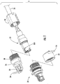
- FIG. 1 One embodiment of the multi-fiber fiber optic receptacle and plug assembly of the invention is shown in FIG. 1 with the fiber optic receptacle and corresponding fiber optic plug designated generally throughout by reference numerals 20 and 22, respectively.
- the receptacle 20 is typically mounted within a connector port defined by a wall of an enclosure, such as a connection terminal in a fiber optic communications network.
- the receptacle 20 is mounted within an opening formed through an external wall of a connection terminal so that a plug 22 mounted upon the end of a fiber optic drop cable may be readily inserted into the receptacle 20 to extend the communications network to a subscriber premises, such as a residence or business.
- the receptacle 20 and plug 22 are mated to optically connect a plurality of optical fibers of the plug 22 with a plurality of optical fibers terminated from a distribution cable within the connection terminal.
- the receptacle 20 may be mounted to other structures, such as an internal wall of a re-enterable connection terminal, or may be utilized as a stand-alone interconnection assembly, for example, in field communications to interconnect optical transmitting and receiving equipment.
- Each connector port is operable for receiving a receptacle 20 and at least one connectorized optical fiber from inside the connection terminal.
- the connector port is further operable to receive a plug 22 comprising at least one connectorized optical fiber of a drop cable that is inserted into the receptacle 20 from outside the connection terminal.
- the plug 22 is mounted upon the end portion of the drop cable and is adapted to mate with the corresponding receptacle 20.
- the plug 22 and the receptacle 20 are operable for aligning and maintaining the optical fibers in opposing relation for transmitting an optical signal.
- the opposing optical fibers are aligned and maintained in physical contact with one another.
- the end faces of the optical fibers may be angled, as will be described, to improve the optical transmission characteristics (e.g., reflectance) of the optical connection.
- the receptacle 20 and the corresponding plug 22 are shown disengaged and with the protective dust cap 24 of the receptacle 20 and the protective pulling cap 26 of the plug 22 removed.
- a threaded coupling nut 28 on the plug 22 is operable for securing the plug 22 to the receptacle 20 upon engagement and may also be used to secure the pulling cap 26 during shipping and deployment of the drop cable.
- the pulling cap 26 defines a threaded portion 30 at its rearward end and a pulling loop 32 at its forward end. The pulling cap 26 provides protection of the optical connector of the plug 22 during shipping and deployment, and until engagement of the plug 22 with the receptacle 20.
- the pulling cap 26 may be secured to the drop cable 36 using a tether 34 so that the pulling cap 26 may be reused if the plug 22 is later disengaged from the receptacle 20.
- the pulling loop 32 should be able to withstand cable-pulling forces up to about 600 lbs.
- the pulling loop 32 and the pulling cap 26 have a generally rounded forward end to facilitate deployment through conduits or ducts and over sheave wheels or pulleys.
- the receptacle 20 may also be covered and sealed with a threaded protective dust cap 24 during shipping and deployment that is removed prior to inserting the plug 22 into the receptacle 20.
- the dust cap 24 may likewise be secured to the receptacle 20 using a tether 34.
- a pre-formed, elastomeric seal boot (not shown) may provide protection for the receptacle 20 from the environment within the connection terminal and in some embodiments may also provide a sealing function.
- the protective boot allows the assembly to be installed in a breathable connection terminal or similar enclosure, and may be unnecessary in the event the receptacle 20 is otherwise reliably sealed from the environment.
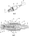
- the fiber optic plug 22 is mounted upon the end portion of the fiber optic drop cable 36 and is adapted to mate with the corresponding fiber optic receptacle 20.
- the coupling nut 28 engages the threaded end of the receptacle 20. The manner in which the receptacle and plug assembly is secured within the connector port through the external wall of the connection terminal is described below.
- FIG. 3 is a cross-sectional view of the mated receptacle 20 and plug 22 of FIG. 2 taken along line 3-3.
- the receptacle 20 includes a one-piece housing 38, a ferrule retainer 40, a multi-fiber ferrule 42, guide pins (not shown), a pin-retaining clip (not shown), a ferrule boot 44, a spring centering cuff 46, a round spring 48 and a multi-point seal 50, among other components.
- the plug 22 includes an outer housing 52, a crimp band 54, a coupling nut 28, an alignment sleeve 56 and a plug sub-assembly 86 including a crimp insert 58, an inner housing 60, a multi-fiber ferrule 43, a ferrule boot 44, a spring centering cuff 46 and a round spring 48, among other components.
- the specifics of the receptacle 20 and plug 22 components and sub-components are described in greater detail below.
- the fiber optic receptacle 20 includes a one-piece receptacle housing 38 operable for mounting within a connector port of a connection terminal or used as a stand-alone interconnection receptacle.
- the receptacle housing 38 holds a fiber optic ferrule assembly and is configured to align the ferrule assembly of the receptacle 20 with a fiber optic ferrule assembly of a corresponding fiber optic plug 22 so that they can engage in only one preferred orientation, as will be described in greater detail below with reference to FIG. 10 .
- the receptacle housing 38 defines an internal cavity 62 opening through opposed ends, a first end 64 and a second end 66.
- the opening through the first end 64 is relatively large so as to receive the corresponding fiber optic plug 22.
- the opening through the second end 66 is typically smaller and, in one advantageous embodiment, is sized to be only slightly larger than the receptacle ferrule 42, such that the ferrule 42 can be inserted through the opening.
- the relatively large opening of the first end 64 allows cleaning with a cotton swab or special cleaning tool. This is advantageous since receptacles, in contrast to fiber optic plugs, may be exposed to adverse environmental conditions, such as dust, moisture and insect infestation, while not being used for a prolonged period of time.
- the first end 64 of this embodiment allows for easy cleaning and improved access without requiring disassembly.
- the receptacle 20 of the exemplary embodiment described and shown includes a multi-fiber receptacle ferrule 42 of the Mechanical Transfer (MT) family by way of example, and not of limitation.
- the ferrule 42 includes a single row of twelve optical fibers, however, any multi-fiber connector may be used in the practice of the present invention comprising any number of optical fibers arranged in any manner.
- the fiber optic receptacle 20 may include an alignment sleeve disposed within the internal cavity 62 defined by the receptacle housing 38. In the embodiments shown throughout FIGS.
- the alignment sleeve is a component of the plug 22 and is inserted into the internal cavity 62 upon insertion of the plug 22 into the receptacle 20.
- the plug ferrule 43 is inserted into one end of the alignment sleeve, while the receptacle ferrule 42 that is mounted upon the ends of optical fibers 88 terminated from within the connection terminal (e.g., direct connectorized optical fibers from a distribution cable or a pigtail spliced to optical fibers from a distribution cable) is inserted through the opening defined by the second end 66 of the receptacle 20 and into the other end of the alignment sleeve.
- the connection terminal e.g., direct connectorized optical fibers from a distribution cable or a pigtail spliced to optical fibers from a distribution cable
- the receptacle housing 38 is cylindrical in shape and defines a shoulder portion 68 positioned medially between the first end 64 and the second end 66.
- the first end 64 of the receptacle housing 38 is inserted through an external wall of a connection terminal from inside the connection terminal until the radial surface of the shoulder portion 68 facing the first end 64 abuts the inner surface of the wall.
- a retaining ring 70 is secured around the receptacle housing 38 against the outer surface of the wall, thus retaining the wall between the retaining ring 70 and the shoulder portion 68 of the receptacle housing 38.
- the relatively low profile receptacle 20 provides strain relief against cable-pulling forces of up to about 600 lbs.
- a seal is provided between the shoulder portion 68 of receptacle housing 38 and the inner surface of the wall using an O-ring, an elastomeric ring, a multi-point seal 50 (as shown) or like sealing means.
- the receptacle housing 38 defines a circumferential groove 72 between the shoulder portion 68 and the threaded portion for receiving the multi-point seal 50.
- Another circumferential groove 74 may be provided to receive the retaining ring 70.
- a key shown in the form of a flat or partially-square shape on the shoulder portion 68, may be provided to be received within a recess having a corresponding shape formed in the inner surface of the wall, thus providing a mechanical feature that prevents the receptacle 20 from rotating within the connector port and ensuring that all receptacles 20 are installed in a desired orientation.
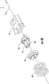
- the receptacle 20 also includes a biasing member assembly comprising a ferrule boot 44, a spring centering cuff 46 and a round coil spring 48.
- a ferrule retainer 40 functions to retain the receptacle ferrule 42 and the biasing member assembly within the interior cavity 62 of the receptacle housing 38.
- the biasing member assembly operably engages the receptacle ferrule 42 and the ferrule retainer 40 to urge the receptacle ferrule 42 toward the first end 64 of the receptacle housing 38.
- Biasing means for conventional multi-fiber connectors utilize an oval spring to fit over the rear of the ferrule boot 44, while still permitting a 12-fiber optical ribbon to pass through.
- an oval spring exhibits a different stiffness in the x and y direction that leads to the introduction of off-axis forces and possible instabilities because the spring typically does not apply its biasing force directly along the axial centerline.
- the off-center biasing force of the non-round spring creates an angularity of the end face of the ferrule 42 relative to the radial plane of the receptacle housing 38, which causes the optical fibers to be ahead of the radial plane on one side of the centerline and behind the radial plane on the opposite side of the radial plane.
- the angularity of the end face causes the forwardmost optical fibers to contact the optical fibers of the opposing ferrule although the rearward most optical fibers are not in contact.
- the round spring 48 of the present invention in conjunction with the ferrule boot 44 and the spring centering cuff 46, operate to apply a centered biasing force against the rear of the receptacle ferrule 42.
- the round spring 48, spring centering cuff 46 and the ferrule boot 44 provide a centralized force application despite the optical ribbon being situated within the center of the ferrule 42, without modifying the design and construction of conventional multi-fiber ferrules.
- the term "centralized force application” refers to the combination of structural elements that cause the resultant biasing force exerted by the round coil spring 48 on the receptacle ferrule 42 (and/or plug ferrule 43 ) to be applied along the longitudinal axis defined by the receptacle housing 38.
- the biasing force of the round spring 48 is applied at the lateral center of the ferrule end face, most preferably between the two centermost optical fiber bores.
- cylindrical receptacle housing 38 facilitates the use of a round spring 48 in a compact, yet robust receptacle and plug assembly that significantly reduces any off-center component of the biasing force with respect to conventional multi-fiber ferrule-based (e.g., MT, MPO) assemblies.
- the forward end of the round spring 48 seats against the rear of the spring centering cuff 46, which aligns the round spring 48 and couples the spring force to the ferrule boot 44.
- the spring centering cuff 46 comprises a bowl-shaped (i.e., generally concave) forward surface that bears against a domed-shaped (i.e., generally convex) rear surface on the ferrule boot 44 to provide a centralized force application to the lateral center of the end face of the ferrule 42.
- the rear surface of the ferrule boot 44 has a slightly smaller radius than the forward surface of the centering cuff 46 so that the bowl-shaped surface of the centering cuff 46 fits over the entire domed-shaped surface of the ferrule boot 44.
- the ferrule boot 44 is preferably made of a stiff elastomer, with optional low-friction properties or post-treatment, such that it will not deform under the pressure exerted by the spring 48 and can be inserted into the rear of the ferrule 42 without cracking.
- the elastomer material further provides a slight interference fit for sealing against the rear of the ferrule 42.
- the ferrule boot 44 functions to prevent epoxy from leaking between the ferrule boot 44 and the ferrule 42 and thereby avoids contamination of the pin retainer clip 78.
- the rear end of the ferrule boot 44 defines a reception window (funnel) for inserting the optical fibers 88 in both pre-assembled and discrete configurations.
- the rear of the ferrule boot 44 defines a domed-shaped surface that has its theoretical focal point aligned with the lateral center of the end face of the ferrule 42.
- the ferrule boot 44 simultaneously provides sealing, fiber guiding and centered force application functions.
- FIG. 4B an alternative embodiment of the biasing member assembly of FIG. 4A is shown.
- the domed-shaped surface of the ferrule boot 44 is replaced by a generally flat radial surface having a pair of ribs 126 that protrude rearwardly from the flat surface and are symmetrically spaced apart by about 180 degrees.
- the ribs 126 are aligned generally parallel to the lateral (i.e., height wise) Y axis of the ferrule 42 depicted in FIG. 4B .
- the ribs 126 may be generally convex and similar in curvature to the domed-shaped rear surface of the ferrule boot 44 previously described and shown in FIG.
- convex or flat ribs 126 may be provided in addition to the dome-shaped rear surface previously described.
- convex ribs 126 are typically used is conjunction with a spring centering cuff 46 having a generally concave forward surface, and flat ribs are typically used in conjunction with a spring centering cuff 46 having a flat forward surface.
- the ribs 126 function to center the biasing force of the spring 48 along the Y axis of the ferrule 42 while reducing or entirely eliminating any biasing force along the X axis of the ferrule 42 on either side of the Y axis.
- the resultant biasing force does not produce a rotational moment about the Y axis of the ferrule 42 that could lead to an undesired angularity of the end face of the ferrule 42.
- a spring biasing force that is not centered along the longitudinal axis Z of a multi-fiber ferrule, or is not balanced about the longitudinal axis Z of a multi-fiber ferrule (or at least is not balanced about the Y axis of the ferrule 42 ) will not consistently produce adequate physical contact between mating pairs of opposed optical fibers, thereby resulting in unacceptable optical characteristics of the receptacle and plug assembly.
- a conventional connector having an oval spring that applies a different resultant biasing force along its lateral (i.e., major and minor axes) may cause a rotational moment to be applied to the end face of the ferrule 42, which results in the end face of the ferrule 42 having an angularity relative to a radial plane normal to the longitudinal axis Z defined by the ferrule 42. If the end face of the ferrule 42 is rotated about the lateral axis Y, for example, certain of the mating optical fibers may lose physical contact with one another, thereby creating a gap between the optical fibers that introduces back reflection and attenuation loss.
- the biasing member assembly for centering the resultant spring biasing force along the longitudinal axis Z defined by the ferrule 42 is preferably balanced about one or both of the lateral axes X, Y defined by the end face of the ferrule 42.
- the preceding description regarding the operation of ferrule boot 44, spring centering cuff 46 and round spring 48 to center the resultant spring biasing force on receptacle ferrule 42 applies equally to plug ferrule 43 and the components 44, 46, 48 of the plug 22 may be configured the same or different than the corresponding components 44, 46, 48 of the receptacle 20.
- a pair of ferrule guide pins 76 are inserted into guide pin openings formed through the receptacle ferrule 42 and protrude a predetermined distance beyond the end face of the ferrule 42.
- the guide pins 76 are held in place with a pin retaining clip 78 that engages circumferential grooves 82 defined by the guide pins 76.
- the guide pins 76 may be inserted within corresponding guide pin openings formed through the plug ferrule 43.
- the pin retaining clip 78 is optional and may be pre-assembled on the ferrule boot 44 in order to permit post-polish insertion of the guide pins 76, if desired.
- the pin retaining clip 78 is positioned around the forward end of the ferrule boot 44.
- the alignment sleeve of the plug 22 assists in gross alignment of the mating ferrules 42, 43, while the guide pins 76 assist in fine alignment of the mating ferrules, and in particular, the opposing optical fibers of the mating ferrules.
- the guide pin holes opening through the end face of the ferrule 42 are adapted to receive a respective guide pin 76 to align the ferrule 42 with the opposing ferrule 43 in a known manner well within the ordinary skill of an artisan, and as such, need not be described further herein.
- the multi-fiber ferrule 42 is an MT-style ferrule and the body of the ferrule 42 defines at least one and, more typically, a pair of guide pin holes for receiving respective guide pins 76.
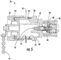
- FIG. 5 a cross-section of the receptacle 20 of FIG. 4A taken along line 5-5 is shown in an assembled configuration, with like parts indicated by like reference numbers.
- an O-ring 84 may be used to provide a seal between the protective dust cap 24 and the receptacle housing 38.
- the multi-point seal 50 is retained within the groove 72 of the receptacle housing 38 and provides multiple sealing points between the receptacle housing 38 and, for example, a wall of a connection terminal.
- the receptacle ferrule 42 is spring-biased by the round spring 48, but is allowed to float axially within the internal cavity 62 of the receptacle housing 38 to thereby absorb compressive forces between the receptacle ferrule 42 and the opposing plug ferrule 43, which is preferably spring-biased by a corresponding round spring 48.
- the round spring 48 seats against a forward radial surface of the ferrule retainer 40 such that the spring 48 is slightly pre-compressed between the ferrule retainer 40 and the spring centering cuff 46.
- the ferrule retainer 40 may be secured to the receptacle housing 38 in any suitable manner, but in one advantageous embodiment, the ferrule retainer 40 includes flexible hooks 78 that are received by features 80 ( FIG.
- the ferrule retainer 40 can be disengaged from the receptacle housing 38 in order to remove the receptacle ferrule 42, such as for cleaning, repair, replacement or the like.
- the design of the ferrule retainer 40 allows for easy removal without a special tool. Once the receptacle ferrule 42 has been cleaned, repaired or replaced, the ferrule retainer 40 can be re-engaged with the receptacle housing 38.
- the fiber optic plug 22 includes a plug sub-assembly 86, an alignment sleeve 56, an outer housing 52, a crimp band 54 and a coupling nut 26.
- a protective pulling cap 26 may be threaded onto the plug 22 using the coupling nut 28.
- the cap 26 defines a pulling loop 32, a threaded portion 30 for engaging the coupling nut 28 and a tether 34 that may be attached to the drop cable 36 to retain the pulling cap 26 with the plug 22.
- a molded-on plug boot (not shown) made of a flexible (silicone-type or other like) material secured over a rear portion of the outer housing 52 and a portion of the drop cable 36 in order to seal the exposed portion of the drop cable 36 while generally inhibiting kinking and providing bending strain relief to the cable 36 near the plug 22.
- the strength components 90 are terminated and a crimp band 54 is secured around the strength components 90.
- the crimp band 54 is preferably made from brass, but other suitable deformable materials may be used.
- the strength members (not shown) are cut flush with the stripped back cable jacket 92, thereby exposing the GRP strength components 90 and an optical fiber ribbon comprising a plurality of ribbonized optical fibers 94.
- the crimp band 54 provides strain relief for the cable 36.
- the plug sub-assembly 86 is assembled by first crimping the crimp band 54 around a rear knurled portion. As is well understood by those of ordinary skill in the art, the outer housing 52 and the coupling nut 28 are threaded onto the cable 36 before the sub-assembly 86. The outer housing 52 is then slid over the plug sub-assembly 86.
- the alignment sleeve 56 defines a lengthwise passageway 98 for receiving the plug ferrule 43 and the receptacle ferrule 42 when the plug 22 is mated with the receptacle 20.
- the alignment sleeve 74 may be a component of either the receptacle 20 or the plug 22. In the exemplary embodiment shown and described herein the alignment sleeve 74 is a component of the plug 22.
- the outer housing 52 has a generally cylindrical shape with a forward first end 100 and a rearward second end 102. The outer housing 52 generally protects the plug sub-assembly 86 and in preferred embodiments also aligns and keys engagement of the plug 22 with the mating receptacle 20.
- the outer housing 52 includes a through passageway between the first and second ends 100 and 102.
- the passageway of the outer housing 52 includes an alignment and keying feature so that the plug sub-assembly 86 is inhibited from rotating once the plug 22 is assembled.
- the first end 100 of the outer housing 52 includes a key slot (see FIGS. 1 and 10 at reference numeral 104 ) for aligning the plug 22 with the receptacle 20, and consequently, the plug sub-assembly 86 relative to the receptacle 20.
- the plug 22 and the corresponding receptacle 20 are configured to permit mating in only one orientation.
- this orientation may be marked on the receptacle 20 and on the plug 22 using alignment indicia so that a less skilled field technician can readily mate the plug 22 with the receptacle 20. Any suitable indicia may be used.
- the field technician engages the internal threads of the coupling nut 28 with the external threads of the receptacle 20 to secure the plug 22 to the receptacle 20.
- the outer housing 52 of the plug 22 may further define a shoulder 106 that serves as a mechanical stop for a conventional elastomeric O-ring 96 against a forward radial surface thereof and for the coupling nut 28 against a rearward radial surface thereof.
- the O-ring 96 provides an environmental seal when the coupling nut 28 engages the threaded portion of the receptacle housing 38.
- the coupling nut 28 has a passageway sized to loosely fit over the second end 102 and the shoulder 106 of the outer housing 52 so that the coupling nut 28 easily rotates about the outer housing 52.
- FIG. 7 is a cross-section of the plug 22 of FIG. 6 taken along line 7-7 and shown in an assembled configuration with like parts indicated by like reference numbers.
- Plug sub-assembly 86 comprises the multi-fiber ferrule 43, the ferrule boot 44, the spring centering cuff 46, the round spring 48, the crimp insert 58 and the inner housing 60, as previously described.
- the plug ferrule 43 is at least partially disposed within the inner housing 60, extends lengthwise and protrudes outwardly therefrom into the alignment sleeve 56.
- the plug ferrule 43 is mounted within the inner housing 60 such that the end face of the plug ferrule 43 extends somewhat beyond the forward end of the inner housing 60.
- the fiber optic plug 22 includes a corresponding multi-fiber ferrule 43, preferably of like configuration.
- the plug 22 of the exemplary embodiment is shown to include a single 12-fiber MT-style ferrule 43.
- the plug sub-assembly 86 may also include an elastomeric O-ring 108 that seats within a groove 110 defined by the crimp insert 58.
- the O-ring 108 serves to provide a seal between the crimp insert 58 and the plug outer housing 52 when the coupling nut 28 engages the threaded portion of the protective pulling cap 26 or the receptacle 20.
- the plug 22 likewise includes the biasing member assembly comprising the round spring 48, the spring centering cuff 46 and the ferrule boot 44.
- the biasing member assembly operably engages the plug ferrule 43 and a radial surface provided on the forward end of the crimp insert 58 to urge the plug ferrule 43 toward the first end 100 of the outer housing 52.
- the round spring 48 in conjunction with the ferrule boot 44 and the spring centering cuff 46 are operable in the manner described above to apply a spring biasing force that is centered on the end face of the plug ferrule 43.
- the biasing force of the spring 48 is applied on the end face of the ferrule 43 along the longitudinal axis defined by the plug 22, or is balanced about one or more lateral axes defined by the end face of the plug ferrule 43 such that the resultant biasing force causes the plane defined by the end face of the ferrule to be substantially normal to the longitudinal axis defined by the plug 22.
- the forward end of the round spring 48 seats against the rear of the spring centering cuff 46, which aligns the round spring 48 and couples the spring force to the ferrule boot 44.
- the spring centering cuff 46 comprises a bowl-shaped (i.e., generally concave) forward surface that bears against a domed-shaped (i.e., generally convex) rear surface on the ferrule boot 44 to provide a centralized force application to the lateral center of the end face of the ferrule 43.
- the rear surface of the ferrule boot 44 has a slightly smaller radius than the forward surface of the centering cuff 46 so that the bowl-shaped surface of the centering cuff 46 fits over the entire domed-shaped surface of the ferrule boot 44. The lower the friction between the spring centering cuff 46 and the ferrule boot 44, the more centered the resulting biasing force will be relative to the optical fiber array.
- the ferrule boot 44 is preferably made of a stiff elastomer, with optional low-friction properties or post-treatment, such that it will not deform under the pressure exerted by the spring 48 and can be inserted into the rear of the ferrule 43 without cracking.
- the elastomer material further provides a slight interference fit for sealing against the rear of the ferrule 43.
- the ferrule boot 44 functions to prevent epoxy from leaking between the ferrule boot 44 and the plug ferrule 43.
- the rear end of the ferrule boot 44 defines a reception window (funnel) for inserting the optical fibers 94 in both pre-assembled and discrete configurations.
- the rear of the ferrule boot 44 defines a domed-shaped surface that has its theoretical focal point aligned with the lateral center of the end face of the ferrule 43.
- the ferrule boot 44 simultaneously provides sealing, fiber guiding and centered force application functions.
- the plug ferrule 43 is spring-biased by the round spring 48, but is allowed to float axially within the inner housing 60 and the alignment sleeve 56 to thereby absorb compressive forces between the plug ferrule 43 and the opposing receptacle ferrule 42, which is preferably spring-biased by a corresponding round spring 48.
- the round spring 48 seats against a forward radial surface of the crimp insert 58 such that the spring 48 is slightly pre-compressed between the crimp insert 58 and the spring centering cuff 46.
- the spring centering cuff 46 seats against the bearing surface of the ferrule boot 44 to center the resultant spring biasing force on the center of the end face of the plug ferrule 43.
- FIG. 9 is a cross-section of the plug sub-assembly 86 of FIG. 8 taken along line 9-9 shown in an assembled configuration with like parts indicated by like reference numbers.
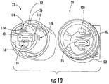
- FIG. 10 an end view of the receptacle 20 and plug 22 of FIG. 1 is shown disengaged in order to illustrate alignment and keying features of the assembly.
- the plug 22 engages the receptacle 20 to optically connect the optical fibers of the plug ferrule 43 and the corresponding receptacle ferrule 42.
- the alignment sleeve 56 is retained and positioned within the outer housing 52 of the plug 22 such that the key slot 114 of the alignment sleeve 56 is aligned with the key slot 104 defined by the plug outer housing 52.
- the plug outer housing 52 defines a pair of openings 116 along its length adjacent the first end 100 for receiving features 118 defined by the alignment sleeve 56. The features 118 are received by the openings 116 in order to properly align the alignment sleeve 56 within the plug outer housing 52, thus aligning the key slot 114 of the alignment sleeve 56 with the key slot 104 of the outer housing 52.
- the plug 22 is inserted into the receptacle 20.
- the receptacle 20 may only receive a plug 22 of like ferrule configuration.
- the receptacle 20 defines a first key 120 that is received within the key slot 104 of the plug outer housing 52 and the key slot 114 of the alignment sleeve 56.
- the key 120 is a protruding feature that is molded into the receptacle housing 38 of the receptacle 20.
- Receptacles having specific key shapes may be created for each type of multi-fiber receptacle ferrule 42 and plug ferrule 43 pair.
- the receptacle 20 further defines a second protruding feature 122 that excludes a non-conforming alignment sleeve 56 to prevent a dissimilar plug ferrule 43 from being inserted into the receptacle 20 and mated with the receptacle ferrule 42.
- the alignment sleeve 56 of the plug 22 defines an opening 124 for receiving the second protruding feature 122 (also referred to herein as the "excluding feature 122 ").
- the key 120 and the excluding feature 122 prevent rotation of the outer housing 52 relative to the receptacle housing 38 of the receptacle 20, while the guide pins 76 align the receptacle and plug ferrules 42, 43. Because the alignment and keying features extend to about the end of the plug 22, a plug 22 having a ferrule configuration different than the receptacle 20 is prevented from being inserted into the receptacle 20 prior to physical contact between the receptacle ferrule 42 and the plug ferrule 43, thereby eliminating potential damage to the end faces. Proper alignment is also important when mating multiple fibers in order to assure optimum optical transmission characteristics between opposing pairs of the optical fibers 88, 94.
- the threads of the coupling nut 28 and the receptacle housing 38 may be replaced with a bayonet or push-pull mechanism to secure the plug 22 within the receptacle 20.
- a spring clip or similar device may be added to engage the plug 22 with the receptacle 20 to secure them together. Sealing may be removed or relaxed based upon the extent of the adverse environment to which the assembly is exposed.
- the optional plug boot may be premanufactured and assembled onto the crimp insert 58 and the drop cable 36, or may be overmolded using a technology available from Corning Cable Systems LLC of Hickory, North Carolina. Further, heat shrinkable tubing may be used to fulfill the same purpose as the boot when aesthetics are less important and bend characteristics less stringent.
- the alignment sleeve 56 may be integrated into the receptacle 20 while maintaining the same assembly technique and allowing for easy removal and cleaning of the receptacle ferrule 42.
- Multi-fiber ferrule designs can be derived from the basic design shown and described herein. Multi-fiber ferrule designs driven by the available space and requirements are possible. Additional strain relief may be added to the receptacle 20 if needed. Crimping solutions may differ depending on the drop cable type and requirements. If the drop cable does not include the dual GRP dielectric strength members as shown, the methods of coupling the strength member(s) to the plug body may include glue or other means of fastening, such as clamps.
- the embodiments described above provide advantages over conventional multi-fiber fiber optic receptacle and plug assemblies.
- the compact size of the exemplary embodiments described herein allows for about a 38mm diameter package for FTTx drop cables and allows multiple receptacles to be mounted in connection terminals or other enclosures, while requiring very little penetration depth of the receptacle into the terminal or enclosure.
- the alignment and keying features of these assemblies makes them fully APC capable, and the unique fit prevents assembly errors during production and installation.
- An overmolded boot eliminates the need for heat shrinkable tubing and also improves the sealing integrity of the assembly under adverse conditions in which a pre-formed boot may disengage from the plug 22.
- the present invention provides multi-fiber fiber optic receptacle and plug assemblies including like multi-fiber optical connectors, such as MT-style or MPO-style technology connectors.
- the rigid shoulder 68 of the receptacle 20 is mounted against the inner surface of the wall of the terminal, thus providing superior retention for external pulling forces as compared to conventional threaded designs that use a nut on the inside of the wall for securing the receptacle 20.
- the fiber optic receptacle 20 and plug 22 assembly of the present invention provides a sealed design that prevents moisture and contamination from reaching the ferrule end faces.
- O-rings provide static seals, and their position combined with relief features minimize vacuum build-up when removing the plug 22 from the receptacle 20 and pressure build-up when inserting the plug 22 into the receptacle 20.
- the polymer is a UV stabilized polymer such as ULTEM 2210 available from GE Plastics, however, other suitable materials made also be used. For example, stainless steel or other suitable metals and plastics may be used.
Landscapes
- Physics & Mathematics (AREA)
- General Physics & Mathematics (AREA)
- Optics & Photonics (AREA)
- Mechanical Coupling Of Light Guides (AREA)
Claims (4)
- Faseroptische Anordnung einer Buchse (20) und eines Steckers (22) für mehrere Fasern, die Folgendes umfasst:eine faseroptische Buchse (20), die ein erstes Ausricht- und Verzahnungsmerkmal definiert, wobei die Buchse Folgendes enthält:ein Buchsengehäuse (38), das einen inneren Hohlraum (62) definiert;einen Ferrulenhalter (40), der an dem Buchsengehäuse (38) befestigt ist;eine Buchsenferrule (42), die wenigstens teilweise in dem inneren Hohlraum (62) des Buchsengehäuses (38) angeordnet ist und wenigstens teilweise in dem Ferrulenhalter (40) angeordnet ist; undeine Vorbelastungsfeder (48), um die Buchsenferrule (42) in Richtung des Buchsengehäuses (38) vorzubelasten; undeinen faseroptischen Stecker (22), der dafür ausgelegt ist, mit der Buchse (20) gekoppelt zu werden, und ein komplementäres zweites Ausricht- und Verzahnungsmerkmal definiert, wobei der Stecker Folgendes enthält:ein Steckeraußengehäuse (52), das einen Durchgang definiert;eine Stecker-Unteranordnung, die in dem Durchgang angeordnet ist und ein inneres Gehäuse (60), eine Steckerferrule (43) und eine Vorbelastungsfeder (48) aufweist, wobei die Steckerferrule (43) wenigstens teilweise in dem inneren Gehäuse (60) angeordnet ist; undeine Ausrichthülse (56), die in der Nähe eines vorderen Endes des inneren Gehäuses (60) angeordnet ist, wobei die Steckerferrule (43) wenigstens teilweise in der Ausrichthülse (56) angeordnet ist, wobei die Ausrichthülse (56) mit dem Steckeraußengehäuse (52) so gehalten und positioniert ist, dass ein Verzahnungsschlitz (114) der Ausrichthülse (56) auf einen Verzahnungsschlitz (104), der durch das Steckeraußengehäuse (52) definiert ist, ausgerichtet ist; undwobei das zweite Ausricht- und Verzahnungsmerkmal des Steckers mit dem ersten Ausricht- und Verzahnungsmerkmal der Buchse (20) betriebstechnisch in Eingriff ist, wenn der Stecker (22) in die Buchse (20) eingesetzt ist, um die Buchsenferrule (42) und die Steckerferrule (43) in einer gegenüberliegenden Beziehung geeignet auszurichten.
- Faseroptische Anordnung einer Buchse und eines Steckers für mehrere Fasern nach Anspruch 1, wobei die Buchse (20) und der Stecker (22) ferner jeweils eine Hülsenmanschette (44), die mit dem hinteren Ende der Buchsenferrule (42) bzw. der Steckerferrule (43) in Eingriff sind, und einen Federzentrierbund (46), der mit der hinteren Oberfläche der entsprechenden Hülsenmanschette (44) in Eingriff ist, enthalten, und wobei die Vorbelastungsfeder (48), der Federzentrierbund (46) und die Ferrulenmanschette (44) der Buchse (20) und des Steckers (22) mit dem hinteren Ende der Buchsenferrule (42) bzw. der Steckerferrule betriebstechnisch in Eingriff sind, um eine Federvorbelastungskraft im Wesentlichen auf die Mitte einer Stirnfläche der Buchsenferrule (42) bzw. der Steckerferrule (43) zu zentrieren.
- Faseroptische Anordnung einer Buchse und eines Steckers für mehrere Fasern nach Anspruch 1, wobei die Buchsenferrule (42) und die Steckerferrule (43) jeweils Mehrfaserferrulen mit ähnlicher Konfiguration sind und wobei das wenigstens eine Ausricht- und Verzahnungsmerkmal der Buchse (20) ferner ein Ausschlussmerkmal aufweist, um zu verhindern, dass eine Steckerferrule (43) mit unähnlicher Konfiguration in die Buchse (20) eingesetzt und mit der Buchsenferrule (42) gekoppelt wird.
- Faseroptische Anordnung einer Buchse und eines Steckers für mehrere Fasern nach Anspruch 1, wobei das Buchsengehäuse (38) einen Gewindeabschnitt aufweist und wobei der Stecker (22) eine Gewindekopplungsmutter (28) für einen Eingriff mit dem Gewindeabschnitt der Buchse (20) aufweist, um den Stecker (22) an der Buchse (20) zu befestigen.
Priority Applications (1)
| Application Number | Priority Date | Filing Date | Title |
|---|---|---|---|
| PL16158168T PL3064973T3 (pl) | 2005-03-10 | 2005-03-30 | Wielowłóknowy światłowodowy zespół wtyczki i gniazda |
Applications Claiming Priority (3)
| Application Number | Priority Date | Filing Date | Title |
|---|---|---|---|
| US11/076,684 US7264402B2 (en) | 2005-03-10 | 2005-03-10 | Multi-fiber optic receptacle and plug assembly |
| PCT/US2005/010728 WO2006098734A1 (en) | 2005-03-10 | 2005-03-30 | Multi-fiber fiber optic receptacle and plug assembly |
| EP05731128.4A EP1861739B1 (de) | 2005-03-10 | 2005-03-30 | Faseroptische mehrfaser-buchsen- und steckerbaugruppe |
Related Parent Applications (2)
| Application Number | Title | Priority Date | Filing Date |
|---|---|---|---|
| EP05731128.4A Division EP1861739B1 (de) | 2005-03-10 | 2005-03-30 | Faseroptische mehrfaser-buchsen- und steckerbaugruppe |
| EP05731128.4A Division-Into EP1861739B1 (de) | 2005-03-10 | 2005-03-30 | Faseroptische mehrfaser-buchsen- und steckerbaugruppe |
Publications (3)
| Publication Number | Publication Date |
|---|---|
| EP3064973A2 EP3064973A2 (de) | 2016-09-07 |
| EP3064973A3 EP3064973A3 (de) | 2017-01-04 |
| EP3064973B1 true EP3064973B1 (de) | 2020-05-13 |
Family
ID=34964333
Family Applications (3)
| Application Number | Title | Priority Date | Filing Date |
|---|---|---|---|
| EP05731128.4A Expired - Lifetime EP1861739B1 (de) | 2005-03-10 | 2005-03-30 | Faseroptische mehrfaser-buchsen- und steckerbaugruppe |
| EP16158168.1A Expired - Lifetime EP3064973B1 (de) | 2005-03-10 | 2005-03-30 | Mehrfaseroptische steckdosen- und steckeranordnung |
| EP10012114.4A Expired - Lifetime EP2312354B1 (de) | 2005-03-10 | 2005-03-30 | Mehrfaseroptische Steckdosen- und Steckeranordnung |
Family Applications Before (1)
| Application Number | Title | Priority Date | Filing Date |
|---|---|---|---|
| EP05731128.4A Expired - Lifetime EP1861739B1 (de) | 2005-03-10 | 2005-03-30 | Faseroptische mehrfaser-buchsen- und steckerbaugruppe |
Family Applications After (1)
| Application Number | Title | Priority Date | Filing Date |
|---|---|---|---|
| EP10012114.4A Expired - Lifetime EP2312354B1 (de) | 2005-03-10 | 2005-03-30 | Mehrfaseroptische Steckdosen- und Steckeranordnung |
Country Status (12)
| Country | Link |
|---|---|
| US (2) | US7264402B2 (de) |
| EP (3) | EP1861739B1 (de) |
| JP (1) | JP4801664B2 (de) |
| CN (4) | CN102778731B (de) |
| AU (3) | AU2005329050B2 (de) |
| CA (2) | CA2732530C (de) |
| ES (3) | ES2618555T3 (de) |
| HU (1) | HUE031752T2 (de) |
| MX (1) | MX2007010834A (de) |
| PL (3) | PL3064973T3 (de) |
| PT (3) | PT3064973T (de) |
| WO (1) | WO2006098734A1 (de) |
Families Citing this family (243)
| Publication number | Priority date | Publication date | Assignee | Title |
|---|---|---|---|---|
| US6996480B2 (en) | 2002-06-14 | 2006-02-07 | University Of South Carolina | Structural health monitoring system utilizing guided lamb waves embedded ultrasonic structural radar |
| US6962445B2 (en) | 2003-09-08 | 2005-11-08 | Adc Telecommunications, Inc. | Ruggedized fiber optic connection |
| KR100507543B1 (ko) * | 2004-06-30 | 2005-08-09 | 주식회사 골드텔 | 광커넥터 |
| DE102005000925A1 (de) * | 2005-01-07 | 2006-07-20 | Infineon Technologies Fiber Optics Gmbh | Bauteil und Verfahren zur exzentrischen Ausrichtung eines ersten und eines zweiten Stifts, die jeweils eine Lichtleitfaser zentrisch enthalten, sowie Modulvorsatz und Steckerkopplung mit meinem solchen Bauteil |
| US7785019B2 (en) * | 2005-03-10 | 2010-08-31 | Corning Cable Systems Llc | Multi-fiber fiber optic receptacle and plug assembly |
| US7264402B2 (en) * | 2005-03-10 | 2007-09-04 | Corning Cable Systems Llc | Multi-fiber optic receptacle and plug assembly |
| US7481584B2 (en) * | 2006-06-30 | 2009-01-27 | Ocean Design, Inc. | Dry mate connector |
| US7568844B2 (en) * | 2006-08-15 | 2009-08-04 | Corning Cable Systems Llc | Ruggedized fiber optic connector assembly |
| US7985027B2 (en) * | 2006-11-14 | 2011-07-26 | Corning Cable Systems Llc | Adapter assembly for coupling dissimilar fiber optic connectors |
| US7347630B1 (en) * | 2006-12-06 | 2008-03-25 | Avago Technologies Fiber Ip Pte Ltd. | Fiber optic transceiver having a floating transmitter port |
| US7519258B2 (en) * | 2006-12-21 | 2009-04-14 | Corning Cable Systems Llc | Preconnectorized fiber optic local convergence points |
| US7572065B2 (en) * | 2007-01-24 | 2009-08-11 | Adc Telecommunications, Inc. | Hardened fiber optic connector |
| US7591595B2 (en) | 2007-01-24 | 2009-09-22 | Adc Telelcommunications, Inc. | Hardened fiber optic adapter |
| US7614797B2 (en) * | 2007-01-24 | 2009-11-10 | Adc Telecommunications, Inc. | Fiber optic connector mechanical interface converter |
| US7540666B2 (en) * | 2007-02-27 | 2009-06-02 | Corning Cable Systems Llc | Articulated force application for multi-fiber ferrules |
| US7785016B2 (en) * | 2007-03-12 | 2010-08-31 | Corning Cable Systems Llc | Fiber optic adapter and connector assemblies |
| US7556437B2 (en) * | 2007-03-13 | 2009-07-07 | Adc Telecommunications, Inc. | Fiber optic connector with protective cap |
| US7585116B2 (en) * | 2007-04-12 | 2009-09-08 | Fiber Systems International | Fiber optic connector having hermaphroditic coupling mechanism |
| JP4957363B2 (ja) * | 2007-05-02 | 2012-06-20 | 住友電気工業株式会社 | 光コネクタ及び光コネクタの組立方法 |
| WO2008137897A1 (en) | 2007-05-06 | 2008-11-13 | Adc Telecommunications, Inc. | Mechanical interface converter for making non-ruggedized fiber optic connectors compatible with a ruggedized fiber optic adapter |
| WO2008137893A1 (en) | 2007-05-06 | 2008-11-13 | Adc Telecommunications, Inc. | Interface converter for sc fiber optic connectors |
| US20080298748A1 (en) | 2007-05-31 | 2008-12-04 | Terry Dean Cox | Direct-connect optical splitter module |
| US7686519B2 (en) | 2007-06-18 | 2010-03-30 | Adc Telecommunications, Inc. | Hardened fiber optic housing and cable assembly |
| CN101828137B (zh) | 2007-08-30 | 2012-09-19 | 胡贝尔和茹纳股份公司 | 具有光束扩展装置的光纤接插式连接器 |
| US8798427B2 (en) | 2007-09-05 | 2014-08-05 | Corning Cable Systems Llc | Fiber optic terminal assembly |
| US7744286B2 (en) | 2007-12-11 | 2010-06-29 | Adc Telecommunications, Inc. | Hardened fiber optic connection system with multiple configurations |
| US7758389B2 (en) | 2008-01-25 | 2010-07-20 | Tyco Electronics Corporation | Connector assembly having a movable plug |
| US8036504B2 (en) * | 2008-01-25 | 2011-10-11 | Adc Telecommunications, Inc. | Loop back device and method of fabrication |
| US7837396B2 (en) * | 2008-03-13 | 2010-11-23 | Adc Telecommunications, Inc. | Attachment of a connector to a fiber optic cable |
| US7708469B2 (en) * | 2008-04-11 | 2010-05-04 | Corning Cable Systems Llc | Fiber optic connector assembly and method for venting gas inside a fiber optic connector sub-assembly |
| JP4577793B2 (ja) * | 2008-06-04 | 2010-11-10 | ヒロセ電機株式会社 | 防水コネクタ、及び、この防水コネクタを用いた防水装置 |
| US8620130B2 (en) * | 2008-08-29 | 2013-12-31 | Corning Cable Systems Llc | Pulling grips for installing a fiber optic assembly |
| US8272792B2 (en) * | 2008-09-30 | 2012-09-25 | Corning Cable Systems Llc | Retention bodies for fiber optic cable assemblies |
| US8303193B2 (en) * | 2008-09-30 | 2012-11-06 | Corning Cable Systems Llc | Retention bodies for fiber optic cable assemblies |
| US8285096B2 (en) | 2008-09-30 | 2012-10-09 | Corning Cable Systems Llc | Fiber optic cable assemblies and securing methods |
| EP2344915A4 (de) | 2008-10-09 | 2015-01-21 | Corning Cable Sys Llc | Faseroptischer anschluss mit adaptertafel, die sowohl eingangs- als auch ausgangsfasern von einem optischen teiler unterstützt |
| US8879882B2 (en) | 2008-10-27 | 2014-11-04 | Corning Cable Systems Llc | Variably configurable and modular local convergence point |
| JP4651056B2 (ja) * | 2008-10-28 | 2011-03-16 | 日本航空電子工業株式会社 | アダプタ装置 |
| US7941021B2 (en) * | 2008-12-22 | 2011-05-10 | Corning Cable Systems Llc | Distribution cable assembly having mid-span access location |
| US8413961B2 (en) * | 2009-01-09 | 2013-04-09 | Belkin International Inc. | Cable pulling cap, method of manufacture, and method of use |
| EP2237091A1 (de) | 2009-03-31 | 2010-10-06 | Corning Cable Systems LLC | Lösbar montierbares LWL-Leitungsendgerät |
| JP5631979B2 (ja) * | 2009-04-27 | 2014-11-26 | ピコメトリクス、エルエルシー | ファイバにより光結合されたタイムドメイン・テラヘルツシステム内でファイバの延伸により誘起されるタイミングエラーを低減するシステムと方法 |
| US20100303431A1 (en) | 2009-05-29 | 2010-12-02 | Cox Terry D | Fiber Optic Harnesses and Assemblies Facilitating Use of a Pre-Connectorized Fiber Optic Cable(s) with a Fiber Optic Terminal |
| WO2010138694A1 (en) | 2009-05-29 | 2010-12-02 | Corning Cable Systems Llc | Dust cap assembly for sealing an optical fiber ferrule and methods thereof |
| GB2473818A (en) * | 2009-09-21 | 2011-03-30 | Volex Europ Ltd | Optical-fibre connector |
| PL2759860T3 (pl) | 2009-09-28 | 2018-07-31 | Te Connectivity Nederland B.V. | Obudowa uszczelniająca dla złącza na kablu, takiego jak standardowe złącze światłowodowe |
| US8467651B2 (en) * | 2009-09-30 | 2013-06-18 | Ccs Technology Inc. | Fiber optic terminals configured to dispose a fiber optic connection panel(s) within an optical fiber perimeter and related methods |
| US20110097039A1 (en) * | 2009-10-28 | 2011-04-28 | Hon Hai Precision Ind. Co., Ltd. | Optoelectronic interconnection system |
| US8500341B2 (en) * | 2009-11-20 | 2013-08-06 | Adc Telecommunications, Inc. | Fiber optic cable assembly |
| US8597050B2 (en) * | 2009-12-21 | 2013-12-03 | Corning Gilbert Inc. | Digital, small signal and RF microwave coaxial subminiature push-on differential pair system |
| JP5448885B2 (ja) * | 2010-01-28 | 2014-03-19 | 富士フイルム株式会社 | 医療機器及び内視鏡装置 |
| PT2355286T (pt) | 2010-01-29 | 2019-05-08 | Tyco Electronics Raychem Bvba | Dispositivo de impermeabilização e retenção de cabos |
| EP2355283A1 (de) | 2010-01-29 | 2011-08-10 | Tyco Electronics Raychem BVBA | Kabelabdichtungsvorrichtung, Kabelabschluss und Befestigungsvorrichtung |
| ES2755911T3 (es) | 2010-02-04 | 2020-04-24 | Commscope Technologies Llc | Sistema de conexión de fibra óptica y eléctrica reforzado |
| US8649649B2 (en) | 2010-03-03 | 2014-02-11 | Adc Telecommunications, Inc. | Fiber distribution hub with connectorized stub cables |
| US9547144B2 (en) | 2010-03-16 | 2017-01-17 | Corning Optical Communications LLC | Fiber optic distribution network for multiple dwelling units |
| US20110235986A1 (en) * | 2010-03-24 | 2011-09-29 | Adc Telecommunications, Inc. | Optical fiber drawer with connectorized stub cable |
| US9078287B2 (en) | 2010-04-14 | 2015-07-07 | Adc Telecommunications, Inc. | Fiber to the antenna |
| US8792767B2 (en) | 2010-04-16 | 2014-07-29 | Ccs Technology, Inc. | Distribution device |
| US8915659B2 (en) | 2010-05-14 | 2014-12-23 | Adc Telecommunications, Inc. | Splice enclosure arrangement for fiber optic cables |
| US8821034B2 (en) * | 2010-06-30 | 2014-09-02 | Panduit Corp. | MPO type connector with reduced off-center loading |
| CN101907750B (zh) * | 2010-07-31 | 2012-12-26 | 中航光电科技股份有限公司 | 光纤连接器组件及其插头 |
| WO2012018787A2 (en) | 2010-08-02 | 2012-02-09 | Adc Telecommunications, Inc. | Cable spool assembly |
| CN101923192B (zh) * | 2010-08-18 | 2012-01-25 | 中航光电科技股份有限公司 | Dlc光纤连接器组件及其插头 |
| US8221006B2 (en) | 2010-08-23 | 2012-07-17 | Corning Cable Systems Llc | Fiber optic cable assemblies with mechanically interlocking crimp bands and methods of making the assemblies |
| WO2012036982A2 (en) | 2010-09-14 | 2012-03-22 | Adc Telecommunications, Inc. | A method of terminating a fiber optic cable |
| WO2012044741A1 (en) * | 2010-10-01 | 2012-04-05 | Corning Cable Systems Llc | Transformable ferrule assemblies and fiber optic connectors |
| US9720197B2 (en) | 2010-10-19 | 2017-08-01 | Corning Optical Communications LLC | Transition box for multiple dwelling unit fiber optic distribution network |
| JP5356355B2 (ja) * | 2010-10-19 | 2013-12-04 | 古河電気工業株式会社 | 光ファイバ端子固定部材、光コネクタ、およびコネクタ付光ファイバケーブル |
| US8885998B2 (en) | 2010-12-09 | 2014-11-11 | Adc Telecommunications, Inc. | Splice enclosure arrangement for fiber optic cables |
| US8873922B2 (en) | 2010-12-20 | 2014-10-28 | Adc Telecommunications, Inc. | Fan-out and parking module |
| US8861919B2 (en) | 2011-02-16 | 2014-10-14 | Tyco Electronics Corporation | Fiber optic closure |
| DE102011011523B4 (de) | 2011-02-17 | 2013-05-29 | Tyco Electronics Services Gmbh | Faseroptische Verbindungsanordnung und Adapterhülse |
| US20120275753A1 (en) * | 2011-04-28 | 2012-11-01 | Reinhardt Sherrh C | Fiber assembly with tray feature |
| WO2013016135A2 (en) | 2011-07-22 | 2013-01-31 | Adc Telecommunications, Inc. | Fiber optic connector and cable assembly having a fiber locking mechanism |
| US8540435B2 (en) * | 2011-07-22 | 2013-09-24 | Corning Cable Systems Llc | Ferrule retainers having access window(s) for accessing and/or referencing a fiber optic ferrule, and related fiber optic connector assemblies, connectors, and referencing methods |
| WO2013019465A1 (en) | 2011-07-29 | 2013-02-07 | Corning Cable Systems Llc | Fiber optic cable assemblies having a connector with a stable fiber length therein |
| US8622634B2 (en) | 2011-07-29 | 2014-01-07 | Corning Cable Systems Llc | Optical fiber assemblies and methods of fabricating optical fiber assemblies |
| EP2745155B1 (de) | 2011-08-16 | 2019-11-20 | Corning Optical Communications LLC | Anschliessbare kabelanordnungen für innen- und aussenanwendungen |
| CN104041066A (zh) | 2011-10-03 | 2014-09-10 | 蒂科电子瑞侃有限公司 | 用于户外高架场所的集线箱 |
| JP5826594B2 (ja) * | 2011-10-28 | 2015-12-02 | 日本航空電子工業株式会社 | コネクタ |
| US20130108220A1 (en) | 2011-10-31 | 2013-05-02 | Marco Antonio Gonzalez Garcia | Systems and methods for providing a ferrule boot |
| WO2013077969A1 (en) | 2011-11-23 | 2013-05-30 | Adc Telecommunications, Inc. | Multi-fiber fiber optic connector |
| US8534928B2 (en) | 2011-11-28 | 2013-09-17 | Corning Cable Systems Llc | Optical fiber assemblies, optical fiber organizers and methods of fabricating optical fiber assemblies |
| US9219546B2 (en) | 2011-12-12 | 2015-12-22 | Corning Optical Communications LLC | Extremely high frequency (EHF) distributed antenna systems, and related components and methods |
| US8678668B2 (en) | 2012-01-30 | 2014-03-25 | Corning Cable Systems Llc | Overmolded ferrule boot and methods for making the same |
| WO2013117589A2 (en) | 2012-02-07 | 2013-08-15 | Tyco Electronics Raychem Bvba | Cable termination assembly and method for connectors |
| WO2013122752A1 (en) | 2012-02-13 | 2013-08-22 | Corning Cable Systems Llc | Fiber optic cable sub -assemblies and methods of making said sub -assemblies |
| EP3650898B1 (de) | 2012-02-20 | 2022-08-03 | Commscope Technologies LLC | Faseroptische anordnung |
| US10110307B2 (en) | 2012-03-02 | 2018-10-23 | Corning Optical Communications LLC | Optical network units (ONUs) for high bandwidth connectivity, and related components and methods |
| US9004778B2 (en) | 2012-06-29 | 2015-04-14 | Corning Cable Systems Llc | Indexable optical fiber connectors and optical fiber connector arrays |
| US9696500B2 (en) | 2012-08-31 | 2017-07-04 | Corning Optical Communications LLC | Female hardened optical connectors for use with hybrid receptacle |
| US9049500B2 (en) | 2012-08-31 | 2015-06-02 | Corning Cable Systems Llc | Fiber optic terminals, systems, and methods for network service management |
| CN102854579B (zh) * | 2012-09-06 | 2016-04-20 | 深圳日海通讯技术股份有限公司 | 具有一体式外壳的光纤接入插头 |
| US8939654B2 (en) * | 2012-09-27 | 2015-01-27 | Adc Telecommunications, Inc. | Ruggedized multi-fiber fiber optic connector with sealed dust cap |
| US8909019B2 (en) | 2012-10-11 | 2014-12-09 | Ccs Technology, Inc. | System comprising a plurality of distribution devices and distribution device |
| CN203054267U (zh) * | 2012-12-14 | 2013-07-10 | 泰科电子(上海)有限公司 | 防尘装置和连接器组件 |
| AU2014275486B2 (en) | 2013-03-18 | 2017-07-27 | Commscope Technologies Llc | Architecture for a wireless network |
| JP2016514863A (ja) * | 2013-04-15 | 2016-05-23 | フーバー + スーナー アーゲー | 光コネクタ組立体 |
| WO2014179376A2 (en) | 2013-05-02 | 2014-11-06 | Corning Optical Communications LLC | Connector assemblies and methods for providing sealing and strain-relief |
| WO2014209671A2 (en) * | 2013-06-25 | 2014-12-31 | Corning Optical Communications LLC | Optical plug having a translating cover and a complimentary receptacle |
| US10444443B2 (en) | 2013-06-27 | 2019-10-15 | CommScope Connectivity Belgium BVBA | Fiber optic cable anchoring device for use with fiber optic connectors and methods of using the same |
| US9804348B2 (en) * | 2013-07-04 | 2017-10-31 | Mellanox Technologies, Ltd. | Silicon photonics connector |
| US10146009B2 (en) | 2013-07-04 | 2018-12-04 | Mellanox Technologies, Ltd. | Silicon photonics connector |
| TWM466405U (zh) * | 2013-07-23 | 2013-11-21 | Amphenol Fiber Optic Technology Shenzhen | 可適用不同類型帶有可移動聯結外殼的光纖連接器的插拔裝置 |
| MX342434B (es) * | 2013-11-12 | 2016-09-29 | Huawei Tech Co Ltd | Junta de fibra optica, adaptador de fibra optica y conector de fibra optica. |
| US9535230B2 (en) | 2014-01-31 | 2017-01-03 | Senko Advanced Components, Inc. | Integrated fiber optic cable fan-out connector |
| CA2887523C (en) | 2014-04-14 | 2017-08-29 | Fujikura, Ltd. | Optical connector |
| EP3132298B1 (de) | 2014-04-14 | 2021-08-11 | CommScope Connectivity Belgium BVBA | Glasfasergehäuse mit kabelverwaltungsschublade |
| MX380740B (es) | 2014-05-12 | 2025-03-12 | Corning Optical Communications LLC | Ensambles de cable de fibra óptica para terminar un cable de fibra óptica y métodos de fabricación de los mismos. |
| US9720185B2 (en) | 2014-05-23 | 2017-08-01 | Commscope Technologies Llc | Systems and method for processing optical cable assemblies |
| US9395509B2 (en) | 2014-06-23 | 2016-07-19 | Commscope Technologies Llc | Fiber cable fan-out assembly and method |
| EP3644105B1 (de) * | 2014-06-23 | 2026-02-11 | CommScope Connectivity Belgium BVBA | Glasfaserverbindungssystem mit schnellkupplungsmechanismus |
| EP3161536A4 (de) | 2014-06-27 | 2018-01-03 | ADC Telecommunications Inc. | Indexierung von endgeräten zur unterstützung einer bidirektionalen indexierungsarchitektur |
| CN104076449B (zh) * | 2014-07-01 | 2015-11-11 | 宁波天韵通信设备有限公司 | 一种光纤插头 |
| CN105445862B (zh) | 2014-07-09 | 2018-01-19 | 泰科电子(上海)有限公司 | 光纤连接器及其现场组装方法 |
| US20170212313A1 (en) * | 2014-07-21 | 2017-07-27 | Te Connectivity Nederland B.V. | Fiber optic connector and fiber optic cable assembly with fiber optic cable anchored to boot of fiber optic connector |
| EP3180644B1 (de) | 2014-08-14 | 2020-02-26 | CommScope Connectivity Belgium BVBA | Glasfaseradapteranordnung |
| US10054753B2 (en) | 2014-10-27 | 2018-08-21 | Commscope Technologies Llc | Fiber optic cable with flexible conduit |
| US10288829B2 (en) | 2014-11-04 | 2019-05-14 | CommScope Connectivity Belgium BVBA | Enclosure for use in a fiber optic distribution network |
| CN204359965U (zh) | 2014-11-20 | 2015-05-27 | 泰科电子(上海)有限公司 | 连接器系统 |
| WO2016085839A1 (en) | 2014-11-26 | 2016-06-02 | Corning Optical Communications LLC | Fiber optic connectors and sub-assemblies with strength member retention |
| US10180541B2 (en) | 2014-12-19 | 2019-01-15 | CommScope Connectivity Belgium BVBA | Hardened fiber optic connector with pre-compressed spring |
| JP5860948B1 (ja) * | 2014-12-24 | 2016-02-16 | 日本航空電子工業株式会社 | コネクタ内蔵プラグ |
| EP3245544A4 (de) | 2015-01-12 | 2018-07-11 | AFL Telecommunications LLC | Gehäuse für faseroptisches endgerät |
| WO2016137934A1 (en) | 2015-02-24 | 2016-09-01 | Commscope Technologies Llc | Indexing terminal arrangement |
| WO2016144981A1 (en) * | 2015-03-09 | 2016-09-15 | Cotsworks, Llc | Overboot assembly for fiber optic cable terminus |
| US10288820B2 (en) | 2015-04-03 | 2019-05-14 | CommScope Connectivity Belgium BVBA | Low cost hardened fiber optic connection system |
| BR112017024540A2 (pt) | 2015-05-15 | 2018-07-24 | Corning Optical Communications LLC | conjunto de cabo de fibra óptica para terminação de cabos de fibra óptica e métodos de fabricação |
| US9684139B2 (en) | 2015-05-29 | 2017-06-20 | Senko Advanced Components, Inc. | Optical fiber connector with changeable gender |
| US10534139B2 (en) | 2015-06-23 | 2020-01-14 | Commscope Telecommunications (Shanghai) Co., Ltd. | Optical fiber connector assembly |
| AU2015207954C1 (en) | 2015-07-31 | 2022-05-05 | Adc Communications (Australia) Pty Limited | Cable breakout assembly |
| TW201719213A (zh) * | 2015-10-06 | 2017-06-01 | 扇港元器件有限公司 | 擴充接取光纖連接器套圈 |
| US10520692B2 (en) | 2015-11-11 | 2019-12-31 | Afl Telecommunications Llc | Optical connection terminals for fiber optic communications networks |
| US10473868B2 (en) | 2015-11-30 | 2019-11-12 | Corning Optical Communications, Llc | Optical connector plug having a removable and replaceable mating interface |
| TWM523111U (zh) | 2015-11-30 | 2016-06-01 | Amphenol Fiber Optic Technology Shenzhen Co Ltd | 光纖連接器 |
| US10151897B2 (en) * | 2016-01-26 | 2018-12-11 | Commscope Technologies Llc | Fiber indexing systems |
| MX2018009363A (es) | 2016-02-08 | 2018-12-19 | Commscope Technologies Llc | Sistema de almacenamiento del cable sobrante para terminal. |
| TWM533226U (en) * | 2016-02-24 | 2016-12-01 | Amphenol Fiber Optic Technology Shenzhen Co Ltd | Fiber optic connection device |
| TWM524580U (zh) | 2016-02-24 | 2016-06-21 | Amphenol Fiber Optic China | 多芯光纖插座與配合該多芯光纖插座的多芯光纖插頭 |
| TWM524942U (zh) | 2016-02-24 | 2016-07-01 | Amphenol Fiber Optic Technology Shenzhen Co Ltd | 多芯光纖插座與配合該多芯光纖插座的多芯光纖插頭 |
| CN107193091B (zh) | 2016-03-14 | 2020-09-04 | 康普科技有限责任公司 | 强化的阴光纤连接器光缆组件 |
| WO2017161310A1 (en) | 2016-03-18 | 2017-09-21 | Commscope Technologies Llc | Optic fiber cable fanout conduit arrangements; components, and methods |
| WO2017182449A1 (en) | 2016-04-18 | 2017-10-26 | CommScope Connectivity Belgium BVBA | Cable spool assembly and methods |
| US11262519B2 (en) | 2016-05-18 | 2022-03-01 | CommScope Connectivity Belgium BVBA | Cable slack storage device |
| US9726830B1 (en) | 2016-06-28 | 2017-08-08 | Senko Advanced Components, Inc. | Connector and adapter system for two-fiber mechanical transfer type ferrule |
| TWI611231B (zh) * | 2016-08-22 | 2018-01-11 | 年益實業股份有限公司 | 光組件定位調整裝置 |
| US10890730B2 (en) | 2016-08-31 | 2021-01-12 | Commscope Technologies Llc | Fiber optic cable clamp and clamp assembly |
| EP3507632A4 (de) | 2016-09-01 | 2020-04-01 | Commscope Technologies LLC | Stirnflächenreinigungsgel für gehärtete optische multifaserverbinder und verfahren |
| US10436984B2 (en) | 2016-09-02 | 2019-10-08 | 3M Innovative Properties Company | Optical fiber splice element and optical network |
| WO2018071481A1 (en) | 2016-10-13 | 2018-04-19 | Commscope Technologies Llc | Fiber optic breakout transition assembly incorporating epoxy plug and cable strain relief |
| US10236625B2 (en) * | 2016-11-07 | 2019-03-19 | Otter Products, Llc | Cable retention device |
| TWI608262B (zh) * | 2016-11-30 | 2017-12-11 | 林雨晴 | 光纖連接器 |
| WO2018140981A1 (en) * | 2017-01-30 | 2018-08-02 | Senko Advanced Components, Inc. | Optical connectors with reversible polarity |
| US10444444B2 (en) | 2017-01-30 | 2019-10-15 | Senko Advanced Components, Inc. | Remote release tab connector assembly |
| US9797806B1 (en) * | 2017-03-02 | 2017-10-24 | Lightel Technologies, Inc. | PC/APC dual-purpose adapter for inspecting circular ruggedized fiber optic connectors |
| US9977211B1 (en) | 2017-04-21 | 2018-05-22 | Afl Telecommunications Llc | Optical connection terminals for fiber optic communications networks |
| US10718910B2 (en) | 2017-05-03 | 2020-07-21 | Senko Advanced Components, Inc | Field terminated ruggedized fiber optic connector system |
| EP3622336A4 (de) | 2017-05-08 | 2021-01-20 | Commscope Technologies LLC | Glasfaser-breakout-übergangsanordnung |
| JP6871066B2 (ja) * | 2017-05-30 | 2021-05-12 | オリンパス株式会社 | コネクタ及びレセプタクル,プラグ |
| WO2019005196A1 (en) | 2017-06-28 | 2019-01-03 | Corning Research & Development Corporation | COMPACT FIBER OPTIC CONNECTORS HAVING MULTIPLE CONNECTOR IMPRESSIONS, IN CONJUNCTION WITH CABLE ASSEMBLIES AND METHODS OF MAKING SAME |
| US10359577B2 (en) | 2017-06-28 | 2019-07-23 | Corning Research & Development Corporation | Multiports and optical connectors with rotationally discrete locking and keying features |
| US11187859B2 (en) | 2017-06-28 | 2021-11-30 | Corning Research & Development Corporation | Fiber optic connectors and methods of making the same |
| US12271040B2 (en) | 2017-06-28 | 2025-04-08 | Corning Research & Development Corporation | Fiber optic extender ports, assemblies and methods of making the same |
| US11668890B2 (en) | 2017-06-28 | 2023-06-06 | Corning Research & Development Corporation | Multiports and other devices having optical connection ports with securing features and methods of making the same |
| US11300746B2 (en) | 2017-06-28 | 2022-04-12 | Corning Research & Development Corporation | Fiber optic port module inserts, assemblies and methods of making the same |
| US10718911B2 (en) | 2017-08-24 | 2020-07-21 | Senko Advanced Components, Inc. | Ultra-small form factor optical connectors using a push-pull boot receptacle release |
| US12001064B2 (en) | 2017-07-14 | 2024-06-04 | Senko Advanced Components, Inc. | Small form factor fiber optic connector with multi-purpose boot |
| US11822133B2 (en) | 2017-07-14 | 2023-11-21 | Senko Advanced Components, Inc. | Ultra-small form factor optical connector and adapter |
| US10281669B2 (en) | 2017-07-14 | 2019-05-07 | Senko Advance Components, Inc. | Ultra-small form factor optical connectors |
| US11002923B2 (en) | 2017-11-21 | 2021-05-11 | Senko Advanced Components, Inc. | Fiber optic connector with cable boot release having a two-piece clip assembly |
| CN115201974B (zh) * | 2017-12-19 | 2024-04-30 | 美国康涅克有限公司 | 具有推拉极性机构和载体的微型双工连接器 |
| CN110494782A (zh) * | 2018-02-13 | 2019-11-22 | 华为技术有限公司 | 光纤连接头、光纤适配器和光纤连接装置 |
| WO2019183070A2 (en) | 2018-03-19 | 2019-09-26 | Senko Advanced Components, Inc. | Removal tool for removing a plural of micro optical connectors from an adapter interface |
| WO2019191522A1 (en) | 2018-03-28 | 2019-10-03 | Senko Advanced Components Inc | Small form factor fiber optic connector with multi-purpose boot |
| EP3776752A4 (de) | 2018-04-02 | 2021-12-22 | Senko Advanced Components Inc. | Anordnung aus hybridem einlassgeschütztem verbinder und adapter |
| US11041993B2 (en) | 2018-04-19 | 2021-06-22 | Senko Advanced Components, Inc. | Fiber optic adapter with removable insert for polarity change and removal tool for the same |
| US10948664B2 (en) | 2018-05-08 | 2021-03-16 | Senko Advanced Components, Inc. | Ingress protected optical fiber connector having a reduced diameter with a removable retaining nut |
| US10921528B2 (en) | 2018-06-07 | 2021-02-16 | Senko Advanced Components, Inc. | Dual spring multi-fiber optic connector |
| CN112399900A (zh) * | 2018-06-12 | 2021-02-23 | 多宾有限公司 | 用于机器人焊接单元的集成式电极维护装置 |
| CN112088327A (zh) | 2018-07-15 | 2020-12-15 | 扇港元器件股份有限公司 | 超小型光学连接器和适配器 |
| WO2020018514A1 (en) | 2018-07-17 | 2020-01-23 | Commscope Technologies Llc | Fiber optic ferrule inspection tool |
| CN112534324A (zh) | 2018-08-13 | 2021-03-19 | 扇港元器件股份有限公司 | 用于从插座释放光纤连接器的缆线套管组件 |
| US11579392B2 (en) | 2018-08-29 | 2023-02-14 | Commscope Technologies Llc | Indexing cable arrangement and enclosure for use therewith |
| US10921531B2 (en) | 2018-09-12 | 2021-02-16 | Senko Advanced Components, Inc. | LC type connector with push/pull assembly for releasing connector from a receptacle using a cable boot |
| WO2020055440A1 (en) | 2018-09-12 | 2020-03-19 | Senko Advanced Componetns, Inc. | Lc type connector with clip-on push/pull tab for releasing connector from a receptacle using a cable boot |
| US10921530B2 (en) | 2018-09-12 | 2021-02-16 | Senko Advanced Components, Inc. | LC type connector with push/pull assembly for releasing connector from a receptacle using a cable boot |
| US11092756B2 (en) | 2018-10-10 | 2021-08-17 | Senko Advanced Components, Inc. | Ingress protected connector with an unitary orientation feature |
| US10976502B2 (en) | 2018-10-11 | 2021-04-13 | Seniko Advanced Components, Inc. | Outdoor rated assembly configured to blind mate opposing fiber optic connectors therein with a safety spring assembly |
| WO2020081942A1 (en) | 2018-10-19 | 2020-04-23 | Commscope Technologies Llc | Telecommunications terminal with stub cable |
| CN109347057A (zh) * | 2018-11-05 | 2019-02-15 | 国网山东省电力公司烟台供电公司 | 一种继电保护设备光口组件 |
| US11806831B2 (en) | 2018-11-21 | 2023-11-07 | Senko Advanced Components, Inc. | Fixture and method for polishing fiber optic connector ferrules |
| US11175464B2 (en) | 2018-11-25 | 2021-11-16 | Senko Advanced Components, Inc. | Open ended spring body for use in an optical fiber connector |
| EP3887883B1 (de) | 2018-11-29 | 2023-11-08 | Corning Research & Development Corporation | Multiport mit anschlussports mit rotierenden aktuatoren |
| CA3125271C (en) | 2018-12-28 | 2024-02-27 | Corning Research & Development Corporation | Multiport assemblies including mounting features or dust plugs |
| US11307359B2 (en) | 2019-02-07 | 2022-04-19 | Senko Advanced Components, Inc. | Ingress protected, outdoor rated connector with integrated optical connector plug frame |
| US11579379B2 (en) | 2019-03-28 | 2023-02-14 | Senko Advanced Components, Inc. | Fiber optic adapter assembly |
| US12038613B2 (en) | 2019-03-28 | 2024-07-16 | Senko Advanced Components, Inc. | Behind-the-wall optical connector and assembly of the same |
| US11340406B2 (en) | 2019-04-19 | 2022-05-24 | Senko Advanced Components, Inc. | Small form factor fiber optic connector with resilient latching mechanism for securing within a hook-less receptacle |
| WO2020236523A1 (en) | 2019-05-18 | 2020-11-26 | Commscope Technologies Llc | Telecommunications enclosure |
| MX2021014427A (es) | 2019-05-31 | 2022-03-04 | Corning Res & Dev Corp | Multipuertos y otros dispositivos que tienen puertos de conexion optica con accionadores deslizantes y metodos para elaborar los mismos. |
| US11314024B2 (en) | 2019-06-13 | 2022-04-26 | Senko Advanced Components, Inc. | Lever actuated latch arm for releasing a fiber optic connector from a receptacle port and method of use |
| US11906795B2 (en) | 2019-06-19 | 2024-02-20 | Senko Advanced Components, Inc. | Fiber optic connector assembly with crimp tube subassembly and method of use |
| JP6792673B1 (ja) * | 2019-06-25 | 2020-11-25 | 日本航空電子工業株式会社 | プラグコネクタ |
| TWM584437U (zh) * | 2019-07-03 | 2019-10-01 | 大陸商安費諾光纖技術(深圳)有限公司 | 光纖連接器 |
| TWM584436U (zh) * | 2019-07-03 | 2019-10-01 | 大陸商安費諾光纖技術(深圳)有限公司 | 光纖連接器 |
| TWM584435U (zh) * | 2019-07-03 | 2019-10-01 | 大陸商安費諾光纖技術(深圳)有限公司 | 光纖連接器 |
| CN114600018B (zh) * | 2019-07-23 | 2024-04-09 | 扇港元器件有限公司 | 用于接收与插芯组件相对的光纤连接器的超小型插座 |
| US11294133B2 (en) | 2019-07-31 | 2022-04-05 | Corning Research & Development Corporation | Fiber optic networks using multiports and cable assemblies with cable-to-connector orientation |
| US11422318B2 (en) | 2019-08-08 | 2022-08-23 | Senko Advanced Components, Inc. | Push pull mechanism for an outdoor rated connector assembly |
| US11353664B1 (en) | 2019-08-21 | 2022-06-07 | Senko Advanced Components, Inc. | Fiber optic connector |
| US11487073B2 (en) | 2019-09-30 | 2022-11-01 | Corning Research & Development Corporation | Cable input devices having an integrated locking feature and assemblies using the cable input devices |
| EP3805827B1 (de) | 2019-10-07 | 2025-07-30 | Corning Research & Development Corporation | Faseroptische anschlüsse und faseroptische netzwerke mit kopplern mit variablem verhältnis |
| PL4045957T3 (pl) | 2019-10-18 | 2024-04-29 | Corning Research & Development Corporation | Terminale mające optyczne porty połączeniowe z elementami mocującymi zapewniającymi stałe siły utrzymania |
| CN114787677A (zh) | 2019-11-13 | 2022-07-22 | 扇港元器件有限公司 | 光纤连接器 |
| US11650388B2 (en) | 2019-11-14 | 2023-05-16 | Corning Research & Development Corporation | Fiber optic networks having a self-supporting optical terminal and methods of installing the optical terminal |
| US12055769B2 (en) | 2019-12-05 | 2024-08-06 | Commscope Technologies Llc | Terminal formed by sequentially assembled modules |
| US12210196B2 (en) * | 2019-12-13 | 2025-01-28 | Us Conec Ltd. | Cover for a fiber optic ferrule and ferrule push |
| US11536921B2 (en) | 2020-02-11 | 2022-12-27 | Corning Research & Development Corporation | Fiber optic terminals having one or more loopback assemblies |
| CN113270755A (zh) * | 2020-02-14 | 2021-08-17 | 广州海格通信集团股份有限公司 | 光电装置及光电连接器 |
| EP4139729A4 (de) | 2020-04-20 | 2024-06-05 | CommScope Technologies LLC | Glasfasergehäuse mit fähigkeit zur anpassung und/oder aufrüstung |
| EP4154045A1 (de) * | 2020-05-20 | 2023-03-29 | CommScope Technologies LLC | Aktive optische kabelanordnungen |
| EP4172671B1 (de) | 2020-06-29 | 2026-01-21 | Corning Research & Development Corporation | Anschlüsse mit einem optischen mehrfaserverbindungsport zur verhinderung von schäden von einzelfaserverbindern |
| CN112083532A (zh) * | 2020-09-23 | 2020-12-15 | 深圳市晟科通信技术有限公司 | 一种室内外两用防水光纤连接器 |
| US11604320B2 (en) | 2020-09-30 | 2023-03-14 | Corning Research & Development Corporation | Connector assemblies for telecommunication enclosures |
| US11462342B2 (en) | 2020-10-06 | 2022-10-04 | Te Connectivity Solutions Gmbh | Cable harness assembly with a shielded twisted pair cable |
| WO2022076722A1 (en) | 2020-10-08 | 2022-04-14 | Commscope Technologies Llc | Splice closure |
| US20220137304A1 (en) * | 2020-10-30 | 2022-05-05 | Amphenol Corporation | Plug connector with positive locking mechanism |
| CA3197081A1 (en) | 2020-10-30 | 2022-05-05 | Stephen Paul CAPPANNARI | Fiber optic connectors having a weatherproofing collar |
| US11927810B2 (en) | 2020-11-30 | 2024-03-12 | Corning Research & Development Corporation | Fiber optic adapter assemblies including a conversion housing and a release member |
| US11880076B2 (en) | 2020-11-30 | 2024-01-23 | Corning Research & Development Corporation | Fiber optic adapter assemblies including a conversion housing and a release housing |
| US11686913B2 (en) | 2020-11-30 | 2023-06-27 | Corning Research & Development Corporation | Fiber optic cable assemblies and connector assemblies having a crimp ring and crimp body and methods of fabricating the same |
| US11994722B2 (en) | 2020-11-30 | 2024-05-28 | Corning Research & Development Corporation | Fiber optic adapter assemblies including an adapter housing and a locking housing |
| TWI767621B (zh) * | 2021-03-21 | 2022-06-11 | 立佳興業股份有限公司 | 防塵插座 |
| US11495923B2 (en) * | 2021-04-09 | 2022-11-08 | Steve Kuhl | Cable cap with power indicator |
| US11947167B2 (en) | 2021-05-26 | 2024-04-02 | Corning Research & Development Corporation | Fiber optic terminals and tools and methods for adjusting a split ratio of a fiber optic terminal |
| US11543601B1 (en) * | 2021-07-22 | 2023-01-03 | Suncall Technologies (Sz) Co., Ltd | MPO connector with high-density release clip and connector release tool |
| PE20241244A1 (es) * | 2021-09-01 | 2024-06-19 | Furukawa Electric Latam S A | Ferula de conector de cable optico, junta de conexion optica, adaptador optico y conjunto del conector del cable optico |
| CN115453693B (zh) * | 2022-10-12 | 2025-01-21 | 宁波莱塔思光学科技有限公司 | 预松弛式mpo光纤连接器 |
| CN115616712B (zh) * | 2022-11-10 | 2025-11-21 | 天津华宁电子有限公司 | 隔爆式光电接口 |
| JP2024108209A (ja) * | 2023-01-31 | 2024-08-13 | 日本航空電子工業株式会社 | プラグコネクタ |
| US20250035863A1 (en) * | 2023-07-28 | 2025-01-30 | Corning Research & Development Corporation | Fiber optic connectors with a retention body and methods of fabricating the same |
| WO2026055656A1 (en) * | 2024-09-09 | 2026-03-12 | Commscope Technologies Llc | Multi-fiber hardened fiber optic connection systems |
Family Cites Families (65)
| Publication number | Priority date | Publication date | Assignee | Title |
|---|---|---|---|---|
| US4174882A (en) * | 1975-11-05 | 1979-11-20 | International Telephone And Telegraph Corporation | Single optical fiber connector |
| US4142776A (en) * | 1976-09-20 | 1979-03-06 | Bell Telephone Laboratories, Incorporated | Optical fiber ribbon cartridge connector |
| US4140367A (en) * | 1976-10-08 | 1979-02-20 | Bunker Ramo Corporation | Multiple channel connector for fiber optic cables |
| US4140366A (en) * | 1977-04-19 | 1979-02-20 | Bunker Ramo Corporation | Fiber optic connector assembly |
| JPS5918404Y2 (ja) * | 1978-09-20 | 1984-05-28 | 日本電気株式会社 | 多心光ファイバ接続用端末組立の構造 |
| US4279467A (en) * | 1979-11-05 | 1981-07-21 | International Telephone And Telegraph Corporation | Fiber optic connector |
| US4678264A (en) | 1983-03-30 | 1987-07-07 | Amp Incorporated | Electrical and fiber optic connector assembly |
| US4725120A (en) * | 1984-10-25 | 1988-02-16 | American Telephone And Telegraph Company, At&T Bell Laboratories | Connector apparatus |
| US4820185A (en) * | 1988-01-20 | 1989-04-11 | Hughes Aircraft Company | Anti-backlash automatic locking connector coupling mechanism |
| JPH07104457B2 (ja) * | 1989-10-19 | 1995-11-13 | 日本板硝子株式会社 | 光コネクタ |
| US5109452A (en) | 1990-07-16 | 1992-04-28 | Puritan-Bennett Corporation | Electrical-optical hybrid connector |
| US5042901A (en) * | 1990-07-31 | 1991-08-27 | Siecor Corporation | Preconnectorized optical splice closure |
| US5067783A (en) * | 1990-10-16 | 1991-11-26 | At&T Bell Laboratories | Optical fiber connector buildout system |
| SE500190C2 (sv) * | 1991-01-30 | 1994-05-02 | Bernd Stanitz | Flerkanals förbindelseanordning |
| US5214830A (en) * | 1991-08-30 | 1993-06-01 | Rozycki Richard R | Apparatus for recycling used oil filters |
| US5242315A (en) | 1992-05-21 | 1993-09-07 | Puritan-Bennett Corporation | Electrical-optical hybrid connector plug |
| US5283848A (en) * | 1992-12-23 | 1994-02-01 | The Whitaker Corporation | Circular multi-fiber fiber-optic connector |
| JPH06230244A (ja) | 1992-12-28 | 1994-08-19 | Bt & D Technol Ltd | 光コネクタ |
| US5276750A (en) * | 1993-04-02 | 1994-01-04 | The Whitaker Corporation | Connectors having translational and rotational compliance about the leading edge |
| US5590229A (en) * | 1994-04-22 | 1996-12-31 | Litton Systems, Inc. | Multichannel fiber optic connector |
| US5473715A (en) | 1994-05-03 | 1995-12-05 | Methode Electronics, Inc. | Hybrid fiber optic/electrical connector |
| DE19533295C1 (de) | 1995-09-08 | 1997-04-10 | Siemens Ag | Hybrider Steckverbinder mit modularen elektrischen und Lichtwellenleiter-Steckverbindungen |
| US5892870A (en) * | 1995-11-16 | 1999-04-06 | Fiber Connections Inc. | Fibre optic cable connector |
| US5940559A (en) * | 1996-07-17 | 1999-08-17 | Glenair, Inc. | Fiber-optic test probe and connector adapter for testing fiber-optic connector harnesses |
| TW351846B (en) * | 1996-08-16 | 1999-02-01 | United Microelectronics Corp | Method for fabricating memory cell for DRAM |
| US5896480A (en) | 1996-10-22 | 1999-04-20 | Stewart Connector Systems, Inc. | Optical interconnection system |
| US5778121A (en) | 1996-11-05 | 1998-07-07 | Itt Corporation | Connector with optic fiber terminal |
| US5778122A (en) * | 1996-12-24 | 1998-07-07 | Siecor Corporation | Fiber optic cable assembly for interconnecting optical fibers within a receptacle mounted within the wall of an enclosure |
| US5920669A (en) * | 1997-06-06 | 1999-07-06 | Siecor Corporation | Receptacle having a rotatable coupling nut for engaging a fiber optic connector assembly |
| US5988498A (en) * | 1997-06-25 | 1999-11-23 | Ncr Corporation | Method of delaying availability of price changes to checkout terminals following EPL price changes |
| IL133627A0 (en) * | 1997-06-26 | 2001-04-30 | Lilly Co Eli | Antithrombotic agents |
| EP1014962A4 (de) * | 1997-06-26 | 2007-06-27 | Lilly Co Eli | Antitrombotische mitteln |
| IL133625A0 (en) * | 1997-06-26 | 2001-04-30 | Lilly Co Eli | Antithrombotic agents |
| US6372759B1 (en) * | 1997-06-26 | 2002-04-16 | Eli Lilly And Company | Antithrombotic agents |
| US6140251A (en) * | 1997-12-10 | 2000-10-31 | Intel Corporation | Method of processing a substrate |
| US6264374B1 (en) * | 1998-09-09 | 2001-07-24 | Amphenol Corporation | Arrangement for integrating a rectangular fiber optic connector into a cylindrical connector |
| US6206579B1 (en) | 1998-10-29 | 2001-03-27 | Amphenol Corporation | Arrangement for integrating a rectangular fiber optic connector into a cylindrical connector |
| AU2054700A (en) * | 1998-12-23 | 2000-07-31 | Eli Lilly And Company | Antithrombotic amides |
| ATE272633T1 (de) * | 1998-12-23 | 2004-08-15 | Lilly Co Eli | Aromatische amiden |
| US6689780B1 (en) * | 1998-12-23 | 2004-02-10 | Eli Lilly And Company | Heteroroaromatic amides as inhibitor of factor Xa |
| US6394661B1 (en) * | 1999-02-09 | 2002-05-28 | Fiber Systems International | Fiber optic connector having receptacle housing for radially aligning mating inserts |
| US6234683B1 (en) * | 1999-09-13 | 2001-05-22 | Stratos Lightwave, Inc. | Field repairable hermaphroditic connector |
| US6844367B1 (en) * | 1999-09-17 | 2005-01-18 | Millennium Pharmaceuticals, Inc. | Benzamides and related inhibitors of factor Xa |
| US6715931B1 (en) * | 1999-12-07 | 2004-04-06 | Wenzong Chen | Self-contained fiber optic connector module |
| US7422376B2 (en) | 1999-12-07 | 2008-09-09 | Molex Incorporated | Self-contained fiber optic connector module |
| AU2001250783A1 (en) * | 2000-02-29 | 2001-09-12 | Cor Therapeutics, Inc. | Benzamides and related inhibitors of factor xa |
| US6648520B2 (en) * | 2001-09-28 | 2003-11-18 | Corning Cable Systems Llc | Fiber optic plug |
| US6685361B1 (en) * | 2000-06-15 | 2004-02-03 | Weatherford/Lamb, Inc. | Fiber optic cable connectors for downhole applications |
| US6478625B2 (en) | 2000-07-11 | 2002-11-12 | Bernard R. Tolmie | Electrical-optical hybrid connector |
| JP2002098860A (ja) * | 2000-07-12 | 2002-04-05 | Molex Inc | 光コネクタ用の整列装置 |
| US6960025B2 (en) * | 2000-07-17 | 2005-11-01 | Tyco Electronics Corporation | Connector and receptacle containing a physical security feature |
| US7160878B2 (en) * | 2000-07-27 | 2007-01-09 | Eli Lilly And Company | Substituted heterocyclic amides |
| US6588938B1 (en) | 2000-10-18 | 2003-07-08 | Fitel Usa Corp. | Optical/electrical plug connector |
| US6929404B2 (en) | 2000-10-31 | 2005-08-16 | Tronic Limited | Connector for making an optical connection underwater |
| US6572276B1 (en) * | 2000-11-21 | 2003-06-03 | Euromicron Werkezeuge Gmbh | Plug for fiber optic cables with a plug housing |
| AU2001297648A1 (en) * | 2000-11-28 | 2002-08-28 | Eli Lilly And Company | Substituted carboxamides as inhibitors of factor xa |
| US6439778B1 (en) * | 2001-01-17 | 2002-08-27 | Ocean Design, Inc. | Optical fiber connector assembly |
| US6852386B2 (en) | 2001-03-08 | 2005-02-08 | Norbord Inc. | Composite board with OSB faces |
| US6579014B2 (en) * | 2001-09-28 | 2003-06-17 | Corning Cable Systems Llc | Fiber optic receptacle |
| US7449457B2 (en) * | 2001-12-07 | 2008-11-11 | Eli Lilly And Company | Substituted heterocyclic carboxamides with antithrombotic activity |
| US6752657B2 (en) | 2002-10-08 | 2004-06-22 | Motorola, Inc. | Cable and connector system for optical and electrical signals |
| US6962445B2 (en) | 2003-09-08 | 2005-11-08 | Adc Telecommunications, Inc. | Ruggedized fiber optic connection |
| WO2005049604A2 (en) * | 2003-09-30 | 2005-06-02 | Eli Lilly And Company | Antithrombotic aromatic ethers |
| US20060045428A1 (en) | 2004-08-24 | 2006-03-02 | Thomas Theuerkorn | Fiber optic receptacle and plug assemblies |
| US7264402B2 (en) | 2005-03-10 | 2007-09-04 | Corning Cable Systems Llc | Multi-fiber optic receptacle and plug assembly |
-
2005
- 2005-03-10 US US11/076,684 patent/US7264402B2/en not_active Expired - Lifetime
- 2005-03-30 CN CN201210265591.6A patent/CN102778731B/zh not_active Expired - Lifetime
- 2005-03-30 CN CN201110356158.9A patent/CN102508340B/zh not_active Expired - Lifetime
- 2005-03-30 PT PT161581681T patent/PT3064973T/pt unknown
- 2005-03-30 EP EP05731128.4A patent/EP1861739B1/de not_active Expired - Lifetime
- 2005-03-30 PL PL16158168T patent/PL3064973T3/pl unknown
- 2005-03-30 MX MX2007010834A patent/MX2007010834A/es active IP Right Grant
- 2005-03-30 HU HUE05731128A patent/HUE031752T2/en unknown
- 2005-03-30 CA CA2732530A patent/CA2732530C/en not_active Expired - Lifetime
- 2005-03-30 AU AU2005329050A patent/AU2005329050B2/en not_active Expired
- 2005-03-30 ES ES05731128.4T patent/ES2618555T3/es not_active Expired - Lifetime
- 2005-03-30 CN CN2009102087954A patent/CN101685182B/zh not_active Expired - Lifetime
- 2005-03-30 CA CA2599770A patent/CA2599770C/en not_active Expired - Lifetime
- 2005-03-30 PL PL10012114T patent/PL2312354T3/pl unknown
- 2005-03-30 CN CN200580049021A patent/CN100578271C/zh not_active Expired - Lifetime
- 2005-03-30 EP EP16158168.1A patent/EP3064973B1/de not_active Expired - Lifetime
- 2005-03-30 PT PT100121144T patent/PT2312354T/pt unknown
- 2005-03-30 ES ES16158168T patent/ES2809699T3/es not_active Expired - Lifetime
- 2005-03-30 JP JP2007515065A patent/JP4801664B2/ja not_active Expired - Fee Related
- 2005-03-30 PL PL05731128T patent/PL1861739T3/pl unknown
- 2005-03-30 EP EP10012114.4A patent/EP2312354B1/de not_active Expired - Lifetime
- 2005-03-30 PT PT57311284T patent/PT1861739T/pt unknown
- 2005-03-30 ES ES10012114T patent/ES2882297T3/es not_active Expired - Lifetime
- 2005-03-30 WO PCT/US2005/010728 patent/WO2006098734A1/en not_active Ceased
-
2007
- 2007-03-09 US US11/716,415 patent/US7654747B2/en not_active Expired - Lifetime
-
2010
- 2010-09-29 AU AU2010224469A patent/AU2010224469B2/en not_active Expired
-
2011
- 2011-01-11 AU AU2011200097A patent/AU2011200097B2/en not_active Expired
Non-Patent Citations (1)
| Title |
|---|
| None * |
Also Published As
Similar Documents
| Publication | Publication Date | Title |
|---|---|---|
| EP3064973B1 (de) | Mehrfaseroptische steckdosen- und steckeranordnung | |
| AU2007342442B2 (en) | Multi-fiber fiber optic receptacle and plug assembly | |
| US20070025665A1 (en) | Multi-fiber fiber optic assembly | |
| EP2184629B1 (de) | Faseroptische Steckdose- und Steckerbaugruppe mit einer Ausrichtungsbuchseeinlage umfassenden Steckdose | |
| EP1782114B1 (de) | Faseroptischer aufnehmer und steckerbaugruppen mit ausrichtungs- und schlüsselmerkmalen | |
| HK1140026B (en) | Multi-fiber fiber optic receptacle and plug assembly |
Legal Events
| Date | Code | Title | Description |
|---|---|---|---|
| PUAI | Public reference made under article 153(3) epc to a published international application that has entered the european phase |
Free format text: ORIGINAL CODE: 0009012 |
|
| AC | Divisional application: reference to earlier application |
Ref document number: 1861739 Country of ref document: EP Kind code of ref document: P |
|
| AK | Designated contracting states |
Kind code of ref document: A2 Designated state(s): AT BE BG CH CY CZ DE DK EE ES FI FR GB GR HU IE IS IT LI LT LU MC NL PL PT RO SE SI SK TR |
|
| PUAL | Search report despatched |
Free format text: ORIGINAL CODE: 0009013 |
|
| AK | Designated contracting states |
Kind code of ref document: A3 Designated state(s): AT BE BG CH CY CZ DE DK EE ES FI FR GB GR HU IE IS IT LI LT LU MC NL PL PT RO SE SI SK TR |
|
| RIC1 | Information provided on ipc code assigned before grant |
Ipc: G02B 6/38 20060101AFI20161129BHEP Ipc: G02B 6/44 20060101ALI20161129BHEP |
|
| STAA | Information on the status of an ep patent application or granted ep patent |
Free format text: STATUS: REQUEST FOR EXAMINATION WAS MADE |
|
| 17P | Request for examination filed |
Effective date: 20170627 |
|
| RBV | Designated contracting states (corrected) |
Designated state(s): AT BE BG CH CY CZ DE DK EE ES FI FR GB GR HU IE IS IT LI LT LU MC NL PL PT RO SE SI SK TR |
|
| GRAP | Despatch of communication of intention to grant a patent |
Free format text: ORIGINAL CODE: EPIDOSNIGR1 |
|
| STAA | Information on the status of an ep patent application or granted ep patent |
Free format text: STATUS: GRANT OF PATENT IS INTENDED |
|
| RAP1 | Party data changed (applicant data changed or rights of an application transferred) |
Owner name: CORNING OPTICAL COMMUNICATIONS LLC |
|
| INTG | Intention to grant announced |
Effective date: 20191218 |
|
| GRAS | Grant fee paid |
Free format text: ORIGINAL CODE: EPIDOSNIGR3 |
|
| GRAA | (expected) grant |
Free format text: ORIGINAL CODE: 0009210 |
|
| STAA | Information on the status of an ep patent application or granted ep patent |
Free format text: STATUS: THE PATENT HAS BEEN GRANTED |
|
| AC | Divisional application: reference to earlier application |
Ref document number: 1861739 Country of ref document: EP Kind code of ref document: P |
|
| AK | Designated contracting states |
Kind code of ref document: B1 Designated state(s): AT BE BG CH CY CZ DE DK EE ES FI FR GB GR HU IE IS IT LI LT LU MC NL PL PT RO SE SI SK TR |
|
| REG | Reference to a national code |
Ref country code: GB Ref legal event code: FG4D |
|
| REG | Reference to a national code |
Ref country code: CH Ref legal event code: EP |
|
| REG | Reference to a national code |
Ref country code: DE Ref legal event code: R096 Ref document number: 602005056825 Country of ref document: DE |
|
| REG | Reference to a national code |
Ref country code: AT Ref legal event code: REF Ref document number: 1271036 Country of ref document: AT Kind code of ref document: T Effective date: 20200615 |
|
| REG | Reference to a national code |
Ref country code: PT Ref legal event code: SC4A Ref document number: 3064973 Country of ref document: PT Date of ref document: 20200731 Kind code of ref document: T Free format text: AVAILABILITY OF NATIONAL TRANSLATION Effective date: 20200728 |
|
| REG | Reference to a national code |
Ref country code: LT Ref legal event code: MG4D |
|
| REG | Reference to a national code |
Ref country code: NL Ref legal event code: MP Effective date: 20200513 |
|
| PG25 | Lapsed in a contracting state [announced via postgrant information from national office to epo] |
Ref country code: SE Free format text: LAPSE BECAUSE OF FAILURE TO SUBMIT A TRANSLATION OF THE DESCRIPTION OR TO PAY THE FEE WITHIN THE PRESCRIBED TIME-LIMIT Effective date: 20200513 Ref country code: LT Free format text: LAPSE BECAUSE OF FAILURE TO SUBMIT A TRANSLATION OF THE DESCRIPTION OR TO PAY THE FEE WITHIN THE PRESCRIBED TIME-LIMIT Effective date: 20200513 Ref country code: IS Free format text: LAPSE BECAUSE OF FAILURE TO SUBMIT A TRANSLATION OF THE DESCRIPTION OR TO PAY THE FEE WITHIN THE PRESCRIBED TIME-LIMIT Effective date: 20200913 Ref country code: GR Free format text: LAPSE BECAUSE OF FAILURE TO SUBMIT A TRANSLATION OF THE DESCRIPTION OR TO PAY THE FEE WITHIN THE PRESCRIBED TIME-LIMIT Effective date: 20200814 Ref country code: FI Free format text: LAPSE BECAUSE OF FAILURE TO SUBMIT A TRANSLATION OF THE DESCRIPTION OR TO PAY THE FEE WITHIN THE PRESCRIBED TIME-LIMIT Effective date: 20200513 |
|
| PG25 | Lapsed in a contracting state [announced via postgrant information from national office to epo] |
Ref country code: BG Free format text: LAPSE BECAUSE OF FAILURE TO SUBMIT A TRANSLATION OF THE DESCRIPTION OR TO PAY THE FEE WITHIN THE PRESCRIBED TIME-LIMIT Effective date: 20200813 |
|
| PG25 | Lapsed in a contracting state [announced via postgrant information from national office to epo] |
Ref country code: NL Free format text: LAPSE BECAUSE OF FAILURE TO SUBMIT A TRANSLATION OF THE DESCRIPTION OR TO PAY THE FEE WITHIN THE PRESCRIBED TIME-LIMIT Effective date: 20200513 |
|
| REG | Reference to a national code |
Ref country code: AT Ref legal event code: UEP Ref document number: 1271036 Country of ref document: AT Kind code of ref document: T Effective date: 20200513 |
|
| PG25 | Lapsed in a contracting state [announced via postgrant information from national office to epo] |
Ref country code: CZ Free format text: LAPSE BECAUSE OF FAILURE TO SUBMIT A TRANSLATION OF THE DESCRIPTION OR TO PAY THE FEE WITHIN THE PRESCRIBED TIME-LIMIT Effective date: 20200513 Ref country code: RO Free format text: LAPSE BECAUSE OF FAILURE TO SUBMIT A TRANSLATION OF THE DESCRIPTION OR TO PAY THE FEE WITHIN THE PRESCRIBED TIME-LIMIT Effective date: 20200513 Ref country code: DK Free format text: LAPSE BECAUSE OF FAILURE TO SUBMIT A TRANSLATION OF THE DESCRIPTION OR TO PAY THE FEE WITHIN THE PRESCRIBED TIME-LIMIT Effective date: 20200513 Ref country code: EE Free format text: LAPSE BECAUSE OF FAILURE TO SUBMIT A TRANSLATION OF THE DESCRIPTION OR TO PAY THE FEE WITHIN THE PRESCRIBED TIME-LIMIT Effective date: 20200513 |
|
| REG | Reference to a national code |
Ref country code: DE Ref legal event code: R097 Ref document number: 602005056825 Country of ref document: DE |
|
| PG25 | Lapsed in a contracting state [announced via postgrant information from national office to epo] |
Ref country code: SK Free format text: LAPSE BECAUSE OF FAILURE TO SUBMIT A TRANSLATION OF THE DESCRIPTION OR TO PAY THE FEE WITHIN THE PRESCRIBED TIME-LIMIT Effective date: 20200513 |
|
| REG | Reference to a national code |
Ref country code: ES Ref legal event code: FG2A Ref document number: 2809699 Country of ref document: ES Kind code of ref document: T3 Effective date: 20210305 |
|
| PLBE | No opposition filed within time limit |
Free format text: ORIGINAL CODE: 0009261 |
|
| STAA | Information on the status of an ep patent application or granted ep patent |
Free format text: STATUS: NO OPPOSITION FILED WITHIN TIME LIMIT |
|
| 26N | No opposition filed |
Effective date: 20210216 |
|
| PG25 | Lapsed in a contracting state [announced via postgrant information from national office to epo] |
Ref country code: SI Free format text: LAPSE BECAUSE OF FAILURE TO SUBMIT A TRANSLATION OF THE DESCRIPTION OR TO PAY THE FEE WITHIN THE PRESCRIBED TIME-LIMIT Effective date: 20200513 |
|
| PG25 | Lapsed in a contracting state [announced via postgrant information from national office to epo] |
Ref country code: MC Free format text: LAPSE BECAUSE OF FAILURE TO SUBMIT A TRANSLATION OF THE DESCRIPTION OR TO PAY THE FEE WITHIN THE PRESCRIBED TIME-LIMIT Effective date: 20200513 |
|
| PG25 | Lapsed in a contracting state [announced via postgrant information from national office to epo] |
Ref country code: LU Free format text: LAPSE BECAUSE OF NON-PAYMENT OF DUE FEES Effective date: 20210330 |
|
| PG25 | Lapsed in a contracting state [announced via postgrant information from national office to epo] |
Ref country code: HU Free format text: LAPSE BECAUSE OF FAILURE TO SUBMIT A TRANSLATION OF THE DESCRIPTION OR TO PAY THE FEE WITHIN THE PRESCRIBED TIME-LIMIT; INVALID AB INITIO Effective date: 20050330 Ref country code: CY Free format text: LAPSE BECAUSE OF FAILURE TO SUBMIT A TRANSLATION OF THE DESCRIPTION OR TO PAY THE FEE WITHIN THE PRESCRIBED TIME-LIMIT Effective date: 20200513 |
|
| PGFP | Annual fee paid to national office [announced via postgrant information from national office to epo] |
Ref country code: PL Payment date: 20231218 Year of fee payment: 20 |
|
| PGFP | Annual fee paid to national office [announced via postgrant information from national office to epo] |
Ref country code: IE Payment date: 20240226 Year of fee payment: 20 |
|
| PGFP | Annual fee paid to national office [announced via postgrant information from national office to epo] |
Ref country code: AT Payment date: 20240226 Year of fee payment: 20 |
|
| PGFP | Annual fee paid to national office [announced via postgrant information from national office to epo] |
Ref country code: DE Payment date: 20240209 Year of fee payment: 20 Ref country code: PT Payment date: 20240226 Year of fee payment: 20 Ref country code: GB Payment date: 20240208 Year of fee payment: 20 |
|
| PGFP | Annual fee paid to national office [announced via postgrant information from national office to epo] |
Ref country code: IT Payment date: 20240313 Year of fee payment: 20 Ref country code: FR Payment date: 20240209 Year of fee payment: 20 Ref country code: BE Payment date: 20240212 Year of fee payment: 20 |
|
| PGFP | Annual fee paid to national office [announced via postgrant information from national office to epo] |
Ref country code: CH Payment date: 20240401 Year of fee payment: 20 |
|
| PGFP | Annual fee paid to national office [announced via postgrant information from national office to epo] |
Ref country code: ES Payment date: 20240409 Year of fee payment: 20 |
|
| REG | Reference to a national code |
Ref country code: DE Ref legal event code: R071 Ref document number: 602005056825 Country of ref document: DE |
|
| REG | Reference to a national code |
Ref country code: CH Ref legal event code: PL |
|
| PG25 | Lapsed in a contracting state [announced via postgrant information from national office to epo] |
Ref country code: IE Free format text: LAPSE BECAUSE OF EXPIRATION OF PROTECTION Effective date: 20250330 |
|
| REG | Reference to a national code |
Ref country code: GB Ref legal event code: PE20 Expiry date: 20250329 Ref country code: IE Ref legal event code: MK9A |
|
| PG25 | Lapsed in a contracting state [announced via postgrant information from national office to epo] |
Ref country code: GB Free format text: LAPSE BECAUSE OF EXPIRATION OF PROTECTION Effective date: 20250329 |
|
| REG | Reference to a national code |
Ref country code: AT Ref legal event code: MK07 Ref document number: 1271036 Country of ref document: AT Kind code of ref document: T Effective date: 20250330 |
|
| REG | Reference to a national code |
Ref country code: BE Ref legal event code: MK Effective date: 20250330 |
|
| PG25 | Lapsed in a contracting state [announced via postgrant information from national office to epo] |
Ref country code: PT Free format text: LAPSE BECAUSE OF EXPIRATION OF PROTECTION Effective date: 20250409 |
|
| PG25 | Lapsed in a contracting state [announced via postgrant information from national office to epo] |
Ref country code: TR Free format text: LAPSE BECAUSE OF FAILURE TO SUBMIT A TRANSLATION OF THE DESCRIPTION OR TO PAY THE FEE WITHIN THE PRESCRIBED TIME-LIMIT Effective date: 20200513 |