EP3065023B1 - Dispositif de pédale de commande pour véhicule - Google Patents
Dispositif de pédale de commande pour véhicule Download PDFInfo
- Publication number
- EP3065023B1 EP3065023B1 EP14858166.3A EP14858166A EP3065023B1 EP 3065023 B1 EP3065023 B1 EP 3065023B1 EP 14858166 A EP14858166 A EP 14858166A EP 3065023 B1 EP3065023 B1 EP 3065023B1
- Authority
- EP
- European Patent Office
- Prior art keywords
- wall portion
- pedal
- cover member
- vehicle
- operation amount
- Prior art date
- Legal status (The legal status is an assumption and is not a legal conclusion. Google has not performed a legal analysis and makes no representation as to the accuracy of the status listed.)
- Active
Links
Images



Classifications
-
- G—PHYSICS
- G05—CONTROLLING; REGULATING
- G05G—CONTROL DEVICES OR SYSTEMS INSOFAR AS CHARACTERISED BY MECHANICAL FEATURES ONLY
- G05G1/00—Controlling members, e.g. knobs or handles; Assemblies or arrangements thereof; Indicating position of controlling members
- G05G1/30—Controlling members actuated by foot
- G05G1/38—Controlling members actuated by foot comprising means to continuously detect pedal position
-
- B—PERFORMING OPERATIONS; TRANSPORTING
- B60—VEHICLES IN GENERAL
- B60K—ARRANGEMENT OR MOUNTING OF PROPULSION UNITS OR OF TRANSMISSIONS IN VEHICLES; ARRANGEMENT OR MOUNTING OF PLURAL DIVERSE PRIME-MOVERS IN VEHICLES; AUXILIARY DRIVES FOR VEHICLES; INSTRUMENTATION OR DASHBOARDS FOR VEHICLES; ARRANGEMENTS IN CONNECTION WITH COOLING, AIR INTAKE, GAS EXHAUST OR FUEL SUPPLY OF PROPULSION UNITS IN VEHICLES
- B60K26/00—Arrangement or mounting of propulsion-unit control devices in vehicles
- B60K26/02—Arrangement or mounting of propulsion-unit control devices in vehicles of initiating means or elements
-
- B—PERFORMING OPERATIONS; TRANSPORTING
- B60—VEHICLES IN GENERAL
- B60K—ARRANGEMENT OR MOUNTING OF PROPULSION UNITS OR OF TRANSMISSIONS IN VEHICLES; ARRANGEMENT OR MOUNTING OF PLURAL DIVERSE PRIME-MOVERS IN VEHICLES; AUXILIARY DRIVES FOR VEHICLES; INSTRUMENTATION OR DASHBOARDS FOR VEHICLES; ARRANGEMENTS IN CONNECTION WITH COOLING, AIR INTAKE, GAS EXHAUST OR FUEL SUPPLY OF PROPULSION UNITS IN VEHICLES
- B60K26/00—Arrangement or mounting of propulsion-unit control devices in vehicles
- B60K26/04—Arrangement or mounting of propulsion-unit control devices in vehicles of means connecting initiating means or elements to propulsion unit
-
- B—PERFORMING OPERATIONS; TRANSPORTING
- B60—VEHICLES IN GENERAL
- B60T—VEHICLE BRAKE CONTROL SYSTEMS OR PARTS THEREOF; BRAKE CONTROL SYSTEMS OR PARTS THEREOF, IN GENERAL; ARRANGEMENT OF BRAKING ELEMENTS ON VEHICLES IN GENERAL; PORTABLE DEVICES FOR PREVENTING UNWANTED MOVEMENT OF VEHICLES; VEHICLE MODIFICATIONS TO FACILITATE COOLING OF BRAKES
- B60T7/00—Brake-action initiating means
- B60T7/02—Brake-action initiating means for personal initiation
- B60T7/04—Brake-action initiating means for personal initiation foot actuated
- B60T7/042—Brake-action initiating means for personal initiation foot actuated by electrical means, e.g. using travel or force sensors
-
- G—PHYSICS
- G05—CONTROLLING; REGULATING
- G05G—CONTROL DEVICES OR SYSTEMS INSOFAR AS CHARACTERISED BY MECHANICAL FEATURES ONLY
- G05G1/00—Controlling members, e.g. knobs or handles; Assemblies or arrangements thereof; Indicating position of controlling members
- G05G1/30—Controlling members actuated by foot
-
- G—PHYSICS
- G05—CONTROLLING; REGULATING
- G05G—CONTROL DEVICES OR SYSTEMS INSOFAR AS CHARACTERISED BY MECHANICAL FEATURES ONLY
- G05G1/00—Controlling members, e.g. knobs or handles; Assemblies or arrangements thereof; Indicating position of controlling members
- G05G1/30—Controlling members actuated by foot
- G05G1/44—Controlling members actuated by foot pivoting
Definitions
- the present invention relates to an operation pedal device suitable for a vehicle according to the preamble of claim 1, and particularly to an improvement in vehicle operation pedal device having an operation amount sensor disposed on a pedal bracket.
- a vehicle operation pedal device which includes (a) a pedal bracket that is attached to a vehicle, (b) a pedal arm that is swingably supported by the pedal bracket about a substantially horizontal support axis, that extends downward from the pedal bracket, and that has at its lower end a pedal that is operated by being depressed with a foot, and (c) an operation amount sensor that is disposed on the pedal bracket to detect the amount by which the pedal arm is operated (see Patent Document 1).
- a generic operation pedal device having the features of the preamble of claim 1 is shown by Patent Document 3.
- a further operation pedal device is shown by Patent Document 4.
- the operation amount sensor Since the operation amount sensor is typically placed in the range that can be reached by a driver's foot, the operation amount sensor may be deformed or damaged if kicked with the driver's foot.
- a technique described in Patent Document 2 namely a technique of providing a shield portion that restrains contact between a driver's foot and a return spring, can be applied to provide on the pedal arm or the pedal bracket a cover member that protects the operation amount sensor, although this solution is still not known in the art.
- a metal cover member is used in order to ensure sufficient strength, the weight is significantly increased. It is difficult to mold the cover member with a metal according to the shape of the operation amount sensor, and the cover member therefore becomes unnecessarily large as compared to the operation amount sensor, which significantly increases the weight.
- the present invention was developed in view of the above circumstances and it is an object of the present invention to restrain an increase in weight and appropriately prevent damage to an operation amount sensor which is caused by kicking, in a vehicle operation pedal device having an operation amount sensor.
- the invention provides a vehicle operation pedal device including (a) a pedal bracket that is attached to a vehicle, (b) a pedal arm that is swingably supported by the pedal bracket about a substantially horizontal support axis, that extends downward from the pedal bracket, and that has at its lower end a pedal that is operated by being depressed with a foot, and (c) an operation amount sensor that is disposed on the pedal bracket to detect an amount by which the pedal arm is operated, characterized by comprising: (d) a cover member that includes at least a lower wall portion extending from below the operation amount sensor toward a driver's seat, and a side wall portion that is continuous with the lower wall portion and disposed outside the operation amount sensor so as to extend upward with reference to the vehicle, and that is fixedly attached to the pedal bracket; and (e) a reinforcing member that is made of a metal and that is fixedly attached to the pedal arm so as to be interposed between the lower wall portion and the operation amount sensor when in an initial state where the pedal arm is not operated by
- the cover member is a single-piece member made of a synthetic resin and including an upper wall portion that is continuous with the side wall portion and disposed above the operation amount sensor, and the cover member covers lower, lateral, and upper sides of the operation amount sensor.
- the cover member further includes a rear wall portion disposed on a rear side of the operation amount sensor, which is an opposite side from the driver's seat, so as not to hinder movement of the reinforcing member which is associated with swinging of the pedal arm.
- the cover member to protect at least the lower side of the operation amount sensor is attached to the pedal bracket, and the reinforcing member fixed to the pedal arm is interposed between the lower wall portion of the cover member and the operation amount sensor.
- the cover member thus appropriately prevents damage to the operation amount sensor which is caused by kicking with the foot. Since the reinforcing member prevents excessive deformation of the cover member, for example, a synthetic resin can be used to form a lightweight, inexpensive cover member. Moreover, the reinforcing member need only to be provided in a minimum required range in view of the direction in which the cover member is kicked etc. so that the reinforcing member can prevent breakage and deformation of the cover member. Accordingly, a lightweight, inexpensive vehicle operation pedal device can be produced which ensures predetermined strength.
- the cover member is a single-piece member made of a synthetic resin and including the side wall portion, and the upper wall portion in addition to the lower wall portion.
- the cover member thus covers the lower, lateral, and upper sides of the operation amount sensor.
- the operation amount sensor is therefore appropriately protected not only from kicking with the foot but also from contact with the foot by movements other than kicking and from dust, water, etc.
- the cover member since the cover member is made of a synthetic resin, the cover member can be molded with high design flexibility. Namely, the cover member can be easily molded according to various shapes of the pedal bracket, various locations or shapes of the operation amount sensor, etc. so that the operation amount sensor can be appropriately protected.
- the operation amount sensor is more appropriately protected. Since, according to the invention, the reinforcing rib is provided in the corner portion connecting the lower wall portion and the side wall portion, rigidity of the cover member is increased. Accordingly, required strength of the pedal device can be achieved, and further reduction in weight can be achieved by reduction in thickness and reduction in size of the reinforcing member.
- the present invention is preferably applied to operation pedal devices for service brakes, but is also applicable to other operation pedal devices for accelerator pedals, parking brakes, etc.
- the present invention may be applied not only to the case where an output member such as an operating rod is directly coupled to the pedal arm but also to the case where an intermediate lever is coupled to the pedal arm via a coupling link and the case where a reaction force applying device instead of the output member is coupled to the pedal arm.
- the pedal bracket has a pair of side plates located on the right and left sides of the pedal arm.
- the pedal arm is swingably supported by a support shaft extending between the pair of side plates, and the operation amount sensor is placed on the outside of one of the side plates.
- the operation amount sensor is configured to detect a swing stroke or a swing angle of the pedal arm.
- the operation amount sensor may be configured to detect a depression operation force of the pedal device, a transmission load, etc.
- the cover member be made of a lightweight synthetic resin material.
- the cover member may be made of other materials such as a metal material like aluminum that is lightweight and easily moldable.
- the cover member may be attached in a single-step operation by using an insertion clip made of a synthetic resin, etc., or may be attached to the pedal bracket by screwing a bolt etc.
- the reinforcing member is made of a sheet metal such as iron, and the sheet metal simply bent into an L-shape etc. is preferably used as the reinforcing member.
- an L-shaped side edge of the reinforcing member is fixedly attached to a side surface of the pedal arm etc. by welding etc.
- the reinforcing member may be attached to the side surface of the pedal arm by welding etc. such that the other flat plate portion extends parallel to, and in closely contact with, the side surface of the pedal arm.
- FIG. 1 is a left side view of an operation pedal device 10 for service brakes of vehicles according to an embodiment of the present invention, showing the operation pedal device 10 mounted on a dash panel 12 of a vehicle.
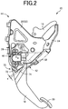
- FIG. 2 is an enlarged left side view showing only the vehicle operation pedal device 10.
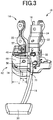
- FIG. 3 is a front view of the vehicle operation pedal device 10 as viewed from the driver's seat side.
- FIG. 4 is a perspective view of the vehicle operation pedal device 10 as viewed obliquely downward from the upper left of the driver's seat side.
- FIG. 5 is a perspective view of the vehicle operation pedal device 10 as viewed obliquely downward from the upper right of the front side of the vehicle which is the opposite side from the driver's seat.
- the vehicle operation pedal device 10 includes a pedal bracket 14 that is fixedly attached to the dash panel 12, a pedal arm 16 that is operated by being depressed with a driver's foot, and an intermediate lever 18 operatively coupled to the pedal arm 16 via a coupling link.
- An operating rod of a brake booster etc. is coupled to the intermediate lever 18.
- the pedal bracket 14 has a pair of right and left side plate members 22, 20 and a distal end coupling member 24 fixedly attached to the side plate members 20, 22 so as to couple the distal ends (on the driver's seat side) of the side plate members 20, 22.
- the pedal arm 16 is swingably supported about an axis (support axis) O of a support shaft 26 placed substantially horizontally between the side plate members 20, 22.
- the pair of side plate members 20, 22 are also fixedly coupled via a rear coupling plate 28 on the opposite side from the driver's seat, namely the dash panel 12 side.
- the support shaft 26 is a bolt disposed so as to extend through the pair of side plate members 20, 22 and the pedal arm 16 placed therebetween.
- the pedal arm 16 extends downward from the pedal bracket 14, and a pedal 30 disposed at the lower end of the pedal arm 16 is operated by being depressed with the driver's foot.
- the pedal arm 16 is returned to its initial position shown in FIGS. 1 to 6 by a return spring 32 placed so as to extend between the pedal arm 16 and the distal end coupling member 24.
- the side plate members 20, 22 function as a pair of side plates that swingably support the pedal arm 16 therebetween.
- FIGS. 7A to 7D are a four-view drawing showing only the cover member 42 as viewed in four directions.
- FIG. 7A is a front view
- FIG. 7B is a left side view
- FIG. 7C is a right side view
- FIG. 7D is a plan view.
- the front view of FIG. 7A corresponds to the front view of FIG.
- the cover member 42 is a single-piece member made of a synthetic resin material and including a lower wall portion 44 that is tilted upward toward the driver's seat so as to extend from below the stroke sensor 40 toward the driver's seat, a side wall portion 46 that is continuous with the lower wall portion 44 and disposed outside the stroke sensor 40 so as to extend upward, and an upper wall portion 48 that is continuous with the front end of the lower wall portion 44 and the side wall portion 46 and disposed above the stroke sensor 40.
- the cover member 42 thus covers the lower, lateral, and upper sides of the stroke sensor 40.
- the upper wall portion 48 has a cutout 49 through which a wire harness that is coupled to the stroke sensor 40 extends.
- An attachment wall portion 50 standing substantially vertically is provided at the rear end of the upper wall portion 48.
- Attachment holes 52, 54 are provided with the attachment wall portion 50 and a front end of the lower wall portion 44, respectively.
- the lower wall portion 44 can be attached to the side plate member 20 in a single-step operation, namely by merely inserting an insertion clip 56 (see FIG. 3 ) made of a synthetic resin through the attachment hole 54.
- the attachment wall portion 50 can be attached to the side plate member 20 by inserting a screw member 57 (see FIGS. 3 , 4 , etc.) such as a bolt, a nut, etc. through the attachment hole 52 in order to ensure predetermined attachment strength.
- the side plate member 20 has insertion holes corresponding to the attachment holes 52, 54, so that the insertion clip 56 and the bolt etc. of the screw member 57 can be inserted therethrough.
- a triangular rear wall portion 60 is provided on the rear side of the stroke sensor 40, which is the opposite side of the cover member 42 from the driver's seat, so as to couple the upper end of the side wall portion 46 to the attachment wall portion 50.
- a plurality of reinforcing ribs 62 are provided on the inner surface of a corner portion connecting the lower wall portion 44 and the side wall portion 46, and a plurality of reinforcing ribs 64 are provided on the inside of a corner portion connecting the side wall portion 46 and the upper wall portion 48 or the attachment wall portion 50.
- a reinforcing member 70 made of a metal is fixedly attached to the left side surface of the pedal arm 16 by welding etc., such that the reinforcing member 70 is interposed between the rear end of the lower wall portion 44 and the stroke sensor 40 when in an initial state where the pedal arm 16 is not operated by being depressed with the foot.
- the reinforcing member 70 is a sheet metal such as iron bent into a substantially L-shape and includes a pair of flat plate portions 72, 74.
- the reinforcing member 70 is fixedly attached to the left side surface of the pedal arm 16 such that an L-shaped side edge of the reinforcing member 70 closely contacts the left side surface of the pedal arm 16.
- FIG. 8 is a perspective view corresponding to FIG. 5 .
- the flat plate portion 74 is inserted between the lower wall portion 44 and the stroke sensor 40 in such an attitude that the flat plate portion 74 extends substantially parallel to the lower wall portion 44, so that the flat plate portion 74 is interposed between the lower wall portion 44 and the stroke sensor 40. Accordingly, when the cover member 42 is kicked with a driver's foot 76 as shown by solid lines in FIG. 1 , the lower wall portion 44 contacts the flat plate portion 74. This inhibits excessive deformation of the cover member 42 and prevents deformation and breakage of the cover member 42, whereby the stroke sensor 40 can be appropriately protected.
- the foot 76 is located in a normal position shown by chain lines in FIG.
- the foot 76 is placed on a floor 67 when it is in the normal position. However, the driver may kick the stroke sensor 40 when, for example, he/she lifts his/her foot 76 to operate the brake pedal.
- Clearance a (see FIG. 2 ) between the flat plate portion 74 and the lower wall portion 44 is decided as appropriate so that interference therebetween can be avoided when the pedal arm 16 swings, and excessive deformation of the cover member 42 can be inhibited and plastic deformation and breakage of the cover member 42 can be prevented.
- the clearance a is set to about 5 mm.
- the overlap dimension b between the cover member 42 and the flat plate portion 74 (see FIG. 3 ) is also decided as appropriate so that plastic deformation and breakage of the cover member 42 can be prevented. Since the reinforcing ribs 62 are provided in the present embodiment, the cover member 42 need only be reinforced in the range excluding the reinforcing ribs 62. For example, the overlap dimension b is about 1/3 to 1/2 of the overall width dimension c of the lower wall portion 44.
- the rear wall portion 60 is provided at the upper end of the cover member 42 and does not interfere with the reinforcing member 70.
- the cover member 42 opens wide on the rear side. However, since the cover member 42 is located near the dash panel 12, the stroke sensor 40 is not likely to be damaged by an external force applied from the rear side of the cover member 42.
- the cover member 42 is attached to the pedal bracket 14 so as to cover the stroke sensor 40 placed on the pedal bracket 14, and the reinforcing member 70 fixed to the pedal arm 16 is interposed between the lower wall portion 44 of the cover member 42 and the stroke sensor 40.
- the cover member 42 thus appropriately prevents damage to the stroke sensor 40 which is caused by kicking with the foot 76. Since the reinforcing member 70 prevents excessive deformation of the cover member 42, a synthetic resin material can be used to form a lightweight, inexpensive cover member 42. Moreover, the reinforcing member 70 need only to be provided in a minimum required range in view of the direction in which the cover member 42 is kicked etc. so that the reinforcing member 70 can prevent breakage and deformation of the cover member 42. Accordingly, a lightweight, inexpensive vehicle operation pedal device can be produced which ensures predetermined strength.
- the cover member 42 is a single-piece member made of a synthetic resin and including the side wall portion 46, the upper wall portion 48, and the rear wall portion 60 in addition to the lower wall portion 44.
- the cover member 42 thus covers the lower, lateral, upper, and upper rear sides of the stroke sensor 40.
- the stroke sensor 40 is therefore appropriately protected not only from kicking with the foot 76 but also from contact with the foot 76 by movements other than kicking and from dust, water, etc.
- the cover member 42 is made of a synthetic resin, the cover member 42 can be molded with high design flexibility. Namely, the cover member 42 can be easily molded according to various shapes of the pedal bracket 14, various locations or shapes of the stroke sensor 40, etc. so that the stroke sensor 40 can be appropriately protected.
- the stroke sensor 40 is more appropriately protected. Since the reinforcing ribs 62, 64 are provided in the corner portion connecting the lower wall portion 44 and the side wall portion 46 and the corner portion connecting the side wall portion 46 and the upper wall portion 48 or the attachment wall portion 50, rigidity of the cover member 42 is increased. Accordingly, required strength of the pedal device can be achieved, and further reduction in weight can be achieved by reduction in thickness and reduction in size of the reinforcing member 70.
- Vehicle operation pedal device 14 Pedal bracket 16: Pedal Arm 40: Stroke sensor (Operation amount sensor) 42: Cover member 44: Lower wall portion 46: Side wall portion 48: Upper wall portion 60: Rear wall portion 62: Reinforcing rib 70: Reinforcing member O: Axis (Support axis)
Landscapes
- Engineering & Computer Science (AREA)
- Transportation (AREA)
- Mechanical Engineering (AREA)
- Physics & Mathematics (AREA)
- General Physics & Mathematics (AREA)
- Automation & Control Theory (AREA)
- Chemical & Material Sciences (AREA)
- Combustion & Propulsion (AREA)
- Mechanical Control Devices (AREA)
- Braking Elements And Transmission Devices (AREA)
Claims (3)
- Dispositif de pédale de commande (10) approprié pour un véhicule comprenant un support de pédale (14) qui est fixé au véhicule, un bras de pédale (16) qui est supporté, de manière oscillante, par le support de pédale autour d'un axe de support (O) qui est horizontal en référence au véhicule, qui s'étend vers le bas à partir du support de pédale en référence au véhicule et qui a au niveau de son extrémité inférieure, une pédale (30) qui est actionnée en étant enfoncée par un pied, et un capteur de quantité d'actionnement (40) qui est disposé sur le support de pédale afin de détecter une quantité selon laquelle le bras de pédale est actionné, comprenant :un élément de recouvrement (42) qui comprend au moins une partie de paroi inférieure (44) s'étendant depuis le dessous du capteur de quantité d'actionnement vers une partie arrière du véhicule, et une partie de paroi latérale (46) qui est continue avec une partie de paroi inférieure (44) et disposée à l'extérieur du capteur de quantité d'actionnement (40) afin de s'étendre vers le haut en référence au véhicule, et qui est fixée de manière fixe sur le support de pédale ; etun élément de renforcement (70) qui est fixé, de manière fixe, au bras de pédale afin d'être intercalé entre la partie de paroi inférieure et le capteur de quantité d'actionnement lorsque, dans un état initial, dans lequel le bras de pédale n'est pas actionné en étant enfoncé avec le pied ; caractérisé en ce que :
l'élément de renforcement est réalisé à partir d'un métal ; et en ce que :
une nervure de renforcement (62) est prévue sur une surface interne d'une partie de coin raccordant la partie de paroi inférieure et la partie de paroi latérale. - Dispositif de pédale de commande selon la revendication 1, dans lequel :
l'élément de recouvrement est un élément d'un seul tenant réalisé à partir d'une résine synthétique et comprenant la partie de paroi latérale (46), et une partie de paroi supérieure (48) qui est continue avec la partie de paroi latérale et disposée au-dessus du capteur de quantité d'actionnement, et l'élément de recouvrement recouvre les côtés inférieur, latéral et supérieur du capteur de quantité d'actionnement en référence à la direction du véhicule. - Dispositif de pédale de commande selon la revendication 2, dans lequel :
l'élément de recouvrement comprend en outre une partie de paroi arrière (60) disposée sur un côté arrière du capteur de quantité d'actionnement qui est un côté opposé à l'arrière du véhicule, afin de ne pas gêner le mouvement de l'élément de renforcement qui est associé à l'oscillation du bras de pédale.
Applications Claiming Priority (2)
| Application Number | Priority Date | Filing Date | Title |
|---|---|---|---|
| JP2013227905A JP6068751B2 (ja) | 2013-11-01 | 2013-11-01 | 車両用操作ペダル装置 |
| PCT/JP2014/068831 WO2015064156A1 (fr) | 2013-11-01 | 2014-07-15 | Dispositif de pédale de commande pour véhicule |
Publications (3)
| Publication Number | Publication Date |
|---|---|
| EP3065023A1 EP3065023A1 (fr) | 2016-09-07 |
| EP3065023A4 EP3065023A4 (fr) | 2017-05-31 |
| EP3065023B1 true EP3065023B1 (fr) | 2019-11-06 |
Family
ID=53003775
Family Applications (1)
| Application Number | Title | Priority Date | Filing Date |
|---|---|---|---|
| EP14858166.3A Active EP3065023B1 (fr) | 2013-11-01 | 2014-07-15 | Dispositif de pédale de commande pour véhicule |
Country Status (5)
| Country | Link |
|---|---|
| US (1) | US10067526B2 (fr) |
| EP (1) | EP3065023B1 (fr) |
| JP (1) | JP6068751B2 (fr) |
| CN (1) | CN105659183B (fr) |
| WO (1) | WO2015064156A1 (fr) |
Families Citing this family (6)
| Publication number | Priority date | Publication date | Assignee | Title |
|---|---|---|---|---|
| US9676375B2 (en) * | 2014-08-28 | 2017-06-13 | Mazda Motor Corporation | Pedal stroke sensor attachment structure of automotive vehicle |
| JP6839415B2 (ja) * | 2017-03-14 | 2021-03-10 | いすゞ自動車株式会社 | ペダル上方のプロテクタ |
| CN107132873A (zh) * | 2017-06-09 | 2017-09-05 | 浙江泰鸿机电有限公司 | 带弹簧防脱及开关防失效保护的脚踏板总成 |
| JP7443187B2 (ja) * | 2020-08-05 | 2024-03-05 | 豊田鉄工株式会社 | 車両用操作ペダル装置 |
| JP7354066B2 (ja) * | 2020-08-05 | 2023-10-02 | 豊田鉄工株式会社 | 車両用操作ペダル装置における操作量センサ取付構造 |
| JP7743385B2 (ja) * | 2022-10-25 | 2025-09-24 | 豊田鉄工株式会社 | 車両用操作ペダル装置 |
Family Cites Families (18)
| Publication number | Priority date | Publication date | Assignee | Title |
|---|---|---|---|---|
| US6220222B1 (en) * | 1999-05-18 | 2001-04-24 | Teleflex Incorporated | Electronic control assembly for a pedal |
| JP2004009821A (ja) * | 2002-06-05 | 2004-01-15 | Aisan Ind Co Ltd | アクセル装置 |
| US20060117902A1 (en) * | 2004-11-29 | 2006-06-08 | Tom Martin | Pedal assembly with an integrated non-contact rotational position sensor |
| JP2006290082A (ja) * | 2005-04-07 | 2006-10-26 | Aisan Ind Co Ltd | アクセルペダルモジュール |
| JP5153651B2 (ja) * | 2006-02-02 | 2013-02-27 | シーティーエス・コーポレーション | 乗物用アクセルペダル |
| DE202006010840U1 (de) * | 2006-05-23 | 2006-09-14 | Ab Elektronik Gmbh | Fahrpedalvorrichtung |
| US8069750B2 (en) | 2007-08-09 | 2011-12-06 | Ksr Technologies Co. | Compact pedal assembly with improved noise control |
| CN201566601U (zh) * | 2009-11-11 | 2010-09-01 | 浙江吉利汽车研究院有限公司 | 电子制动踏板 |
| JP2011164897A (ja) * | 2010-02-09 | 2011-08-25 | Berusonika:Kk | 車両用ペダルアーム |
| JP5327155B2 (ja) * | 2010-07-15 | 2013-10-30 | 株式会社デンソー | ペダル装置 |
| JP5257797B2 (ja) | 2010-09-14 | 2013-08-07 | 株式会社デンソー | アクセル装置 |
| JP2012240565A (ja) * | 2011-05-20 | 2012-12-10 | Denso Corp | アクセル装置 |
| JP5282919B2 (ja) * | 2011-05-25 | 2013-09-04 | 株式会社デンソー | アクセル装置 |
| JP5714426B2 (ja) | 2011-06-23 | 2015-05-07 | 本田技研工業株式会社 | ブレーキペダル装置 |
| JP5866848B2 (ja) | 2011-08-02 | 2016-02-24 | マツダ株式会社 | 車両の制動装置 |
| JP5743789B2 (ja) * | 2011-08-02 | 2015-07-01 | 株式会社ミクニ | アクセルペダル装置 |
| US9739639B2 (en) * | 2013-07-10 | 2017-08-22 | Panasonic Intellectual Property Management Co., Ltd. | Rotation angle detection device |
| US9632525B2 (en) * | 2013-09-27 | 2017-04-25 | Cts Corporation | Shaftless vehicle pedal with contacting position sensor |
-
2013
- 2013-11-01 JP JP2013227905A patent/JP6068751B2/ja active Active
-
2014
- 2014-07-15 CN CN201480057983.0A patent/CN105659183B/zh active Active
- 2014-07-15 EP EP14858166.3A patent/EP3065023B1/fr active Active
- 2014-07-15 US US15/031,336 patent/US10067526B2/en active Active
- 2014-07-15 WO PCT/JP2014/068831 patent/WO2015064156A1/fr not_active Ceased
Non-Patent Citations (1)
| Title |
|---|
| None * |
Also Published As
| Publication number | Publication date |
|---|---|
| WO2015064156A1 (fr) | 2015-05-07 |
| JP2015088082A (ja) | 2015-05-07 |
| EP3065023A1 (fr) | 2016-09-07 |
| EP3065023A4 (fr) | 2017-05-31 |
| US10067526B2 (en) | 2018-09-04 |
| CN105659183B (zh) | 2018-12-14 |
| US20160259361A1 (en) | 2016-09-08 |
| CN105659183A (zh) | 2016-06-08 |
| JP6068751B2 (ja) | 2017-01-25 |
Similar Documents
| Publication | Publication Date | Title |
|---|---|---|
| EP3065023B1 (fr) | Dispositif de pédale de commande pour véhicule | |
| US8016347B2 (en) | Front structure of automobile hood | |
| US7497144B2 (en) | Brake pedal structure | |
| US8337064B2 (en) | Lamp mounting structure and vehicle to which lamp is mounted with the use of the same | |
| JP4696216B2 (ja) | ペダル装置 | |
| US20070000708A1 (en) | Vehicle-pedal backward-displacement preventing device | |
| US20150329089A1 (en) | Vehicle pedal device | |
| CN105365795B (zh) | 车辆用踏板臂 | |
| JP2011073635A (ja) | 車両用電子制御装置の取付構造 | |
| JP2015003595A (ja) | 乗物用シート | |
| JP5685470B2 (ja) | 車両用操作ペダル構造 | |
| US11092992B2 (en) | Vehicle pedal device | |
| JP4613001B2 (ja) | ペダルモジュール | |
| JP5915933B2 (ja) | 車両用ブレーキ装置 | |
| JP7207263B2 (ja) | オルガン式ペダルを備えた車両用フロア構造 | |
| WO2015040874A1 (fr) | Pédale d'actionnement de véhicule | |
| JP6555003B2 (ja) | フェンダー構造 | |
| JP7443187B2 (ja) | 車両用操作ペダル装置 | |
| JP7501692B1 (ja) | 車両フロント構造 | |
| JP5832011B2 (ja) | 車両用フットレスト | |
| JP6048360B2 (ja) | 車両用ペダル装置 | |
| JP2018118668A (ja) | センターコンソール構造 | |
| JP2018184111A (ja) | 運転室構造 | |
| JP4937096B2 (ja) | 産業用車両におけるパーキングブレーキ装置 | |
| JP2015048052A (ja) | ペダル装置の取付構造 |
Legal Events
| Date | Code | Title | Description |
|---|---|---|---|
| PUAI | Public reference made under article 153(3) epc to a published international application that has entered the european phase |
Free format text: ORIGINAL CODE: 0009012 |
|
| 17P | Request for examination filed |
Effective date: 20160510 |
|
| AK | Designated contracting states |
Kind code of ref document: A1 Designated state(s): AL AT BE BG CH CY CZ DE DK EE ES FI FR GB GR HR HU IE IS IT LI LT LU LV MC MK MT NL NO PL PT RO RS SE SI SK SM TR |
|
| AX | Request for extension of the european patent |
Extension state: BA ME |
|
| DAX | Request for extension of the european patent (deleted) | ||
| A4 | Supplementary search report drawn up and despatched |
Effective date: 20170504 |
|
| RIC1 | Information provided on ipc code assigned before grant |
Ipc: B60K 26/02 20060101ALI20170426BHEP Ipc: G05G 25/00 20060101ALI20170426BHEP Ipc: G05G 1/30 20080401AFI20170426BHEP Ipc: B60T 7/06 20060101ALI20170426BHEP |
|
| REG | Reference to a national code |
Ref country code: DE Ref legal event code: R079 Ref document number: 602014056535 Country of ref document: DE Free format text: PREVIOUS MAIN CLASS: G05G0001300000 Ipc: B60K0026040000 |
|
| RIC1 | Information provided on ipc code assigned before grant |
Ipc: B60K 26/02 20060101ALI20190411BHEP Ipc: B60K 26/04 20060101AFI20190411BHEP |
|
| GRAP | Despatch of communication of intention to grant a patent |
Free format text: ORIGINAL CODE: EPIDOSNIGR1 |
|
| STAA | Information on the status of an ep patent application or granted ep patent |
Free format text: STATUS: GRANT OF PATENT IS INTENDED |
|
| INTG | Intention to grant announced |
Effective date: 20190520 |
|
| GRAS | Grant fee paid |
Free format text: ORIGINAL CODE: EPIDOSNIGR3 |
|
| GRAA | (expected) grant |
Free format text: ORIGINAL CODE: 0009210 |
|
| STAA | Information on the status of an ep patent application or granted ep patent |
Free format text: STATUS: THE PATENT HAS BEEN GRANTED |
|
| AK | Designated contracting states |
Kind code of ref document: B1 Designated state(s): AL AT BE BG CH CY CZ DE DK EE ES FI FR GB GR HR HU IE IS IT LI LT LU LV MC MK MT NL NO PL PT RO RS SE SI SK SM TR |
|
| REG | Reference to a national code |
Ref country code: GB Ref legal event code: FG4D |
|
| REG | Reference to a national code |
Ref country code: CH Ref legal event code: EP Ref country code: AT Ref legal event code: REF Ref document number: 1198278 Country of ref document: AT Kind code of ref document: T Effective date: 20191115 |
|
| REG | Reference to a national code |
Ref country code: DE Ref legal event code: R096 Ref document number: 602014056535 Country of ref document: DE |
|
| REG | Reference to a national code |
Ref country code: IE Ref legal event code: FG4D |
|
| REG | Reference to a national code |
Ref country code: NL Ref legal event code: MP Effective date: 20191106 |
|
| REG | Reference to a national code |
Ref country code: LT Ref legal event code: MG4D |
|
| PG25 | Lapsed in a contracting state [announced via postgrant information from national office to epo] |
Ref country code: PT Free format text: LAPSE BECAUSE OF FAILURE TO SUBMIT A TRANSLATION OF THE DESCRIPTION OR TO PAY THE FEE WITHIN THE PRESCRIBED TIME-LIMIT Effective date: 20200306 Ref country code: SE Free format text: LAPSE BECAUSE OF FAILURE TO SUBMIT A TRANSLATION OF THE DESCRIPTION OR TO PAY THE FEE WITHIN THE PRESCRIBED TIME-LIMIT Effective date: 20191106 Ref country code: LV Free format text: LAPSE BECAUSE OF FAILURE TO SUBMIT A TRANSLATION OF THE DESCRIPTION OR TO PAY THE FEE WITHIN THE PRESCRIBED TIME-LIMIT Effective date: 20191106 Ref country code: FI Free format text: LAPSE BECAUSE OF FAILURE TO SUBMIT A TRANSLATION OF THE DESCRIPTION OR TO PAY THE FEE WITHIN THE PRESCRIBED TIME-LIMIT Effective date: 20191106 Ref country code: BG Free format text: LAPSE BECAUSE OF FAILURE TO SUBMIT A TRANSLATION OF THE DESCRIPTION OR TO PAY THE FEE WITHIN THE PRESCRIBED TIME-LIMIT Effective date: 20200206 Ref country code: GR Free format text: LAPSE BECAUSE OF FAILURE TO SUBMIT A TRANSLATION OF THE DESCRIPTION OR TO PAY THE FEE WITHIN THE PRESCRIBED TIME-LIMIT Effective date: 20200207 Ref country code: NO Free format text: LAPSE BECAUSE OF FAILURE TO SUBMIT A TRANSLATION OF THE DESCRIPTION OR TO PAY THE FEE WITHIN THE PRESCRIBED TIME-LIMIT Effective date: 20200206 Ref country code: PL Free format text: LAPSE BECAUSE OF FAILURE TO SUBMIT A TRANSLATION OF THE DESCRIPTION OR TO PAY THE FEE WITHIN THE PRESCRIBED TIME-LIMIT Effective date: 20191106 Ref country code: NL Free format text: LAPSE BECAUSE OF FAILURE TO SUBMIT A TRANSLATION OF THE DESCRIPTION OR TO PAY THE FEE WITHIN THE PRESCRIBED TIME-LIMIT Effective date: 20191106 Ref country code: LT Free format text: LAPSE BECAUSE OF FAILURE TO SUBMIT A TRANSLATION OF THE DESCRIPTION OR TO PAY THE FEE WITHIN THE PRESCRIBED TIME-LIMIT Effective date: 20191106 |
|
| PG25 | Lapsed in a contracting state [announced via postgrant information from national office to epo] |
Ref country code: HR Free format text: LAPSE BECAUSE OF FAILURE TO SUBMIT A TRANSLATION OF THE DESCRIPTION OR TO PAY THE FEE WITHIN THE PRESCRIBED TIME-LIMIT Effective date: 20191106 Ref country code: IS Free format text: LAPSE BECAUSE OF FAILURE TO SUBMIT A TRANSLATION OF THE DESCRIPTION OR TO PAY THE FEE WITHIN THE PRESCRIBED TIME-LIMIT Effective date: 20200306 Ref country code: RS Free format text: LAPSE BECAUSE OF FAILURE TO SUBMIT A TRANSLATION OF THE DESCRIPTION OR TO PAY THE FEE WITHIN THE PRESCRIBED TIME-LIMIT Effective date: 20191106 |
|
| PG25 | Lapsed in a contracting state [announced via postgrant information from national office to epo] |
Ref country code: AL Free format text: LAPSE BECAUSE OF FAILURE TO SUBMIT A TRANSLATION OF THE DESCRIPTION OR TO PAY THE FEE WITHIN THE PRESCRIBED TIME-LIMIT Effective date: 20191106 |
|
| PG25 | Lapsed in a contracting state [announced via postgrant information from national office to epo] |
Ref country code: EE Free format text: LAPSE BECAUSE OF FAILURE TO SUBMIT A TRANSLATION OF THE DESCRIPTION OR TO PAY THE FEE WITHIN THE PRESCRIBED TIME-LIMIT Effective date: 20191106 Ref country code: RO Free format text: LAPSE BECAUSE OF FAILURE TO SUBMIT A TRANSLATION OF THE DESCRIPTION OR TO PAY THE FEE WITHIN THE PRESCRIBED TIME-LIMIT Effective date: 20191106 Ref country code: CZ Free format text: LAPSE BECAUSE OF FAILURE TO SUBMIT A TRANSLATION OF THE DESCRIPTION OR TO PAY THE FEE WITHIN THE PRESCRIBED TIME-LIMIT Effective date: 20191106 Ref country code: ES Free format text: LAPSE BECAUSE OF FAILURE TO SUBMIT A TRANSLATION OF THE DESCRIPTION OR TO PAY THE FEE WITHIN THE PRESCRIBED TIME-LIMIT Effective date: 20191106 Ref country code: DK Free format text: LAPSE BECAUSE OF FAILURE TO SUBMIT A TRANSLATION OF THE DESCRIPTION OR TO PAY THE FEE WITHIN THE PRESCRIBED TIME-LIMIT Effective date: 20191106 |
|
| REG | Reference to a national code |
Ref country code: DE Ref legal event code: R097 Ref document number: 602014056535 Country of ref document: DE |
|
| REG | Reference to a national code |
Ref country code: AT Ref legal event code: MK05 Ref document number: 1198278 Country of ref document: AT Kind code of ref document: T Effective date: 20191106 |
|
| PG25 | Lapsed in a contracting state [announced via postgrant information from national office to epo] |
Ref country code: SM Free format text: LAPSE BECAUSE OF FAILURE TO SUBMIT A TRANSLATION OF THE DESCRIPTION OR TO PAY THE FEE WITHIN THE PRESCRIBED TIME-LIMIT Effective date: 20191106 Ref country code: SK Free format text: LAPSE BECAUSE OF FAILURE TO SUBMIT A TRANSLATION OF THE DESCRIPTION OR TO PAY THE FEE WITHIN THE PRESCRIBED TIME-LIMIT Effective date: 20191106 |
|
| PLBE | No opposition filed within time limit |
Free format text: ORIGINAL CODE: 0009261 |
|
| STAA | Information on the status of an ep patent application or granted ep patent |
Free format text: STATUS: NO OPPOSITION FILED WITHIN TIME LIMIT |
|
| 26N | No opposition filed |
Effective date: 20200807 |
|
| PG25 | Lapsed in a contracting state [announced via postgrant information from national office to epo] |
Ref country code: SI Free format text: LAPSE BECAUSE OF FAILURE TO SUBMIT A TRANSLATION OF THE DESCRIPTION OR TO PAY THE FEE WITHIN THE PRESCRIBED TIME-LIMIT Effective date: 20191106 Ref country code: AT Free format text: LAPSE BECAUSE OF FAILURE TO SUBMIT A TRANSLATION OF THE DESCRIPTION OR TO PAY THE FEE WITHIN THE PRESCRIBED TIME-LIMIT Effective date: 20191106 |
|
| PG25 | Lapsed in a contracting state [announced via postgrant information from national office to epo] |
Ref country code: IT Free format text: LAPSE BECAUSE OF FAILURE TO SUBMIT A TRANSLATION OF THE DESCRIPTION OR TO PAY THE FEE WITHIN THE PRESCRIBED TIME-LIMIT Effective date: 20191106 |
|
| PG25 | Lapsed in a contracting state [announced via postgrant information from national office to epo] |
Ref country code: MC Free format text: LAPSE BECAUSE OF FAILURE TO SUBMIT A TRANSLATION OF THE DESCRIPTION OR TO PAY THE FEE WITHIN THE PRESCRIBED TIME-LIMIT Effective date: 20191106 |
|
| REG | Reference to a national code |
Ref country code: CH Ref legal event code: PL |
|
| REG | Reference to a national code |
Ref country code: BE Ref legal event code: MM Effective date: 20200731 |
|
| PG25 | Lapsed in a contracting state [announced via postgrant information from national office to epo] |
Ref country code: CH Free format text: LAPSE BECAUSE OF NON-PAYMENT OF DUE FEES Effective date: 20200731 Ref country code: LI Free format text: LAPSE BECAUSE OF NON-PAYMENT OF DUE FEES Effective date: 20200731 Ref country code: LU Free format text: LAPSE BECAUSE OF NON-PAYMENT OF DUE FEES Effective date: 20200715 |
|
| PG25 | Lapsed in a contracting state [announced via postgrant information from national office to epo] |
Ref country code: BE Free format text: LAPSE BECAUSE OF NON-PAYMENT OF DUE FEES Effective date: 20200731 |
|
| PG25 | Lapsed in a contracting state [announced via postgrant information from national office to epo] |
Ref country code: IE Free format text: LAPSE BECAUSE OF NON-PAYMENT OF DUE FEES Effective date: 20200715 |
|
| PG25 | Lapsed in a contracting state [announced via postgrant information from national office to epo] |
Ref country code: TR Free format text: LAPSE BECAUSE OF FAILURE TO SUBMIT A TRANSLATION OF THE DESCRIPTION OR TO PAY THE FEE WITHIN THE PRESCRIBED TIME-LIMIT Effective date: 20191106 Ref country code: MT Free format text: LAPSE BECAUSE OF FAILURE TO SUBMIT A TRANSLATION OF THE DESCRIPTION OR TO PAY THE FEE WITHIN THE PRESCRIBED TIME-LIMIT Effective date: 20191106 Ref country code: CY Free format text: LAPSE BECAUSE OF FAILURE TO SUBMIT A TRANSLATION OF THE DESCRIPTION OR TO PAY THE FEE WITHIN THE PRESCRIBED TIME-LIMIT Effective date: 20191106 |
|
| PG25 | Lapsed in a contracting state [announced via postgrant information from national office to epo] |
Ref country code: MK Free format text: LAPSE BECAUSE OF FAILURE TO SUBMIT A TRANSLATION OF THE DESCRIPTION OR TO PAY THE FEE WITHIN THE PRESCRIBED TIME-LIMIT Effective date: 20191106 |
|
| PGFP | Annual fee paid to national office [announced via postgrant information from national office to epo] |
Ref country code: GB Payment date: 20240530 Year of fee payment: 11 |
|
| PGFP | Annual fee paid to national office [announced via postgrant information from national office to epo] |
Ref country code: FR Payment date: 20240611 Year of fee payment: 11 |
|
| PGFP | Annual fee paid to national office [announced via postgrant information from national office to epo] |
Ref country code: DE Payment date: 20240529 Year of fee payment: 11 |
|
| REG | Reference to a national code |
Ref country code: DE Ref legal event code: R119 Ref document number: 602014056535 Country of ref document: DE |
|
| GBPC | Gb: european patent ceased through non-payment of renewal fee |
Effective date: 20250715 |
|
| PG25 | Lapsed in a contracting state [announced via postgrant information from national office to epo] |
Ref country code: GB Free format text: LAPSE BECAUSE OF NON-PAYMENT OF DUE FEES Effective date: 20250715 |
|
| PG25 | Lapsed in a contracting state [announced via postgrant information from national office to epo] |
Ref country code: DE Free format text: LAPSE BECAUSE OF NON-PAYMENT OF DUE FEES Effective date: 20260203 |
|
| PG25 | Lapsed in a contracting state [announced via postgrant information from national office to epo] |
Ref country code: FR Free format text: LAPSE BECAUSE OF NON-PAYMENT OF DUE FEES Effective date: 20250731 |