EP3065108A1 - Affichage d'une visite virtuelle - Google Patents
Affichage d'une visite virtuelle Download PDFInfo
- Publication number
- EP3065108A1 EP3065108A1 EP16158769.6A EP16158769A EP3065108A1 EP 3065108 A1 EP3065108 A1 EP 3065108A1 EP 16158769 A EP16158769 A EP 16158769A EP 3065108 A1 EP3065108 A1 EP 3065108A1
- Authority
- EP
- European Patent Office
- Prior art keywords
- image
- point
- images
- virtual tour
- displayed
- Prior art date
- Legal status (The legal status is an assumption and is not a legal conclusion. Google has not performed a legal analysis and makes no representation as to the accuracy of the status listed.)
- Ceased
Links
Images








Classifications
-
- G—PHYSICS
- G06—COMPUTING OR CALCULATING; COUNTING
- G06T—IMAGE DATA PROCESSING OR GENERATION, IN GENERAL
- G06T19/00—Manipulating three-dimensional [3D] models or images for computer graphics
- G06T19/003—Navigation within 3D models or images
-
- G—PHYSICS
- G06—COMPUTING OR CALCULATING; COUNTING
- G06T—IMAGE DATA PROCESSING OR GENERATION, IN GENERAL
- G06T15/00—Three-dimensional [3D] image rendering
- G06T15/10—Geometric effects
- G06T15/20—Perspective computation
- G06T15/205—Image-based rendering
-
- G—PHYSICS
- G06—COMPUTING OR CALCULATING; COUNTING
- G06T—IMAGE DATA PROCESSING OR GENERATION, IN GENERAL
- G06T7/00—Image analysis
- G06T7/30—Determination of transform parameters for the alignment of images, i.e. image registration
- G06T7/33—Determination of transform parameters for the alignment of images, i.e. image registration using feature-based methods
-
- G—PHYSICS
- G06—COMPUTING OR CALCULATING; COUNTING
- G06T—IMAGE DATA PROCESSING OR GENERATION, IN GENERAL
- G06T7/00—Image analysis
- G06T7/70—Determining position or orientation of objects or cameras
- G06T7/73—Determining position or orientation of objects or cameras using feature-based methods
-
- G—PHYSICS
- G06—COMPUTING OR CALCULATING; COUNTING
- G06T—IMAGE DATA PROCESSING OR GENERATION, IN GENERAL
- G06T2210/00—Indexing scheme for image generation or computer graphics
- G06T2210/36—Level of detail
Definitions
- This disclosure generally relates to a virtual tour.
- Virtual tour provides an immersive three-dimensional experience for a user so that the user may travel freely through the virtual tour.
- a perspective of a virtual camera changes, as the virtual camera moves forward and backward or turns around in the virtual tour.
- Users may control the movement, orientation, and lens focal length of the virtual camera so the users may freely travel in the virtual tour.
- virtual tour may be generated by stitching together a number of images captured in the real world. Stitched images may be shown as a single panoramic image to user. However, the single panoramic image only presents visual representation of a scene at a fixed point, so user experience may be limited in the virtual tour.
- a virtual tour application or player provides a virtual environment in which a user can travel.
- One or more images may be displayed in the virtual tour application or player.
- the images are blended with each other to enable a user to feel more natural while he or she traveling in the virtual tour.
- Displaying a virtual tour in an electronic device is provided.
- a first image which corresponds to a first point included among a plurality of points along a route in a virtual tour is displayed.
- a second image which is registered with the first image and corresponds to a second point included among the plurality of points and different from the first point is displayed.
- aspects of this disclosure provide computer-readable instructions, methods, user interface displays, and an electronic device for displaying a virtual tour.
- a first image which corresponds to a first point included among a plurality of points along a route in a virtual tour is displayed.
- a second image which is registered with the first image and corresponds to a second point different from the first point included among the plurality of points is displayed.
- FIG. 1 is a block diagram of an exemplary electronic device for displaying virtual tour, according to an embodiment.
- the electronic device 100 may be, for example but not limited to a laptop, a desktop computer, a mobile phone, a smart phone, Personal Digital Assistants (PDAs), a tablet, a smart watch, a phablet, a consumer electronic device, or any other electronic device.
- PDAs Personal Digital Assistants
- the electronic device 100 includes a display 104, a processor 106, and storage 110.
- the display 104 may be configured to display a virtual tour including one or more images.
- the images may be a sequence of images, frames of a video, or a combination thereof.
- the images may be blended with each other to represent scenes in the virtual tour.
- Each of the images may correspond to a point where the each of the images is captured.
- the point may be in the form of X and Y coordinates.
- the point may be in the form of X, Y, and Z coordinates.
- points on which images are captured may compose a route in the virtual tour.
- the route may be generated based on the points, and the route may be displayed in the virtual tour.
- the route may be displayed in a map.
- images corresponding to a same point along the route may be stitched with each other to compose a single panoramic image.
- the images corresponding to a same point along the route may be included in a set of turn images.
- images corresponding to different points along the route may be registered with each other.
- the images corresponding to different points along the route may be included in a set of images.
- the virtual tour is rendered by blending a sequence of images.
- the sequence of images may include a set of images which are captured while a camera capturing the set of images moves forward or backward, and turn images which are captured while the camera capturing the turn images turns around at a certain location.
- the set of images may correspond to different points along the route.
- the processor 106 may be configured to control display 104 to display blended images, and the blended image may be displayed continuously, so a user may be provided with an improved user experience while navigating the virtual tour.
- the processor 106 may be configured to control components of the electronic device 100 to perform one or more operations for navigating a virtual tour.
- the processor 106 may be configured to control the display 104 to display the virtual tour.
- the processor 106 may be configured to control the display 104 to display a first image corresponding to a first point included among a plurality of points along a route in the virtual tour.
- the processor 106 may be configured to control the display 104 to display a second image corresponding to a second point included among the plurality of points along the route.
- the first image may be a currently displayed image in the virtual tour
- the first point may be a starting point from which a user moves in the virtual tour or the current location of the user in the virtual tour.
- the second point may be a destination point to which the user moves in the virtual tour
- the second image may be an image destined to be displayed as the user arrives at the destination point in the virtual tour.
- the first image and the second image may be registered with each other.
- the processor 106 may be configured to control the display 104 to display the second image in the virtual tour. In particular embodiments, the processor 106 may be configured to control the display 104 to display the second image in response to an input.
- the input may be received by an input interface of the electronic device 100, or sensed by a sensor or the electronic device 100, so the second image may be displayed in response to the input such as a touch input, or tilting or shaking of the electronic device 100.
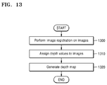
- FIG. 13 illustrates an exemplary method for generating a depth map using image registration, according to an embodiment.
- FIG. 14 illustrates an exemplary generating of a depth map using image registration, according to an embodiment.
- the sequence of operations may be performed by the processor 106 of the electronic device 100 or pre-performed by another electronic device.
- image registration may be performed on images I1-I8 as shown Fig. 14 .
- the images 11-18 may be a set of images, which were captured while a camera capturing the set of the images was moving forward.
- the image I1 may be a base image which is captured earlier than other images I2-I8.
- the image I2 comes after the image I1.
- the image I1 includes a part overlapped with the image I2, since the images I1-I8 were captured while the camera capturing the images I1-I8 was moving forward.
- the images 11-18 may be registered based on optical flow of the images I1-I8.
- the images 11-18 may be registered in order of capture time of the images I1-I8.
- the images 11-18 may be registered in reverse order of capture time of the images I1-I8.
- the image I1 may be registered with the image I2, and a size of the registered image D2 in the registered image D1 may be determined based on locations where the images I1 and I2 are captured.
- the size of the registered image D2 in the registered image D1 may be determined based on distance between locations where the images I1 and I2 are captured.
- a location of the registered image D2 in the registered image D1 may be determined based on orientation angles of the images I1 and I2 with respect to a reference point, and the reference point may be a point of the image I1 or a point of the image 12.
- the location of the registered image D2 in the registered image D1 may be determined based on a difference between orientation angles of the images I1 and 12.
- the image I1 and the image I2 may be registered with each other based on sides of the image I1 and the image I2, and the sides of the image I1 and the image I2 are oriented toward the same direction. For example, an upper-side of the image I1 and an upper-side of the image I2 may be registered with each other.
- depth values may be assigned to the images I1-I8 or the registered images D1-D8.
- the lowest depth value may be assigned to the image I1 or the registered image D1.
- the lowest depth value may be assigned to borders of the image I1 or the registered image D1.
- the lowest depth value may be assigned to a part not overlapped with the image I2 or the registered image D2.
- the highest depth value may be assigned to the image I8 or the registered image D8.
- a depth map M1 may be generated based on depth values assigned to the images 11-18 or the registered images D1-D8. Depth values may be assigned to parts not overlapped with following images.
- one or more depth values may be assigned to the each of the images 11-18 or the each of the images D1-D8.
- the lowest depth value may be assigned to borders of the image I1 or the registered image D1
- the second lowest depth value may be assigned to a part not overlapped with the image I2 or the registered image D2.
- One or more depth values assigned to the image I2 or the registered image D2 may be higher than ones assigned to the image I1 or the registered image D1.
- the storage 110 may store images, and the images may include a set of images and turn images. The set of images and the turn images may be pre-stored. Further, the storage 110 may include one or more computer-readable storage media.
- the storage 110 may include non-volatile storage elements. Examples of such non-volatile storage elements may include magnetic hard discs, optical discs, floppy discs, flash memories, or forms of electrically programmable memories (EPROM) or electrically erasable and programmable (EEPROM) memories.
- EPROM electrically programmable memories
- EEPROM electrically erasable and programmable
- the display 104 may be configured to display at least one indicator in the virtual tour.
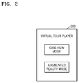
- FIG. 2 illustrates an exemplary virtual tour player 200, according to an embodiment.
- the storage 110 may store a virtual tour player 200, and the processor 106 may control the virtual tour player 200 to display a virtual tour.
- the storage 110 may store images and corresponding metadata for the images.
- the metadata may include information obtained during capture of the images, such as, time information, location information, orientation angle information, rotation information, acceleration information, velocity information, speed information, height information, or inclination information of the images.
- the information may be obtained by a Global Positioning System, a gyroscope, an accelerometer, a barometer or a combination thereof.
- an accelerometer may be used to ascertain a gravity vector and alignment factor for the images.
- parallax of the images may be adjusted based on the relative positions of the images.
- the virtual tour player 200 may operate in a grid view mode, an augmented reality mode, or a combination thereof.
- the virtual tour player 200 may have features of play, pause, stop, fast forward, rewind, and seek of a virtual tour.
- images may be displayed according to order of corresponding points in a route.
- the virtual tour is fast forward, paused or stopped
- the play of the virtual tour is fast forwarded, paused or stopped.
- the images may be displayed in a reverse order from a currently displayed image.
- a progress bar may be displayed in the virtual tour player 200, the seeking of the virtual tour may be performed with aid of the progress bar.
- FIG. 3 illustrates an exemplary method for displaying an exemplary virtual tour, according to an embodiment.
- a first image corresponding to a first point included among a plurality of points along a route may be displayed in a virtual tour.
- a map may be displayed with the first image and the route may be displayed in the map. The map may be hidden according to user's selection.
- an input may be received.
- the input may be an input to select a second point included among the plurality of points along the route.
- the input may be received by tilting or shaking an electronic device displaying the virtual tour.
- the input may be received by playing the virtual tour.
- a second image registered with the first image and corresponding to a second point may be displayed in the virtual tour.
- the second image may be registered with another image registered with the first image, such that the second image may be registered with the first image.
- the second image and the first image may be a set of images.
- a virtual tour is rendered by blending a sequence of images based on a depth map.
- a transition effect may be generated based on the depth map. The transition effect may occur while a user in the virtual tour moves from a first point to a second point. In other words, the transition effect may occur while an image displayed in the virtual tour is changed from a first image to a second image.
- the first image may be a currently displayed image in the virtual tour
- the first point may be a starting point from which a user moves in the virtual tour or the current location of the user in the virtual tour.
- the second point may be a destination point to which the user moves in the virtual tour
- the second image may be an image destined to be displayed as the user arrives at the destination point in the virtual tour.
- the first image and the second image may be registered with each other.
- depth values of a set of images in a depth map are determined based on distances between points of the set of images.
- the distances between the points of the set of images may be determined according to an image analysis of the set of images.
- the image analysis may be based on optical flow of the set of images, or focus of attention and focus of expansion between the set of images.
- the distance between the points of the set of images may be determined based on information sensed during capture of the set of images. The sensed information may be used to count steps taken between locations where the set of images are captured, and the distance between the points of the set of images may be determined based on the number of steps.
- the depth map may be generated using image registration.
- the depth map may be generated using alignment factor, or calibration data of the set of images.
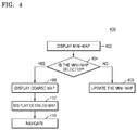
- FIG. 4 illustrates an exemplary method 400 for displaying an exemplary multi-level maps, according to an embodiment.
- FIGs. 7A-7C illustrate exemplary maps in a virtual tour, according to an embodiment.
- a virtual tour 700 may be displayed in the grid view mode.
- a mini-map 720 may be displayed in the virtual tour 700 of the grid view mode.
- a route 722 may be displayed in the mini-map 720. The route 722 may allow a user know where the user is located in the virtual tour.
- the mini-map 720 may be updated.
- the mini-map 720 may be updated according to the current location 724 of the user in the virtual tour 700 or a direction to which the user is oriented in the virtual tour 700.
- a coarse map 730 may be displayed.
- the coarse map 730 may be more detailed than the mini-map 720, and at least one indicator may be displayed in the coarse map 730.
- indicators may be represented as thumbnails 736 corresponding to images.
- a plurality of thumbnails 736a, 736b, 736c, 736d, and 736e may be displayed in the coarse map 730.
- the arrangement of the thumbnails 736 may correspond to the points along the route 732, and the thumbnails 736 may be displayed along the route 732 in the coarse map 730.
- the distance between thumbnails 736 may correspond to a distance between the points.
- the mini-map 720 may be selected based on an input, and the input may be received by an input interface of the electronic device, or sensed by a sensor or the electronic device, so the coarse map may 730 be displayed in response to the input such as a touch input P1, or tilting or shaking of the electronic device.
- a detailed map 740 may be displayed in the virtual tour 700.
- the detailed map 740 may be more detailed than the mini-map 720 or the coarse map 730, and at least one indicator may be displayed in the detailed map 740.
- Indicator may be represented as thumbnails 746 corresponding to images, and a plurality of thumbnails 746a, 746b, 746c, 746d, 746e, 746f, 746g, and 746h may be displayed in the detailed map 740.
- more thumbnails may be displayed in the detailed map 740 than the coarse map 730.
- priorities of indicators may be determined based on significance of corresponding images.
- An electronic device may determine, based on priorities of indicators and a level of a map, which indicators are displayed in the map. As an example and not by way of limitation, certain indicators having the same priority may be displayed in the map which has a certain detail level, while other indicators having lower priorities than the indicators having the same priority are not displayed in the map.
- an image captured at a corner or including a corner therein may be more significant than other images.
- an image where colors or brightness changes significantly compared to previous or next images. Order of the images may be determined by order of points in the route or order of capture time of the images.
- thumbnail 746d, 746e, 746f, 746g, or 746h having a certain priority may not be displayed in the coarse map 730, and the thumbnail 746d, 746e, 746f, 746g, or 746h may be displayed in the detailed map 740.
- thumbnails 736a, 736b, 736c displayed in the coarse map 730 may have higher priorities than thumbnails 746 displayed in the detailed map 740.
- the coarse map 730 and the detail map 740 may be displayed together.
- a detail level of a map 720, 730, or 740 may change by a user's adjustment.
- the user's adjustment may be received by an input, such as a zoom input, or tilting or shaking of the electronic device.
- the zoom input may be a touch pinch input.
- the number of indicators displayed in the map 720, 730, or 740 may vary according to a detail level of the map 720, 730, or 740.
- the indicators may be thumbnails 736, and 746, and the number of displayed thumbnails 736, or 746 may change as the detail level of the map 720, 730, or 740 changes.
- thumbnails may be displayed in the map 720, 730, or 740 as the detail level of the map 720, 730, or 740 increases.
- a map 740 of the highest detail level may include the most indicators 746.
- a scale of a map 720, 730, or 740 may change by a user's adjustment, and the number of displayed thumbnails 736, or 746 may change as the scale of the map 720, 730, or 740 increases or decreases.
- the scale of the map 720, 730, or 740 may change according to a detail level of the map 720, 730, or 740.
- a route may be displayed in a map which has a detail level, and the route displayed in the map may be scaled up or down according to the detail level of the map.
- a scale of a map may change by a user's adjustment, and the number of displayed thumbnails may change as the scale of the map increase or decrease.
- the scale of the map may change according to a detail level of the map.
- At least one indicator may be displayed in the virtual tour 700.
- the indicator may be represented as a thumbnail corresponding to images.
- a plurality of thumbnails may be displayed in a map 720, 730, or 740.
- the arrangement of the thumbnails may correspond to the points along the route 722, 732, or 742, and the thumbnails may be displayed along the route in the map 720, 730, or 740.
- the distance between thumbnails may correspond to a distance between the points.
- a user may navigate the virtual tour 700 based on the displayed detailed map 740.
- FIG. 5 illustrates an exemplary method 500 for interacting with a virtual tour in a grid view mode, according to an embodiment.
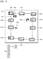
- FIG. 8 illustrates an exemplary indoor map in a virtual tour, according to an embodiment.
- the virtual tour operates in the grid view mode.
- An index of an image currently displayed may be IMG[i].
- the image currently displayed may correspond to a thumbnail 826a.
- an input to select one of thumbnails 826 displayed in a map 820 may be received.
- the thumbnail 826f may be selected in response to the input.
- an image corresponding to the selected thumbnail 826f may be identified.
- a relative order of the identified image with respect to the image currently displayed in the virtual tour may be determined.
- an index of the identified image may be determined as IMG[i+n] when the identified image is nth following to the image currently displayed in the virtual tour.
- the identified image is nth prior to the image currently displayed in the virtual tour, and the index of the identified image may be determined as IMG[i-n].
- n may be 5 according to the thumbnail 826a corresponding to the image currently displayed in the virtual tour, and the selected thumbnail 826f.
- a user in the virtual tour may be navigated to the identified image based on the determined relative order of the identified image.
- the virtual tour in which an image corresponding to the current point has been displayed may be played or fast forwarded until the image corresponding to the selected thumbnail 826f is displayed in the virtual tour.
- the index of the identified image is IMG[i+n]
- the virtual tour may be played or fast forwarded through images of IMG[i+1], IMG[i+2],..., and IMG[i+n-1] until the identified image is displayed.
- speed of the fast forwarding virtual tour may be determined based on the number of images between the images of IMG[i] and IMG[i+n]. For example, the speed of the fast forwarding of virtual tour may be faster, as the more images lies between the images of IMG[i] and IMG[i+n].
- the point corresponding to the selected thumbnail is prior to the current point according to the order of points or the images
- the virtual tour in which the image corresponding to the current point has been displayed may be rewound until the image corresponding to the selected thumbnail is displayed in the virtual tour.
- the index of the identified image is IMG[i-n]
- the virtual tour may be rewound through images of IMG[i-1], IMG[i-2], ... ... and IMG[i-n+1] until the identified image is displayed.
- speed of the rewinding virtual tour may be determined based on the number of images between the images of IMG[i] and IMG[i-n]. For example, the speed of the rewinding of the virtual tour may be faster, as the more images lies between the images of IMG[i] and IMG[i-n].
- the identified image may be displayed.
- the virtual tour may be played in normal speed according to order of the images or the points after the identified image is displayed.
- the virtual tour may be played, paused, or stopped, after the user moved to the point corresponding to the selected thumbnail 826f in the virtual tour.
- the virtual tour in which the image corresponding to the selected thumbnail 826f has been displayed may start to be played according to the order of the points or the images.
- the virtual tour may be an indoor virtual tour, an outdoor virtual tour, or a combination thereof for a house, an office, garden, a shopping mall, a department store, a hotel, or a resort.
- the virtual tour may allow a user to tag the thumbnails 826 with a label such as icons 828, so it may be easy for users to notice where an object or a place such as printers, restrooms, drinking water fountains, fire exists, or the like that the user look for is located in the map 820.
- plurality of virtual tours may be combined to generate a single virtual tour by using location information, orientation information, or height information of images of the virtual tours.
- the plurality of the virtual tours are indoor virtual tours, and each of the virtual tours correspond to different floors, the height information of images of the virtual tours may be used to determine relations between the plurality of virtual tours and the floors.
- the virtual tour may operate in an augmented reality mode.
- FIG. 6 illustrates an example method 600 for interacting with a virtual tour in an augmented reality mode, according to an embodiment.
- FIGs. 9A-9C illustrate an exemplary navigating of a virtual tour in an augmented reality mode, according to an embodiment.
- an image 910 and a mini-map 920 may be displayed in a virtual tour 900.
- the currently displayed image 910 corresponds to a current point 924a included among points along a route 922.
- the augmented reality mode may be triggered in the virtual tour 900 in response to an input P3 with regard to the currently displayed image 910.
- an image 911 and at least one indicator 916 may be displayed in the virtual tour 900 of an augmented reality mode.
- An index of the image 911 displayed in the virtual tour 900 of the augmented reality mode may be IMG[i].
- the at least one indicator 916 may be displayed on the image 911 displayed in the virtual tour 900, and indicators 916 may correspond to the points along the route 922.
- the location of the indicators 916 displayed on the image 911 may correspond to locations and orientation angles of the points with respect to a reference point.
- the location of the indicators 916 displayed on the image 911 may correspond to an image analysis of images or image registration of the images. Referring to Fig. 9B , images corresponding to indicators 916A and 916B may be included in a first set of images, images corresponding to indicators 916B, 916C, 916D may be included in included in a second set of images, and images corresponding to an indicator 916B may be included in a set of turn images.
- the images corresponding to indicators 916A and 916B may be registered with each other, and the registered image of an indicator 916B is overlapped with the registered image of an indicator 916A.
- the location of the indicators may be determined according to a location of the registered image of an indicator 916B in the registered image of an indicator 916A.
- locations of the indicators 916 or distances between the indicators 916 may correspond to distances between the current point 924b and points corresponding to the indicators 916.
- the locations of the indicators 916 may correspond to distances between the point corresponding to the indicators 916 and prior points in the route 922.
- a size or a shape of a graphic representation of the indicators 916 such as arrows or triangles, may correspond or be proportional to the distances.
- the indicators 916 may correspond to orientation angles of the current point 924b and points corresponding to the indicators 916 with respect to a reference point.
- the reference point may be the current point 924b or one of the points corresponding to the indicators 916.
- the indicators 916 may correspond to orientation angles of the points corresponding to the indicators 916 and prior points in the route 922 with respect to a reference point.
- the reference point may be one of the points corresponding to the indicators 916 or one of the prior points in the route 922.
- the indicators 916 may correspond to differences between orientation angles of the point corresponding to the indicators 916 and prior points in the route 922, a direction of a graphic representation of the indicators 916 such as arrows or triangles may correspond to the orientation subtracted by orientation angles of the point corresponding to the indicators 916 from orientation angles of the prior points in the route 922.
- the indicators 916 may correspond to directions from the current point 924b to points corresponding to the indicators 916. In particular embodiments, the indicators 916 may correspond to directions from prior points to the points corresponding to the indicators 916. As an example and not by way of limitation, a direction of the graphic representation of the indicators 916 may correspond to the directions.
- the indicator 916 may correspond to a progress direction on the route 922 in the virtual tour 900.
- an indicator corresponding to a current point of a user in the virtual tour or an indicator closest to the current point may be displayed in the bottom-middle of a currently displayed image.
- a location of indicators may be determined based on a location of the indicator corresponding to the current point and a depth map generated based on registration of a set of images including the currently displayed image.
- the distances, the orientation angles, the difference between the orientation angles, or the direction may be determined based on at least one of an image analysis of corresponding images and information sensed during capture of corresponding images.
- the image analysis may be based on optical flow of the first and second images, or focus of attention and focus of expansion between the first and second images.
- the sensed information may be used to count steps taken between locations where the corresponding images were captured, and the distances may be determined based on the number of steps between points.
- the indicator may be displayed with a label representing the number of steps.
- the indicators 916 may correspond to displacements from the current point 916b to the points corresponding to the indicators 916.
- the displacements may be determined based on at least one of the image analysis of the corresponding images, and information sensed during capture of the corresponding images
- the indicator may correspond to a moving distance from the current point 916b to the points corresponding to the indicators 916.
- the moving distance from the current point 916b to the points corresponding to the indicators 916 may be determined based on at least one of the image analysis and the information sensed during capture of the corresponding images.
- an input P5 to select one of the indicators 916 may be received.
- An index of the selected indicator 916c may be obtained.
- the index of the selected indicator 916c may be obtained based on a distance between points 924b and 924c of the displayed image 911 and an image 912 destined to be displayed.
- the index of the selected indicator 916c may be "i+n", and an index of the image 912 corresponding to the selected indicator 916c may be IMG[i+n].
- a direction of the selected indicator 916c may be determined.
- previous indexes may be obtained, that is, indexes of prior points in the route may be obtained.
- a progress bar 940 may be displayed in the virtual tour 900, the seeking of the virtual tour 900 may be performed with aid of the progress bar 940.
- an input P4 to select " play " or " pause " may be received to play or to pause the virtual tour 900.
- the image 912 may be displayed in the virtual tour 900 where indicators 917 may be displayed.
- An indicator 917a may correspond to a point prior to the 916c.
- the virtual tour may be rewound.
- the image 911 may be displayed again.
- additional information related to an image or a point may be displayed in the augmented reality mode.
- the additional information may be related to a point where the image is captured.
- the grid view mode or the augmented reality mode may be triggered in response to a user input.
- a virtual tour may be displayed according to inputs by a user.
- FIG. 10 illustrates an exemplary scene of a virtual tour in an augmented reality mode, according to an embodiment.
- a image 1010 may be displayed in a virtual tour 1000, and indicators 1012 may be displayed on the image 1010.
- Locations of indicators 1012 may be determined based on locations and orientation angles of points forming a route in the virtual tour 1000.
- the indicators 1012 may correspond to orientation angles of points.
- the indicators 1012 may correspond to a difference between orientation angles of a first point and a second point next to the first point. For example, directions at which the indicators 1012 points may be determined the difference between orientation angles of the first point and the second point next to the first point.
- first images corresponding to indicators 1012a, 1012b, 1012c, and 1012d may be included in a first set of walk images
- second images corresponding to indicators 1012d, and 1012e may be included in a second set of walk images.
- At least one image corresponding to an indicator 1012 may be turn images.
- Locations of the indicators 1012a, 1012b, 1012c, and 1012d or distances between the indicators 1012a, 1012b, 1012c, and 1012d may be determined based on a depth map which is generated based on registration of the first images.
- the users may be provided with a virtual tour for a hotel.
- Static data 1022e such as names and brief description of the facilities and its location such as Lounge, Universities, swimming pools, or the like provided by hotel management.
- the run-time pop-up data in the augmented reality mode provides assistance to the users.
- updates 1022c from the hotel may be received and the virtual tour in a user device may be updated accordingly. For example, operational times of the facilities, cuisine information for various restaurants or the like may be updated.
- hotels and shopping malls may provide either tablets or mobile applications to users for virtual tours of the hotels and the shopping malls. These applications may receive an update from an internet-based server maintained by the hotels and the shopping malls.
- Wireless-Fidelity (Wi-Fi) based Positioning System fused with Global Positioning System (GPS) data may be used to enable real-time tracking (i.e., tracking data is used to traverse or seek the virtual tour and render accordingly).
- GPS Global Positioning System
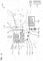
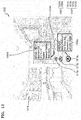
- FIG. 11 illustrates an exemplary scene of a virtual tour in an augmented reality mode, according to an embodiment.
- a image 1110 may be displayed in a virtual tour 1100, and indicators 1112 may be displayed on the image 1110.
- the users may be provided with a virtual tour having multi-level map features.
- the static data 1122c such as names and brief description of specific stores, cinemas, or the like may be displayed in the augmented reality mode.
- the virtual tour and the multi-level maps may be based on the tracking data in real time.
- the augmented reality mode provides scene data in the vicinity of current position of the users in real time, and which may provide the user with scene information of an area the user is walking into.
- Updates 1122f from the offices may be received in a user device, and displayed in the virtual tour. For example, discounts and sale offers, arrival of new collections, or the like may be displayed in the virtual tour in response to receiving the updates.
- FIG. 12 illustrates an exemplary scene of a virtual tour in an augmented reality mode, according to an embodiment.
- a image 1210 may be displayed in a virtual tour 1200, and indicators 1212 may be displayed on the image 1210.
- the virtual tour 1200 of the home (i.e., property) for sale may be displayed in a user device.
- the static data 1222d such as room purpose, dimensions, and brief description 1222a of style and nature of amenities are displayed in the augmented reality mode.
- FIG. 15 illustrates an exemplary method of image registration based on distances between points, according to an embodiment.
- FIGs. 16A and 16B illustrate an exemplary navigating of a virtual tour based on a depth map, according to an embodiment.
- distances between points of a set of images may be calculated.
- the distances between the points of the set of images may be determined according to an image analysis of the set of images.
- the image analysis may be based on optical flow of the set of images, or focus of attention and focus of expansion between the set of images.
- the distance between the points of the set of images may be determined based on information sensed during capture of the set of images. The sensed information may be used to count steps taken between locations where the set of images are captured, and the distance between the points of the set of images may be determined based on the number of steps.
- image registration may be performed based on the calculated distances.
- the method of image registration is described in connection with Figs. 13 and 14 .
- depth values of a set of images in a depth map are determined based on distances between points of the set of images.
- the depth map may be generated using alignment factor, or calibration data of the set of images.
- the depth map is characterized by the amount of user walked into the scene. As the user walks less into the scene in the virtual tour, a depth value may decrease in the depth map accordingly, that is, a distance that the user walks into the scene in the virtual tour may be proportional to difference between depth values of images before and after the user walk.
- a movement 1610a in the virtual tour 1600 may correspond to changes of a depth value in a depth map 1620a.
- a depth value may increase more than ones caused by movement 1610a.
- FIG. 17 illustrates an exemplary method 1700 for computing calibration data, according to an embodiment.
- process for calibrating data may be initialized, and the processor may be based on the number of steps (k) within a step limit of ⁇ n'.
- a dataset of images may be selected, at operation 1706.
- a transformation matrix may be calculated using image registration of a set of images.
- calibration data may be computed based on the calculated transformation matrix.
- the calibration data for the set of images may be an average of the transformation matrix.
- FIG. 18 illustrates an exemplary method 1800 for rendering a virtual tour, according to an embodiment.
- a process for rendering the set of images may be initiated.
- image registration is performed on the set of images.
- the image registration method for generating the depth map is described in conjunction with the FIGs. 13 and 14 .
- the transformation matrix may be obtained, and then a depth map is generated at operation 1810.
- the virtual tour is rendered based on the generated depth map.
- a calibration matrix may be calculated based on an image registration of a set of images using the calibration data which is described in conjunction with the FIG. 17 .
- an artificial 3-D effect may be generated based on the depth maps while the set of images are displayed.
- the depth map may be generated based on the image registration of the set of images when the image registration is successful. In the case of failure of the image registration, the numbers of steps between the set of images may be used to generate the depth map.
- FIG. 19 illustrates an exemplary method 1900 for converting a two dimensional (2D) image to a three dimensional (3D) image using a depth map, according to an embodiment.
- areas corresponding to registered images in a depth map may be enlarged based on sizes of a set of images.
- the areas corresponding to the registered images in the depth map may be enlarged based on rectangular transition coordinates of the set of images.
- 3D mesh may be generated based on the depth map.
- the generated 3D mesh may be textured.
- FIG. 20 illustrates exemplary of 3D meshes. The sample meshes 2010, 2012, 2014, and 2018 for rectangular transition coordination 2000, 2002, 2004, and 2008 are shown in the FIG. 20 .
- FIG. 21 illustrates an exemplary method for rendering 3D images, according to an embodiment.
- 2D images may be converted to 3D images based on a depth map.
- the 3D images may be rendered based on rectangular transition coordinates of a set of images.
- the rendering may be performed based on a depth value. For example, the rendering may be performed on images with lower depth values earlier than ones with higher depth value.
- artificial depth may be given to the image scene by a depth map.
- the navigating of a virtual tour may start at an image with the lowest depth value, and proceed according to depth values of images.
- a position of a virtual camera may be placed at a point corresponding to the image with the lowest depth value.
- the virtual camera may be moved to a point corresponding to an image with the highest depth value.
- alignment factors may be considered to generate the depth map.
- Depth levels of the depth map may be determined based on sequence of transformation.
- a route in the virtual tour may be determined based on the sequence of the transformation.
- Depth levels of the depth map may be determined based on sequence of image registration.
- a route in the virtual tour may be determined based on the sequence of the image registration.
- a depth map for a set of images, and turn alignments for turn images may be calculated during capture of images.
- Different depth levels in the depth map may cause a user to be immersed in a virtual environment.
- FIG. 22 illustrates an exemplary computer system in which embodiments can be implemented.
- one or more computer systems 2200 perform one or more operations of one or more methods described or illustrated herein.
- one or more computer systems 2200 provide functionality described or illustrated herein.
- software running on one or more computer systems 2200 performs one or more operations of one or more methods described or illustrated herein or provides functionality described or illustrated herein.
- Particular embodiments include one or more portions of one or more computer systems 2200.
- reference to a computer system may encompass a computing device, and vice versa, where appropriate.
- reference to a computer system may encompass one or more computer systems, where appropriate.
- computer system 2200 may be an embedded computer system, a system-on-chip (SOC), a single-board computer system (SBC) (such as, for example, a computer-on-module (COM) or system-on-module (SOM)), a desktop computer system, a laptop or notebook computer system, an interactive kiosk, a mainframe, a mesh of computer systems, a mobile telephone, a personal digital assistant (PDA), a server, a tablet computer system, or a combination of two or more of these.
- SOC system-on-chip
- SBC single-board computer system
- COM computer-on-module
- SOM system-on-module
- computer system 2200 may include one or more computer systems 2200; be unitary or distributed; span multiple locations; span multiple machines; span multiple data centers; or reside in a cloud, which may include one or more cloud components in one or more networks.
- one or more computer systems 2200 may perform without substantial spatial or temporal limitation one or more operations of one or more methods described or illustrated herein.
- one or more computer systems 2200 may perform in real time or in batch mode one or more operations of one or more methods described or illustrated herein.
- One or more computer systems 2200 may perform at different times or at different locations one or more operations of one or more methods described or illustrated herein, where appropriate.
- computer system 2200 includes a processor 2202, memory 2204, storage 2206, an input/output (I/O) interface 2208, a communication interface 2210, and a bus 2212.
- I/O input/output
- this disclosure describes and illustrates a particular computer system having a particular number of particular components in a particular arrangement, this disclosure contemplates any suitable computer system having any suitable number of any suitable components in any suitable arrangement.
- processor 2202 includes hardware for executing instructions, such as those making up a computer program.
- processor 2202 may retrieve (or fetch) the instructions from an internal register, an internal cache, memory 2204, or storage 2206; decode and execute them; and then write one or more results to an internal register, an internal cache, memory 2204, or storage 2206.
- processor 2202 may include one or more internal caches for data, instructions, or addresses. This disclosure contemplates processor 2202 including any suitable number of any suitable internal caches, where appropriate.
- processor 2202 may include one or more instruction caches, one or more data caches, and one or more translation lookaside buffers (TLBs).
- TLBs translation lookaside buffers
- Instructions in the instruction caches may be copies of instructions in memory 2204 or storage 2206, and the instruction caches may speed up retrieval of those instructions by processor 2202.
- Data in the data caches may be copies of data in memory 2204 or storage 2206 for instructions executing at processor 2202 to operate on; the results of previous instructions executed at processor 2202 for access by subsequent instructions executing at processor 2202 or for writing to memory 2204 or storage 2206; or other suitable data.
- the data caches may speed up read or write operations by processor 2202.
- the TLBs may speed up virtual-address translation for processor 2202.
- processor 2202 may include one or more internal registers for data, instructions, or addresses. This disclosure contemplates processor 2202 including any suitable number of any suitable internal registers, where appropriate. Where appropriate, processor 2202 may include one or more arithmetic logic units (ALUs); be a multi-core processor; or include one or more processors 2202. Although this disclosure describes and illustrates a particular processor, this disclosure contemplates any suitable processor.
- ALUs
- memory 2204 includes main memory for storing instructions for processor 2202 to execute or data for processor 2202 to operate on.
- computer system 2200 may load instructions from storage 2206 or another source (such as, for example, another computer system 2200) to memory 2204.
- Processor 2202 may then load the instructions from memory 2204 to an internal register or internal cache.
- processor 2202 may retrieve the instructions from the internal register or internal cache and decode them.
- processor 2202 may write one or more results (which may be intermediate or final results) to the internal register or internal cache.
- Processor 2202 may then write one or more of those results to memory 2204.
- processor 2202 executes only instructions in one or more internal registers or internal caches or in memory 2204 (as opposed to storage 2206 or elsewhere) and operates only on data in one or more internal registers or internal caches or in memory 2204 (as opposed to storage 2206 or elsewhere).
- One or more memory buses (which may each include an address bus and a data bus) may couple processor 2202 to memory 2204.
- Bus 2212 may include one or more memory buses, as described below.
- one or more memory management units reside between processor 2202 and memory 2204 and facilitate accesses to memory 2204 requested by processor 2202.
- memory 2204 includes random access memory (RAM).
- This RAM may be volatile memory, where appropriate, and this RAM may be dynamic RAM (DRAM) or static RAM (SRAM), where appropriate. Moreover, where appropriate, this RAM may be single-ported or multi-ported RAM.
- Memory 2204 may include one or more memories 2204, where appropriate. Although this disclosure describes and illustrates particular memory, this disclosure contemplates any suitable memory.
- storage 2206 includes mass storage for data or instructions.
- storage 2206 may include a hard disk drive (HDD), a floppy disk drive, flash memory, an optical disc, a magneto-optical disc, magnetic tape, or a Universal Serial Bus (USB) drive or a combination of two or more of these.
- Storage 2206 may include removable or non-removable (or fixed) media, where appropriate.
- Storage 2206 may be internal or external to computer system 2200, where appropriate.
- storage 2206 is non-volatile, solid-state memory.
- storage 2206 includes read-only memory (ROM).
- this ROM may be mask-programmed ROM, programmable ROM (PROM), erasable PROM (EPROM), electrically erasable PROM (EEPROM), electrically alterable ROM (EAROM), or flash memory or a combination of two or more of these.
- This disclosure contemplates mass storage 2206 taking any suitable physical form.
- Storage 2206 may include one or more storage control units facilitating communication between processor 2202 and storage 2206, where appropriate.
- storage 2206 may include one or more storages 2206.
- this disclosure describes and illustrates particular storage, this disclosure contemplates any suitable storage.
- I/O interface 2208 includes hardware, software, or both, providing one or more interfaces for communication between computer system 2200 and one or more I/O devices.
- Computer system 2200 may include one or more of these I/O devices, where appropriate.
- One or more of these I/O devices may enable communication between a person and computer system 2200.
- an I/O device may include a keyboard, keypad, microphone, monitor, mouse, printer, scanner, speaker, still camera, stylus, tablet, touch screen, trackball, video camera, another suitable I/O device or a combination of two or more of these.
- An I/O device may include one or more sensors. This disclosure contemplates any suitable I/O devices and any suitable I/O interfaces 2208 for them.
- I/O interface 2208 may include one or more device or software drivers enabling processor 2202 to drive one or more of these I/O devices.
- I/O interface 2208 may include one or more I/O interfaces 2208, where appropriate.
- communication interface 2210 includes hardware, software, or both providing one or more interfaces for communication (such as, for example, packet-based communication) between computer system 2200 and one or more other computer systems 2200 or one or more networks.
- communication interface 2210 may include a network interface controller (NIC) or network adapter for communicating with an Ethernet or other wire-based network or a wireless NIC (WNIC) or wireless adapter for communicating with a wireless network, such as a WI-FI network.
- NIC network interface controller
- WNIC wireless NIC
- WI-FI network wireless network
- computer system 2200 may communicate with an ad hoc network, a personal area network (PAN), a local area network (LAN), a wide area network (WAN), a metropolitan area network (MAN), body area network (BAN), or one or more portions of the Internet or a combination of two or more of these.
- PAN personal area network
- LAN local area network
- WAN wide area network
- MAN metropolitan area network
- BAN body area network
- One or more portions of one or more of these networks may be wired or wireless.
- computer system 2200 may communicate with a wireless PAN (WPAN) (such as, for example, a BLUETOOTH WPAN), a WI-FI network, a WI-MAX network, a cellular telephone network (such as, for example, a Global System for Mobile Communications (GSM) network), or other suitable wireless network or a combination of two or more of these.
- WPAN wireless PAN
- WI-FI wireless personal area network
- WI-MAX wireless personal area network
- cellular telephone network such as, for example, a Global System for Mobile Communications (GSM) network
- GSM Global System for Mobile Communications
- Computer system 2200 may include any suitable communication interface 2210 for any of these networks, where appropriate.
- Communication interface 2210 may include one or more communication interfaces 2210, where appropriate.
- bus 2212 includes hardware, software, or both coupling components of computer system 2200 to each other.
- bus 2212 may include an Accelerated Graphics Port (AGP) or other graphics bus, an Enhanced Industry Standard Architecture (EISA) bus, a front-side bus (FSB), a HYPERTRANSPORT (HT) interconnect, an Industry Standard Architecture (ISA) bus, an INFINIBAND interconnect, a low-pin-count (LPC) bus, a memory bus, a Micro Channel Architecture (MCA) bus, a Peripheral Component Interconnect (PCI) bus, a PCI-Express (PCIe) bus, a serial advanced technology attachment (SATA) bus, a Video Electronics Standards Association local (VLB) bus, or another suitable bus or a combination of two or more of these.
- Bus 2212 may include one or more buses 2212, where appropriate.
- a computer-readable non-transitory storage medium or media may include one or more semiconductor-based or other integrated circuits (ICs) (such, as for example, field-programmable gate arrays (FPGAs) or application-specific ICs (ASICs)), hard disk drives (HDDs), hybrid hard drives (HHDs), optical discs, optical disc drives (ODDs), magneto-optical discs, magneto-optical drives, floppy diskettes, floppy disk drives (FDDs), magnetic tapes, solid-state drives (SSDs), RAM-drives, SECURE DIGITAL cards or drives, any other suitable computer-readable non-transitory storage media, or any suitable combination of two or more of these, where appropriate.
- ICs such, as for example, field-programmable gate arrays (FPGAs) or application-specific ICs (ASICs)
- HDDs hard disk drives
- HHDs hybrid hard drives
- ODDs optical disc drives
- magneto-optical discs magneto-optical drives
- an apparatus or system or a component of an apparatus or system being adapted to, arranged to, capable of, configured to, enabled to, operable to, or operative to perform a particular function encompasses that apparatus, system, component, whether or not it or that particular function is activated, turned on, or unlocked, as long as that apparatus, system, or component is so adapted, arranged, capable, configured, enabled, operable, or operative.
Landscapes
- Engineering & Computer Science (AREA)
- Physics & Mathematics (AREA)
- Theoretical Computer Science (AREA)
- General Physics & Mathematics (AREA)
- Computer Graphics (AREA)
- Software Systems (AREA)
- Computer Vision & Pattern Recognition (AREA)
- Computer Hardware Design (AREA)
- General Engineering & Computer Science (AREA)
- Radar, Positioning & Navigation (AREA)
- Remote Sensing (AREA)
- Geometry (AREA)
- Computing Systems (AREA)
- User Interface Of Digital Computer (AREA)
- Processing Or Creating Images (AREA)
Applications Claiming Priority (2)
| Application Number | Priority Date | Filing Date | Title |
|---|---|---|---|
| IN1061CH2015 | 2015-03-04 | ||
| IN721CH2015 | 2016-01-21 |
Publications (1)
| Publication Number | Publication Date |
|---|---|
| EP3065108A1 true EP3065108A1 (fr) | 2016-09-07 |
Family
ID=55637161
Family Applications (1)
| Application Number | Title | Priority Date | Filing Date |
|---|---|---|---|
| EP16158769.6A Ceased EP3065108A1 (fr) | 2015-03-04 | 2016-03-04 | Affichage d'une visite virtuelle |
Country Status (2)
| Country | Link |
|---|---|
| US (1) | US10629001B2 (fr) |
| EP (1) | EP3065108A1 (fr) |
Cited By (1)
| Publication number | Priority date | Publication date | Assignee | Title |
|---|---|---|---|---|
| CN107655469A (zh) * | 2017-08-29 | 2018-02-02 | 黄小云 | 一种基于增强现实的取药系统 |
Families Citing this family (13)
| Publication number | Priority date | Publication date | Assignee | Title |
|---|---|---|---|---|
| US10096158B2 (en) * | 2016-03-24 | 2018-10-09 | Ford Global Technologies, Llc | Method and system for virtual sensor data generation with depth ground truth annotation |
| US10977735B1 (en) * | 2016-06-30 | 2021-04-13 | State Farm Mutual Automobile Insurance Company | Providing user interaction data associated with a property |
| US11023984B1 (en) | 2017-04-20 | 2021-06-01 | Wells Fargo Bank, N.A. | Virtual property appraisals and/or inspections |
| IT201700058961A1 (it) * | 2017-05-30 | 2018-11-30 | Artglass S R L | Metodo e sistema di fruizione di un contenuto editoriale in un sito preferibilmente culturale o artistico o paesaggistico o naturalistico o fieristico o espositivo |
| US11227440B2 (en) * | 2018-05-30 | 2022-01-18 | Ke.com (Beijing)Technology Co., Ltd. | Systems and methods for providing an audio-guided virtual reality tour |
| US12148314B2 (en) * | 2021-01-07 | 2024-11-19 | Honeywell International Inc. | System and method for dynamically augmenting raster charts displayed on a cockpit display |
| US11481983B2 (en) * | 2020-11-25 | 2022-10-25 | At&T Intellectual Property I, L.P. | Time shifting extended reality media |
| US11360576B1 (en) * | 2020-12-21 | 2022-06-14 | International Business Machines Corporation | Movement pattern-based mobile device user interfaces |
| FI20215160A1 (en) * | 2021-02-17 | 2022-08-18 | Procemex Oy Ltd | Extended virtual tour |
| US11734893B2 (en) * | 2021-08-17 | 2023-08-22 | Sony Interactive Entertainment LLC | Curating virtual tours |
| US12373904B2 (en) * | 2022-05-27 | 2025-07-29 | Giraffe360 Limited | Synchronized presentation of scheduled guided viewings |
| US12400381B2 (en) * | 2023-01-17 | 2025-08-26 | Tmrw Group Ip | Dynamically generated virtual environments |
| US20260046371A1 (en) * | 2024-08-12 | 2026-02-12 | Footprn Technologies Llc | Method and system for remote viewing of real estate |
Citations (1)
| Publication number | Priority date | Publication date | Assignee | Title |
|---|---|---|---|---|
| EP2817785A2 (fr) * | 2012-02-23 | 2014-12-31 | Charles D. Huston | Système et procédé de création d'un environnement et de partage d'expérience en fonction d'un emplacement dans un environnement |
Family Cites Families (14)
| Publication number | Priority date | Publication date | Assignee | Title |
|---|---|---|---|---|
| US6388688B1 (en) * | 1999-04-06 | 2002-05-14 | Vergics Corporation | Graph-based visual navigation through spatial environments |
| US20080086696A1 (en) * | 2006-03-03 | 2008-04-10 | Cadcorporation.Com Inc. | System and Method for Using Virtual Environments |
| WO2010019205A1 (fr) * | 2008-08-12 | 2010-02-18 | Google Inc. | Visite dans un système d'informations géographiques |
| US8823707B2 (en) * | 2010-11-24 | 2014-09-02 | Google Inc. | Guided navigation through geo-located panoramas |
| US20150154798A1 (en) * | 2011-12-30 | 2015-06-04 | Google Inc. | Visual Transitions for Photo Tours Between Imagery in a 3D Space |
| US20150332494A1 (en) * | 2012-03-26 | 2015-11-19 | Google Inc. | Providing an image tour of a point of interest |
| US9395875B2 (en) * | 2012-06-27 | 2016-07-19 | Ebay, Inc. | Systems, methods, and computer program products for navigating through a virtual/augmented reality |
| KR101957943B1 (ko) | 2012-08-31 | 2019-07-04 | 삼성전자주식회사 | 정보 제공 방법 및 이를 위한 정보 제공 차량 |
| US9345965B2 (en) * | 2012-09-17 | 2016-05-24 | King.Com Ltd. | Method for implementing a computer game |
| KR101489064B1 (ko) | 2013-04-23 | 2015-02-02 | 현대엠엔소프트 주식회사 | 교통혼잡정보를 내비게이션의 가상공간에 표시하는 장치 및 방법 |
| US9367962B2 (en) * | 2013-10-22 | 2016-06-14 | Topcon Positioning Systems, Inc. | Augmented image display using a camera and a position and orientation sensor |
| US9196027B2 (en) * | 2014-03-31 | 2015-11-24 | International Business Machines Corporation | Automatic focus stacking of captured images |
| US9189839B1 (en) * | 2014-04-24 | 2015-11-17 | Google Inc. | Automatically generating panorama tours |
| US9575564B2 (en) * | 2014-06-17 | 2017-02-21 | Chief Architect Inc. | Virtual model navigation methods and apparatus |
-
2016
- 2016-03-04 EP EP16158769.6A patent/EP3065108A1/fr not_active Ceased
- 2016-03-04 US US15/061,367 patent/US10629001B2/en active Active
Patent Citations (1)
| Publication number | Priority date | Publication date | Assignee | Title |
|---|---|---|---|---|
| EP2817785A2 (fr) * | 2012-02-23 | 2014-12-31 | Charles D. Huston | Système et procédé de création d'un environnement et de partage d'expérience en fonction d'un emplacement dans un environnement |
Non-Patent Citations (2)
| Title |
|---|
| ANONYMOUS: "Photosynth - Wikipedia, the free encyclopedia", 26 February 2013 (2013-02-26), pages 1 - 4, XP055131993, Retrieved from the Internet <URL:http://en.wikipedia.org/w/index.php?title=Photosynth&oldid=540666238> [retrieved on 20140728] * |
| URICCHIO W: "The algorithmic turn: photosynth, augmented reality and the changing implications of the image", VISUAL STUDIES,, vol. 26, no. 1, 1 March 2011 (2011-03-01), pages 25 - 35, XP009178875, ISSN: 1472-586X, DOI: 10.1080/1472586X.2011.548486 * |
Cited By (1)
| Publication number | Priority date | Publication date | Assignee | Title |
|---|---|---|---|---|
| CN107655469A (zh) * | 2017-08-29 | 2018-02-02 | 黄小云 | 一种基于增强现实的取药系统 |
Also Published As
| Publication number | Publication date |
|---|---|
| US10629001B2 (en) | 2020-04-21 |
| US20160260253A1 (en) | 2016-09-08 |
Similar Documents
| Publication | Publication Date | Title |
|---|---|---|
| US10629001B2 (en) | Method for navigation in an interactive virtual tour of a property | |
| US12067772B2 (en) | Methods and apparatus for venue based augmented reality | |
| AU2023200413B2 (en) | Automated control of image acquisition via use of mobile device user interface | |
| US11164361B2 (en) | Generating floor maps for buildings from automated analysis of visual data of the buildings' interiors | |
| US8988426B2 (en) | Methods and apparatus for rendering labels based on occlusion testing for label visibility | |
| US10354452B2 (en) | Directional and x-ray view techniques for navigation using a mobile device | |
| US9269196B1 (en) | Photo-image-based 3D modeling system on a mobile device | |
| CN109146954B (zh) | 用于与所显示的地图进行交互的增强现实界面 | |
| US10719981B2 (en) | Generating a three-dimensional model using a portable electronic device recording | |
| US9888215B2 (en) | Indoor scene capture system | |
| US8464181B1 (en) | Floor selection on an interactive digital map | |
| CA2906181C (fr) | Inclinaison pour defilement | |
| Sankar et al. | Capturing indoor scenes with smartphones | |
| US20140245232A1 (en) | Vertical floor expansion on an interactive digital map | |
| US20100188397A1 (en) | Three dimensional navigation using deterministic movement of an electronic device | |
| US20150153172A1 (en) | Photography Pose Generation and Floorplan Creation | |
| CN107924582A (zh) | 在三维环境中的视点之间转换的系统和方法 | |
| US20130271452A1 (en) | Mechanism for facilitating context-aware model-based image composition and rendering at computing devices | |
| JP2010231741A (ja) | 電子タグ作成表示システム、電子タグ作成表示装置およびそれらの方法 | |
| US20240126381A1 (en) | Tracking a handheld device | |
| Bindschaedler et al. | Making Mobile Augmented Reality A Reality |
Legal Events
| Date | Code | Title | Description |
|---|---|---|---|
| PUAI | Public reference made under article 153(3) epc to a published international application that has entered the european phase |
Free format text: ORIGINAL CODE: 0009012 |
|
| 17P | Request for examination filed |
Effective date: 20160304 |
|
| AK | Designated contracting states |
Kind code of ref document: A1 Designated state(s): AL AT BE BG CH CY CZ DE DK EE ES FI FR GB GR HR HU IE IS IT LI LT LU LV MC MK MT NL NO PL PT RO RS SE SI SK SM TR |
|
| AX | Request for extension of the european patent |
Extension state: BA ME |
|
| STAA | Information on the status of an ep patent application or granted ep patent |
Free format text: STATUS: EXAMINATION IS IN PROGRESS |
|
| 17Q | First examination report despatched |
Effective date: 20170712 |
|
| STAA | Information on the status of an ep patent application or granted ep patent |
Free format text: STATUS: THE APPLICATION HAS BEEN REFUSED |
|
| 18R | Application refused |
Effective date: 20200927 |