EP3065155A1 - Schaltstruktur und explosionsgeschützte vorrichtung - Google Patents
Schaltstruktur und explosionsgeschützte vorrichtung Download PDFInfo
- Publication number
- EP3065155A1 EP3065155A1 EP14858052.5A EP14858052A EP3065155A1 EP 3065155 A1 EP3065155 A1 EP 3065155A1 EP 14858052 A EP14858052 A EP 14858052A EP 3065155 A1 EP3065155 A1 EP 3065155A1
- Authority
- EP
- European Patent Office
- Prior art keywords
- magnetic
- container
- explosion
- hermetically sealed
- magnet
- Prior art date
- Legal status (The legal status is an assumption and is not a legal conclusion. Google has not performed a legal analysis and makes no representation as to the accuracy of the status listed.)
- Granted
Links
Images



Classifications
-
- H—ELECTRICITY
- H01—ELECTRIC ELEMENTS
- H01H—ELECTRIC SWITCHES; RELAYS; SELECTORS; EMERGENCY PROTECTIVE DEVICES
- H01H9/00—Details of switching devices, not covered by groups H01H1/00 - H01H7/00
- H01H9/02—Bases, casings, or covers
- H01H9/04—Dustproof, splashproof, drip-proof, waterproof, or flameproof casings
- H01H9/042—Explosion-proof cases
-
- H—ELECTRICITY
- H01—ELECTRIC ELEMENTS
- H01H—ELECTRIC SWITCHES; RELAYS; SELECTORS; EMERGENCY PROTECTIVE DEVICES
- H01H36/00—Switches actuated by change of magnetic field or of electric field, e.g. by change of relative position of magnet and switch, by shielding
-
- H—ELECTRICITY
- H01—ELECTRIC ELEMENTS
- H01H—ELECTRIC SWITCHES; RELAYS; SELECTORS; EMERGENCY PROTECTIVE DEVICES
- H01H36/00—Switches actuated by change of magnetic field or of electric field, e.g. by change of relative position of magnet and switch, by shielding
- H01H36/02—Switches actuated by change of magnetic field or of electric field, e.g. by change of relative position of magnet and switch, by shielding actuated by movement of a float carrying a magnet
-
- H—ELECTRICITY
- H01—ELECTRIC ELEMENTS
- H01H—ELECTRIC SWITCHES; RELAYS; SELECTORS; EMERGENCY PROTECTIVE DEVICES
- H01H2223/00—Casings
- H01H2223/002—Casings sealed
-
- H—ELECTRICITY
- H01—ELECTRIC ELEMENTS
- H01H—ELECTRIC SWITCHES; RELAYS; SELECTORS; EMERGENCY PROTECTIVE DEVICES
- H01H2235/00—Springs
- H01H2235/01—Spiral spring
-
- H—ELECTRICITY
- H01—ELECTRIC ELEMENTS
- H01H—ELECTRIC SWITCHES; RELAYS; SELECTORS; EMERGENCY PROTECTIVE DEVICES
- H01H36/00—Switches actuated by change of magnetic field or of electric field, e.g. by change of relative position of magnet and switch, by shielding
- H01H36/0006—Permanent magnet actuating reed switches
-
- H—ELECTRICITY
- H01—ELECTRIC ELEMENTS
- H01H—ELECTRIC SWITCHES; RELAYS; SELECTORS; EMERGENCY PROTECTIVE DEVICES
- H01H36/00—Switches actuated by change of magnetic field or of electric field, e.g. by change of relative position of magnet and switch, by shielding
- H01H36/0006—Permanent magnet actuating reed switches
- H01H36/004—Permanent magnet actuating reed switches push-button-operated, e.g. for keyboards
Definitions
- the present invention relates to a switch structure that turns ON/OFF a magnetic sensor arranged in a hermetically sealed container from the outside of the hermetically sealed container, and also relates to an explosion-proof device including the switch structure.
- a hermetically sealed container serves as an explosion-proof container
- a magnetic sensor is arranged in the explosion-proof container
- a switch structure that turns ON/OFF the magnetic sensor from the outside of the explosion-proof container is used (for example, see PTL 1).
- Fig. 6 shows a primary portion of a conventional switch structure used in an explosion-proof device.
- reference sign 10 denotes an explosion-proof container
- 20 denotes a magnetic sensor arranged in the explosion-proof container
- 30 denotes a magnet generating a magnetic field.
- a container wall 10a that separates the inside of the explosion-proof container 10 from the outside is a non-magnetic body.
- the magnet 30 is provided outside the explosion-proof container 10 movably back and forth with respect to the magnetic sensor 20.
- the explosion-proof container 10 houses an electric circuit and an electric part to be protected.
- the magnetic sensor 20 senses the magnetism from the magnet 30 acting through the container wall 10a, and outputs a magnetism sensing signal. If the magnet 30 is moved far from the magnetic sensor 20, the magnetic sensor 20 no longer senses the magnetism from the magnet 30, and the magnetic sensor 20 is turned OFF.
- the switch structure using the magnetic sensor 20 and the magnet 30 allows the operation of the electric circuit housed in the explosion-proof container 10 to be switched and the various settings of the electric circuit to be made from the outside while keeping the explosion-proof performance of the inside of the explosion-proof container 10.
- this switch structure typically has a configuration in which the magnetic sensor 20 and the magnet 30 make a pair, the pair serves as a single magnetic switch 40, and a plurality of the magnetic switches 40 are arranged in parallel.
- magnetic sensors 20-1 to 20-4 are provided in parallel in the explosion-proof container 10
- magnets 30-1 to 30-4 are provided outside the explosion-proof container 10 movably back and forth with respect to the magnetic sensors 20-1 to 20-4, and the magnetic sensors 20-1 to 20-4 and the magnets 30-1 to 30-4 configure magnetic switches 40-1 to 40-4.
- the container wall 10a being the non-magnetic body is located between the magnetic sensors 20-1 to 20-4 and the magnets 30-1 to 30-4.
- a distance L between adjacent two of the magnetic switches 40 is determined as a distance to prevent one magnet 30 from being influenced by the magnetic field of another magnet 30 so that each of the magnetic switches 40 can be independently turned ON/OFF. That is, since the container wall 10a is the non-magnetic body, the magnetic field of each magnet 30 is spread in a wide range. Hence, the distance L between adjacent two of the magnetic switches 40 is sufficiently determined to prevent the magnetic field of the magnet 30 from acting on the other magnetic sensors 20.
- the magnet 30 has had to use a magnet with a strong magnetic force (large magnet) so that the magnetic field of the magnet 30 correctly acts on the magnetic sensor 20 through the container wall 10a.
- the switch structure includes the plurality of magnetic switches 40 arranged in parallel, and if the container wall 10a is thick, the magnets 30 have had to use large magnets, and in addition, since the magnetic fields of the magnets 30 are spread in wide ranges, the distance L between adjacent two of the magnetic switches 40 has had to be increased.
- the container wall 10a has had to be thinned so that the magnetic fields of even magnets having weak magnetic forces (small magnets) correctly act on the magnetic sensors 20. That is, since there are many limitations in view of the layout of respective components, it has been difficult to attain requests on increasing the thickness of the container wall 10a and decreasing the distance L between adjacent two of the magnetic switches 40.
- the invention is made to solve such problems, and an object of the invention is to provide a switch structure that does not have to use a large magnet even if a container wall (non-magnetic body) of a hermetically sealed container is thick. Also, another object of the invention is to provide a switch structure that can decrease the distance between adjacent magnetic switches and individually independently turn ON/OFF magnetic switches even if a container wall (non-magnetic body) of a hermetically sealed container is thick.
- the invention includes a hermetically sealed container including a container wall formed of a non-magnetic body and separating the inside from the outside; a magnet generating a magnetic field; a magnetic sensor arranged in the hermetically sealed container and configured to be turned ON/OFF by the magnetic field of the magnet acting from the outside of the hermetically sealed container through the container wall of the hermetically sealed container; and a first magnetic body provided at the container wall of the hermetically sealed container and serving as a path of the magnetic field acting on the magnetic sensor from the magnet.
- the magnetic field from the magnet acts on the magnetic sensor through the first magnetic body provided at the container wall (non-magnetic body) of the hermetically sealed container.
- the magnetic field from the magnet acts on the magnetic sensor through the first magnetic body provided at the container wall (non-magnetic body) of the hermetically sealed container.
- the magnetic field from the magnet efficiently acts on the magnetic sensor, and the magnet no longer needs to use a large magnet. Also, in the switch structure of the invention, since the magnetic field from the magnet acts on the magnetic sensor through the first magnetic body provided at the container wall (non-magnetic body) of the hermetically sealed container, the range of the magnetic field of the magnet is decreased in size.
- the first magnetic body serving as the path of the magnetic field acting on the magnetic sensor from the magnet is provided at the container wall (non-magnetic body) of the hermetically sealed container, even if the container wall (non-magnetic body) of the hermetically sealed container is thick, the magnetic field from the magnet can efficiently act on the magnetic sensor. The magnet no longer needs to use a large magnet. Also, with the invention, since the magnetic field from the magnet acts on the magnetic sensor through the first magnetic body provided at the container wall (non-magnetic body) of the sealed container, even if the container wall (non-magnetic body) of the hermetically sealed container is thick, the distance between adjacent two of the magnetic switches is decreased, and each magnetic switch can be independently turned ON/OFF.
- Fig. 1 is an illustration showing a primary portion of an embodiment (first embodiment) of a switch structure according to the invention.
- reference sign 1 denotes an explosion-proof container
- 2 denotes a magnetic sensor arranged in the explosion-proof container 1
- 3 denotes a magnet generating a magnetic field.
- a container wall 1 a that separates the inside of the explosion-proof container 1 from the outside is a non-magnetic body.
- the magnet 3 is provided outside the explosion-proof container 1 movably back and forth with respect to the magnetic sensor 2.
- the explosion-proof container 1 houses an electric circuit and an electric part to be protected.
- magnetic bodies 4-1 to 4-4 are provided, in correspondence with magnetic sensors 2-1 to 2-4, at the container wall (non-magnetic body) 1 a arranged between the magnetic sensors 2-1 to 2-4 and magnets 3-1 to 3-4.
- This magnetic body 4 (4-1 to 4-4) has a columnar shape. A first end surface 4a of the magnetic body 4 is exposed to the outside of the explosion-proof container 1, and a second end surface 4b thereof is exposed to the inside of the explosion-proof container 1.
- the magnetic sensors 2-1 to 2-4 are provided in the explosion-proof container 1 to face the second end surfaces 4b of the magnetic bodies 4-1 to 4-4.
- the magnets 3-1 to 3-4 are provided outside the explosion-proof container 1 movably back and forth with respect to the first end surfaces 4a of the magnetic bodies 4-1 to 4-4.
- These magnetic sensors 2-1 to 2-4, magnets 3-1 to 3-4, and magnetic bodies 4-1 to 4-4 configure magnetic switches SW1 to SW4.
- the magnetic field from the magnet 3 outside the explosion-proof container 1 acts on the magnetic sensor 2 through the magnetic body 4 provided at the container wall 1 a of the explosion-proof container 1.
- the magnetic field from this magnet 3-1 acts on the magnetic sensor 2-1 in the explosion-proof container 1 through the magnetic body 4-1 provided at the container wall 1 a of the explosion-proof container 1.
- the end surfaces 4a and 4b of the magnetic body 4 provided at the container wall 1 a of the explosion-proof container 1 are exposed from the container wall 1 a.
- the end surface 4a or 4b of the magnetic body 4 may not be exposed from the container wall 1 a.
- the magnet 3 is provided movably back and forth with respect to the end surface 4a of the magnetic body 4 located outside the explosion-proof container 1.
- the magnet 3 may be separated from the explosion-proof container 1, held by a person with his/her hand, and moved close to the end surface 4a of the magnetic body 4 located outside the explosion-proof container 1.
- the container 1 serves as the explosion-proof container.
- the container 1 may not be the explosion-proof container as long as the container 1 is a hermetically sealed container.
- the switch structure with the plurality of magnetic switches SW arranged in parallel is exemplarily described.
- the number of magnetic switches SW may be one.
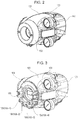
- Fig. 2 is an external perspective view of an explosion-proof device (second embodiment) including the switch structure according to the invention.
- Fig. 2 shows a positioner that controls the opening degree of a pneumatically operated control valve (valve), as an explosion-proof device.
- a positioner is obliged to have sufficient explosion-proof performance by an explosion-proof standard so as to be used in explosive gas atmospheres.
- Fig. 4 shows a block diagram of an inner configuration of this positioner 100.
- reference sign 11 denotes an I/F (interface) terminal
- 12 denotes an electric circuit module including a CPU (Central Processing Unit), a memory, etc.
- 13 denotes an electropneumatic converter
- 14 denotes a pilot relay that amplifies a nozzle back pressure P N from the electropneumatic converter 13 and supplies the amplified pressure as an output pneumatic pressure Pout to a valve 200
- 15 denotes an angle sensor that detects an operation position of the valve 200 and feeds back the detected position to the CPU of the electric circuit module 12.
- the CPU of the electric circuit module 12 receives an input electric signal I IN given from a controller 300, the CPU gives a current I1 corresponding to the input electric signal I IN to the electropneumatic converter 13.
- This current I1 is converted into the nozzle back pressure P N in the electropneumatic converter 13, and transmitted to the pilot relay 14.
- the pilot relay 14 amplifies the nozzle back pressure P N , and supplies the amplified pressure as the output pneumatic pressure Pout to the valve 200.
- the opening degree of the valve 200 that is, the process flow rate is controlled.
- the opening degree of the valve 200 is detected by the angle sensor 15, and is returned as a feedback signal I FB to the CPU of the electric circuit module 12.
- reference sign Ps denotes a supply pneumatic pressure to the electropneumatic converter 3 and the pilot relay 14.
- the pilot relay is the double-acting type, and outputs two output pneumatic pressures Pout1 and Pout2.
- the output pneumatic pressure Pout1 is set to be higher than the output pneumatic pressure Pout2.
- the output pneumatic pressure Pout2 is set to be higher than the output pneumatic pressure Pout1.
- the I/F (interface) terminal 11, the electric circuit module 12, the electropneumatic converter 13, and the angle sensor 15 are housed in the inner space of a case 101 ( Fig. 2 ). That is, the case 101 serves as an explosion-proof container (hereinafter, referred to as explosion-proof container).
- explosion-proof container The I/F (interface) terminal 11, the electric circuit module 12, the electropneumatic converter 13, and the angle sensor 15 are housed in the explosion container 101.
- a cover 102 is mounted on a front surface of the explosion-proof container 101. If the cover 102 is removed, as shown in Fig. 3 , a main cover (non-magnetic body) 104 forming part of a container wall of the explosion-proof container 101 appears.
- a switch holder 105 is fixed to the main cover 104 by a screw.
- Four push buttons 106 (106-1 to 106-4) are mounted at this switch holder 105.
- a cover 103 is mounted on a back surface of the explosion-proof container 101.
- the pilot relay 14 is provided in the space covered with the cover 103.
- Fig. 5 shows a mounting structure of the switch holder 105 and the push buttons 106 to the main cover 104.
- Fig. 5 only shows mounting portions of the push buttons 106-1 and 106-2; however the push buttons 106-3 and 106-4 are similarly mounted.
- the switch holder 105 and the push buttons 106 are formed of resin members.
- the push buttons 106 each have a columnar shape. The mounting structure is described below particularly for a single push button 106.
- the push button 106 has a columnar magnet 107 provided at a bottom portion thereof.
- the push button 106 is inserted into a mounting hole 108 provided at the switch holder 105 in a state in which the magnet 107 is arranged at the lower side.
- a compression coil spring 109 is provided in the mounting hole 108, between the bottom portion of the push button 106 and a bottom portion of the mounting hole 108.
- a first end of the compression coil spring 109 is fixed to the bottom portion of the mounting hole 108 of the switch holder 105, and a second end of the compression coil spring 109 is fixed to the bottom portion of the push button 106.
- a guide pin (first magnetic body) 110 is provided at the main cover (container wall) 104, at a position at which the guide pin 110 faces the mounting hole 108 of the switch holder 105.
- a first end surface 110a of the guide pin 110 penetrates through an upper surface (a surface facing the outside of the explosion-proof container 101) of the main cover 104, and is located at a position in a recess portion 111 formed at a bottom surface of the mounting hole 108 of the switch holder 105.
- a second end surface 110b of the guide pin 110 is located at a lower surface (a surface facing the inside of the explosion-proof container 101) of the main cover 104, and is exposed to the inside of the explosion-proof container 101.
- the end surface 110a of the guide pin 110 is located in the recess portion 111 formed at the bottom surface of the mounting hole 108 of the switch holder 105, the end surface 110a of the guide pin 110 is not exposed to the outside of the explosion-proof container 101, and hence the guide pin 110 is prevented from rusting because of the moisture etc. from the outside.
- An electrical holder (substrate holding member) 112 formed of a resin member is provided in the explosion-proof container 101.
- a main board 113 being a resin substrate is mounted at the electrical holder 112.
- a sub-guide pin (second magnetic body) 114 is provided at the electrical holder 112 at a position at which the sub-guide pin 114 faces the end surface 110b of the guide pin 110 with a gap d interposed therebetween.
- a Hall IC (magnetic sensor) 115 is provided on the main board 113, at a position at which the Hall IC 115 faces the sub-guide pin 114.
- the sub-guide pin 114 is provided at a through hole 112a formed in the electrical holder 112, in a state in which a first end surface 114a and a second end surface 114b of the sub-guide pin 114 are exposed.
- the electrical holder 112 holds the main board 113 in the explosion-proof container 101 to cause a surface of the main board 113 provided with the Hall IC 115 to face the main cover 104, and to cover the space above the Hall IC 115 provided on the main board 113.
- the sub-guide pin 114 facing the guide pin 110 and facing the Hall IC 115 is provided at the electrical holder 112.
- the main board 113 and the Hall IC 115 are covered with the electrical holder 112, and a dustproof state is kept even if the explosion-proof container 101 is open. Also, since the gap d is provided between the guide pin 110 and the sub-guide pin 114, while the magnetic flux passes through the guide pin 110 and then the sub-guide pin 114, even if an external force is applied to the explosion-proof container 101 and hence the main cover 104 is bent inward, the guide pin 110 and the sub-guide pin 114 are prevented from contacting each other and are protected from the external force.
- the electrical holder 112 covers the space above the Hall IC 115 provided on the main board 113. However, the electrical holder 112 may not cover the entire surface of the main board 113 provided with the Hall IC 115, and the electrical holder 112 may cover a partial surface including the area provided with the Hall IC 115.
- the push button 106 is returned to the original position by the urging force of the compression coil spring 109.
- the magnet 107 provided at the bottom portion of the push button 106 is moved far from the end surface 110a of the guide pin 110 provided at the main cover 104, and the Hall IC 115 no longer senses the magnetism from the magnet 107. Accordingly, the Hall IC 115 is turned OFF.
- the state of the push button 106-1 shown in Fig. 5 indicates this state.
- the push button 106, the magnet 107, the compression coil spring 109, the guide pin 110, the sub-guide pin 114, and the Hall IC 115 configure a magnetic switch SW.
- a distance L between adjacent magnetic switches SW is 20 mm
- a distance H between a lower surface of the magnet 107 and an upper surface of the Hall IC 115 when the push button 106 is pushed is 30 mm
- a gap d between the guide pin 110 and the sub-guide pin 114 is about 1 to 2 mm.
- the end surface 110a of the guide pin 110 is located in the recess portion 111 formed at the bottom surface of the mounting hole 108 of the switch holder 105; however, the end surface 110a of the guide pin 110 may be embedded in the middle of the main cover 104 without being exposed from the main cover (container wall) 104. Also, the end surface 110b of the guide pin 110 may be embedded in the middle of the main cover 104 without being exposed from the main cover (container wall) 104.
- the first end surface 114a and the second end surface 114b of the sub-guide pin 114 provided at the electrical holder 112 are exposed from the electrical holder 112; however, the end surface 114a or 114b of the sub-guide pin 114 may not be exposed from the electrical holder 112. That is, both or one of the end surfaces 114a and 114b of the sub-guide pin 114 may be embedded in the middle of the electrical holder 112 without being exposed from the electrical holder 112.
- the end surface 114b of the sub-guide pin 114 may be brought into contact with the Hall IC 115 provided on the main board 113.
- the end surface 114b may have a gap with respect to the Hall IC 115 without contacting the Hall IC 115.
- the example is described in which the explosion-proof device is applied to the positioner and the switch structure according to the invention is applied to this positioner.
- an explosion-proof device such as a pressure transmitter or an electromagnetic flowmeter, may use the switch structure according to the invention.
- the magnetic body 4 according to the first embodiment and the guide pin 110 and the sub-guide pin 114 according to the second embodiment are desirably formed of a ferromagnetic body such as a permalloy.
- the guide pin 110 and the sub-guide pin 114 may be formed of the same material, and may be formed of different materials.
- the invention can be used for various devices each turning ON/OFF a magnetic sensor in a hermetically sealed container, such as a positioner that controls the opening degree of a pneumatically operated control valve.
Landscapes
- Switches That Are Operated By Magnetic Or Electric Fields (AREA)
- Measuring Magnetic Variables (AREA)
Applications Claiming Priority (2)
| Application Number | Priority Date | Filing Date | Title |
|---|---|---|---|
| JP2013223919 | 2013-10-29 | ||
| PCT/JP2014/078708 WO2015064610A1 (ja) | 2013-10-29 | 2014-10-29 | スイッチ構造および防爆機器 |
Publications (3)
| Publication Number | Publication Date |
|---|---|
| EP3065155A1 true EP3065155A1 (de) | 2016-09-07 |
| EP3065155A4 EP3065155A4 (de) | 2017-07-12 |
| EP3065155B1 EP3065155B1 (de) | 2021-01-06 |
Family
ID=53004211
Family Applications (1)
| Application Number | Title | Priority Date | Filing Date |
|---|---|---|---|
| EP14858052.5A Active EP3065155B1 (de) | 2013-10-29 | 2014-10-29 | Schaltstruktur und explosionsgeschützte vorrichtung |
Country Status (5)
| Country | Link |
|---|---|
| US (1) | US9754739B2 (de) |
| EP (1) | EP3065155B1 (de) |
| JP (1) | JP6317661B2 (de) |
| CN (1) | CN105723490B (de) |
| WO (1) | WO2015064610A1 (de) |
Cited By (1)
| Publication number | Priority date | Publication date | Assignee | Title |
|---|---|---|---|---|
| ITUA20163879A1 (it) * | 2016-05-27 | 2017-11-27 | Andrea Paone | Tastiera per comando elettrico a distanza via cavo antideflagrante |
Families Citing this family (11)
| Publication number | Priority date | Publication date | Assignee | Title |
|---|---|---|---|---|
| JP6086874B2 (ja) * | 2014-01-27 | 2017-03-01 | アズビル株式会社 | スイッチ構造および防爆機器 |
| US10372021B2 (en) * | 2014-12-31 | 2019-08-06 | Anthony S Lenzo | Triple axis magnetic actuator through non-metallic substrate |
| CN106486899A (zh) * | 2015-09-02 | 2017-03-08 | 费希尔控制国际公司 | 用于具有环境保护的壳体的开关设备 |
| US11239015B2 (en) | 2015-09-28 | 2022-02-01 | Eaton Intelligent Power Limited | Magnetic controls for industrial enclosures |
| US10312908B2 (en) * | 2015-09-28 | 2019-06-04 | Eaton Intelligent Power Limited | Nested magnetic controls for industrial enclosures |
| CN108489514B (zh) * | 2018-03-19 | 2021-12-14 | 中国船舶重工集团公司第七0四研究所 | 单侧横向地磁模拟线圈测量感应磁场Ziy的方法 |
| IT201800005373A1 (it) * | 2018-05-15 | 2019-11-15 | Dispositivo attuatore per il passaggio di stato di una apparecchiatura a controllo elettronico ad uso subacqueo e relativo sistema | |
| US11094486B2 (en) | 2018-12-20 | 2021-08-17 | Cognex Corporation | Magnetic trigger arrangement |
| US11657992B2 (en) | 2019-05-06 | 2023-05-23 | Jeffrey A. Stallmer | Protective cover assembly for magnetically actuating an electrical wall switch |
| US11769643B2 (en) * | 2021-08-17 | 2023-09-26 | Eagle Technology, Llc | Underwater device with rotary switch and related switch assembly and method |
| JP2024129621A (ja) * | 2023-03-13 | 2024-09-27 | オムロン株式会社 | スイッチ |
Family Cites Families (13)
| Publication number | Priority date | Publication date | Assignee | Title |
|---|---|---|---|---|
| FR2233632A1 (en) * | 1973-06-18 | 1975-01-10 | Ibm | Magnetoelectric transducer unit - has Hall element, and detects magnetic field changes produced by ferromagnetic element |
| US4152755A (en) * | 1977-06-20 | 1979-05-01 | Nixt Richard E | Portable magnetically actuatable flashlight |
| JPS5462073U (de) * | 1977-10-11 | 1979-05-01 | ||
| JPS57150422U (de) * | 1981-03-17 | 1982-09-21 | ||
| DE3853076T2 (de) | 1987-10-22 | 1995-09-28 | Rosemount Inc | Sender mit magnetischem null/vollskala-stellglied. |
| JPH03127743U (de) * | 1990-04-07 | 1991-12-24 | ||
| US5369386A (en) * | 1992-11-13 | 1994-11-29 | Elsag International B.V. | Removable magnetic zero/span actuator for a transmitter |
| US6246305B1 (en) * | 1998-12-30 | 2001-06-12 | Honeywell International Inc | Apparatus and method for operating a micromechanical switch |
| DE10245952A1 (de) * | 2002-10-02 | 2004-04-15 | Hilti Ag | Elektromodul mit schlagwettergeschütztem Schalter |
| JP2004146105A (ja) * | 2002-10-22 | 2004-05-20 | Oval Corp | スイッチ機構及びそれを備えた機器 |
| US7256671B1 (en) * | 2003-04-24 | 2007-08-14 | Brian Preaux | Portable light system having a sealed switch |
| JP2009252732A (ja) * | 2008-04-03 | 2009-10-29 | Nisshin Erekkusu:Kk | スイッチ |
| CN201812740U (zh) * | 2010-10-14 | 2011-04-27 | 惠州市厨易智能科技有限公司 | 一种磁性按钮 |
-
2014
- 2014-10-29 WO PCT/JP2014/078708 patent/WO2015064610A1/ja not_active Ceased
- 2014-10-29 CN CN201480059514.2A patent/CN105723490B/zh active Active
- 2014-10-29 EP EP14858052.5A patent/EP3065155B1/de active Active
- 2014-10-29 JP JP2014219937A patent/JP6317661B2/ja active Active
-
2016
- 2016-04-26 US US15/139,131 patent/US9754739B2/en active Active
Cited By (2)
| Publication number | Priority date | Publication date | Assignee | Title |
|---|---|---|---|---|
| ITUA20163879A1 (it) * | 2016-05-27 | 2017-11-27 | Andrea Paone | Tastiera per comando elettrico a distanza via cavo antideflagrante |
| EP3249672A1 (de) * | 2016-05-27 | 2017-11-29 | Andrea Paone | Explosionsgeschützte druckknopftafel für fernbedienung über kabel |
Also Published As
| Publication number | Publication date |
|---|---|
| US9754739B2 (en) | 2017-09-05 |
| EP3065155A4 (de) | 2017-07-12 |
| CN105723490A (zh) | 2016-06-29 |
| CN105723490B (zh) | 2019-01-08 |
| JP2015111562A (ja) | 2015-06-18 |
| WO2015064610A1 (ja) | 2015-05-07 |
| JP6317661B2 (ja) | 2018-04-25 |
| EP3065155B1 (de) | 2021-01-06 |
| US20160240331A1 (en) | 2016-08-18 |
Similar Documents
| Publication | Publication Date | Title |
|---|---|---|
| EP3065155B1 (de) | Schaltstruktur und explosionsgeschützte vorrichtung | |
| ES3025191T3 (en) | Magnetic coupling device with at least one of a sensor arrangement and a degauss capability | |
| US20080224803A1 (en) | Switch | |
| EP3171384A1 (de) | Elektromagnetischer schalter und verfahren zur anpassung der kontaktposition dafür | |
| US20180373351A1 (en) | Input device, and input system employing same | |
| JP2016057292A (ja) | ノギスジョウ取付式マグネットアクセサリ | |
| US10982793B2 (en) | Valve control head | |
| ATE426944T1 (de) | Elekromagnetisches zuhaltesystem eines sicherheitsschalters | |
| US10823584B2 (en) | Intelligent device having detachable bodies | |
| US20190079585A1 (en) | Electromagnetic Feedback Actuator for an Operating Element and Arrangement Having at Least One Electromagnetic Feedback Actuator | |
| US11088690B2 (en) | Switch | |
| US20100097050A1 (en) | Displacement measuring apparatus | |
| CN110968186A (zh) | 提供力感测和/或触觉输出的按钮 | |
| JP2010153199A (ja) | 多方向入力装置 | |
| KR20200059923A (ko) | 안테나를 포함하는 디지털 펜의 구조 | |
| KR20140144925A (ko) | 압력 센서 패키지 및 압력 센서 패키지가 구비된 위치 지시기 | |
| EP1751781B1 (de) | Magnet-schalter-anordnung | |
| JP6086874B2 (ja) | スイッチ構造および防爆機器 | |
| JP3805291B2 (ja) | 弁位置検出スイッチ付パイロット形切換弁 | |
| MX2016010157A (es) | Circuito de sensor magnetico integrado y conjunto de motor. | |
| CN111316394B (zh) | 开关 | |
| JP2016099160A (ja) | 電流センサ | |
| EP3550411A1 (de) | Berührungssensor zur verhinderung von falscherkennung und elektronische vorrichtung damit | |
| US20240029982A1 (en) | Electromagnetic relay | |
| CN110517929B (zh) | 一种金属传感器开关 |
Legal Events
| Date | Code | Title | Description |
|---|---|---|---|
| PUAI | Public reference made under article 153(3) epc to a published international application that has entered the european phase |
Free format text: ORIGINAL CODE: 0009012 |
|
| 17P | Request for examination filed |
Effective date: 20160428 |
|
| AK | Designated contracting states |
Kind code of ref document: A1 Designated state(s): AL AT BE BG CH CY CZ DE DK EE ES FI FR GB GR HR HU IE IS IT LI LT LU LV MC MK MT NL NO PL PT RO RS SE SI SK SM TR |
|
| AX | Request for extension of the european patent |
Extension state: BA ME |
|
| DAX | Request for extension of the european patent (deleted) | ||
| A4 | Supplementary search report drawn up and despatched |
Effective date: 20170613 |
|
| RIC1 | Information provided on ipc code assigned before grant |
Ipc: H01H 36/00 20060101AFI20170606BHEP Ipc: H03K 17/97 20060101ALI20170606BHEP Ipc: H01H 9/04 20060101ALI20170606BHEP |
|
| GRAP | Despatch of communication of intention to grant a patent |
Free format text: ORIGINAL CODE: EPIDOSNIGR1 |
|
| STAA | Information on the status of an ep patent application or granted ep patent |
Free format text: STATUS: GRANT OF PATENT IS INTENDED |
|
| INTG | Intention to grant announced |
Effective date: 20200716 |
|
| GRAS | Grant fee paid |
Free format text: ORIGINAL CODE: EPIDOSNIGR3 |
|
| GRAA | (expected) grant |
Free format text: ORIGINAL CODE: 0009210 |
|
| STAA | Information on the status of an ep patent application or granted ep patent |
Free format text: STATUS: THE PATENT HAS BEEN GRANTED |
|
| AK | Designated contracting states |
Kind code of ref document: B1 Designated state(s): AL AT BE BG CH CY CZ DE DK EE ES FI FR GB GR HR HU IE IS IT LI LT LU LV MC MK MT NL NO PL PT RO RS SE SI SK SM TR |
|
| REG | Reference to a national code |
Ref country code: GB Ref legal event code: FG4D |
|
| REG | Reference to a national code |
Ref country code: AT Ref legal event code: REF Ref document number: 1353264 Country of ref document: AT Kind code of ref document: T Effective date: 20210115 Ref country code: CH Ref legal event code: EP |
|
| REG | Reference to a national code |
Ref country code: DE Ref legal event code: R096 Ref document number: 602014074083 Country of ref document: DE |
|
| REG | Reference to a national code |
Ref country code: IE Ref legal event code: FG4D |
|
| REG | Reference to a national code |
Ref country code: NL Ref legal event code: MP Effective date: 20210106 |
|
| REG | Reference to a national code |
Ref country code: AT Ref legal event code: MK05 Ref document number: 1353264 Country of ref document: AT Kind code of ref document: T Effective date: 20210106 |
|
| REG | Reference to a national code |
Ref country code: LT Ref legal event code: MG9D |
|
| PG25 | Lapsed in a contracting state [announced via postgrant information from national office to epo] |
Ref country code: BG Free format text: LAPSE BECAUSE OF FAILURE TO SUBMIT A TRANSLATION OF THE DESCRIPTION OR TO PAY THE FEE WITHIN THE PRESCRIBED TIME-LIMIT Effective date: 20210406 Ref country code: NO Free format text: LAPSE BECAUSE OF FAILURE TO SUBMIT A TRANSLATION OF THE DESCRIPTION OR TO PAY THE FEE WITHIN THE PRESCRIBED TIME-LIMIT Effective date: 20210406 Ref country code: NL Free format text: LAPSE BECAUSE OF FAILURE TO SUBMIT A TRANSLATION OF THE DESCRIPTION OR TO PAY THE FEE WITHIN THE PRESCRIBED TIME-LIMIT Effective date: 20210106 Ref country code: HR Free format text: LAPSE BECAUSE OF FAILURE TO SUBMIT A TRANSLATION OF THE DESCRIPTION OR TO PAY THE FEE WITHIN THE PRESCRIBED TIME-LIMIT Effective date: 20210106 Ref country code: FI Free format text: LAPSE BECAUSE OF FAILURE TO SUBMIT A TRANSLATION OF THE DESCRIPTION OR TO PAY THE FEE WITHIN THE PRESCRIBED TIME-LIMIT Effective date: 20210106 Ref country code: GR Free format text: LAPSE BECAUSE OF FAILURE TO SUBMIT A TRANSLATION OF THE DESCRIPTION OR TO PAY THE FEE WITHIN THE PRESCRIBED TIME-LIMIT Effective date: 20210407 Ref country code: PT Free format text: LAPSE BECAUSE OF FAILURE TO SUBMIT A TRANSLATION OF THE DESCRIPTION OR TO PAY THE FEE WITHIN THE PRESCRIBED TIME-LIMIT Effective date: 20210506 Ref country code: LT Free format text: LAPSE BECAUSE OF FAILURE TO SUBMIT A TRANSLATION OF THE DESCRIPTION OR TO PAY THE FEE WITHIN THE PRESCRIBED TIME-LIMIT Effective date: 20210106 |
|
| PG25 | Lapsed in a contracting state [announced via postgrant information from national office to epo] |
Ref country code: SE Free format text: LAPSE BECAUSE OF FAILURE TO SUBMIT A TRANSLATION OF THE DESCRIPTION OR TO PAY THE FEE WITHIN THE PRESCRIBED TIME-LIMIT Effective date: 20210106 Ref country code: LV Free format text: LAPSE BECAUSE OF FAILURE TO SUBMIT A TRANSLATION OF THE DESCRIPTION OR TO PAY THE FEE WITHIN THE PRESCRIBED TIME-LIMIT Effective date: 20210106 Ref country code: PL Free format text: LAPSE BECAUSE OF FAILURE TO SUBMIT A TRANSLATION OF THE DESCRIPTION OR TO PAY THE FEE WITHIN THE PRESCRIBED TIME-LIMIT Effective date: 20210106 Ref country code: RS Free format text: LAPSE BECAUSE OF FAILURE TO SUBMIT A TRANSLATION OF THE DESCRIPTION OR TO PAY THE FEE WITHIN THE PRESCRIBED TIME-LIMIT Effective date: 20210106 Ref country code: AT Free format text: LAPSE BECAUSE OF FAILURE TO SUBMIT A TRANSLATION OF THE DESCRIPTION OR TO PAY THE FEE WITHIN THE PRESCRIBED TIME-LIMIT Effective date: 20210106 |
|
| PG25 | Lapsed in a contracting state [announced via postgrant information from national office to epo] |
Ref country code: IS Free format text: LAPSE BECAUSE OF FAILURE TO SUBMIT A TRANSLATION OF THE DESCRIPTION OR TO PAY THE FEE WITHIN THE PRESCRIBED TIME-LIMIT Effective date: 20210506 |
|
| REG | Reference to a national code |
Ref country code: DE Ref legal event code: R097 Ref document number: 602014074083 Country of ref document: DE |
|
| PG25 | Lapsed in a contracting state [announced via postgrant information from national office to epo] |
Ref country code: CZ Free format text: LAPSE BECAUSE OF FAILURE TO SUBMIT A TRANSLATION OF THE DESCRIPTION OR TO PAY THE FEE WITHIN THE PRESCRIBED TIME-LIMIT Effective date: 20210106 Ref country code: EE Free format text: LAPSE BECAUSE OF FAILURE TO SUBMIT A TRANSLATION OF THE DESCRIPTION OR TO PAY THE FEE WITHIN THE PRESCRIBED TIME-LIMIT Effective date: 20210106 Ref country code: SM Free format text: LAPSE BECAUSE OF FAILURE TO SUBMIT A TRANSLATION OF THE DESCRIPTION OR TO PAY THE FEE WITHIN THE PRESCRIBED TIME-LIMIT Effective date: 20210106 |
|
| PLBE | No opposition filed within time limit |
Free format text: ORIGINAL CODE: 0009261 |
|
| STAA | Information on the status of an ep patent application or granted ep patent |
Free format text: STATUS: NO OPPOSITION FILED WITHIN TIME LIMIT |
|
| PG25 | Lapsed in a contracting state [announced via postgrant information from national office to epo] |
Ref country code: DK Free format text: LAPSE BECAUSE OF FAILURE TO SUBMIT A TRANSLATION OF THE DESCRIPTION OR TO PAY THE FEE WITHIN THE PRESCRIBED TIME-LIMIT Effective date: 20210106 Ref country code: ES Free format text: LAPSE BECAUSE OF FAILURE TO SUBMIT A TRANSLATION OF THE DESCRIPTION OR TO PAY THE FEE WITHIN THE PRESCRIBED TIME-LIMIT Effective date: 20210106 Ref country code: SK Free format text: LAPSE BECAUSE OF FAILURE TO SUBMIT A TRANSLATION OF THE DESCRIPTION OR TO PAY THE FEE WITHIN THE PRESCRIBED TIME-LIMIT Effective date: 20210106 Ref country code: RO Free format text: LAPSE BECAUSE OF FAILURE TO SUBMIT A TRANSLATION OF THE DESCRIPTION OR TO PAY THE FEE WITHIN THE PRESCRIBED TIME-LIMIT Effective date: 20210106 |
|
| 26N | No opposition filed |
Effective date: 20211007 |
|
| PG25 | Lapsed in a contracting state [announced via postgrant information from national office to epo] |
Ref country code: AL Free format text: LAPSE BECAUSE OF FAILURE TO SUBMIT A TRANSLATION OF THE DESCRIPTION OR TO PAY THE FEE WITHIN THE PRESCRIBED TIME-LIMIT Effective date: 20210106 |
|
| PG25 | Lapsed in a contracting state [announced via postgrant information from national office to epo] |
Ref country code: SI Free format text: LAPSE BECAUSE OF FAILURE TO SUBMIT A TRANSLATION OF THE DESCRIPTION OR TO PAY THE FEE WITHIN THE PRESCRIBED TIME-LIMIT Effective date: 20210106 |
|
| PG25 | Lapsed in a contracting state [announced via postgrant information from national office to epo] |
Ref country code: IT Free format text: LAPSE BECAUSE OF FAILURE TO SUBMIT A TRANSLATION OF THE DESCRIPTION OR TO PAY THE FEE WITHIN THE PRESCRIBED TIME-LIMIT Effective date: 20210106 |
|
| REG | Reference to a national code |
Ref country code: CH Ref legal event code: PL |
|
| PG25 | Lapsed in a contracting state [announced via postgrant information from national office to epo] |
Ref country code: IS Free format text: LAPSE BECAUSE OF FAILURE TO SUBMIT A TRANSLATION OF THE DESCRIPTION OR TO PAY THE FEE WITHIN THE PRESCRIBED TIME-LIMIT Effective date: 20210506 |
|
| REG | Reference to a national code |
Ref country code: BE Ref legal event code: MM Effective date: 20211031 |
|
| GBPC | Gb: european patent ceased through non-payment of renewal fee |
Effective date: 20211029 |
|
| PG25 | Lapsed in a contracting state [announced via postgrant information from national office to epo] |
Ref country code: MC Free format text: LAPSE BECAUSE OF FAILURE TO SUBMIT A TRANSLATION OF THE DESCRIPTION OR TO PAY THE FEE WITHIN THE PRESCRIBED TIME-LIMIT Effective date: 20210106 |
|
| PG25 | Lapsed in a contracting state [announced via postgrant information from national office to epo] |
Ref country code: LU Free format text: LAPSE BECAUSE OF NON-PAYMENT OF DUE FEES Effective date: 20211029 Ref country code: GB Free format text: LAPSE BECAUSE OF NON-PAYMENT OF DUE FEES Effective date: 20211029 Ref country code: BE Free format text: LAPSE BECAUSE OF NON-PAYMENT OF DUE FEES Effective date: 20211031 |
|
| PG25 | Lapsed in a contracting state [announced via postgrant information from national office to epo] |
Ref country code: LI Free format text: LAPSE BECAUSE OF NON-PAYMENT OF DUE FEES Effective date: 20211031 Ref country code: CH Free format text: LAPSE BECAUSE OF NON-PAYMENT OF DUE FEES Effective date: 20211031 |
|
| PG25 | Lapsed in a contracting state [announced via postgrant information from national office to epo] |
Ref country code: FR Free format text: LAPSE BECAUSE OF NON-PAYMENT OF DUE FEES Effective date: 20211031 |
|
| PG25 | Lapsed in a contracting state [announced via postgrant information from national office to epo] |
Ref country code: IE Free format text: LAPSE BECAUSE OF NON-PAYMENT OF DUE FEES Effective date: 20211029 |
|
| PG25 | Lapsed in a contracting state [announced via postgrant information from national office to epo] |
Ref country code: HU Free format text: LAPSE BECAUSE OF FAILURE TO SUBMIT A TRANSLATION OF THE DESCRIPTION OR TO PAY THE FEE WITHIN THE PRESCRIBED TIME-LIMIT; INVALID AB INITIO Effective date: 20141029 |
|
| PG25 | Lapsed in a contracting state [announced via postgrant information from national office to epo] |
Ref country code: CY Free format text: LAPSE BECAUSE OF FAILURE TO SUBMIT A TRANSLATION OF THE DESCRIPTION OR TO PAY THE FEE WITHIN THE PRESCRIBED TIME-LIMIT Effective date: 20210106 |
|
| PG25 | Lapsed in a contracting state [announced via postgrant information from national office to epo] |
Ref country code: MK Free format text: LAPSE BECAUSE OF FAILURE TO SUBMIT A TRANSLATION OF THE DESCRIPTION OR TO PAY THE FEE WITHIN THE PRESCRIBED TIME-LIMIT Effective date: 20210106 |
|
| PG25 | Lapsed in a contracting state [announced via postgrant information from national office to epo] |
Ref country code: MT Free format text: LAPSE BECAUSE OF FAILURE TO SUBMIT A TRANSLATION OF THE DESCRIPTION OR TO PAY THE FEE WITHIN THE PRESCRIBED TIME-LIMIT Effective date: 20210106 |
|
| PG25 | Lapsed in a contracting state [announced via postgrant information from national office to epo] |
Ref country code: TR Free format text: LAPSE BECAUSE OF FAILURE TO SUBMIT A TRANSLATION OF THE DESCRIPTION OR TO PAY THE FEE WITHIN THE PRESCRIBED TIME-LIMIT Effective date: 20210106 |
|
| PGFP | Annual fee paid to national office [announced via postgrant information from national office to epo] |
Ref country code: DE Payment date: 20250902 Year of fee payment: 12 |