EP3065210A1 - Mécanisme permettant de manipuler des capsules contenant un combustible pour des piles à combustible - Google Patents
Mécanisme permettant de manipuler des capsules contenant un combustible pour des piles à combustible Download PDFInfo
- Publication number
- EP3065210A1 EP3065210A1 EP15382098.0A EP15382098A EP3065210A1 EP 3065210 A1 EP3065210 A1 EP 3065210A1 EP 15382098 A EP15382098 A EP 15382098A EP 3065210 A1 EP3065210 A1 EP 3065210A1
- Authority
- EP
- European Patent Office
- Prior art keywords
- capsules
- transporter
- fuel
- capsule
- mechanism according
- Prior art date
- Legal status (The legal status is an assumption and is not a legal conclusion. Google has not performed a legal analysis and makes no representation as to the accuracy of the status listed.)
- Withdrawn
Links
- 239000002775 capsule Substances 0.000 title claims abstract description 153
- 239000000446 fuel Substances 0.000 title claims abstract description 59
- 230000007246 mechanism Effects 0.000 title claims abstract description 28
- 238000000605 extraction Methods 0.000 claims description 25
- 230000000694 effects Effects 0.000 claims description 9
- 238000010438 heat treatment Methods 0.000 claims description 8
- 238000003780 insertion Methods 0.000 claims description 8
- 230000037431 insertion Effects 0.000 claims description 8
- 238000006073 displacement reaction Methods 0.000 claims description 5
- 230000002093 peripheral effect Effects 0.000 claims description 5
- 230000005540 biological transmission Effects 0.000 claims description 3
- 230000006698 induction Effects 0.000 claims description 3
- 210000004027 cell Anatomy 0.000 description 29
- 238000000429 assembly Methods 0.000 description 3
- 230000000712 assembly Effects 0.000 description 3
- 238000000034 method Methods 0.000 description 3
- 230000001133 acceleration Effects 0.000 description 2
- 230000008859 change Effects 0.000 description 2
- 238000011161 development Methods 0.000 description 2
- 230000018109 developmental process Effects 0.000 description 2
- 239000012528 membrane Substances 0.000 description 2
- 230000032258 transport Effects 0.000 description 2
- 230000015572 biosynthetic process Effects 0.000 description 1
- 210000001520 comb Anatomy 0.000 description 1
- 150000001875 compounds Chemical class 0.000 description 1
- 239000000356 contaminant Substances 0.000 description 1
- 125000004122 cyclic group Chemical group 0.000 description 1
- 238000000151 deposition Methods 0.000 description 1
- 238000013461 design Methods 0.000 description 1
- 238000010586 diagram Methods 0.000 description 1
- 239000007789 gas Substances 0.000 description 1
- 230000006872 improvement Effects 0.000 description 1
- 238000009434 installation Methods 0.000 description 1
- 238000012423 maintenance Methods 0.000 description 1
- 238000012986 modification Methods 0.000 description 1
- 230000004048 modification Effects 0.000 description 1
- 238000012544 monitoring process Methods 0.000 description 1
- 230000008569 process Effects 0.000 description 1
- 210000003370 receptor cell Anatomy 0.000 description 1
- 230000001360 synchronised effect Effects 0.000 description 1
Images




Classifications
-
- H—ELECTRICITY
- H01—ELECTRIC ELEMENTS
- H01M—PROCESSES OR MEANS, e.g. BATTERIES, FOR THE DIRECT CONVERSION OF CHEMICAL ENERGY INTO ELECTRICAL ENERGY
- H01M8/00—Fuel cells; Manufacture thereof
- H01M8/04—Auxiliary arrangements, e.g. for control of pressure or for circulation of fluids
- H01M8/04082—Arrangements for control of reactant parameters, e.g. pressure or concentration
- H01M8/04201—Reactant storage and supply, e.g. means for feeding, pipes
-
- A—HUMAN NECESSITIES
- A47—FURNITURE; DOMESTIC ARTICLES OR APPLIANCES; COFFEE MILLS; SPICE MILLS; SUCTION CLEANERS IN GENERAL
- A47F—SPECIAL FURNITURE, FITTINGS, OR ACCESSORIES FOR SHOPS, STOREHOUSES, BARS, RESTAURANTS OR THE LIKE; PAYING COUNTERS
- A47F1/00—Racks for dispensing merchandise; Containers for dispensing merchandise
- A47F1/04—Racks or containers with arrangements for dispensing articles, e.g. by means of gravity or springs
- A47F1/08—Racks or containers with arrangements for dispensing articles, e.g. by means of gravity or springs dispensing from bottom
- A47F1/087—Racks or containers with arrangements for dispensing articles, e.g. by means of gravity or springs dispensing from bottom the container having approximately horizontal tracks of the serpentine type
-
- H—ELECTRICITY
- H01—ELECTRIC ELEMENTS
- H01M—PROCESSES OR MEANS, e.g. BATTERIES, FOR THE DIRECT CONVERSION OF CHEMICAL ENERGY INTO ELECTRICAL ENERGY
- H01M8/00—Fuel cells; Manufacture thereof
- H01M8/04—Auxiliary arrangements, e.g. for control of pressure or for circulation of fluids
- H01M8/04082—Arrangements for control of reactant parameters, e.g. pressure or concentration
- H01M8/04201—Reactant storage and supply, e.g. means for feeding, pipes
- H01M8/04208—Cartridges, cryogenic media or cryogenic reservoirs
-
- Y—GENERAL TAGGING OF NEW TECHNOLOGICAL DEVELOPMENTS; GENERAL TAGGING OF CROSS-SECTIONAL TECHNOLOGIES SPANNING OVER SEVERAL SECTIONS OF THE IPC; TECHNICAL SUBJECTS COVERED BY FORMER USPC CROSS-REFERENCE ART COLLECTIONS [XRACs] AND DIGESTS
- Y02—TECHNOLOGIES OR APPLICATIONS FOR MITIGATION OR ADAPTATION AGAINST CLIMATE CHANGE
- Y02E—REDUCTION OF GREENHOUSE GAS [GHG] EMISSIONS, RELATED TO ENERGY GENERATION, TRANSMISSION OR DISTRIBUTION
- Y02E60/00—Enabling technologies; Technologies with a potential or indirect contribution to GHG emissions mitigation
- Y02E60/30—Hydrogen technology
- Y02E60/50—Fuel cells
Definitions
- the present invention relates to a mechanism for handling capsules containing fuel for fuel cells and more specifically for storing, transporting, inserting and extracting cylindrical capsules of chemical compounds for supplying fuel to fuel cells.
- the invention is in particular aimed at covering the need for the flow of capsules in fuel cells for the aeronautical sector.
- Fuel cells have had a strong boost thanks to their application in the automotive industry, with the commercializing of the electric car. But from all of the application attributed to fuel cells, the use in aviation seems to be one of the most promising. Companies in the sector all over the world are currently working on exclusive developments for using fuel cells as an alternative to the traditional APU (auxiliary power unit) based on turbo machines, both in commercial airplanes and in UAV (unmanned aerial vehicles).
- APU auxiliary power unit
- turbo machines both in commercial airplanes and in UAV (unmanned aerial vehicles).
- US7979974 may be cited as background, which describes a system and method for placing the assemblies and membrane electrodes sequentially within fuel cells, using a system which collects the membranes and separating plates from two storage boxes and transports them by means of a transport belt until placing them in groups in order to complete each one of the cells.
- EP0493918B1 may be cited, which describes a system for loading and transporting by means of a transporter belt and an oscillating mechanism for collecting capsules for a howitzer, where the transporter belt is formed by the fastening pieces of the capsules per se, which are closed, which complicates the collection and release of said capsules.
- the object of the present invention is a mechanism intended for the cyclic feeding of a fuel cell system, proceeding from capsules containing fuel.
- the mechanism of the invention comprises: an interchangeable storage box for container capsules, which has an internal rail in the form of a flat coil for the capsules, which runs between an inlet port and an outlet port of the box; a capsule transporter which runs through the exterior of the storage box between the outlet and inlet ports of said box and has receptor cells for the capsules; a device for inserting capsules in the cells of the transporter, arranged between the outlet port of the storage box and the transporter belt; a chamber for extracting fuel contained in the capsules, alignable with a position of the cells of the capsule transporter, being fuel-tight by means of an inflatable seal, and a heating system; and a pusher device responsible for displacing the capsule housed in the cell facing said chamber up to the fuel extraction chamber.
- the mechanism of the invention has two different parts, which in combination form a closed circuit.
- the first of these parts consists of the box, for example in the form of a prism, for storing and dispensing capsules, having a tubular structure.
- a mechanism replaces the box when necessary, as a function of the fuel available in the box.
- Each one of these boxes contains an undulating rail in the form of a flat coil with the geometry suitable for avoiding capsules getting stuck and incorrect installation of the same.
- the circulation undulating rail is defined by a passage with a transverse section approximately equal to the diametric section of the capsules, the passage of which defines an undulating circuit between the inlet and outlet ports of the storage box.
- the number of capsules contained in each box may be between 10 and 50.
- each box contains a fixed idle capsule without a load, which the device recognizes as an indicator for the position of the last loaded capsule, and therefore determines the need to change the box.
- the unload box is changed for a full box, used capsules will continue to be in the transporter that are inserted into the new box in order to push the full capsules and continue the supply.
- the second part of the mechanism consists of the capsule transporter, the device for inserting capsules in the cells of the transporter, the fuel extraction chamber and the pusher-extractor device. This second part is connected to the storage box such that as a unit they form a closed circulation circuit of loaded and unloaded capsules.
- the capsule transporter runs between the outlet and inlet ports of the capsule box and consists of one, two or more parallel and coplanar transporter belts that are mounted on a series of rollers and carry battlements from which recipient cells for capsules are determined.
- the capsule transporter collects the capsules that the capsule insertion device deposits on the transporter and transfers them firstly aligned with the extraction chamber and subsequently to the inlet port of the box, where they are reinserted.
- the battlements constitute the fastening elements of the capsules without external drive.
- the fastening and release of capsules is controlled with the curvature of the rollers on which are mounted the belts and with the fixing position and angle of the battlements to the belt.
- the battlements are arranged on the belt or belts in transversal alignments, between two consecutive alignments a cell for receiving a capsule is delimited.
- each transversal alignment is preferably fixed on the transporter belt or belts by way of points that are slightly out of phase with each other along the belts.
- the device for inserting capsules in the cells of the transporter consists of a curved shovel that is arranged between the outlet port of the storage box and the transporter.
- This shovel is mounted on a shaft that is perpendicular to the direction of displacement of said transporter and is connected to one of the rollers on which the belts are mounted by means of a transmission system and an assembly of levers that define an articulated quadrilateral. All of which to cause the tilting of the shovel between a position for receiving capsules, in which the concave side of the shovel is directed towards the outlet port of the storage box and a discharge position in which the concavity of the shovel is directed towards the cell facing the transporter, while the convexity is directed towards the outlet port of the storage box.
- the insertion device introduces the capsules in the belt of the capsule transporter, while avoiding undesired movements of the capsules in the box.
- the fuel extraction chamber has a transverse section approximately equal to that of the capsules containing fuel, but not as long as said capsules.
- This chamber is open at the base adjacent to the transporter belt and closed by the opposing base.
- the chamber has one inflatable internal peripheral seal, adjacent to the open base and a fuel outlet hole in the closed base. On the internal surface of this closed base is arranged a fuel-tight seal which surrounds the fuel outlet hole.
- the chamber includes a peripheral heating element close to the closed base
- the fuel extraction chamber consists of two coaxial walls, one internal and another external, between which is arranged the heating element, which can operate by induction, in which case the internal wall is thermally insulating, or by the Joule effect, in which case the internal wall is thermally conductive.
- the external wall is mechanically resistant.
- the fuel extraction stage may be one-off or may take place a number of times, as a function of the quantity of fuel which needs to be released.
- the chamber must guarantee the strictest water-tightness in order to avoid fuel leaks. Due to the fact that common fuel-tight seals are worn with the constant friction of the entrance and exit of the capsules, in accordance with the invention, a seal is used which does not rub against the capsules, during their entrance to and exit from the chamber; an inflatable seal can for example be used, operated by means of pneumatic equipment.
- a clamp In order to move the capsule from the belt to the extractor stage, a clamp is used which is inserted in the latter.
- the axial movement of this clamp is achieved by means of an actuator.
- the clamp grips the capsules automatically upon entering into contact with it, it inserts the capsule and maintains it under pressure against the fuel extraction chamber until the capsule is consumed and then the actuator is retracted and releases the capsule when the clamp encounters a stop installed for such purpose, re-depositing the capsule on the transporter.
- the pusher device consists of a linear actuator that is arranged in alignment to or parallel with the fuel extraction chamber, close to the capsule transporter, on the opposing side to that occupied by said fuel extraction chamber, with respect to the transporter.
- This linear actuator carries, at the internal end, a clamp, the closing and opening of which is caused by the effect of its pushing against the capsule, and against fixed stops located at the end of the extraction route.
- the machine of the invention consists of an interchangeable box or container (1) of capsules containing fuel, within which is mounted a rail (2), with an undulating trajectory, on which the capsules circulate between an inlet port (3) and an outlet port (4) for capsules.
- the machine includes one or more chambers (5), where the release or extraction of the fuel from the container capsules takes place, up to which said capsules are transported by means of a transporter (6) which runs outside the box (1) from the outlet port (4) to the inlet port (3) passing through the chamber (5) where the capsules are introduced and extracted by means of a pusher device, not shown.
- the transporter (6) collects them and takes them to the inlet port (3) and introduces them into the box (1), pushing the capsules contained in said box towards the outlet port (4), until all the capsules have been consumed.
- the rail (2) may adopt the form of an undulating passage (7), between the inlet (3) and outlet (4) ports, with a transverse section approximately equal to the diametric section of the capsules (8), with a preferably cylindrical configuration.
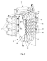
- the box (1) is arranged on the supporting structure (9), in which the capsule transporter (6) is also mounted which runs on rollers (10, 11, and 12).
- a device (13) for inserting capsules into the cell of the capsule transporter is also mounted, which is arranged between the outlet port (4) of the box (1) and the capsule transporter (6).
- the device (13) for inserting capsules is shown which is arranged between the outlet (4) of the box (1), Figure 2 , and the capsule transporter (6), mounted on the rollers (10, 11 and 12).
- the force exerted by the unloaded capsules entering the box (1) through the port (3) at the beginning of the circuit forces the loaded capsules (8) to exit the box through the outlet port (4) and avoids the rollback of the interior capsules.
- the circuit has a very specific geometry in order to avoid the cylinders being located in a staggered formation which would automatically cause a clogging and the interruption of the supply.
- a fixed idle capsule is located at the end of the circuit of loaded capsules and slides in the same manner as the capsules used but is fastened to a groove. Monitoring its position, the device effects the change of box as necessary.
- the capsule transporter (6) may consist of one, two or more transporter belts (15), four in the example in Figure 3 which are mounted in a parallel and coplanar position on a series of rollers, for example (3), Figures 2 and 3 , a drive roller (12) connected to an external drive, a tensor roller (11) which is displaced and allows the dismounting of the belt and absorbs the backlashes of the mounting of the belt and on a drive roller (10) which moves the capsule insertion device (13).
- the tensor roller (11) is displaceable and its fixing system absorbs elongations since its shaft is inserted into an inclined groove (16) and supported on an elastic element, since in this manner overloads are not transmitted.
- the angle of this groove (16) has an orientation such that the loads, which the normal functioning of the system can induce, are always perpendicular to the latter and do not cause a displacement in the direction of the groove.
- the transporter belt or belts (15) carry battlements (17), arranged in transverse alignments (18) between which the cells (19), which receive the capsules (8), are delimited.
- the battlements (17), positioned along the width of the belt or belts (15) are positioned in a heterogeneous manner in order to guarantee that the capsules (8) have multiple fastening points and are not displaced and also as a function of the fixing point of each battlement to its belt, the clamp effect of the consecutive battlements is going to be controllable by the geometry on which the belt or belts are displaced. Using this configuration of various belts, the mounting and the maintenance work is also facilitated.
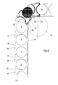
- the device (13) from Figure 3 can be observed in detail, which serves as a way of insertion for the capsules (8) from the outlet (4) of the box (1) to one of the cells (19), delimited between consecutive rows (18) of battlements (17).
- This device consists of a tilting shovel (22) with a curved profile that is arranged between the outlet port (4) of the box (1) and the transporter (6).
- the shovel (22) is mounted on a shaft (23) which is perpendicular to the direction of displacement of the transporter (6) and is actuated from the roller (10), Figure 2 , of the transporter belts, by means of a transmission system that includes gears (24) and an assembly of levers (25) which delimit an articulated quadrilateral.
- the tilting of the shovel (22) takes place between a capsule (8) receiving position (22a), Figure 6a , in which the concave side of the shovel is directed towards the outlet port (4) of the box (1) and a discharge position (22b), Figure 6b , in which the concavity of the shovel is directed towards a cell (19) facing the transporter (6) in order to discharge the capsule (8) in said cell and the convexity of the shovel directed towards the outlet port (4) of the box (1) in order to prevent the exit of capsules from said box.
- the shovel (22) moves the capsules to the cells between the battlements (17), the geometry of the shovel being conceived so as to support the capsule on all the axes while not supporting the configuration of the battlements.
- a fuel extraction chamber (5) is shown in a perspective view and diametric section, Figure 1 .
- This chamber has a transversal section approximately equal to that of the capsules (8) but not as long, and is closed by one of their bases (26) and open by the opposing base, this open base remaining close to the transporter belt or belts (15).
- the closed base (26) has a fuel outlet hole (27).
- the chamber (5) In a position adjacent to the open base, the chamber (5) has an inflatable peripheral seal (28) in its interior, while on the closed base, around the outlet hole (27) and also in the interior, it has a fuel-tight seal (28).
- the chamber (5) consists of two walls, one internal (30) and another external (31), between which is arranged a heating element (32) which can be actuated by induction, in which case the internal wall (30) is thermally insulated, or by the Joule effect, in which case said internal wall is thermally conductive. Furthermore, the internal wall (30) is fuel-tight.
- the external wall (31) is in turn mechanically resistant.
- the pusher-extractor device (14) is also shown, which consists of a linear actuator (33), for example at the base of a pneumatic cylinder, which is arranged in alignment with the chamber (5) and is located at the side opposing said chamber with respect to the belt or belts (15) of the transporter (6), close to said transporter.
- the linear actuator (33) carries, at the end directed towards the chamber (5), a clamp (34), Figure 8 , the closing and opening of which is caused by the effect of the pushing which the clamp effects on the capsule (8), upon introducing the capsule into the chamber (5) and on fixed stops (35), Figure 7 , located at the end of the extraction route.
- the actuator (14) pushes said capsule up to the chamber and, once emptied, pulls it until it is relocated in the same cell (19).
- the clamps (34) are characterized in that they are axially displaced by their actuator (14) and upon entering into contact with a capsule (8) they automatically hook the capsule. They insert it into the fuel release chamber (5) and maintain it fastened and under pressure while the fuel is released at almost atmospheric pressure. Latter, the clamp (34) pulls it again towards the transporter (6) and automatically releases it when it encounters the stop (35) which actuates the release mechanism installed for this purpose.
- the inflatable seal (28) may be controlled by the same pneumatic equipment as its linear actuator (14) and the same order, which causes the actuator to insert the capsule in the chamber, deflates the seal in order to, once again, minimize the controls of the system and the wear of the components. The same occurs conversely, the seal inflating when the actuator is stopped at its maximum elongation.
- the capsule is introduced in the chamber maintaining a controlled pressure of the actuator in order to prevent its travel back when the fuel is released at a pressure greater than atmospheric pressure.
- the capsule remains under pressure on the fuel-tight seal (29) and at this time the inflatable seal is inflated in order to guarantee that the method is fuel-tight.
- the capsule is then heated and the fuel is released which is extracted through the outlet hole (27).
- the actuator (14) maintains the pressure on the capsule and does not release it until, when it is emptied, the actuator is retracted and reaches a stop (35) on its linear displacement.
- the capsule returns to be collected by the cell (19) of the transporter which introduces it through the port (3) of the box (1), for example by means of a series of non-return ramps or combs which do not allow the capsules used to return backwards.
- the geometry of the capsule insertion device (13) is in particular conceived to avoid more than one capsule exiting the box and so that the capsule being moved is also unable to be displaced, considering possible accelerations in the different shafts.
- the equivalent mechanism does not have a special design which fulfils the functions previously mentioned.
- the transporter belt is formed by the very fastening pieces of the capsules, which are also not the type of clamp as described in the present invention.
- box (1) may be replaced by any system for feeding capsules to the transporter.
Landscapes
- Life Sciences & Earth Sciences (AREA)
- Engineering & Computer Science (AREA)
- Manufacturing & Machinery (AREA)
- Sustainable Development (AREA)
- Sustainable Energy (AREA)
- Chemical & Material Sciences (AREA)
- Chemical Kinetics & Catalysis (AREA)
- Electrochemistry (AREA)
- General Chemical & Material Sciences (AREA)
- Fuel Cell (AREA)
Priority Applications (1)
| Application Number | Priority Date | Filing Date | Title |
|---|---|---|---|
| EP15382098.0A EP3065210A1 (fr) | 2015-03-05 | 2015-03-05 | Mécanisme permettant de manipuler des capsules contenant un combustible pour des piles à combustible |
Applications Claiming Priority (1)
| Application Number | Priority Date | Filing Date | Title |
|---|---|---|---|
| EP15382098.0A EP3065210A1 (fr) | 2015-03-05 | 2015-03-05 | Mécanisme permettant de manipuler des capsules contenant un combustible pour des piles à combustible |
Publications (1)
| Publication Number | Publication Date |
|---|---|
| EP3065210A1 true EP3065210A1 (fr) | 2016-09-07 |
Family
ID=53016574
Family Applications (1)
| Application Number | Title | Priority Date | Filing Date |
|---|---|---|---|
| EP15382098.0A Withdrawn EP3065210A1 (fr) | 2015-03-05 | 2015-03-05 | Mécanisme permettant de manipuler des capsules contenant un combustible pour des piles à combustible |
Country Status (1)
| Country | Link |
|---|---|
| EP (1) | EP3065210A1 (fr) |
Citations (5)
| Publication number | Priority date | Publication date | Assignee | Title |
|---|---|---|---|---|
| EP0493918B1 (fr) | 1990-12-24 | 1996-11-27 | General Electric Company | Magasin et convoyeur |
| US7017569B2 (en) | 2001-07-11 | 2006-03-28 | Paul Garfield Jong | Paintball marker loader apparatus |
| WO2007143118A2 (fr) * | 2006-06-01 | 2007-12-13 | H2Volt, Inc. | Chargeur pour cellule À combustible |
| US20080032167A1 (en) * | 2006-08-07 | 2008-02-07 | Kabushiki Kaisha Toshiba | Fuel cartridge for fuel cell and fuel cell |
| US7979974B2 (en) | 2006-12-11 | 2011-07-19 | Hyundai Motor Company | System and method for successively feeding membrane electrode assemblies and separate plates of fuel cell stack |
-
2015
- 2015-03-05 EP EP15382098.0A patent/EP3065210A1/fr not_active Withdrawn
Patent Citations (5)
| Publication number | Priority date | Publication date | Assignee | Title |
|---|---|---|---|---|
| EP0493918B1 (fr) | 1990-12-24 | 1996-11-27 | General Electric Company | Magasin et convoyeur |
| US7017569B2 (en) | 2001-07-11 | 2006-03-28 | Paul Garfield Jong | Paintball marker loader apparatus |
| WO2007143118A2 (fr) * | 2006-06-01 | 2007-12-13 | H2Volt, Inc. | Chargeur pour cellule À combustible |
| US20080032167A1 (en) * | 2006-08-07 | 2008-02-07 | Kabushiki Kaisha Toshiba | Fuel cartridge for fuel cell and fuel cell |
| US7979974B2 (en) | 2006-12-11 | 2011-07-19 | Hyundai Motor Company | System and method for successively feeding membrane electrode assemblies and separate plates of fuel cell stack |
Similar Documents
| Publication | Publication Date | Title |
|---|---|---|
| FR2975375A1 (fr) | Systeme autonome de generation de puissance electrique et de conditionnement pour un aeronef, aeronef et procede associes | |
| EP3065210A1 (fr) | Mécanisme permettant de manipuler des capsules contenant un combustible pour des piles à combustible | |
| CN103537608B (zh) | 多种类铆钉自动输送装置 | |
| US4506588A (en) | Ammunition handling system and method | |
| CN109969441A (zh) | 雷管自动装盒机 | |
| KR101837590B1 (ko) | 실탄 수납장치 | |
| US6796530B2 (en) | Method and apparatus for providing pneumatic energy to an ejector | |
| GB1601481A (en) | Systems for handling articles eg ammunition | |
| US8459199B2 (en) | External storage device for deploying weapons from a submarine | |
| KR20170037942A (ko) | 잠수함용의 무기류 운반 시스템 | |
| US20080047417A1 (en) | Device for Feeding Propellant Charges to a Heavy Weapon | |
| US2386894A (en) | Method of and means for loading ammunition containers | |
| CN105722632A (zh) | 具有相对于平面基本成镜像布置的两个站的用于馈送电极胶囊的装置 | |
| US2494728A (en) | Ammunition feeder | |
| CN109484835A (zh) | 卸料机构 | |
| US11674766B2 (en) | Ammunition storage and feeding system | |
| CN105492856A (zh) | 炮装填时保持弹药的抓取装置 | |
| CN103009677B (zh) | 纸箱隔板自动插接机的刀板螺旋分料机构 | |
| KR102401759B1 (ko) | 자동차의 쉘을 위한 페인트 분배 설비 | |
| US2321142A (en) | Magazine for automatic guns | |
| GB2316157A (en) | Device for feeding ammunition into an airborne weapon | |
| WO2008074993A2 (fr) | Système de distribution de charge utile | |
| EP4574675A1 (fr) | Aéronef avec réservoirs de carburant | |
| US11377225B2 (en) | Fuel supply system for aerial vehicle | |
| CN117326190B (zh) | 气罐储存运输装置 |
Legal Events
| Date | Code | Title | Description |
|---|---|---|---|
| PUAI | Public reference made under article 153(3) epc to a published international application that has entered the european phase |
Free format text: ORIGINAL CODE: 0009012 |
|
| AK | Designated contracting states |
Kind code of ref document: A1 Designated state(s): AL AT BE BG CH CY CZ DE DK EE ES FI FR GB GR HR HU IE IS IT LI LT LU LV MC MK MT NL NO PL PT RO RS SE SI SK SM TR |
|
| AX | Request for extension of the european patent |
Extension state: BA ME |
|
| STAA | Information on the status of an ep patent application or granted ep patent |
Free format text: STATUS: THE APPLICATION IS DEEMED TO BE WITHDRAWN |
|
| 18D | Application deemed to be withdrawn |
Effective date: 20170308 |