EP3065262B1 - Dispositif de charge de terminal mobile et véhicule le comportant - Google Patents
Dispositif de charge de terminal mobile et véhicule le comportant Download PDFInfo
- Publication number
- EP3065262B1 EP3065262B1 EP14857192.0A EP14857192A EP3065262B1 EP 3065262 B1 EP3065262 B1 EP 3065262B1 EP 14857192 A EP14857192 A EP 14857192A EP 3065262 B1 EP3065262 B1 EP 3065262B1
- Authority
- EP
- European Patent Office
- Prior art keywords
- coil
- mobile
- charging
- foreign object
- charging coil
- Prior art date
- Legal status (The legal status is an assumption and is not a legal conclusion. Google has not performed a legal analysis and makes no representation as to the accuracy of the status listed.)
- Active
Links
Images


Classifications
-
- H—ELECTRICITY
- H02—GENERATION; CONVERSION OR DISTRIBUTION OF ELECTRIC POWER
- H02J—ELECTRIC POWER NETWORKS; CIRCUIT ARRANGEMENTS OR SYSTEMS FOR SUPPLYING OR DISTRIBUTING ELECTRIC POWER; SYSTEMS FOR STORING ELECTRIC ENERGY
- H02J50/00—Circuit arrangements or systems for wireless supply or distribution of electric power
- H02J50/90—Circuit arrangements or systems for wireless supply or distribution of electric power involving detection or optimisation of position, e.g. alignment
-
- H—ELECTRICITY
- H02—GENERATION; CONVERSION OR DISTRIBUTION OF ELECTRIC POWER
- H02J—ELECTRIC POWER NETWORKS; CIRCUIT ARRANGEMENTS OR SYSTEMS FOR SUPPLYING OR DISTRIBUTING ELECTRIC POWER; SYSTEMS FOR STORING ELECTRIC ENERGY
- H02J50/00—Circuit arrangements or systems for wireless supply or distribution of electric power
- H02J50/005—Mechanical details of housing or structure aiming to accommodate the power transfer means, e.g. mechanical integration of coils, antennas or transducers into emitting or receiving devices
-
- H—ELECTRICITY
- H02—GENERATION; CONVERSION OR DISTRIBUTION OF ELECTRIC POWER
- H02J—ELECTRIC POWER NETWORKS; CIRCUIT ARRANGEMENTS OR SYSTEMS FOR SUPPLYING OR DISTRIBUTING ELECTRIC POWER; SYSTEMS FOR STORING ELECTRIC ENERGY
- H02J50/00—Circuit arrangements or systems for wireless supply or distribution of electric power
- H02J50/10—Circuit arrangements or systems for wireless supply or distribution of electric power using inductive coupling
- H02J50/12—Circuit arrangements or systems for wireless supply or distribution of electric power using inductive coupling of the resonant type
-
- H—ELECTRICITY
- H02—GENERATION; CONVERSION OR DISTRIBUTION OF ELECTRIC POWER
- H02J—ELECTRIC POWER NETWORKS; CIRCUIT ARRANGEMENTS OR SYSTEMS FOR SUPPLYING OR DISTRIBUTING ELECTRIC POWER; SYSTEMS FOR STORING ELECTRIC ENERGY
- H02J50/00—Circuit arrangements or systems for wireless supply or distribution of electric power
- H02J50/60—Circuit arrangements or systems for wireless supply or distribution of electric power responsive to the presence of foreign objects, e.g. detection of living beings
-
- H—ELECTRICITY
- H02—GENERATION; CONVERSION OR DISTRIBUTION OF ELECTRIC POWER
- H02J—ELECTRIC POWER NETWORKS; CIRCUIT ARRANGEMENTS OR SYSTEMS FOR SUPPLYING OR DISTRIBUTING ELECTRIC POWER; SYSTEMS FOR STORING ELECTRIC ENERGY
- H02J7/00—Circuit arrangements for charging or discharging batteries or for supplying loads from batteries
- H02J7/70—Circuit arrangements for charging or discharging batteries or for supplying loads from batteries characterised by the mechanical construction
- H02J7/731—Circuit arrangements for charging or discharging batteries or for supplying loads from batteries characterised by the mechanical construction specially adapted for holding portable devices containing batteries
Definitions
- the present invention relates to a mobile-terminal charging device used to charge a mobile terminal such as a mobile phone, and a vehicle provided with the same.
- a mobile terminal such as a mobile phone
- power consumption thereof has also been increased. Therefore, charging the mobile terminal is required to be performed at any location including the inside of a vehicle, but, as a trend in recent years, a mobile-terminal charging device which can perform so-called noncontact charging has been attracting attention.
- the mobile-terminal charging device includes a support plate whose surface side serves as a mobile terminal placement portion, and a charging coil provided to oppose the rear surface side of the support plate. If a mobile terminal is placed on the mobile terminal placement portion, the mobile terminal can be charged by using magnetic fluxes from the charging coil (for example, the following PTLs 1 and 2 disclose techniques similar thereto).
- US 2009/153098 which is considered to represent the closest prior art discloses a wireless charging system with a movable charging coil. A plurality of position detection coils are used to determine the position of the element to be charged. The echo signal from the position detection coils is used to detect foreign matter.
- the present invention provides a mobile-terminal charging device which is convenient to use.
- a mobile-terminal charging device including a support plate whose front surface side is used as a mobile terminal placement portion; a charging coil; a driver; a controller; a memory connected to the controller; and a plurality of foreign object detection coils.
- the charging coil is movably disposed in a state of opposing the support plate on the rear surface side of the support plate.
- the driver can move the charging coil on the rear surface side of the support plate.
- the controller is connected to the charging coil and the driver.
- the plurality of foreign object detection coils are provided on the support plate and are connected to the controller.
- the memory stores a reference resonance frequency or a reference resonance voltage of each foreign object detection coil for each location where the charging coil is present.
- the controller performs a safety operation before conduction of the charging coil in a case where a resonance frequency detected by one of the plurality of foreign object detection coils corresponding to a location where the charging coil is present is higher than the reference resonance frequency stored in the memory, or a resonance voltage detected by one of the plurality of foreign object detection coils corresponding to a location where the charging coil is present is lower than the reference resonance voltage stored in the memory.
- the foreign object detection means is constituted of a metal detection antenna coil and an oscillation circuit connected thereto, and thus is not preferable in terms of versatility.
- the oscillation circuit is extremely delicately set, and thus the configuration is useful for charging a mobile terminal whose characteristics are known in advance.
- an oscillation state is changed by the mobile terminal, and, as a result, there is a mobile terminal which cannot be charged, and thus the configuration is not preferable in terms of versatility.
- the mobile-terminal charging device is provided in a vehicle interior of a vehicle, an unspecified large number of people frequently try to charge various types of mobile terminals. In this state, mobile terminals cannot be charged depending on models of the mobile terminals, and thus the mobile-terminal charging device is inconvenient.
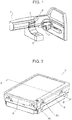
- steering wheel 3 is provided on the front side in vehicle interior 2 of vehicle 1.
- Electronic apparatus 4 which reproduces music or videos and displays car navigation images and the like is provided on the lateral side of steering wheel 3.
- Mobile-terminal charging device 5 is provided on the rear side of electronic apparatus 4 in vehicle interior 2.
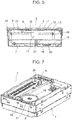
- Mobile-terminal charging device 5 includes, as illustrated in FIGS. 2 to 8 , box-shaped main body case 7 in which support plate 6 is disposed on an upper surface thereof, and charging coil 8 provided to be moved in a horizontal direction in a state of opposing a lower surface side of support plate 6 in main body case 7.
- the mobile-terminal charging device also includes driver 9 which causes charging coil 8 to be moved in the horizontal direction so as to oppose the lower surface side of support plate 6, and a controller (the reference numeral 10 in FIG. 9 ) connected to driver 9 and charging coil 8.
- support plate 6 will be described.
- support plate 6 has a configuration in which front surface plate 11, intermediate plate 12, and rear surface plate 13 overlap each other.
- Front surface plate 11 and rear surface plate 13 are made of synthetic resin, and intermediate plate 12 is made of ceramics. In other words, a magnetic flux from charging coil 8 can pass through support plate 6 toward mobile terminal 15.
- Position detection coil 14 illustrated in FIGS. 10 and 11 is provided in the Y direction and the X direction on front and rear surfaces of intermediate plate 12.
- Position detection coil 14 used in PTL 2 detects at which position mobile terminal 15 is placed on the mobile terminal placement portion which is the upper surface of support plate 6 as illustrated in FIG. 3 .
- position detection coil 14 detects at which position mobile terminal 15 is placed on the upper surface of support plate 6 as illustrated in FIG. 3 .
- driver 9 moves charging coil 8 to a position opposing a terminal charging coil (the reference numeral 15a in FIG. 14 ) of mobile terminal 15.
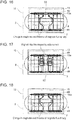
- Four foreign object detection coils 55 are disposed in a state of being close to each other in the Y direction on a front surface side (upper surface side) of front surface plate 11.
- Four foreign object detection coils 55 are disposed in a state of being close to each other in the Y direction on a rear surface side (lower surface side) of rear surface plate 13.
- foreign object detection coils 55 detect whether or not there is a foreign object on the front surface (upper surface side) of front surface plate 11 during non-conduction of charging coil 8. This will be described in detail in the following description of an operation thereof.
- charging coil 8 As illustrated in FIGS. 4 and 5 , charging coil 8 has a ring shape formed by winding a wiring material in a spiral shape. An outer peripheral side and a lower surface side of charging coil 8 are held by holding member 16 made of synthetic resin.
- Support leg 17 extending toward a lower side of charging coil 8 is integrally formed with holding member 16 on its lower surface by using synthetic resin as illustrated in FIG. 6 .
- a gap of 0.3 millimeters is provided between a lower surface of support leg 17 and an upper surface of metallic support plate 18 disposed under support leg 17. Therefore, in a normal state, the lower surface of support leg 17 is not in contact with the upper surface of support plate 18 during movement of charging coil 8.
- Control board 19 and a lower plate 20 of main body case 7 are disposed under support plate 18.
- Support member 21 penetrating through control board 19 is provided between a lower surface of support plate 18 and an upper surface of lower plate 20.
- the lower surface side of support plate 18 is supported by lower plate 20 of main body case 7 via support member 21 in order to increase the strength relative to excessive weight.
- driver 9 will be described.
- driver 9 includes X-axis direction driving shaft 22 and Y-axis direction driving shaft 23.
- An intermediate portion of each of X-axis direction driving shaft 22 and Y-axis direction driving shaft 23 is in contact with portions other than a portion of holding member 16 holding the charging coil.
- a penetration hole (not illustrated) through which X-axis direction driving shaft 22 penetrates and penetration hole 24 through which Y-axis direction driving shaft 23 penetrates are provided in holding member 16 with a predetermined gap in the vertical direction in a state of crossing each other.
- X-axis direction driving shaft 22 and Y-axis direction driving shaft 23 are in contact with each other at penetration hole 24.
- Worm wheel 25 is provided at one end side of X-axis direction driving shaft 22, gear 26 is provided at one end side thereof, and gear 26 is also provided at the other end side thereof. Worm wheel 25 is engaged with worm 27, and worm 27 is connected to motor 28. Gears 26 on both sides are respectively engaged with gear plates 29.
- Worm wheel 30 is provided at one end side of Y-axis direction driving shaft 23, gear 31 is provided at one end side thereof, and gear 31 is also provided at the other end side thereof. Worm wheel 30 is engaged with worm 32, and worm 32 is connected to motor 33. Gears 31 on both sides are respectively engaged with gear plates 34.
- Flexible wiring 35 illustrated in FIG. 4 causes a current to flow through charging coil 8. An end of flexible wiring 35 is fixed to the side surface of above-described support leg 17.
- controller 10 is connected to motor 28 via X-axis motor controller 36, and is connected to motor 33 via Y-axis motor controller 37.
- controller 10 can detect a position of charging coil 8. This will be described later.
- Controller 10 is connected to charging coil 8 via charging coil controller 38, and is also connected to position detection coil 14 via position detection coil controller 39.
- foreign object detection coil 55 detects whether or not there is a foreign object on the front surface side (upper surface side) of front surface plate 11 during non-conduction of charging coil 8.
- the presence of a foreign object is detected by large diameter detection coil 43 illustrated in FIGS. 12 and 13 provided between charging coil 8 and the mobile terminal placement portion of support plate 6, and detection coil 44 which is disposed inside detection coil 43 and has a smaller diameter than that of detection coil 43.
- charging coil 8 is movable depending on a location where mobile terminal 15 is placed. Therefore, the detection coils 43 and 44 are disposed on the upper surface of charging coil 8 (the lower surface of support plate 6) and are movable along with charging coil 8.
- Large diameter detection coil 43 has nearly the same size as the outer diameter of annular charging coil 8 (the detection coil is slightly smaller than the outer diameter of charging coil 8), and small diameter detection coil 44 has nearly the same size as the inner diameter of annular charging coil 8 (the detection coil is slightly larger than the inner diameter of charging coil 8).
- large diameter detection coil 43 and small diameter detection coil 44 are connected to controller 10 via voltage detectors 45 and 46, respectively.
- Memory 47 illustrated in FIG. 9 stores a program or the like for performing a safety operation on metal foreign objects by using large diameter detection coil 43 and small diameter detection coil 44.
- FIG. 14 illustrates a state in which mobile terminal 15 is being charged in a state in which there is no metal foreign object between the mobile terminal placement portion (the upper surface of support plate 6) and mobile terminal 15.
- magnetic body 48 is provided on a lower side (an opposite side to mobile terminal 15) of charging coil 8 and forms a magnetic path.
- Magnetic body 49 is provided on an upper side (an opposite side to mobile-terminal charging device 5) of terminal charging coil 15a and forms a magnetic path.
- a magnetic flux from charging coil 8 of mobile-terminal charging device 5 is supplied to terminal charging coil 15a of mobile terminal 15. This magnetic flux induces a voltage in terminal charging coil 15a, and thus mobile terminal 15 is charged.
- the magnetic flux having passed through terminal charging coil 15a returns to charging coil 8 via magnetic body 49, a space, and magnetic body 48 as indicated by arrows.
- FIG. 15 illustrates a state in which mobile terminal 15 is being charged in a state in which non-magnetic metal foreign object 50 (for example, a coin made of aluminum) is present between the mobile terminal placement portion (the upper surface of support plate 6) and mobile terminal 15.
- non-magnetic metal foreign object 50 for example, a coin made of aluminum
- the magnetic flux induced by the eddy current has a direction opposite to a direction of a magnetic flux directed from charging coil 8 toward terminal charging coil 15a in an inner portion of metal foreign object (the central direction of charging coil 8).
- the magnetic flux induced by the eddy current has the same direction as the direction of the magnetic flux directed from charging coil 8 toward terminal charging coil 15a in outer portions (a direction opposite to the center of charging coil 8).
- a magnetic flux advancing in the direction through the inner side of charging coil 8 is curved outward from the inner side portion of charging coil 8 and is then directed toward terminal charging coil 15a.
- the magnetic flux in the inner side portion of charging coil 8 decreases, and, conversely, the magnetic flux in the outer side portion of charging coil 8 increases.
- the distribution state of the magnetic fluxes illustrated in FIG. 16 can be detected by detection coils 43 and 44.
- a first voltage (V1) detected by large diameter detection coil 43 increases (as a result of there being a large number of magnetic fluxes, and a distance to the magnetic fluxes also becoming short)
- a second voltage (V2) detected by small diameter detection coil 44 decreases (as a result of there being a small number of magnetic fluxes, and a distance to the magnetic fluxes also becoming long).
- a peak voltage of the first voltage (V1) detected by large diameter detection coil 43 is detected by voltage detector 45
- a peak voltage of the second voltage (V2) detected by small diameter detection coil 44 is detected by voltage detector 46.
- Controller 10 compares the ratio (V2/V1) of the second voltage (V2) to the first voltage (V1) with a set value (which is stored in memory 47 and is, for example, 0.7), and performs a safety operation on the basis of a comparison result.
- the second voltage (V2) detected by small diameter detection coil 44 is, for example, 25% smaller than in the state (the absence of metal foreign object 50) illustrated in FIG. 14 .
- the first voltage (V1) detected by large diameter detection coil 43 is, for example, 170% larger than in the state (the absence of metal foreign object 50) illustrated in FIG. 14 .
- the ratio (V2/V1) of the second voltage (V2) to the first voltage (V1) is reduced by half or less (0.5 or less) in the state (the presence of metal foreign object 50) illustrated in FIG. 16 compared with the state (the absence of metal foreign object 50) illustrated in FIG. 14 .
- controller 10 Since the detected value (0.5 or less) is sufficiently smaller than the set value (0.7) stored in memory 47, controller 10 detects the presence of metal foreign object 50 so as to instantly stop the supply of a current to charging coil 8, and operates alarm 51 illustrated in FIGS. 2 and 9 .
- alarm 51 is connected to controller 10 as illustrated in FIG. 9 , and performs a notification of an abnormal state with a light when metal foreign object 50 is present.
- FIG. 17 illustrates a state in which mobile terminal 15 is being charged in a state in which magnetic metal foreign object 52 (for example, an iron substance) is present between the mobile terminal placement portion (the upper surface of support plate 6) and mobile terminal 15.
- magnetic metal foreign object 52 for example, an iron substance
- This metal foreign object 52 is a magnetic body, and magnetic fluxes advancing into metal foreign object 52 include magnetic fluxes passing therethrough and magnetic fluxes advancing thereinto, for example, outward. Therefore, FIG. 17 illustrates the additional magnetic flux caused by the eddy current unlike FIG. 15 .
- the magnetic flux which is additionally generated in this way has a direction opposite to the direction of the magnetic flux directed from charging coil 8 toward terminal charging coil 15a in an inner portion thereof (the central direction of charging coil 8).
- the magnetic flux has the same direction as the direction of the magnetic flux directed from charging coil 8 toward terminal charging coil 15a in an outer portion (a direction opposite to the center of charging coil 8) of the magnetic flux induced by the eddy current.
- a magnetic flux advancing in the direction through the inner side of charging coil 8 is curved outward from the inner side portion of charging coil 8 and is then directed toward terminal charging coil 15a (some magnetic fluxes advance into metal foreign object 52 in the outer side thereof).
- the first voltage (V1) detected by large diameter detection coil 43 increases (as a result of there being a large number of magnetic fluxes, and a distance to the magnetic fluxes also becoming short), and, conversely, the second voltage (V2) detected by small diameter detection coil 44 decreases (as a result of there being a small number of magnetic fluxes, and a distance to the magnetic fluxes also becoming long).
- Controller 10 compares the ratio (V2/V1) of the second voltage (V2) to the first voltage (V1) with a set value (which is stored in memory 47 and is, for example, 0.7), and performs a safety operation on the basis of a comparison result.
- the second voltage (V2) detected by small diameter detection coil 44 is, for example, 15% smaller than in the state (the absence of metal foreign object 52) illustrated in FIG. 14 .
- the first voltage (V1) detected by large diameter detection coil 43 is, for example, 170% larger than in the state (the absence of metal foreign object 52) illustrated in FIG. 14 .
- the ratio (V2/V1) of the second voltage (V2) to the first voltage (V1) is reduced by half or less (0.5 or less) in the state (the presence of metal foreign object 52) illustrated in FIG. 17 compared with the state (the absence of metal foreign object 52) illustrated in FIG. 14 .
- controller 10 Since the detected value (0.5 or less) is sufficiently smaller than the set value (0.7) stored in memory 47, controller 10 detects the presence of metal foreign object 52 so as to instantly stop the supply of a current to charging coil 8, and operates alarm 51 illustrated in FIGS. 2 and 9 . In other words, controller 10 lights alarm 51 so as to perform a notification of an abnormal state.
- controller 10 can reliably detect the presence of metal foreign object 50 or 52, and can reliably perform a safety operation.
- An operation of detecting metal foreign object 50 or 52 is not substantially influenced by whether the metal foreign object is a magnetic body or a non-magnetic body, or the type of charged mobile terminal 15. Therefore, the mobile-terminal charging device can charge various mobile terminals 15 with versatility and is considerably convenient to use.
- a safety operation is performed on the basis of a comparison result of a voltage ratio (V2/V1) and a set value by using the first voltage (V1) detected by large diameter detection coil 43 and the second voltage (V2) detected by small diameter detection coil 44.
- V2/V1 voltage ratio
- V2 second voltage
- an exemplary embodiment of the present invention is not limited to such a configuration.
- a safety operation is performed on the basis of a comparison result of the ratio (V1/V2) of the first voltage to the second voltage and a set value.
- the safety operation is performed in a case where the voltage ratio (V1/V2) is more than the set value.
- mobile-terminal charging device 5 is provided in vehicle interior 2 of vehicle 1. This is because a coin or the like is frequently placed on support plate 6 in vehicle 1.
- mobile-terminal charging device 5 of the present exemplary embodiment in vehicle interior 2 of vehicle 1.
- intermediate diameter detection coil 54 switching between the detection coils 43, 44 and 54 for comparison can be performed, or situations between detection coils 43 and 54, and 54 and 44 can be detected.
- Detection coil 43 and detection coil 44 are not limited to circular shapes. In other words, as long as a magnetic flux change can be converted into a voltage, an elliptical coil, a rectangular coil whose corner portion is arced, or the like may be used as a detection coil.
- foreign object detection coils 55 detect whether or not there is a foreign object on the front surface side (upper surface side) of front surface plate 11 during non-conduction of charging coil 8. Next, an operation thereof will be described in detail.
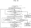
- step S1 in FIG. 19 if power switch 40 illustrated in FIGS. 2 and 9 is turned on (step S1 in FIG. 19 ), a position of charging coil 8 is initialized (step S2 in FIG. 19 ).
- the position initialization indicates that controller 10 drives motors 28 and 33 via X-axis motor controller 36 and Y-axis motor controller 37 so as to return charging coil 8 to the corner (coordinates xo and yo) illustrated in FIG. 7 .
- controller 10 determines that a position of charging coil 8 has been initialized.
- Controller 10 supplies detection pulses to the above-described eight foreign object detection coils 55, respectively.
- controller 10 performs a safety operation (steps S3 and S4 in FIG. 19 ).
- FIG. 20 illustrates a state in which a resonance frequency of corresponding foreign object detection coil 55 is influenced by a location where charging coil 8 is present.
- line A of FIG. 20 indicates resonance frequencies of respective foreign object detection coils 55 when charging coil 8 is present at coordinates (10,0), and indicates a situation in which resonance frequencies of foreign object detection coils 55 near charging coil 8 are lowered.
- Line B of FIG. 20 indicates resonance frequencies of respective foreign object detection coils 55 when charging coil 8 is present at coordinates (10,35), and indicates a situation in which resonance frequencies of foreign object detection coils 55 near charging coil 8 are lowered.
- Line A of FIG. 21 indicates resonance voltages of respective foreign object detection coils 55 when charging coil 8 is present at coordinates (10,0), and indicates a situation in which resonance voltages of foreign object detection coils 55 near charging coil 8 are heightened.
- Line B of FIG. 21 indicates resonance voltages of respective foreign object detection coils 55 when charging coil 8 is present at coordinates (10,35), and indicates a situation in which resonance voltages of foreign object detection coils 55 near charging coil 8 are heightened.
- Line A of FIG. 22 indicates resonance frequencies of respective foreign object detection coils 55 in a case where a metal foreign object is absent when charging coil 8 is present at coordinates (10,0).
- Line B of FIG. 22 indicates resonance frequencies of respective foreign object detection coils 55 in a case where a metal foreign object is present at fourth foreign object detection coil 55 when charging coil 8 is present at coordinates (10,0), and indicates a situation in which resonance frequencies of foreign object detection coils 55 near charging coil 8 are heightened.
- Line A of FIG. 23 indicates resonance voltages of respective foreign object detection coils 55 in a case where a metal foreign object is absent when charging coil 8 is present at coordinates (10,0).
- Line B of FIG. 23 indicates resonance voltages of respective foreign object detection coils 55 in a case where a metal foreign object is present at fourth foreign object detection coil 55 when charging coil 8 is present at coordinates (10,0), and indicates a situation in which resonance voltages of foreign object detection coils 55 near charging coil 8 are lowered.
- a metal foreign object is detected by foreign object detection coil 55 during non-conduction of charging coil 8 on the basis of such a phenomenon.
- memory 47 stores a reference resonance frequency and a reference resonance voltage of each foreign object detection coil 55 for each location where charging coil 8 is present.
- controller 10 detects that charging coil 8 has returned to the corner (coordinates xo and yo) illustrated in FIG. 7 by using switches 41 and 42. Consequently, controller 10 can detect a location where charging coil 8 is present.
- controller 10 identifies the presence of a foreign object. If the presence of the foreign object is identified, controller 10 causes alarm 51 to perform a safety operation (steps S3 and S4 in FIG. 19 ).
- the safety operation during non-conduction of charging coil 8 is performed by alarm 51, but, there may be a configuration in which, if the metal foreign object is not removed thereafter, conduction of charging coil 8 cannot be performed.
- position detection coil 14 detects a location where mobile terminal 15 is placed (step S5 in FIG. 19 ).
- driver 9 moves charging coil 8 to the location (step S6 in FIG. 19 ).
- controller 10 performs conduction of charging coil 8 (step S7 in FIG. 19 ), and a foreign object detection operation in large diameter detection coil 43 and small diameter detection coil 44 provided on the upper surface side of charging coil 8 (terminal charging coil 15a side) (step S8 in FIG. 19 ).
- controller 10 issues a warning with alarm 51 and stops charging using charging coil 8 as a safety operation (step S9 in FIG. 19 ).
- next mobile terminal 15 is subsequently placed on the upper surface of support plate 6 in a state in which charging is finished (step S10 in FIG. 19 ), herein, a position of charging coil 8 is stored in memory 47 (step S11 in FIG. 19 ), and charging is finished (step S12 in FIG. 19 ).
- step S11 in FIG. 19 the position of charging coil 8 is stored in memory 47 (step S11 in FIG. 19 ) and charging is finished (step S12 in FIG. 19 ).
- mobile-terminal charging device 5 includes support plate 18 whose front surface side is used as a mobile terminal placement portion; charging coil 8; driver 9; controller 10; memory 47 connected to controller 10; and a plurality of foreign object detection coils 55.
- Charging coil 8 is movably disposed in a state of opposing support plate 18 on a rear surface side of support plate 18.
- Driver 9 can move charging coil 8 on the rear surface side of support plate 18.
- Controller 10 is connected to charging coil 8 and driver 9.
- the plurality of foreign object detection coils 55 are provided on support plate 18 and are connected to controller 10.
- Memory 47 stores a reference resonance frequency or a reference resonance voltage of each foreign object detection coil 55 for each location where charging coil 8 is present.
- controller 10 Before conduction of charging coil 8 is performed, in a case where a resonance frequency detected by foreign object detection coil 55 corresponding to a location where charging coil 8 is present is higher than the reference resonance frequency stored in memory 47, or a resonance voltage detected by foreign object detection coil 55 corresponding to a location where charging coil 8 is present is lower than the reference resonance voltage stored in memory 47, controller 10 performs a safety operation. Therefore, convenience is improved.
- the mobile-terminal charging device is expected as an on-vehicle charging device or a household charging device.
Landscapes
- Engineering & Computer Science (AREA)
- Power Engineering (AREA)
- Computer Networks & Wireless Communication (AREA)
- Charge And Discharge Circuits For Batteries Or The Like (AREA)
Claims (13)
- Dispositif de charge (5) de terminal mobile comprenant :une plaque de support (6) dont la surface avant est utilisée comme organe de placement de terminal mobile,une bobine de charge (8) qui est placée tout en pouvant bouger de façon à s'opposer à la plaque de support (6),un dispositif de pilotage (9) qui peut déplacer la bobine de charge (8) sur le côté de surface arrière de la plaque de support (6),un contrôleur (10) qui est relié à la bobine de charge (8) et au dispositif de pilotage (9),une mémoire (47) qui est reliée au contrôleur (10), etune pluralité de bobines de détection d'objets étrangers (55) qui sont prévues sur la plaque de support (6) et qui sont reliées au contrôleur (10),caractérisé en ce quela mémoire (47) stocke une fréquence de résonance de référence ou une tension de résonance de référence pour chacune de la pluralité de bobines de détection d'objets étrangers (55) pour chaque emplacement où se trouve la bobine de charge (8), etle contrôleur (10) effectue une opération de sécurité pendant l'arrêt de conduction de la bobine de charge (8) dans le cas où une fréquence de résonance détectée par l'une de la pluralité de bobines de détection d'objets étrangers (55), correspondant à un emplacement ou se trouve la bobine de charge (8), est supérieure à la fréquence de résonance de référence stockée dans la mémoire (47), ou bien si une tension de résonance détectée par l'une de la pluralité de bobines de détection d'objets étrangers (55), correspondant à un emplacement ou se trouve la bobine de charge (8), est inférieure à la tension de résonance de référence stockée dans la mémoire (47).
- Dispositif de charge (5) de terminal mobile selon la revendication 1,
dans lequel une première bobine de détection (43) et une deuxième bobine de détection (44), qui est placée à l'intérieur de la première bobine de détection (43) et présente un diamètre plus petit que le diamètre de la première bobine de détection (43), sont utilisées dans la bobine de charge (8), la première bobine de détection (43) et la deuxième bobine de détection (44) étant reliées au contrôleur (10), et
dans lequel, dans un état où la bobine de charge (8) se trouve à l'état de conduction, le contrôleur (10) compare à une valeur de consigne un rapport, établi entre une première tension (V1), détectée par la première bobine de détection (43), et une seconde tension (V2), détectée par la deuxième bobine de détection (44), et il effectue l'opération de sécurité sur la base du résultat de la comparaison. - Dispositif de charge (5) de terminal mobile selon la revendication 2,
dans lequel la bobine de charge (8) présente une forme d'anneau formé en enroulant un matériau de câblage sous la forme d'une spirale, et la première bobine de détection (43) tout comme la deuxième bobine de détection (44) sont disposées sur une surface de la bobine de charge (8) opposée à la plaque de support (6). - Dispositif de charge (5) de terminal mobile selon la revendication 2,
dans lequel le diamètre externe de la première bobine de détection (43) est sensiblement identique au diamètre externe de la bobine de charge (8), et le diamètre externe de la deuxième bobine de détection (44) est sensiblement identique au diamètre interne de la bobine de charge (8). - Dispositif de charge (5) de terminal mobile selon la revendication 2,
dans lequel une troisième bobine de détection (54), placée entre les première et deuxième bobines de détection (43, 44), est en outre prévue dans la bobine de charge (8). - Dispositif de charge (5) de terminal mobile selon la revendication 2,
dans lequel le contrôleur (10) interdit la conduction de la bobine de charge (8) en tant qu'opération de sécurité, laquelle est effectuée comme résultat de comparaison obtenu en comparant à la valeur de consigne le rapport entre la première tension (V1) détectée par la première bobine de détection (43) et la seconde tension (V2) détectée par la deuxième bobine de détection (44). - Dispositif de charge (5) de terminal mobile selon la revendication 2,
une alarme (51) qui est reliée au contrôleur (10),
dans lequel le contrôleur (10) manoeuvre l'alarme (51) en tant qu'opération de sécurité, laquelle est effectuée comme résultat de comparaison obtenu en comparant à la valeur de consigne le rapport entre la première tension (V1) détectée par la première bobine de détection (43) et la seconde tension (V2) détectée par la deuxième bobine de détection (44). - Dispositif de charge (5) de terminal mobile selon la revendication 1,
dans lequel les différentes bobines de détection d'objets étrangers (55) sont prévues sur les surfaces avant et arrière de la plaque de support (6). - Dispositif de charge (5) de terminal mobile selon la revendication 1, comprenant en outre :une alarme (51) qui est reliée au contrôleur (10),dans lequel le contrôleur (10) amène l'alarme (51) à émettre une alerte lorsqu'est effectuée l'opération de sécurité avant la conduction de la bobine de charge (8).
- Dispositif de charge (5) de terminal mobile selon la revendication 1, comprenant en outre :un détecteur de tension (45, 46) qui est relié au contrôleur (10) et qui est également relié à la première bobine de détection (43) et à la deuxième bobine de détection (44) de sorte à mesurer une tension crête.
- Dispositif de charge (5) de terminal mobile selon la revendication 1,
dans lequel, après qu'est effectuée une charge utilisant la bobine de charge (8), le contrôleur (10) enregistre l'emplacement où se trouve la bobine de charge (8) dans la mémoire (47). - Véhicule (1) comprenant :un intérieur de véhicule (2), etle dispositif de charge (5) de terminal mobile conforme à l'une quelconque des revendications 1 à 11, placé dans l'intérieur du véhicule (2) de sorte à ce que l'organe de placement de terminal mobile fasse face vers le haut.
- Véhicule (1) selon la revendication 12, comprenant :un organe de garde (53) le long de la périphérie externe de la plaque de support (6), l'organe de garde (53) dépassant vers le haut hors de la plaque de support (6).
Applications Claiming Priority (4)
| Application Number | Priority Date | Filing Date | Title |
|---|---|---|---|
| JP2013227925 | 2013-11-01 | ||
| JP2013239492 | 2013-11-20 | ||
| JP2013245749 | 2013-11-28 | ||
| PCT/JP2014/005485 WO2015064103A1 (fr) | 2013-11-01 | 2014-10-30 | Dispositif de charge de terminal mobile et véhicule le comportant |
Publications (3)
| Publication Number | Publication Date |
|---|---|
| EP3065262A1 EP3065262A1 (fr) | 2016-09-07 |
| EP3065262A4 EP3065262A4 (fr) | 2016-11-23 |
| EP3065262B1 true EP3065262B1 (fr) | 2018-04-04 |
Family
ID=53003729
Family Applications (2)
| Application Number | Title | Priority Date | Filing Date |
|---|---|---|---|
| EP14857192.0A Active EP3065262B1 (fr) | 2013-11-01 | 2014-10-30 | Dispositif de charge de terminal mobile et véhicule le comportant |
| EP14857685.3A Active EP3065263B1 (fr) | 2013-11-01 | 2014-10-30 | Dispositif de charge de terminal mobile et véhicule équipé de celui-ci |
Family Applications After (1)
| Application Number | Title | Priority Date | Filing Date |
|---|---|---|---|
| EP14857685.3A Active EP3065263B1 (fr) | 2013-11-01 | 2014-10-30 | Dispositif de charge de terminal mobile et véhicule équipé de celui-ci |
Country Status (4)
| Country | Link |
|---|---|
| US (2) | US9985463B2 (fr) |
| EP (2) | EP3065262B1 (fr) |
| JP (2) | JP6467638B2 (fr) |
| WO (2) | WO2015064103A1 (fr) |
Families Citing this family (20)
| Publication number | Priority date | Publication date | Assignee | Title |
|---|---|---|---|---|
| EP3032687B1 (fr) * | 2013-07-18 | 2017-11-29 | Panasonic Intellectual Property Management Co., Ltd. | Chargeur sans contact, programme associé, et automobile équipée dudit chargeur sans contact |
| EP3121924B1 (fr) * | 2013-12-25 | 2019-04-03 | Panasonic Intellectual Property Management Co., Ltd. | Appareil de charge pour borne portable et véhicule automobile équipé de l'appareil de charge pour borne portable |
| US20170117740A1 (en) * | 2014-03-24 | 2017-04-27 | Panasonic Intellectual Property Management Co., Ltd. | Mobile terminal charging device and vehicle mounted with same |
| US20160380439A1 (en) * | 2015-06-26 | 2016-12-29 | Lei Shao | Notification techniques for wireless power transfer systems |
| FR3043275B1 (fr) * | 2015-10-28 | 2019-03-15 | Continental Automotive France | Procede de detection d'un objet metallique dans la zone d'emission d'un dispositif de recharge d'un equipement d'utilisateur pour vehicule automobile |
| US10212519B2 (en) | 2015-11-19 | 2019-02-19 | The Lovesac Company | Electronic furniture systems with integrated internal speakers |
| US12495253B2 (en) | 2015-11-19 | 2025-12-09 | The Lovesac Company | Systems and methods for tuning based on furniture configuration |
| US12507009B2 (en) | 2015-11-19 | 2025-12-23 | The Lovesac Company | Systems and methods for correcting sound loss through partially acoustically transparent materials |
| US11689856B2 (en) | 2015-11-19 | 2023-06-27 | The Lovesac Company | Electronic furniture systems with integrated induction charger |
| CN105356562B (zh) * | 2015-11-24 | 2017-09-15 | 东南大学 | 一种分段发射式电动汽车在线动态无线供电系统 |
| TWI606666B (zh) * | 2016-04-25 | 2017-11-21 | 無線電力傳輸裝置及其金屬異物偵測線圈的結構 | |
| US11129996B2 (en) * | 2016-06-15 | 2021-09-28 | Boston Scientific Neuromodulation Corporation | External charger for an implantable medical device for determining position and optimizing power transmission using resonant frequency as determined from at least one sense coil |
| EP3346581B1 (fr) * | 2017-01-04 | 2023-06-14 | LG Electronics Inc. | Chargeur sans fil destiné à un terminal mobile dans un véhicule |
| CN108855999A (zh) * | 2017-05-12 | 2018-11-23 | 中惠创智无线供电技术有限公司 | 一种无线充电系统发射线圈平面异物检测处理装置 |
| JP7307615B2 (ja) * | 2019-07-10 | 2023-07-12 | 株式会社Subaru | 電動車両 |
| JP7253996B2 (ja) * | 2019-07-29 | 2023-04-07 | 株式会社Subaru | 車載用の非接触充電装置及び車両 |
| JP7452173B2 (ja) | 2020-03-26 | 2024-03-19 | オムロン株式会社 | 異物検出装置 |
| US20220052565A1 (en) * | 2020-08-15 | 2022-02-17 | Aira, Inc. | Resonant Reflection Device Detection |
| FR3117220B1 (fr) * | 2020-12-03 | 2022-10-21 | Continental Automotive Gmbh | Procede de detection d’un objet metallique parasite sur une surface de charge et dispositif de charge associe |
| CN114204692B (zh) | 2021-05-17 | 2025-08-26 | 伏达半导体(合肥)股份有限公司 | 双接收器检测装置及用于无线电能传输系统的方法 |
Family Cites Families (20)
| Publication number | Priority date | Publication date | Assignee | Title |
|---|---|---|---|---|
| JPWO2009040998A1 (ja) * | 2007-09-27 | 2011-01-13 | パナソニック株式会社 | 非接触充電器 |
| JP5362330B2 (ja) | 2007-12-18 | 2013-12-11 | 三洋電機株式会社 | 充電台 |
| KR20100130215A (ko) * | 2008-03-17 | 2010-12-10 | 파우워매트 엘티디. | 유도송전장치 |
| US9407327B2 (en) * | 2009-02-13 | 2016-08-02 | Qualcomm Incorporated | Wireless power for chargeable and charging devices |
| JP5304885B2 (ja) * | 2009-03-17 | 2013-10-02 | 富士通株式会社 | 無線電力供給システム |
| JP5362453B2 (ja) * | 2009-06-16 | 2013-12-11 | 三洋電機株式会社 | 充電台 |
| DE112010002338T5 (de) * | 2009-06-25 | 2012-08-02 | Tanashin Denki Co., Ltd. | Zweidimensionale Verschiebeeinrichtung |
| WO2011090620A2 (fr) * | 2009-12-28 | 2011-07-28 | Toyoda Gosei Co. Ltd | Plateau pour la charge ou la connexion destiné à des dispositifs électroniques portatifs |
| EP2555379B1 (fr) * | 2010-03-31 | 2015-03-04 | Honda Motor Co., Ltd. | Système de charge sans contact |
| JP2012016125A (ja) | 2010-06-30 | 2012-01-19 | Panasonic Electric Works Co Ltd | 非接触給電システム及び非接触給電システムの金属異物検出装置 |
| JP5543881B2 (ja) * | 2010-09-16 | 2014-07-09 | 株式会社東芝 | 無線電力伝送装置 |
| US9294153B2 (en) * | 2010-09-23 | 2016-03-22 | Texas Instruments Incorporated | Systems and methods of wireless power transfer with interference detection |
| JP5426510B2 (ja) * | 2010-09-27 | 2014-02-26 | 株式会社東芝 | 無線電力伝送装置 |
| US9178369B2 (en) * | 2011-01-18 | 2015-11-03 | Mojo Mobility, Inc. | Systems and methods for providing positioning freedom, and support of different voltages, protocols, and power levels in a wireless power system |
| JP2012244732A (ja) * | 2011-05-18 | 2012-12-10 | Sony Corp | 電磁結合状態検知回路、送電装置、非接触電力伝送システム及び電磁結合状態検知方法 |
| CN103222150A (zh) * | 2011-09-02 | 2013-07-24 | 松下电器产业株式会社 | 车载充电装置 |
| JP6002931B2 (ja) * | 2011-12-07 | 2016-10-05 | パナソニックIpマネジメント株式会社 | 車載用充電器 |
| JP5872373B2 (ja) * | 2012-04-25 | 2016-03-01 | 三洋電機株式会社 | 無接点給電方法 |
| US9178361B2 (en) * | 2012-09-27 | 2015-11-03 | ConvenientPower, Ltd. | Methods and systems for detecting foreign objects in a wireless charging system |
| JP2014225963A (ja) * | 2013-05-16 | 2014-12-04 | ソニー株式会社 | 検知装置、給電システム、および、検知装置の制御方法 |
-
2014
- 2014-10-30 US US15/026,990 patent/US9985463B2/en active Active
- 2014-10-30 EP EP14857192.0A patent/EP3065262B1/fr active Active
- 2014-10-30 JP JP2015544811A patent/JP6467638B2/ja active Active
- 2014-10-30 EP EP14857685.3A patent/EP3065263B1/fr active Active
- 2014-10-30 WO PCT/JP2014/005485 patent/WO2015064103A1/fr not_active Ceased
- 2014-10-30 WO PCT/JP2014/005484 patent/WO2015064102A1/fr not_active Ceased
- 2014-10-30 US US15/027,729 patent/US10355511B2/en active Active
- 2014-10-30 JP JP2015544812A patent/JP6467639B2/ja active Active
Non-Patent Citations (1)
| Title |
|---|
| None * |
Also Published As
| Publication number | Publication date |
|---|---|
| EP3065263A1 (fr) | 2016-09-07 |
| EP3065262A1 (fr) | 2016-09-07 |
| JP6467638B2 (ja) | 2019-02-13 |
| EP3065263A4 (fr) | 2016-09-07 |
| JPWO2015064102A1 (ja) | 2017-03-09 |
| EP3065262A4 (fr) | 2016-11-23 |
| JPWO2015064103A1 (ja) | 2017-03-09 |
| US10355511B2 (en) | 2019-07-16 |
| US20160261130A1 (en) | 2016-09-08 |
| WO2015064102A1 (fr) | 2015-05-07 |
| US20160241064A1 (en) | 2016-08-18 |
| EP3065263B1 (fr) | 2017-10-18 |
| US9985463B2 (en) | 2018-05-29 |
| WO2015064103A1 (fr) | 2015-05-07 |
| JP6467639B2 (ja) | 2019-02-13 |
Similar Documents
| Publication | Publication Date | Title |
|---|---|---|
| EP3065262B1 (fr) | Dispositif de charge de terminal mobile et véhicule le comportant | |
| EP3121924B1 (fr) | Appareil de charge pour borne portable et véhicule automobile équipé de l'appareil de charge pour borne portable | |
| EP3151365B1 (fr) | Dispositif de charge de terminal mobile et véhicule dans lequel celui-ci est monté | |
| EP3086436B1 (fr) | Dispositif de charge sans contact, programme associé et automobile comportant un dispositif de charge sans contact monté dans ladite automobile | |
| US20160164333A1 (en) | Contactless charger, program therefor, and automobile equipped with same | |
| EP3131179B1 (fr) | Dispositif de charge de terminal mobile et véhicule équipé de celui-ci | |
| EP3046208B1 (fr) | Dispositif de chargement de terminal portable et automobile équipée de celui-ci |
Legal Events
| Date | Code | Title | Description |
|---|---|---|---|
| PUAI | Public reference made under article 153(3) epc to a published international application that has entered the european phase |
Free format text: ORIGINAL CODE: 0009012 |
|
| 17P | Request for examination filed |
Effective date: 20160412 |
|
| AK | Designated contracting states |
Kind code of ref document: A1 Designated state(s): AL AT BE BG CH CY CZ DE DK EE ES FI FR GB GR HR HU IE IS IT LI LT LU LV MC MK MT NL NO PL PT RO RS SE SI SK SM TR |
|
| AX | Request for extension of the european patent |
Extension state: BA ME |
|
| A4 | Supplementary search report drawn up and despatched |
Effective date: 20161024 |
|
| RIC1 | Information provided on ipc code assigned before grant |
Ipc: H02J 50/00 20160101AFI20161018BHEP Ipc: H02J 50/60 20160101ALI20161018BHEP Ipc: H02J 50/12 20160101ALI20161018BHEP |
|
| DAX | Request for extension of the european patent (deleted) | ||
| RIC1 | Information provided on ipc code assigned before grant |
Ipc: H02J 50/00 20160101AFI20170411BHEP Ipc: H02J 50/12 20160101ALI20170411BHEP Ipc: H02J 50/60 20160101ALI20170411BHEP |
|
| GRAP | Despatch of communication of intention to grant a patent |
Free format text: ORIGINAL CODE: EPIDOSNIGR1 |
|
| INTG | Intention to grant announced |
Effective date: 20170519 |
|
| GRAJ | Information related to disapproval of communication of intention to grant by the applicant or resumption of examination proceedings by the epo deleted |
Free format text: ORIGINAL CODE: EPIDOSDIGR1 |
|
| INTC | Intention to grant announced (deleted) | ||
| GRAP | Despatch of communication of intention to grant a patent |
Free format text: ORIGINAL CODE: EPIDOSNIGR1 |
|
| INTG | Intention to grant announced |
Effective date: 20171013 |
|
| GRAS | Grant fee paid |
Free format text: ORIGINAL CODE: EPIDOSNIGR3 |
|
| GRAA | (expected) grant |
Free format text: ORIGINAL CODE: 0009210 |
|
| AK | Designated contracting states |
Kind code of ref document: B1 Designated state(s): AL AT BE BG CH CY CZ DE DK EE ES FI FR GB GR HR HU IE IS IT LI LT LU LV MC MK MT NL NO PL PT RO RS SE SI SK SM TR |
|
| REG | Reference to a national code |
Ref country code: GB Ref legal event code: FG4D |
|
| REG | Reference to a national code |
Ref country code: CH Ref legal event code: EP |
|
| REG | Reference to a national code |
Ref country code: AT Ref legal event code: REF Ref document number: 986596 Country of ref document: AT Kind code of ref document: T Effective date: 20180415 |
|
| REG | Reference to a national code |
Ref country code: IE Ref legal event code: FG4D |
|
| REG | Reference to a national code |
Ref country code: DE Ref legal event code: R096 Ref document number: 602014023523 Country of ref document: DE |
|
| REG | Reference to a national code |
Ref country code: NL Ref legal event code: MP Effective date: 20180404 |
|
| REG | Reference to a national code |
Ref country code: LT Ref legal event code: MG4D |
|
| PG25 | Lapsed in a contracting state [announced via postgrant information from national office to epo] |
Ref country code: NL Free format text: LAPSE BECAUSE OF FAILURE TO SUBMIT A TRANSLATION OF THE DESCRIPTION OR TO PAY THE FEE WITHIN THE PRESCRIBED TIME-LIMIT Effective date: 20180404 |
|
| PG25 | Lapsed in a contracting state [announced via postgrant information from national office to epo] |
Ref country code: LT Free format text: LAPSE BECAUSE OF FAILURE TO SUBMIT A TRANSLATION OF THE DESCRIPTION OR TO PAY THE FEE WITHIN THE PRESCRIBED TIME-LIMIT Effective date: 20180404 Ref country code: PL Free format text: LAPSE BECAUSE OF FAILURE TO SUBMIT A TRANSLATION OF THE DESCRIPTION OR TO PAY THE FEE WITHIN THE PRESCRIBED TIME-LIMIT Effective date: 20180404 Ref country code: ES Free format text: LAPSE BECAUSE OF FAILURE TO SUBMIT A TRANSLATION OF THE DESCRIPTION OR TO PAY THE FEE WITHIN THE PRESCRIBED TIME-LIMIT Effective date: 20180404 Ref country code: AL Free format text: LAPSE BECAUSE OF FAILURE TO SUBMIT A TRANSLATION OF THE DESCRIPTION OR TO PAY THE FEE WITHIN THE PRESCRIBED TIME-LIMIT Effective date: 20180404 Ref country code: FI Free format text: LAPSE BECAUSE OF FAILURE TO SUBMIT A TRANSLATION OF THE DESCRIPTION OR TO PAY THE FEE WITHIN THE PRESCRIBED TIME-LIMIT Effective date: 20180404 Ref country code: SE Free format text: LAPSE BECAUSE OF FAILURE TO SUBMIT A TRANSLATION OF THE DESCRIPTION OR TO PAY THE FEE WITHIN THE PRESCRIBED TIME-LIMIT Effective date: 20180404 Ref country code: NO Free format text: LAPSE BECAUSE OF FAILURE TO SUBMIT A TRANSLATION OF THE DESCRIPTION OR TO PAY THE FEE WITHIN THE PRESCRIBED TIME-LIMIT Effective date: 20180704 Ref country code: BG Free format text: LAPSE BECAUSE OF FAILURE TO SUBMIT A TRANSLATION OF THE DESCRIPTION OR TO PAY THE FEE WITHIN THE PRESCRIBED TIME-LIMIT Effective date: 20180704 |
|
| PG25 | Lapsed in a contracting state [announced via postgrant information from national office to epo] |
Ref country code: RS Free format text: LAPSE BECAUSE OF FAILURE TO SUBMIT A TRANSLATION OF THE DESCRIPTION OR TO PAY THE FEE WITHIN THE PRESCRIBED TIME-LIMIT Effective date: 20180404 Ref country code: HR Free format text: LAPSE BECAUSE OF FAILURE TO SUBMIT A TRANSLATION OF THE DESCRIPTION OR TO PAY THE FEE WITHIN THE PRESCRIBED TIME-LIMIT Effective date: 20180404 Ref country code: GR Free format text: LAPSE BECAUSE OF FAILURE TO SUBMIT A TRANSLATION OF THE DESCRIPTION OR TO PAY THE FEE WITHIN THE PRESCRIBED TIME-LIMIT Effective date: 20180705 Ref country code: LV Free format text: LAPSE BECAUSE OF FAILURE TO SUBMIT A TRANSLATION OF THE DESCRIPTION OR TO PAY THE FEE WITHIN THE PRESCRIBED TIME-LIMIT Effective date: 20180404 |
|
| REG | Reference to a national code |
Ref country code: AT Ref legal event code: MK05 Ref document number: 986596 Country of ref document: AT Kind code of ref document: T Effective date: 20180404 |
|
| PG25 | Lapsed in a contracting state [announced via postgrant information from national office to epo] |
Ref country code: PT Free format text: LAPSE BECAUSE OF FAILURE TO SUBMIT A TRANSLATION OF THE DESCRIPTION OR TO PAY THE FEE WITHIN THE PRESCRIBED TIME-LIMIT Effective date: 20180806 |
|
| REG | Reference to a national code |
Ref country code: DE Ref legal event code: R097 Ref document number: 602014023523 Country of ref document: DE |
|
| PG25 | Lapsed in a contracting state [announced via postgrant information from national office to epo] |
Ref country code: DK Free format text: LAPSE BECAUSE OF FAILURE TO SUBMIT A TRANSLATION OF THE DESCRIPTION OR TO PAY THE FEE WITHIN THE PRESCRIBED TIME-LIMIT Effective date: 20180404 Ref country code: AT Free format text: LAPSE BECAUSE OF FAILURE TO SUBMIT A TRANSLATION OF THE DESCRIPTION OR TO PAY THE FEE WITHIN THE PRESCRIBED TIME-LIMIT Effective date: 20180404 Ref country code: EE Free format text: LAPSE BECAUSE OF FAILURE TO SUBMIT A TRANSLATION OF THE DESCRIPTION OR TO PAY THE FEE WITHIN THE PRESCRIBED TIME-LIMIT Effective date: 20180404 Ref country code: SK Free format text: LAPSE BECAUSE OF FAILURE TO SUBMIT A TRANSLATION OF THE DESCRIPTION OR TO PAY THE FEE WITHIN THE PRESCRIBED TIME-LIMIT Effective date: 20180404 Ref country code: RO Free format text: LAPSE BECAUSE OF FAILURE TO SUBMIT A TRANSLATION OF THE DESCRIPTION OR TO PAY THE FEE WITHIN THE PRESCRIBED TIME-LIMIT Effective date: 20180404 Ref country code: CZ Free format text: LAPSE BECAUSE OF FAILURE TO SUBMIT A TRANSLATION OF THE DESCRIPTION OR TO PAY THE FEE WITHIN THE PRESCRIBED TIME-LIMIT Effective date: 20180404 |
|
| PLBE | No opposition filed within time limit |
Free format text: ORIGINAL CODE: 0009261 |
|
| STAA | Information on the status of an ep patent application or granted ep patent |
Free format text: STATUS: NO OPPOSITION FILED WITHIN TIME LIMIT |
|
| PG25 | Lapsed in a contracting state [announced via postgrant information from national office to epo] |
Ref country code: IT Free format text: LAPSE BECAUSE OF FAILURE TO SUBMIT A TRANSLATION OF THE DESCRIPTION OR TO PAY THE FEE WITHIN THE PRESCRIBED TIME-LIMIT Effective date: 20180404 Ref country code: SM Free format text: LAPSE BECAUSE OF FAILURE TO SUBMIT A TRANSLATION OF THE DESCRIPTION OR TO PAY THE FEE WITHIN THE PRESCRIBED TIME-LIMIT Effective date: 20180404 |
|
| 26N | No opposition filed |
Effective date: 20190107 |
|
| REG | Reference to a national code |
Ref country code: DE Ref legal event code: R084 Ref document number: 602014023523 Country of ref document: DE |
|
| PG25 | Lapsed in a contracting state [announced via postgrant information from national office to epo] |
Ref country code: SI Free format text: LAPSE BECAUSE OF FAILURE TO SUBMIT A TRANSLATION OF THE DESCRIPTION OR TO PAY THE FEE WITHIN THE PRESCRIBED TIME-LIMIT Effective date: 20180404 |
|
| REG | Reference to a national code |
Ref country code: CH Ref legal event code: PL |
|
| GBPC | Gb: european patent ceased through non-payment of renewal fee |
Effective date: 20181030 |
|
| REG | Reference to a national code |
Ref country code: BE Ref legal event code: MM Effective date: 20181031 |
|
| PG25 | Lapsed in a contracting state [announced via postgrant information from national office to epo] |
Ref country code: MC Free format text: LAPSE BECAUSE OF FAILURE TO SUBMIT A TRANSLATION OF THE DESCRIPTION OR TO PAY THE FEE WITHIN THE PRESCRIBED TIME-LIMIT Effective date: 20180404 Ref country code: LU Free format text: LAPSE BECAUSE OF NON-PAYMENT OF DUE FEES Effective date: 20181030 |
|
| REG | Reference to a national code |
Ref country code: IE Ref legal event code: MM4A |
|
| PG25 | Lapsed in a contracting state [announced via postgrant information from national office to epo] |
Ref country code: LI Free format text: LAPSE BECAUSE OF NON-PAYMENT OF DUE FEES Effective date: 20181031 Ref country code: BE Free format text: LAPSE BECAUSE OF NON-PAYMENT OF DUE FEES Effective date: 20181031 Ref country code: FR Free format text: LAPSE BECAUSE OF NON-PAYMENT OF DUE FEES Effective date: 20181031 Ref country code: CH Free format text: LAPSE BECAUSE OF NON-PAYMENT OF DUE FEES Effective date: 20181031 |
|
| PG25 | Lapsed in a contracting state [announced via postgrant information from national office to epo] |
Ref country code: GB Free format text: LAPSE BECAUSE OF NON-PAYMENT OF DUE FEES Effective date: 20181030 Ref country code: IE Free format text: LAPSE BECAUSE OF NON-PAYMENT OF DUE FEES Effective date: 20181030 |
|
| PG25 | Lapsed in a contracting state [announced via postgrant information from national office to epo] |
Ref country code: MT Free format text: LAPSE BECAUSE OF NON-PAYMENT OF DUE FEES Effective date: 20181030 |
|
| PG25 | Lapsed in a contracting state [announced via postgrant information from national office to epo] |
Ref country code: TR Free format text: LAPSE BECAUSE OF FAILURE TO SUBMIT A TRANSLATION OF THE DESCRIPTION OR TO PAY THE FEE WITHIN THE PRESCRIBED TIME-LIMIT Effective date: 20180404 |
|
| PG25 | Lapsed in a contracting state [announced via postgrant information from national office to epo] |
Ref country code: CY Free format text: LAPSE BECAUSE OF FAILURE TO SUBMIT A TRANSLATION OF THE DESCRIPTION OR TO PAY THE FEE WITHIN THE PRESCRIBED TIME-LIMIT Effective date: 20180404 Ref country code: MK Free format text: LAPSE BECAUSE OF NON-PAYMENT OF DUE FEES Effective date: 20180404 Ref country code: HU Free format text: LAPSE BECAUSE OF FAILURE TO SUBMIT A TRANSLATION OF THE DESCRIPTION OR TO PAY THE FEE WITHIN THE PRESCRIBED TIME-LIMIT; INVALID AB INITIO Effective date: 20141030 |
|
| PG25 | Lapsed in a contracting state [announced via postgrant information from national office to epo] |
Ref country code: IS Free format text: LAPSE BECAUSE OF FAILURE TO SUBMIT A TRANSLATION OF THE DESCRIPTION OR TO PAY THE FEE WITHIN THE PRESCRIBED TIME-LIMIT Effective date: 20180804 |
|
| REG | Reference to a national code |
Ref country code: DE Ref legal event code: R081 Ref document number: 602014023523 Country of ref document: DE Owner name: PANASONIC AUTOMOTIVE SYSTEMS CO., LTD., YOKOHA, JP Free format text: FORMER OWNER: PANASONIC INTELLECTUAL PROPERTY MANAGEMENT CO., LTD., OSAKA, JP |
|
| PGFP | Annual fee paid to national office [announced via postgrant information from national office to epo] |
Ref country code: DE Payment date: 20251021 Year of fee payment: 12 |