EP3065322B1 - Übertragungsverfahren - Google Patents
Übertragungsverfahren Download PDFInfo
- Publication number
- EP3065322B1 EP3065322B1 EP14857636.6A EP14857636A EP3065322B1 EP 3065322 B1 EP3065322 B1 EP 3065322B1 EP 14857636 A EP14857636 A EP 14857636A EP 3065322 B1 EP3065322 B1 EP 3065322B1
- Authority
- EP
- European Patent Office
- Prior art keywords
- phase
- signal
- modulated signals
- mapping
- integer
- Prior art date
- Legal status (The legal status is an assumption and is not a legal conclusion. Google has not performed a legal analysis and makes no representation as to the accuracy of the status listed.)
- Active
Links
Images








Classifications
-
- H—ELECTRICITY
- H04—ELECTRIC COMMUNICATION TECHNIQUE
- H04L—TRANSMISSION OF DIGITAL INFORMATION, e.g. TELEGRAPHIC COMMUNICATION
- H04L27/00—Modulated-carrier systems
- H04L27/26—Systems using multi-frequency codes
- H04L27/2601—Multicarrier modulation systems
- H04L27/2602—Signal structure
- H04L27/2604—Multiresolution systems
-
- H—ELECTRICITY
- H04—ELECTRIC COMMUNICATION TECHNIQUE
- H04B—TRANSMISSION
- H04B7/00—Radio transmission systems, i.e. using radiation field
- H04B7/02—Diversity systems; Multi-antenna system, i.e. transmission or reception using multiple antennas
- H04B7/04—Diversity systems; Multi-antenna system, i.e. transmission or reception using multiple antennas using two or more spaced independent antennas
- H04B7/0413—MIMO systems
-
- H—ELECTRICITY
- H04—ELECTRIC COMMUNICATION TECHNIQUE
- H04B—TRANSMISSION
- H04B7/00—Radio transmission systems, i.e. using radiation field
- H04B7/02—Diversity systems; Multi-antenna system, i.e. transmission or reception using multiple antennas
- H04B7/04—Diversity systems; Multi-antenna system, i.e. transmission or reception using multiple antennas using two or more spaced independent antennas
- H04B7/06—Diversity systems; Multi-antenna system, i.e. transmission or reception using multiple antennas using two or more spaced independent antennas at the transmitting station
-
- H—ELECTRICITY
- H04—ELECTRIC COMMUNICATION TECHNIQUE
- H04B—TRANSMISSION
- H04B7/00—Radio transmission systems, i.e. using radiation field
- H04B7/02—Diversity systems; Multi-antenna system, i.e. transmission or reception using multiple antennas
- H04B7/04—Diversity systems; Multi-antenna system, i.e. transmission or reception using multiple antennas using two or more spaced independent antennas
- H04B7/06—Diversity systems; Multi-antenna system, i.e. transmission or reception using multiple antennas using two or more spaced independent antennas at the transmitting station
- H04B7/0613—Diversity systems; Multi-antenna system, i.e. transmission or reception using multiple antennas using two or more spaced independent antennas at the transmitting station using simultaneous transmission
- H04B7/0682—Diversity systems; Multi-antenna system, i.e. transmission or reception using multiple antennas using two or more spaced independent antennas at the transmitting station using simultaneous transmission using phase diversity (e.g. phase sweeping)
-
- H—ELECTRICITY
- H04—ELECTRIC COMMUNICATION TECHNIQUE
- H04B—TRANSMISSION
- H04B7/00—Radio transmission systems, i.e. using radiation field
- H04B7/02—Diversity systems; Multi-antenna system, i.e. transmission or reception using multiple antennas
- H04B7/04—Diversity systems; Multi-antenna system, i.e. transmission or reception using multiple antennas using two or more spaced independent antennas
- H04B7/06—Diversity systems; Multi-antenna system, i.e. transmission or reception using multiple antennas using two or more spaced independent antennas at the transmitting station
- H04B7/0697—Diversity systems; Multi-antenna system, i.e. transmission or reception using multiple antennas using two or more spaced independent antennas at the transmitting station using spatial multiplexing
-
- H—ELECTRICITY
- H04—ELECTRIC COMMUNICATION TECHNIQUE
- H04B—TRANSMISSION
- H04B7/00—Radio transmission systems, i.e. using radiation field
- H04B7/02—Diversity systems; Multi-antenna system, i.e. transmission or reception using multiple antennas
- H04B7/04—Diversity systems; Multi-antenna system, i.e. transmission or reception using multiple antennas using two or more spaced independent antennas
- H04B7/08—Diversity systems; Multi-antenna system, i.e. transmission or reception using multiple antennas using two or more spaced independent antennas at the receiving station
-
- H—ELECTRICITY
- H04—ELECTRIC COMMUNICATION TECHNIQUE
- H04L—TRANSMISSION OF DIGITAL INFORMATION, e.g. TELEGRAPHIC COMMUNICATION
- H04L27/00—Modulated-carrier systems
- H04L27/32—Carrier systems characterised by combinations of two or more of the types covered by groups H04L27/02, H04L27/10, H04L27/18 or H04L27/26
- H04L27/34—Amplitude- and phase-modulated carrier systems, e.g. quadrature-amplitude modulated carrier systems
- H04L27/3405—Modifications of the signal space to increase the efficiency of transmission, e.g. reduction of the bit error rate, bandwidth, or average power
-
- H—ELECTRICITY
- H04—ELECTRIC COMMUNICATION TECHNIQUE
- H04L—TRANSMISSION OF DIGITAL INFORMATION, e.g. TELEGRAPHIC COMMUNICATION
- H04L27/00—Modulated-carrier systems
- H04L27/32—Carrier systems characterised by combinations of two or more of the types covered by groups H04L27/02, H04L27/10, H04L27/18 or H04L27/26
- H04L27/34—Amplitude- and phase-modulated carrier systems, e.g. quadrature-amplitude modulated carrier systems
- H04L27/3405—Modifications of the signal space to increase the efficiency of transmission, e.g. reduction of the bit error rate, bandwidth, or average power
- H04L27/3416—Modifications of the signal space to increase the efficiency of transmission, e.g. reduction of the bit error rate, bandwidth, or average power in which the information is carried by both the individual signal points and the subset to which the individual points belong, e.g. using coset coding, lattice coding, or related schemes
-
- H—ELECTRICITY
- H04—ELECTRIC COMMUNICATION TECHNIQUE
- H04L—TRANSMISSION OF DIGITAL INFORMATION, e.g. TELEGRAPHIC COMMUNICATION
- H04L27/00—Modulated-carrier systems
- H04L27/32—Carrier systems characterised by combinations of two or more of the types covered by groups H04L27/02, H04L27/10, H04L27/18 or H04L27/26
- H04L27/34—Amplitude- and phase-modulated carrier systems, e.g. quadrature-amplitude modulated carrier systems
- H04L27/36—Modulator circuits; Transmitter circuits
-
- H—ELECTRICITY
- H04—ELECTRIC COMMUNICATION TECHNIQUE
- H04L—TRANSMISSION OF DIGITAL INFORMATION, e.g. TELEGRAPHIC COMMUNICATION
- H04L27/00—Modulated-carrier systems
- H04L27/32—Carrier systems characterised by combinations of two or more of the types covered by groups H04L27/02, H04L27/10, H04L27/18 or H04L27/26
- H04L27/34—Amplitude- and phase-modulated carrier systems, e.g. quadrature-amplitude modulated carrier systems
- H04L27/38—Demodulator circuits; Receiver circuits
-
- H—ELECTRICITY
- H04—ELECTRIC COMMUNICATION TECHNIQUE
- H04L—TRANSMISSION OF DIGITAL INFORMATION, e.g. TELEGRAPHIC COMMUNICATION
- H04L1/00—Arrangements for detecting or preventing errors in the information received
- H04L1/004—Arrangements for detecting or preventing errors in the information received by using forward error control
- H04L1/0045—Arrangements at the receiver end
- H04L1/0047—Decoding adapted to other signal detection operation
- H04L1/005—Iterative decoding, including iteration between signal detection and decoding operation
-
- H—ELECTRICITY
- H04—ELECTRIC COMMUNICATION TECHNIQUE
- H04L—TRANSMISSION OF DIGITAL INFORMATION, e.g. TELEGRAPHIC COMMUNICATION
- H04L1/00—Arrangements for detecting or preventing errors in the information received
- H04L1/004—Arrangements for detecting or preventing errors in the information received by using forward error control
- H04L1/0056—Systems characterized by the type of code used
- H04L1/0071—Use of interleaving
Definitions
- the present disclosure relates to a data transmission method, a data reception method, a data transmission device, and a data reception device.
- the present disclosure relates to compatibility between improvement of a data transmission rate and data transmission with good reception quality in picture data distribution through broadcasting.
- MIMO Multiple-Input Multiple-Output
- a communication method in which a multi-antenna is used.
- MIMO Multiple-Input Multiple-Output
- pieces of transmission data of a plurality of sequences are modulated, and modulated signals are simultaneously transmitted from different antennas, thereby enhancing a data communication rate.
- US 2013/136208 A1 relates to a transmit system utilizing a relative phase difference. Particularly, a first modulated signal and a second modulated signal are simultaneously transmitted at a common frequency using pre-coding and regular changes to the phase of at least one of the signals.
- the phase changer operates only on one of the transmit signals to be fed to antennas. Further, it is described that the mapping scheme may regularly change independent of the phase.
- FIG. 1 illustrates configuration examples of transmission and reception devices for two transmit antennas, two receive antennas, and two transmission modulated signals (transmission streams).
- coded data is interleaved
- the interleaved data is modulated
- frequency conversion is performed on the modulated data to generate a transmission signal
- the transmission signal is transmitted from the antenna.
- a scheme in which different modulated signals are transmitted from transmit antennas at the same clock time and the same frequency is a spatially multiplexed MIMO scheme.
- PTL 1 proposes a transmission device including different interleaving patterns for different transmit antennas. That is, in the transmission device of FIG. 1 , two interleavers ( ⁇ a and ⁇ b) have the interleaving patterns different from each other. In the reception device, as described in NPLs 1 and 2, the reception quality is improved by iteratively performing a detection method (the MIMO detector in FIG. 1 ) in which a soft value is used.
- NLOS non-line of sight
- LOS line of sight
- Rician fading environment typified by a Rician fading environment
- the transmission device transmits a single modulated signal
- the reception device performs a maximum ratio combination on signals received by the plurality of antennas, and demodulates and decodes the signal after the maximum ratio combination.
- good reception quality can be obtained in the LOS environment, particularly the environment having a large Rician factor indicating magnitude of received power of a direct wave to received power of a scattered wave.
- the transmission scheme for example, spatially multiplexed MIMO transmission scheme
- BER Bit Error Rate
- SNR Signal-to-Noise power Ratio
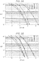
- FIG. 2(A) illustrates the BER characteristic of a Max-log-APP (APP: A Posterior Probability) in which iterative detection is not performed (see NPLs 1 and 2)
- FIG. 2(B) illustrates the BER characteristic of the Max-log-APP in which the iterative detection is performed (a number of iterations is 5) (see NPLs 1 and 2).
- the reception quality degrades with increasing Rician factor. This shows that the spatially multiplexed MIMO system has a unique problem that "in the spatially multiplexed MIMO system, the reception quality degrades when the propagation environment is stabilized" unlike the conventional system that transmits the single modulated signal.
- the broadcasting or the multi-cast communication is a service that needs to cope with various propagation environments, and the radio wave propagation environment between a receiver owned by a user and a broadcasting station can be the LOS environment.
- the service may be unavailable due to the degradation of the reception quality even if the radio wave has high reception field intensity in the receiver. That is, in order to use the spatially multiplexed MIMO system in the broadcasting or the multi-cast communication, there is a demand for development of the MIMO transmission scheme in which a certain level of reception quality is obtained in both the NLOS environment and the LOS environment.
- NPL 8 describes a method for selecting a code book used in pre-coding (pre-coding matrix (also referred to as a pre-coding weight matrix)) from feedback information from a communication partner. However, NPL 8 does not describe the method for performing the pre-coding in a situation in which the feedback information from the communication partner cannot be obtained like the broadcasting or the multi-cast communication as described above.
- pre-coding matrix also referred to as a pre-coding weight matrix
- NPL 4 describes a method for switching the pre-coding matrix with time, the method being applicable to the case that the feedback information does not exist.
- a unitary matrix is used as a matrix used in the pre-coding, and the unitary matrix is randomly switched.
- NPL 4 which describes the random switching, does not describe a method applicable to the degradation of the reception quality in the LOS environment.
- Neither description about the pre-coding method for improving the degradation of the reception quality in the LOS environment nor a method for constructing the pre-coding matrix is described in NPL 4.
- there is no description about a signal point arrangement (mapping) in the in-phase I-orthogonal Q plane of the modulation scheme in applying the pre-coding particularly a mapping method for improving the data reception quality in the LOS environment.
- the present disclosure relates to a transmission method for improving the quality of the received data in the reception device when the MIMO (Multiple-Input Multiple-Output) scheme involving the plurality of transmit antennas and the plurality of receive antennas is used in the multi-cast transmission or the broadcasting.
- MIMO Multiple-Input Multiple-Output
- mapping method (a signal point arrangement in an in-phase I-orthogonal Q plane of a modulation scheme) according to the exemplary embodiment will be described with 16QAM, 64QAM, and 256QAM mapping methods as an example.
- the 16QAM mapping method will be described below.
- FIG. 3 illustrates an example of a 16QAM signal point arrangement in the in-phase I-orthogonal Q plane.
- 16 marks "O" indicate 16QAM signal points
- a horizontal axis indicates I
- a vertical axis indicates Q.
- coordinates of the 16 signal points (in FIG. 3 , the mark "O" indicates the signal point) for 16QAM are expressed as follows: (3 ⁇ 16a ,3 ⁇ w 16a ),(3 ⁇ w 16a ,f ⁇ w 16a ),(3 ⁇ 16a ,-f ⁇ w 16a ),(3 ⁇ w 16a ,-3 ⁇ w 16a ),(f ⁇ w 16a ,3 ⁇ w 16 ),(f ⁇ w 16 a ,f ⁇ w 16a ),(f ⁇ w 16a ,-f ⁇ w 16a ),(f ⁇ w 16a ,-3 ⁇ w 16a ),(-f ⁇ w 16a ,3 ⁇ w 16a ),(-f ⁇ w 16a ,f ⁇ w 16a ),(-f ⁇ w 16a ,-f ⁇ w 16a ),(-f ⁇ w 16a ,-3 ⁇ w 16a ),(-3 ⁇ w 16a ,3 ⁇ w 16a ),(-3 ⁇ w 16a ),(-3 ⁇ w 16a ,(-3 ⁇ w 16
- the bits to be transmitted are set to b0, b1, b2, and b3.
- in-phase component I and orthogonal component Q of the post-mapping baseband signal are decided based on the bits to be transmitted (b0,b1,b2,b3).
- An example of a relationship between a set of b0, b1, b2, and b3 (0000 to 1111) and the coordinates of the signal point is indicated in FIG. 3 .
- the values of the sets of b0, b1, b2, and b3 (0000 to 1111) are indicated immediately below the 16 signal points (the marks "O" in FIG.
- the coordinates in the in-phase I-orthogonal Q plane of the signal point ("O") immediately above the set of b0, b1, b2, and b3 (0000 to 1111) serve as in-phase component I and orthogonal component Q of the post-mapping baseband signal.
- the relationship between the set of b0, b1, b2, and b3 (0000 to 1111) in 16QAM and the coordinates of the signal point is not limited to that illustrated in FIG. 3 .
- an average power of the post-mapping baseband signal is z 2 .
- the 16QAM mapping method is generally called non-uniform 16QAM.
- the mapping method is referred to as "16QAM mapping method #1".
- mapping method #0 16QAM mapping method
- the 16QAM mapping method will be described below.
- FIG. 4 illustrates an example of the 16QAM signal point arrangement in the in-phase I-orthogonal Q plane.
- the 16 marks "O" indicate the 16QAM signal points
- the horizontal axis indicates I
- the vertical axis indicates Q.
- coordinates of the 16 signal points (in FIG. 4 , the mark "O" indicates the signal point) for 16QAM are expressed as follows: (3 ⁇ w 16b ,3 ⁇ w 16b ),(3 ⁇ w 16b ,f 2 ⁇ w 16b ),(3 ⁇ w 16b ,-f 2 ⁇ w 16b ),(3 ⁇ w 16b ,-3 ⁇ w 16b ),(f 1 ⁇ w 16b ,3 ⁇ w 16b ),(f 1 ⁇ w 16b ,f 2 ⁇ w 16b ),(f 1 ⁇ w 16b ,-f 2 ⁇ w 16b ),(f 1 ⁇ w 16b ,-3 ⁇ w 16b ),(-f 1 ⁇ w 16b ,3 ⁇ w 16b ),(-f 1 ⁇ w 16b ,3 ⁇ w 16b ),(-f 1 ⁇ w 16b ,f 2 ⁇ w 16b ),(-f 1 ⁇ w 16b ,-f 2 ⁇ w 16b ),(-f 1 ⁇
- the bits (input bits) to be transmitted are set to b0, b1, b2, and b3.
- in-phase component I and orthogonal component Q of the post-mapping baseband signal are decided based on the bits to be transmitted (b0,b1,b2,b3).
- An example of the relationship between a set of b0, b1, b2, and b3 (0000 to 1111) and the coordinates of the signal point is indicated in FIG. 4 .
- the values of the sets of b0, b1, b2, and b3 (0000 to 1111) are indicated immediately below the 16 signal points (the marks "O"in FIG.
- the coordinates in the in-phase I-orthogonal Q plane of the signal point ("O") immediately above the set of b0, b1, b2, and b3 (0000 to 1111) serve as in-phase component I and orthogonal component Q of the post-mapping baseband signal.
- the relationship between the set of b0, b1, b2, and b3 (0000 to 1111) in 16QAM and the coordinates of the signal point is not limited to that illustrated in FIG. 4 .
- an average power of the post-mapping baseband signal is z 2 .
- 16QAM mapping method #2 the 16QAM mapping method is referred to as "16QAM mapping method #2".
- the 16QAM mapping method will be described below.
- FIG. 5 illustrates an example of the 16QAM signal point arrangement in the in-phase I-orthogonal Q plane.
- the 16 marks "O" indicate the 16QAM signal points
- the horizontal axis indicates I
- the vertical axis indicates Q.
- coordinates of the 16 signal points (in FIG. 5 , the mark "O" indicates the signal point) for 16QAM are expressed as follows: (k 1 ⁇ w 16c ,k 2 ⁇ w 16c ),(k 1 ⁇ w 16c ,1 ⁇ w 16c ),(k 1 ⁇ w 16c ,-1 ⁇ w 16c ),(k 1 ⁇ w 16c ,-k 2 ⁇ w 16c ),(1 ⁇ w 16c ,k 2 ⁇ w 16c ),(1 ⁇ w 16c ,1 ⁇ w 16c ),(1 ⁇ w 16b ,-1 ⁇ w 16c ),(1 ⁇ w 16c ,-k 2 ⁇ w 16c ),(-1 ⁇ w 16c ,k 2 ⁇ w 16c ),(-1 ⁇ w 16c ,1 ⁇ w 16c ),(-1 ⁇ w 16c ,-1 ⁇ w 16c ),(-1 ⁇ w 16c ,-k 2 ⁇ w 16c ),(-k 1 ⁇ w 16c ),(-1 ⁇ w 16c
- the bits (input bits) to be transmitted are set to b0, b1, b2, and b3.
- in-phase component I and orthogonal component Q of the post-mapping baseband signal are decided based on the bits to be transmitted (b0,b1,b2,b3).
- An example of the relationship between a set of b0, b1, b2, and b3 (0000 to 1111) and the coordinates of the signal point is indicated in FIG. 5 .
- the values of the sets of b0, b1, b2, and b3 (0000 to 1111) are indicated immediately below the 16 signal points (the marks "O"in FIG.
- the coordinates in the in-phase I-orthogonal Q plane of the signal point ("O") immediately above the set of b0, b1, b2, and b3 (0000 to 1111) serve as in-phase component I and orthogonal component Q of the post-mapping baseband signal.
- the relationship between the set of b0, b1, b2, and b3 (0000 to 1111) in 16QAM and the coordinates of the signal point is not limited to that illustrated in FIG. 5 .
- an average power of the post-mapping baseband signal is z 2 .
- 16QAM mapping method #3 the 16QAM mapping method is referred to as "16QAM mapping method #3".
- the 64QAM mapping method will be described below.
- FIG. 6 illustrates an example of a 64QAM signal point arrangement in the in-phase I-orthogonal Q plane.
- the 64 marks "O" indicate the 64QAM signal points
- the horizontal axis indicates I
- the vertical axis indicates Q.
- the bits (input bits) to be transmitted are set to b0, b1, b2, b3, b4, and b5.
- in-phase component I and orthogonal component Q of the post-mapping baseband signal are decided based on the bits to be transmitted (b0,b1,b2,b3,b4,b5).
- An example of the relationship between a set of b0, b1, b2, b3, b4, and b5 (000000 to 111111) and the coordinates of the signal point is indicated in FIG. 6 .
- the values of the sets of b0, b1, b2, b3, b4, and b5 (000000 to 111111) are indicated immediately below the 64 signal points (in FIG. 6 , the marks "O") of 64QAM:
- an average power of the post-mapping baseband signal is z 2 .
- the 64QAM mapping method is generally called non-uniform 64QAM.
- the mapping method is referred to as "64QAM mapping method #1".
- mapping method #0 The mapping method in the case of "(g 1 ,g 2 ,g 3 ) ⁇ (1,3,5)" in the above description is referred to as uniform 64QAM, and is hereinafter referred to as "64QAM mapping method #0".
- FIG. 7 illustrates an example of the 64QAM signal point arrangement in the in-phase I-orthogonal Q plane.
- the 64 marks "O" indicate the 64QAM signal points
- the horizontal axis indicates I
- the vertical axis indicates Q.
- g 1 > 0 (g 1 is a real number greater than 0) and g 2 > 0 (g 2 is a real number greater than 0) and g 3 > 0 (g 3 is a real number greater than 0) and g 4 > 0 (g 4 is a real number greater than 0) and g 5 > 0 (g 5 is a real number greater than 0) and g 6 > 0 (g 6 is a real number greater than 0) hold, and ⁇ g 1 ⁇ 7 and g 2 ⁇ 7 and g 3 ⁇ 7 and g 1 ⁇ g 2 and g 1 ⁇ g 3 and g 2 ⁇ g 3 ⁇ and ⁇ g 4 ⁇ 7 and g 5 ⁇ 7 and g 6 ⁇ 7 and g 4 ⁇ g 5 and g 4 ⁇ g 6 and g 5 ⁇ g 6 ⁇ and ⁇ g 1 ⁇ g 4 or g 2 ⁇ g 5 or g 3 ⁇ ⁇ g 1 ⁇
- the bits (input bits) to be transmitted are set to b0, b1, b2, b3, b4, and b5.
- in-phase component I and orthogonal component Q of the post-mapping baseband signal are decided based on the bits to be transmitted (b0,b1,b2,b3,b4,b5).
- An example of the relationship between a set of b0, b1, b2, b3, b4, and b5 (000000 to 111111) and the coordinates of the signal point is indicated in FIG. 7 .
- the values of the sets of b0, b1, b2, b3, b4, and b5 (000000 to 111111) are indicated immediately below the 64 signal points (the marks "O" in FIG. 7 ) of 64QAM:
- an average power of the post-mapping baseband signal is z 2 .
- 64QAM mapping method #2 the 64QAM mapping method is referred to as "64QAM mapping method #2".
- FIG. 8 illustrates an example of the 64QAM signal point arrangement in the in-phase I-orthogonal Q plane.
- the 64 marks "O" indicate the 64QAM signal points
- the horizontal axis indicates I
- the vertical axis indicates Q.
- the bits (input bits) to be transmitted are set to b0, b1, b2, b3, b4, and b5.
- in-phase component I and orthogonal component Q of the post-mapping baseband signal are decided based on the bits to be transmitted (b0,b1,b2,b3,b4,b5).
- An example of the relationship between a set of b0, b1, b2, b3, b4, and b5 (000000 to 111111) and the coordinates of the signal point is indicated in FIG. 8 .
- the values of the sets of b0, b1, b2, b3, b4, and b5 (000000 to 111111) are indicated immediately below the 64 signal points (in FIG. 8 , the marks "O") of 64QAM:
- an average power of the post-mapping baseband signal is z 2 .
- 64QAM mapping method #3 the 64QAM mapping method is referred to as "64QAM mapping method #3".
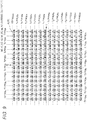
- FIG. 9 illustrates an example of a 256QAM signal point arrangement in the in-phase I-orthogonal Q plane.
- the 256 marks "O" indicate the 256QAM signal points
- the horizontal axis indicates I
- the vertical axis indicates Q.
- the bits (input bits) to be transmitted are set to b0, b1, b2, b3, b4, b5, b6, and b7.
- in-phase component I and orthogonal component Q of the post-mapping baseband signal are decided based on the bits to be transmitted (b0,b1,b2,b3,b4,b5,b6,b7).
- FIG. 9 illustrates an example of the relationship between a set of b0, b1, b2, b3, b4, b5, b6, and b7 (00000000 to 11111111) and the coordinates of the signal point.
- the values of the sets of b0, b1, b2, b3, b4, b5, b6, and b7 are indicated immediately below the 256 signal points (in FIG. 9 , the marks "O") of 256QAM:
- an average power of the post-mapping baseband signal is z 2 .
- the 256QAM mapping method is generally called non-uniform 256QAM.
- the mapping method is referred to as "256QAM mapping method #1".
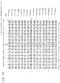
- FIG. 10 illustrates an example of the 256QAM signal point arrangement in the in-phase I-orthogonal Q plane.
- the 256 marks " ⁇ " indicate the 256QAM signal points
- the horizontal axis indicates I
- the vertical axis indicates Q.
- the bits (input bits) to be transmitted are set to b0, b1, b2, b3, b4, b5, b6, and b7.
- in-phase component I and orthogonal component Q of the post-mapping baseband signal are decided based on the bits to be transmitted (b0,b1,b2,b3,b4,b5,b6,b7).
- An example of the relationship between a set of b0, b1, b2, b3, b4, b5, b6, and b7 (00000000 to 11111111) and the coordinates of the signal point is indicated in FIG. 10 .
- the values of the sets of b0, b1, b2, b3, b4, b5, b6, and b7 are indicated immediately below the 256 signal points (the marks " ⁇ " in FIG. 10 ) of 256QAM:
- an average power of the post-mapping baseband signal is z 2 .
- 256QAM mapping method #2 the 256QAM mapping method is referred to as "256QAM mapping method #2".
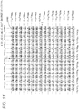
- FIG. 11 illustrates an example of the 256QAM signal point arrangement in the in-phase I-orthogonal Q plane.
- the 256 marks " ⁇ " indicate the 256QAM signal points
- the horizontal axis indicates I
- the vertical axis indicates Q.
- the bits (input bits) to be transmitted are set to b0, b1, b2, b3, b4, b5, b6, and b7.
- in-phase component I and orthogonal component Q of the post-mapping baseband signal are decided based on the bits to be transmitted (b0, b1, b2, b3, b4, b5, b6, b7).
- An example of the relationship between a set of b0, b1, b2, b3, b4, b5, b6, and b7 (00000000 to 11111111) and the coordinates of the signal point is indicated in FIG. 11 .
- the values of the sets of b0, b1, b2, b3, b4, b5, b6, and b7 are indicated immediately below the 256 signal points (the marks " ⁇ "in FIG. 11 ) of 256QAM:
- an average power of the post-mapping baseband signal is z 2 .
- 256QAM mapping method #3 the 256QAM mapping method is referred to as "256QAM mapping method #3".
- mapping method in each modulation scheme is as described above. Detailed usage of the method in the transmission device is described later.
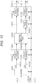
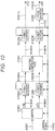
- data H1001 obtained by performing pieces of processing such as error correction coding and interleaving (data rearrangement) and control signal H1012 are input to mapper H1002, and mapper H1002 sets an s1 modulation scheme and an s2 modulation scheme based on control signal H1012, performs the mapping for s1 and s2, and outputs post-mapping signal s1(t) (H1003A) and post-mapping signal s2(t) (H1003B) (s1(t) and s2(t) are complex numbers).
- t represents time.
- s1 and s2 may be a function of frequency f or a function of time t and frequency f (accordingly, the output may be expressed as s1(f) and s2(f) or s1(t,f) and s2(t,f)). In this case, for example, it is assumed that the output is the function of time t.
- Post-power-change signal H1005A (x1(t)), post-power-change signal H1005B (x2(t)), and control signal H1012 are input to weighting composition part H1006, and weighting composition part H1006 sets 2 ⁇ 2 matrix (pre-coding matrix) W including a complex number as an element based on control signal H1012, multiplies matrix W by post-power-change signal H1005A (x1(t)) and post-power-change signal H1005B (x2(t)) (pre-coding), and outputs post-weighting-composition signal z1'(t) (H1007A) and post-weighting-composition signal z2'(t) (H1007B).
- Post-weighting-composition signal z1'(t) (H1007A) and post-weighting-composition signal z2'(t) (H1007B) are given by the following equation.
- [Mathematical formula 11] z 1 ′ t z 2 ′ t w 11 w 12 w 12 w 22 x 1 t x 2 t
- Post-weighting-composition signal z2'(t) (H1007B) and control signal H1012 are input to phase changer H1008, and phase changer H1008 sets regularly changing phase change value ⁇ (t) based on control signal H1012, performs a phase change on post-weighting-composition signal z2'(t) (H1007B), and outputs post-phase-change signal H1009 (z2"(t)).
- post-phase-change signal H1009 (z2"(t)) is given by the following equation.
- [Mathematical formula 12] z 2 " t e jO t ⁇ z 2 ′ t j is an imaginary unit.
- ⁇ (t) is dealt with as the function of time t, ⁇ may be the function of frequency f or the function of frequency f and time t. The phase change is described later.
- FIG. 13 illustrates the configuration at that time. The detailed description of the transmission device in FIG. 13 is omitted because the transmission device in FIG. 13 performs (Equation 14) similarly to the transmission device in FIG. 12 .
- phase changer H1008 performs the phase change on the input signal and outputs the post-phase-change signal
- power changer H1010B performs the power change on the input signal and outputs the post-power-change signal.
- z1(t) and z2(t) are transmitted from different antennas at the same clock time and the same frequency (common frequency).
- z1(t) and z2(t) are the functions of time t
- z1(t) and z2(t) may be the function of frequency f or the function of time t and frequency f
- the output may be expressed as z1(f) and z2(f) or z1(t,f) and z2(t,f)). In this case, for example, it is assumed that the output is the function of time t.
- z1(t), z2(t), z1'(t), z2'(t), and z2"(t) are also the function of time t.
- z1(t), z2(t), z1'(t), z2'(t), and z2"(t) may be the function of frequency f or the function of time t and frequency f.
- FIG. 14 illustrates a configuration of signal processing after the signal processing in FIG. 12 or 13 is performed.
- Modulated signal H1221A, pilot symbol signal H1222A, control information symbol signal H1223A, and control signal H1212 are input to inserter H1224A, and inserter H1224A generates baseband signal H1225A based on a frame configuration from modulated signal H1221A, pilot symbol signal H1222A, and control information symbol signal H1223A based on information about the transmission method and frame configuration included in control signal H1212, and outputs baseband signal H1225A.
- Modulated signal H1221A corresponds to z1(t) in FIG. 12 or 13 .
- modulated signal H1221B, pilot symbol signal H1222B, control information symbol signal H1223B, and control signal H1212 are input to inserter H1224B, and inserter H1224B generates baseband signal H1225B based on a frame configuration from modulated signal H1221B, pilot symbol signal H1222B, and control information symbol signal H1223B based on information about the transmission method and frame configuration included in control signal H1212, and outputs baseband signal H1225B.
- Modulated signal H1221B corresponds to z2(t) in FIG. 12 or 13 .
- Baseband signal H1225A and control signal H1212 are input to radio part H1226A, radio part H1226A generates transmission signal H1226A by performing an inverse Fourier transform or pieces of processing such as an orthogonal modulation, frequency conversion, and amplification based on control signal H1212 when, for example, an OFDM (Orthogonal Frequency Division Multiplexing) scheme is used, and radio part H1226A outputs transmission signal H1226A.
- Transmission signal H1226A is output from antenna H1228A as a radio wave.
- baseband signal H1225B and control signal H1212 are input to radio part H1226B, radio part H1226B generates transmission signal H1226B by performing the inverse Fourier transform or the pieces of processing such as the orthogonal modulation, the frequency conversion, and the amplification based on control signal H1212 when, for example, the OFDM scheme is used, and radio part H1226B outputs transmission signal H1226B.
- Transmission signal H1226B is output from antenna H1228B as a radio wave.
- FIG. 15 illustrates an example of a frame configuration of modulated signals which are transmitted through antennas, including z1(t) and z2(t) in FIGS. 12 and 13 .
- the horizontal axis indicates the frequency (carrier), and the vertical axis indicates the time.
- the control information symbol is not illustrated in the frame configuration of FIG. 15 .
- FIG. 15 illustrates the frame configuration of carrier 1 to carrier 36 and clock time $1 to clock time $11.
- H1301 designates a pilot symbol (conforming to a rule of group 1)
- H1302 designates a pilot symbol (conforming to a rule of group 2)
- H1303 designates a data symbol.
- Transmission signal H1227A in FIG. 14 has the frame configuration as illustrated in FIG. 15 , and transmits symbols including the data symbols and pilot symbol.
- data symbol H1303 is the symbol corresponding to z1(t), and includes an s1(t) component and an s2(t) component (however, sometimes data symbol H1303 includes only one of the s1(t) component and the s2(t) component depending on the pre-coding matrix).
- Transmission signal H1227B in FIG. 14 has the frame configuration as illustrated in FIG. 15 , and transmits symbols including the data symbols and pilot symbol.
- data symbol H1303 is the symbol corresponding to z2(t), and includes the s1(t) component and the s2(t) component (however, sometimes data symbol H1303 includes only one of the s1(t) component and the s2(t) component depending on the pre-coding matrix).
- pilot symbol in the frame configuration of transmission signal H1227A and the pilot symbol in the frame configuration of transmission signal H1227B have the same configuration (have the same in-phase component and the same orthogonal component), but each of transmission signals H1227A and H1227B includes the pilot symbol conforming to a certain rule.
- the frame configuration is not limited to that illustrated in FIG. 15 , but may include a control information symbol including information on the transmission method, the modulation scheme, and the error correction method.
- transmission signal H1227B transmits the null symbol using a carrier in which transmission signal H1227A transmits the pilot symbol at a clock time at which transmission signal H1227A transmits the pilot symbol.
- transmission signal H1227A transmits the null symbol using a carrier in which transmission signal H1227B transmits the pilot symbol at a clock time at which transmission signal H1227B transmits the pilot symbol.
- the pilot symbol may have another different configuration. It is necessary to obtain a channel fluctuation of transmission signal H1227A and a channel fluctuation of transmission signal H1227B in the reception device.
- FIG. 16 illustrates a relationship between the transmission device and the reception device of the exemplary embodiment. The operation of the transmission device is described above. The operation of the reception device will be described below.
- the reference mark H1401 designates the transmission device
- the reference mark H1402 designates the reception device.
- r1 is a reception signal of antenna RX1 of the reception device
- r2 is a reception signal of antenna RX2
- h1 1, h12, h21, and h22 are a factor of radio wave propagation (channel fluctuation) between the antennas of the transmitter and receiver
- n1 and n2 are noises.
- each variable is the function of time t.
- each variable may be the function of frequency f or the function of time t and frequency f (in this case, each variable is the function of time t by way of example).
- Channel estimator H1403A in FIG. 16 estimates h11(t) and h12(t) in (Equation 15). The values of h11(t) and h12(t) are estimated using, for example, the pilot symbol in FIG. 15 .
- Channel estimator H1403B in FIG. 16 estimates h21(t) and h22(t) in (Equation 15). The values of h21(t) and h22(t) are estimated using, for example, the pilot symbol in FIG. 15 .
- Signal processor H1404 in FIG. 16 obtains a logarithmic likelihood ratio of each bit of the data transmitted by the transmission device using the relationship of (Equation 15). Then, signal processor H1404 performs pieces of processing such as deinterleaving and error correction decoding to obtain reception information.
- Equation 12 a way to provide ⁇ (t) in (Equation 12) will be described. It is assumed that i (i is an integer of 0 or more) is a symbol number. At this point, it is assumed that N (N is an integer of 2 or more) kinds of phase values are provided as a value that can be taken by ⁇ (i). At this point, the N kinds of phase values are expressed by Phase[k] (k is an integer of 0 to N-1 and 0 radian ⁇ Phase[k] ⁇ 2 ⁇ radian). It is assumed that all the N kinds of phase values of Phase[k] are used in ⁇ (i). It is necessary that the following condition hold in order that the reception device obtains the high data reception quality.
- Phase[x] ⁇ Phase[y] holds in all integers x and y satisfying these assumptions.
- Phase[x+2] - Phase[x+1] Phase[x+1] - Phase[x] holds in all integers x satisfying the assumption (however, even if ⁇ Condition #2> is not satisfied, there is a possibility that the reception device obtains the high data reception quality).
- ⁇ (i) Phase[i mod N].
- mod is modulo, and therefore "i mod N" means a remainder when i is divided by N.
- mapping of s1 and s2 in FIGS. 12 and 13 will be described below.
- 16QAM mapping method #0 "16QAM mapping method #1", “16QAM mapping method #2”, and “16QAM mapping method #3" are described above as the 16QAM mapping method.
- M kinds of 16QAM signal point arrangement methods belonging to one of "16QAM mapping method #0", “16QAM mapping method #1”, “16QAM mapping method #2”, and “16QAM mapping method #3” are prepared (M is an integer of 2 or more) (in the transmission device). At this point, the following condition is satisfied.
- M kinds of 16QAM mapping are expressed as "16QAM signal point arrangement $k". Assuming that (k is an integer of 0 to M-1), the following condition is satisfied.
- mapping set is defined.
- mapping set is defined as "(s1(t) 16QAM signal point arrangement $p 1 ,s2(t) 16QAM signal point arrangement $p 2 )".
- the different mapping set means that the following matter holds.
- the transmission device (the mapper in FIGS. 12 and 13 ) prepares L (L is an integer of 2 or more) kinds of mapping sets, and sets the L kinds of mapping sets to "mapping set *k" (k is an integer of 0 to L-1). At this point, the following condition is satisfied.
- mapping set *x differs from “mapping set *y” in all integers x and y satisfying these conditions.
- phase changer (subsequent to the weighting composition part) in FIG. 12 or 13 (or FIG. 18 , 19 , 20 , or 21 ) performs the phase change on the signal generated using s1 and s2 generated using "mapping set *x". At this point, it is assumed that all the N kinds of phase values of Phase[k] are used as phase change value ⁇ . ⁇
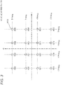
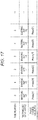
- FIG. H15 illustrates the case that ⁇ Condition #6> is satisfied.
- the horizontal axis indicates time number (slot number) i.
- mapping set *0 In time number 0, the mapper in FIG. 12 or 13 performs the mapping using "mapping set *0", and the phase changer performs the phase change using Phase[0].
- the mapper in FIG. 12 or 13 performs the mapping using "mapping set *0", and the phase changer performs the phase change using Phase[1].
- mapping set *1 Attention is paid to "mapping set *1".
- the mapper in FIG. 12 or 13 performs the mapping using "mapping set *1"
- the phase changer performs the phase change using Phase[0].
- the mapper in FIG. 12 or 13 performs the mapping using "mapping set *1", and the phase changer performs the phase change using Phase[1].
- mapping set *2 Attention is paid to "mapping set *2".
- the mapper in FIG. 12 or 13 performs the mapping using "mapping set *2", and the phase changer performs the phase change using Phase[0].
- the mapper in FIG. 12 or 13 performs the mapping using "mapping set *2", and the phase changer performs the phase change using Phase[1].
- phase changer (subsequent to the weighting composition part) in FIG. 12 or 13 (or FIG. 18 , 19 , 20 , or 21 ) performs the phase change on the signal generated using s1 and s2 generated using "mapping set *x". At this point, it is assumed that all the N kinds of phase values of Phase[k] are used as phase change value ⁇ . ⁇
- 64QAM mapping method #0 "64QAM mapping method #1", “64QAM mapping method #2”, and “64QAM mapping method #3" are described above as 64QAM mapping method.
- M kinds of 64QAM signal point arrangement methods belonging to one of "64QAM mapping method #0", “64QAM mapping method #1”, “64QAM mapping method #2”, and “64QAM mapping method #3” are prepared (M is an integer of 2 or more) (in the transmission device). At this point, the following condition is satisfied.
- the M kinds of 64QAM mapping are expressed as "64QAM signal point arrangement $k". Assuming that (k is an integer of 0 to M-1), the following condition is satisfied.
- mapping set is defined.
- mapping set is defined as "(s1(t) 64QAM signal point arrangement $p 1 ,s2(t) 64QAM signal point arrangement $p 2 )".
- the different mapping set means that the following matter holds.
- the transmission device (the mapper in FIGS. 12 and 13 ) prepares L (L is an integer of 2 or more) kinds of mapping sets, and sets the L kinds of mapping sets to "mapping set *k" (k is an integer of 0 to L-1). At this point, the following condition is satisfied.
- mapping set *x differs from “mapping set *y” in all integers x and y satisfying these conditions.
- phase changer (subsequent to the weighting composition part) in FIG. 12 or 13 (or FIG. 18 , 19 , 20 , or 21 ) performs the phase change on the signal generated using s1 and s2 generated using "mapping set *x". At this point, it is assumed that all the N kinds of phase values of Phase[k] are used as phase change value ⁇ . ⁇
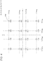
- FIG. 17 illustrates the case that ⁇ Condition #11> is satisfied.
- the horizontal axis indicates time number (slot number) i.
- mapping set *0 In time number 0, the mapper in FIG. 12 or 13 performs the mapping using "mapping set *0", and the phase changer performs the phase change using Phase[0].
- the mapper in FIG. 12 or 13 performs the mapping using "mapping set *0", and the phase changer performs the phase change using Phase[1].
- mapping set *1 Attention is paid to "mapping set *1".
- the mapper in FIG. 12 or 13 performs the mapping using "mapping set *1"
- the phase changer performs the phase change using Phase[0].
- the mapper in FIG. 12 or 13 performs the mapping using "mapping set *1", and the phase changer performs the phase change using Phase[1].
- mapping set *2 Attention is paid to "mapping set *2".
- the mapper in FIG. 12 or 13 performs the mapping using "mapping set *2", and the phase changer performs the phase change using Phase[0].
- the mapper in FIG. 12 or 13 performs the mapping using "mapping set *2", and the phase changer performs the phase change using Phase[1].
- phase changer (subsequent to the weighting composition part) in FIG. 12 or 13 (or FIG. 18 , 19 , 20 , or 21 ) performs the phase change on the signal generated using s1 and s2 generated using "mapping set *x". At this point, it is assumed that all the N kinds of phase values of Phase[k] are used as phase change value ⁇ . ⁇
- 256QAM mapping method #0 "256QAM mapping method #1", “256QAM mapping method #2”, and "256QAM mapping method #3" are described above as 256QAM mapping method.
- M kinds of 256QAM signal point arrangement methods belonging to one of "256QAM mapping method #0", "256QAM mapping method #1", “256QAM mapping method #2”, and “256QAM mapping method #3" are prepared (M is an integer of 2 or more) (in the transmission device). At this point, the following condition is satisfied.
- the M kinds of 256QAM mapping are expressed as "256QAM signal point arrangement $k". Assuming that (k is an integer of 0 to M-1), the following condition is satisfied.
- mapping set is defined.
- mapping set is defined as "(s1(t) 256QAM signal point arrangement $p 1 ,s2(t) 256QAM signal point arrangement $p 2 )".
- the different mapping set means that the following matter holds.
- the transmission device (the mapper in FIGS. 12 and 13 ) prepares L (L is an integer of 2 or more) kinds of mapping sets, and sets the L kinds of mapping sets to "mapping set *k" (k is an integer of 0 to L-1). At this point, the following condition is satisfied.
- mapping set *x differs from “mapping set *y” in all integers x and y satisfying these conditions.
- phase changer (subsequent to the weighting composition part) in FIG. 12 or 13 (or FIG. 18 , 19 , 20 , or 21 ) performs the phase change on the signal generated using s1 and s2 generated using "mapping set *x". At this point, it is assumed that all the N kinds of phase values of Phase[k] are used as phase change value ⁇ . ⁇
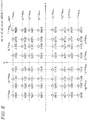
- the horizontal axis indicates time number (slot number) i.
- mapping set *0 In time number 0, the mapper in FIG. 12 or 13 performs the mapping using "mapping set *0", and the phase changer performs the phase change using Phase[0].
- the mapper in FIG. 12 or 13 performs the mapping using "mapping set *0", and the phase changer performs the phase change using Phase[1].
- mapping set *1 Attention is paid to "mapping set *1".
- the mapper in FIG. 12 or 13 performs the mapping using "mapping set *1"
- the phase changer performs the phase change using Phase[0].
- the mapper in FIG. 12 or 13 performs the mapping using "mapping set *0", and the phase changer performs the phase change using Phase[1].
- mapping set *2 Attention is paid to "mapping set *2".
- the mapper in FIG. 12 or 13 performs the mapping using "mapping set *2", and the phase changer performs the phase change using Phase[0].
- the mapper in FIG. 12 or 13 performs the mapping using "mapping set *2", and the phase changer performs the phase change using Phase[1].
- phase changer (subsequent to the weighting composition part) in FIG. 12 or 13 (or FIG. 18 , 19 , 20 , or 21 ) performs the phase change on the signal generated using s1 and s2 generated using "mapping set *x". At this point, it is assumed that all the N kinds of phase values of Phase[k] are used as phase change value ⁇ . ⁇
- the transmission device that transmits the modulated signal which is generated through the configuration in FIG. 14 using z1(t) and z2(t) generated in FIG. 12 or 13 , is described above.
- the transmission device may transmit the modulated signal that is generated through the configuration in FIG. 14 using z1(t) and z2(t) generated in FIG. 18 , 19 , 20 , or 21 instead of FIG. 12 or 13 .
- Configurations in FIG. 18 , 19 , 20 , and 21 will be described below.
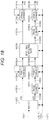
- FIG. 18 the component operated similarly to that in FIG. 12 is designated by the same reference mark.
- data H1001 obtained by performing pieces of processing such as error correction coding and interleaving (data rearrangement) and control signal H1012 are input to mapper H1002, and mapper H1002 sets an s1 modulation scheme and an s2 modulation scheme based on control signal H1012, performs the mapping for s1 and s2, and outputs post-mapping signal s1(t) (H1003A) and post-mapping signal s2(t) (H1003B) (s1(t) and s2(t) are complex numbers).
- t represents time.
- s1 and s2 may be a function of frequency f or a function of time t and frequency f (accordingly, the output may be expressed as s1(f) and s2(f) or s1(t,f) and s2(t,f)). In this case, for example, it is assumed that the output is the function of time t.
- Post-mapping signal s2(t) (H1003B) and control signal H1012 are input to phase changer H1601, and phase changer H1601 sets regularly changing phase change value ⁇ (t) based on control signal H1012, performs the phase change on post-mapping signal s2(t) (H1003B), and outputs post-phase-change signal H1602 (s2'(t)).
- post-phase-change signal H1602 (s2'(t)) is given by the following equation.
- [Mathematical formula 16] s 2 ′ t e j ⁇ t ⁇ s 2 t j is an imaginary unit.
- ⁇ (t) is dealt with as the function of time t, ⁇ may be the function of frequency f or the function of frequency f and time t. The phase change is described later.
- Post-power-change signal H1005A (x1(t)), post-power-change signal H1005B (x2(t)), and control signal H1012 are input to weighting composition part H1006, and weighting composition part H1006 sets 2 ⁇ 2 matrix (pre-coding matrix) W including a complex number as an element based on control signal H1012, multiplies matrix W by post-power-change signal H1005A (x1(t)) and post-power-change signal H1005B (x2(t)) (pre-coding), and outputs post-weighting-composition signal z1'(t) (H1007A) and post-weighting-composition signal z2'(t) (H1007B).
- Post-weighting-composition signal z1'(t) (H1007A) and post-weighting-composition signal z2'(t) (H1007B) are given by the following equation.
- [Mathematical formula 18] z 1 ′ t z 2 ′ t w 11 w 12 w 21 w 22 x 1 t x 2 t
- Post-weighting-composition signal z2'(t) (H1007B) and control signal H1012 are input to phase changer H1008, and phase changer H1008 sets regularly changing phase change value ⁇ (t) based on control signal H1012, performs a phase change on post-weighting-composition signal z2'(t) (H1007B), and outputs post-phase-change signal H1009 (z2"(t)).
- post-phase-change signal H1009 (z2"(t)) is given by the following equation.
- [Mathematical formula 19] z 2 " t e j ⁇ t ⁇ z 2 ′ t j is an imaginary unit.
- ⁇ (t) is dealt with as the function of time t, ⁇ may be the function of frequency f or the function of frequency f and time t. The phase change is described later.
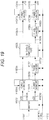
- FIG. 19 illustrates the configuration at that time.
- the detailed description of the transmission device in FIG. 19 is omitted because the transmission device in FIG. 19 performs (Equation 21) similarly to the transmission device in FIG. 18 .
- phase changer H1701 performs the phase change on the input signal and outputs the post-phase-change signal
- power changer H1004B performs the power change on the input signal and outputs the post-power-change signal.
- FIG. 20 illustrates the configuration at that time.
- the detailed description of the transmission device in FIG. 20 is omitted because the transmission device in FIG. 20 performs (Equation 22) similarly to the transmission device in FIG. 18 .
- phase changer H1801 performs the phase change on the input signal and outputs the post-phase-change signal
- power changer H1010B performs the power change on the input signal and outputs the post-power-change signal.
- Equation 20 (Equation 20), (Equation 21), and (Equation 22) are equivalent to (Equation 23).
- FIG. 21 illustrates the configuration at that time.
- the detailed description of the transmission device in FIG. 21 is omitted because the transmission device in FIG. 21 performs (Equation 23) similarly to the transmission device in FIG. 18 .
- phase changer H1901 performs the phase change on the input signal and outputs the post-phase-change signal
- power changer H1010B performs the power change on the input signal and outputs the post-power-change signal.
- z1(t) and z2(t) are transmitted from different antennas at the same clock time and the same frequency (common frequency).
- z1(t) and z2(t) are the functions of time t
- z1(t) and z2(t) may be the function of frequency f or the function of time t and frequency f
- the output may be expressed as z1(f) and z2(f) or z1(t,f) and z2(t,f)). In this case, for example, it is assumed that the output is the function of time t.
- z1(t), z2(t), z1'(t), z2'(t), and z2"(t) are also the function of time.
- z1(t), z2(t), z1'(t), z2'(t), and z2"(t) may be the function of frequency f or the function of time t and frequency f.
- FIG. 16 illustrates a relationship between the transmission device and the reception device in FIGS. 18 , 19 , 20 , and 21 .
- the operation of the transmission device is described above.
- the operation of the reception device will be described below.
- the reference mark H1401 designates the transmission device
- the reference mark H1402 designates the reception device.
- r1 is a reception signal of antenna RX1 of the reception device
- r2 is a reception signal of antenna RX2
- h11, h12, h21, and h22 are a factor of radio wave propagation (channel fluctuation) between the antennas of the transmitter and receiver
- n1 and n2 are noises.
- each variable is the function of time t.
- each variable may be the function of frequency f or the function of time t and frequency f (in this case, each variable is the function of time t by way of example).
- Channel estimator H1403A in FIG. 16 estimates h11(t) and h12(t) in (Equation 24). The values of h11(t) and h12(t) are estimated using, for example, the pilot symbol in FIG. 15 .
- Channel estimator H1403B in FIG. 16 estimates h21(t) and h22(t) in (Equation 24). The values of h21(t) and h22(t) are estimated using, for example, the pilot symbol in FIG. 15 .
- Signal processor H1404 in FIG. 16 obtains a logarithmic likelihood ratio of each bit of the data transmitted by the transmission device using the relationship of (Equation 24). Then, signal processor H1404 performs pieces of processing such as deinterleaving and error correction decoding to obtain reception information (see NPLs 5 and 6).
- ⁇ Condition #2> may be satisfied (however, even if ⁇ Condition #2> is not satisfied, there is some possibility that the reception device obtains the high data reception quality).
- ⁇ (i) Phase[i mod N].
- mod is modulo, and therefore "i mod N" means a remainder when i is divided by N.
- mapping of s1 and s2 in FIGS. 18 , 19 , 20 , and 21 will be described below.
- 16QAM mapping method #0 "16QAM mapping method #1", “16QAM mapping method #2”, and “16QAM mapping method #3" are described above as the 16QAM mapping method.
- mapping set is defined.
- mapping set is defined as "(s1(t) 16QAM signal point arrangement $p 1 ,s2(t) 16QAM signal point arrangement $p 2 )".
- the different mapping set means that the following matter holds.
- the transmission device (the mapper in FIGS. 18 , 19 , 20 , and 21 ) prepares L (L is an integer of 2 or more) kinds of mapping sets, and sets the L kinds of mapping sets to "mapping set *k" (k is an integer of 0 to L-1). At this point, ⁇ Condition #5> is satisfied.
- the horizontal axis indicates time number (slot number) i.
- mapping set *0 In time number 0, the mapper in FIG. 18 , 19 , 20 , or 21 performs the mapping using "mapping set *0", and phase changer H1008, H1801, or H1901 performs the phase change using Phase[0].
- the mapper in FIG. 18 , 19 , 20 , or 21 performs the mapping using "mapping set *0", and phase changer H1008, H1801, or H1901 performs the phase change using Phase[1].
- mapping set *1 Attention is paid to "mapping set *1".
- the mapper in FIG. 18 , 19 , 20 , or 21 performs the mapping using "mapping set *1", and phase changer H1008, H1801, or H1901 performs the phase change using Phase[0].
- the mapper in FIG. 18 , 19 , 20 , or 21 performs the mapping using "mapping set *0", and phase changer H1008, H1801, or H1901 performs the phase change using Phase[1].
- mapping set *2 Attention is paid to "mapping set *2".
- the mapper in FIG. 18 , 19 , 20 , or 21 performs the mapping using "mapping set *2", and phase changer H1008, H1801, or H1901 performs the phase change using Phase[0].
- the mapper in FIG. 18 , 19 , 20 , or 21 performs the mapping using "mapping set *2", and phase changer H1008, H1801, or H1901 performs the phase change using Phase[1].
- 64QAM mapping method #0 "64QAM mapping method #1", “64QAM mapping method #2”, and “64QAM mapping method #3" are described above as 64QAM mapping method.
- the M kinds of 64QAM mapping are expressed as "64QAM signal point arrangement $k". Assuming that (k is an integer of 0 to M-1), ⁇ Condition #9> holds.
- mapping set is defined.
- mapping set is defined as "(s1(t) 64QAM signal point arrangement $p 1 ,s2(t) 64QAM signal point arrangement $p 2 )".
- the different mapping set means that the following matter holds.
- the transmission device (the mapper in FIGS. 18 , 19 , 20 , and 21 ) prepares L (L is an integer of 2 or more) kinds of mapping sets, and sets the L kinds of mapping sets to "mapping set *k" (k is an integer of 0 to L-1). At this point, ⁇ Condition #10> is satisfied.
- the horizontal axis indicates time number (slot number) i.
- mapping set *0 In time number 0, the mapper in FIG. 18 , 19 , 20 , or 21 performs the mapping using "mapping set *0", and phase changer H1008, H1801, or H1901 performs the phase change using Phase[0].
- the mapper in FIG. 18 , 19 , 20 , or 21 performs the mapping using "mapping set *0", and phase changer H1008, H1801, or H1901 performs the phase change using Phase[1].
- mapping set *1 Attention is paid to "mapping set *1".
- the mapper in FIG. 18 , 19 , 20 , or 21 performs the mapping using "mapping set *1", and phase changer H1008, H1801, or H1901 performs the phase change using Phase[0].
- the mapper in FIG. 18 , 19 , 20 , or 21 performs the mapping using "mapping set *1", and phase changer H1008, H1801, or H1901 performs the phase change using Phase[1].
- mapping set *2 Attention is paid to "mapping set *2".
- the mapper in FIG. 18 , 19 , 20 , or 21 performs the mapping using "mapping set *2", and phase changer H1008, H1801, or H1901 performs the phase change using Phase[0].
- the mapper in FIG. 18 , 19 , 20 , or 21 performs the mapping using "mapping set *2", and phase changer H1008, H1801, or H1901 performs the phase change using Phase[1].
- 256QAM mapping method #0 "256QAM mapping method #1", “256QAM mapping method #2”, and "256QAM mapping method #3" are described above as 256QAM mapping method.
- M kinds of 256QAM signal point arrangement methods belonging to one of "256QAM mapping method #0", "256QAM mapping method #1", “256QAM mapping method #2”, and “256QAM mapping method #3" are prepared (M is an integer of 2 or more) (in the transmission device). At this point, ⁇ Condition #13> is satisfied.
- the M kinds of 256QAM mapping are expressed as "256QAM signal point arrangement $k". Assuming that (k is an integer of 0 to M-1), ⁇ Condition #14> holds.
- mapping set is defined.
- mapping set is defined as "(s1(t) 256QAM signal point arrangement $p 1 ,s2(t) 256QAM signal point arrangement $p 2 )".
- the different mapping set means that the following matter holds.
- the transmission device (the mapper in FIGS. 18 , 19 , 20 , and 21 ) prepares L (L is an integer of 2 or more) kinds of mapping sets, and sets the L kinds of mapping sets to "mapping set *k" (k is an integer of 0 to L-1). At this point, ⁇ Condition #15> is satisfied.
- the horizontal axis indicates time number (slot number) i.
- mapping set *0 In time number 0, the mapper in FIG. 18 , 19 , 20 , or 21 performs the mapping using "mapping set *0", and phase changer H1008, H1801, or H1901 performs the phase change using Phase[0].
- the mapper in FIG. 18 , 19 , 20 , or 21 performs the mapping using "mapping set *0", and phase changer H1008, H1801, or H1901 performs the phase change using Phase[1].
- mapping set *1 Attention is paid to "mapping set *1".
- the mapper in FIG. 18 , 19 , 20 , or 21 performs the mapping using "mapping set *1", and phase changer H1008, H1801, or H1901 performs the phase change using Phase[0].
- the mapper in FIG. 18 , 19 , 20 , or 21 performs the mapping using "mapping set *1", and phase changer H1008, H1801, or H1901 performs the phase change using Phase[1].
- mapping set *2 Attention is paid to "mapping set *2".
- the mapper in FIG. 18 , 19 , 20 , or 21 performs the mapping using "mapping set *2", and phase changer H1008, H1801, or H1901 performs the phase change using Phase[0].
- the mapper in FIG. 18 , 19 , 20 , or 21 performs the mapping using "mapping set *2", and phase changer H1008, H1801, or H1901 performs the phase change using Phase[1].
- Phase change value ⁇ (t) (see Equation 16) used by phase changers H1601 and H1701 in FIGS. 18 , 19 , 20 , and 21 may regularly be changed (for example, similarly to ⁇ (t)).
- ⁇ (t) is dealt with as the function of time t (or "the function of frequency f" or "the function of time t and frequency f')
- ⁇ may be a fixed value.
- Pre-coding matrix W of (Equation 10) and (Equation 17) in the exemplary embodiment may be a fixed pre-coding matrix, or may be changed by time t (or "frequency f" or "time t and frequency f").
- time t or "frequency f" or "time t and frequency f"
- An example of pre-coding matrix W will be described below.
- ⁇ may be a real number or an imaginary number. Note that ⁇ is not 0 (zero).
- pre-coding matrix W is a full rank.
- the exemplary embodiment can be performed in the case that the following condition is satisfied for the mapping.
- M is an integer of 2 or more
- kinds of methods for arranging the signal point of the modulation scheme involving the 16 signal points in the I-Q plane (4-bit transmission per symbol) are prepared (in the transmission device). At this point, the following condition is satisfied.
- mapping method adopted in s1(i) and the mapping method adopted in s2(i) are combined, all the M kinds of mapping methods are adopted.
- the M kinds of mapping methods for the modulation scheme involving the 16 signal points in the I-Q plane (4-bit transmission per symbol) are expressed as "signal point arrangement $k of modulation scheme involving 16 signal points". Assuming that (k is an integer of 0 to M-1), the following condition is satisfied.
- the reception device In the reception device, a possibility of regularly generating a small state of the minimum Euclid of each of 256 reception candidate signal points in the in-phase I-orthogonal Q plane can be lowered by satisfying these conditions (particularly, in the case that the direct wave is dominant in the radio wave propagation environment). Therefore, an advantage that a possibility of being able to obtain the high data reception quality is increased in the reception device can be obtained.
- mapping set is defined.
- mapping set is defined as "(signal point arrangement $p 1 of modulation scheme involving 16 s1(t) signal points, signal point arrangement $p 2 of modulation scheme involving 16 s2(t) signal points)".
- the different mapping set means that the following matter holds.
- the first mapping set is (signal point arrangement $p 1 of modulation scheme involving 16 s1(t) signal points, signal point arrangement $p 2 of modulation scheme involving 16 s2(t) signal points) while the second mapping set is (signal point arrangement $q 1 of modulation scheme involving 16 s1(t) signal points, signal point arrangement $q 2 of modulation scheme involving 16 s2(t) signal points), p 1 ⁇ q 1 and p 2 ⁇ q 2 hold in the case that the first mapping set is different from the second mapping set.”
- the transmission device (the mapper in FIGS. 12 and 13 ) prepares L (L is an integer of 2 or more) kinds of mapping sets, and sets the L kinds of mapping sets to "mapping set *k" (k is an integer of 0 to L-1). At this point, the following condition is satisfied.
- mapping set *x differs from “mapping set *y” in all integers x and y satisfying these conditions.
- phase changer (subsequent to the weighting composition part) in FIG. 12 or 13 (or FIG. 18 , 19 , 20 , or 21 ) performs the phase change on the signal generated using s1 and s2 generated using "mapping set *x". At this point, it is assumed that all the N kinds of phase values of Phase[k] are used as phase change value ⁇ . ⁇
- the horizontal axis indicates time number (slot number) i.
- mapping set *0 In time number 0, the mapper in FIG. 12 or 13 performs the mapping using "mapping set *0", and the phase changer performs the phase change using Phase[0].
- the mapper in FIG. 12 or 13 performs the mapping using "mapping set *0", and the phase changer performs the phase change using Phase[1].
- mapping set *1 Attention is paid to "mapping set *1".
- the mapper in FIG. 12 or 13 performs the mapping using "mapping set *1"
- the phase changer performs the phase change using Phase[0].
- the mapper in FIG. 12 or 13 performs the mapping using "mapping set *1", and the phase changer performs the phase change using Phase[1].
- mapping set *2 Attention is paid to "mapping set *2".
- the mapper in FIG. 12 or 13 performs the mapping using "mapping set *2", and the phase changer performs the phase change using Phase[0].
- the mapper in FIG. 12 or 13 performs the mapping using "mapping set *2", and the phase changer performs the phase change using Phase[1].
- phase changer (subsequent to the weighting composition part) in FIG. 12 or 13 (or FIG. 18 , 19 , 20 , or 21 ) performs the phase change on the signal generated using s1 and s2 generated using "mapping set *x". At this point, it is assumed that all the N kinds of phase values of Phase[k] are used as phase change value ⁇ . ⁇
- M is an integer of 2 or more
- kinds of methods for arranging the signal point of the modulation scheme involving the 64 signal points in the I-Q plane (6-bit transmission per symbol) are prepared (in the transmission device). At this point, the following condition is satisfied.
- the M kinds of mapping methods for the modulation scheme involving the 64 signal points in the I-Q plane (6-bit transmission per symbol) are expressed as "signal point arrangement $k of modulation scheme involving 64 signal points". Assuming that (k is an integer of 0 to M-1), the following condition is satisfied.
- the reception device In the reception device, a possibility of regularly generating a small state of the minimum Euclid of each of 4096 reception candidate signal points in the in-phase I-orthogonal Q plane can be lowered by satisfying these conditions (particularly, in the case that the direct wave is dominant in the radio wave propagation environment). Therefore, an advantage that a possibility of being able to obtain the high data reception quality is increased in the reception device can be obtained.
- mapping set is defined.
- mapping set is defined as "(signal point arrangement $p 1 of modulation scheme involving 64 s1(t) signal points, signal point arrangement $p 2 of modulation scheme involving 64 s2(t) signal points)".
- the different mapping set means that the following matter holds.
- the first mapping set is (signal point arrangement $p 1 of modulation scheme involving 64 s1(t) signal points, signal point arrangement $p 2 of modulation scheme involving 64 s2(t) signal points) while the second mapping set is (signal point arrangement $q 1 of modulation scheme involving 64 s1(t) signal points, signal point arrangement $q 2 of modulation scheme involving 64 s2(t) signal points), p 1 ⁇ q 1 and p 2 ⁇ q 2 hold in the case that the first mapping set is different from the second mapping set.”
- the transmission device (the mapper in FIGS. 12 and 13 ) prepares L (L is an integer of 2 or more) kinds of mapping sets, and sets the L kinds of mapping sets to "mapping set *k" (k is an integer of 0 to L-1). At this point, the following condition is satisfied.
- mapping set *x differs from “mapping set *y” in all integers x and y satisfying these conditions.
- phase changer (subsequent to the weighting composition part) in FIG. 12 or 13 (or FIG. 18 , 19 , 20 , or 21 ) performs the phase change on the signal generated using s1 and s2 generated using "mapping set *x". At this point, it is assumed that all the N kinds of phase values of Phase[k] are used as phase change value ⁇ . ⁇
- the horizontal axis indicates time number (slot number) i.
- mapping set *0 In time number 0, the mapper in FIG. 12 or 13 performs the mapping using "mapping set *0", and the phase changer performs the phase change using Phase[0].
- the mapper in FIG. 12 or 13 performs the mapping using "mapping set *0", and the phase changer performs the phase change using Phase[1].
- mapping set *1 Attention is paid to "mapping set *1".
- the mapper in FIG. 12 or 13 performs the mapping using "mapping set *1"
- the phase changer performs the phase change using Phase[0].
- the mapper in FIG. 12 or 13 performs the mapping using "mapping set *1", and the phase changer performs the phase change using Phase[1].
- mapping set *2 Attention is paid to "mapping set *2".
- the mapper in FIG. 12 or 13 performs the mapping using "mapping set *2", and the phase changer performs the phase change using Phase[0].
- the mapper in FIG. 12 or 13 performs the mapping using "mapping set *2", and the phase changer performs the phase change using Phase[1].
- phase changer (subsequent to the weighting composition part) in FIG. 12 or 13 (or FIG. 18 , 19 , 20 , or 21 ) performs the phase change on the signal generated using s1 and s2 generated using "mapping set *x". At this point, it is assumed that all the N kinds of phase values of Phase[k] are used as phase change value ⁇ . ⁇
- Modulation scheme involving 256 signal points in I-Q plane (8-bit transmission per symbol),modulation scheme involving 256 signal points in I-Q plane (8-bit transmission per symbol)) is considered in the mapping of s1 and s2 in FIGS. 12 and 13 .
- M is an integer of 2 or more
- kinds of methods for arranging the signal point of the modulation scheme involving the 256 signal points in the I-Q plane (8-bit transmission per symbol) are prepared (in the transmission device). At this point, the following condition is satisfied.
- the M kinds of mapping methods for the modulation scheme involving the 256 signal points in the I-Q plane (8-bit transmission per symbol) are expressed as "signal point arrangement $k of modulation scheme involving 256 signal points". Assuming that (k is an integer of 0 to M-1), the following condition is satisfied.
- a possibility of regularly generating a small state of the minimum Euclid of each of 65536 reception candidate signal points in the in-phase I-orthogonal Q plane can be lowered by satisfying these conditions (particularly, in the case that the direct wave is dominant in the radio wave propagation environment). Therefore, an advantage that a possibility of being able to obtain the high data reception quality is increased in the reception device can be obtained.
- mapping set is defined.
- mapping set is defined as "(signal point arrangement $p 1 of modulation scheme involving 256 s1(t) signal points, signal point arrangement $p 2 of modulation scheme involving 256 s2(t) signal points)".
- the different mapping set means that the following matter holds.
- the transmission device (the mapper in FIGS. 12 and 13 ) prepares L (L is an integer of 2 or more) kinds of mapping sets, and sets the L kinds of mapping sets to "mapping set *k" (k is an integer of 0 to L-1). At this point, the following condition is satisfied.
- mapping set *x differs from “mapping set *y” in all integers x and y satisfying these conditions.
- phase changer (subsequent to the weighting composition part) in FIG. 12 or 13 (or FIG. 18 , 19 , 20 , or 21 ) performs the phase change on the signal generated using s1 and s2 generated using "mapping set *x". At this point, it is assumed that all the N kinds of phase values of Phase[k] are used as phase change value ⁇ . ⁇
- the horizontal axis indicates time number (slot number) i.
- mapping set *0 In time number 0, the mapper in FIG. 12 or 13 performs the mapping using "mapping set *0", and the phase changer performs the phase change using Phase[0],
- the mapper in FIG. 12 or 13 performs the mapping using "mapping set *0", and the phase changer performs the phase change using Phase[1].
- mapping set *1 Attention is paid to "mapping set *1".
- the mapper in FIG. 12 or 13 performs the mapping using "mapping set *1"
- the phase changer performs the phase change using Phase[0].
- the mapper in FIG. 12 or 13 performs the mapping using "mapping set *1", and the phase changer performs the phase change using Phase[1].
- mapping set *2 Attention is paid to "mapping set *2".
- the mapper in FIG. 12 or 13 performs the mapping using "mapping set *2", and the phase changer performs the phase change using Phase[0].
- the mapper in FIG. 12 or 13 performs the mapping using "mapping set *2", and the phase changer performs the phase change using Phase[1].
- ⁇ Condition #31> is satisfied in the case of FIG. 17 . Therefore, in the reception device, a possibility of regularly generating a small state of the minimum Euclid of each of 65536 reception candidate signal points in the in-phase I-orthogonal Q plane can be lowered (particularly, in the case that the direct wave is dominant in the radio wave propagation environment). Therefore, an advantage that a possibility of being able to obtain the high data reception quality is increased in the reception device can be obtained.
- phase changer (subsequent to the weighting composition part) in FIG. 12 or 13 (or FIG. 18 , 19 , 20 , or 21 ) performs the phase change on the signal generated using s1 and s2 generated using "mapping set *x". At this point, it is assumed that all the N kinds of phase values of Phase[k] are used as phase change value ⁇ . ⁇
- the OFDM scheme is applied by way of example.
- other multi-carrier schemes and single-carrier scheme can also be applied.
- An OFDM scheme (NPL 7) in which a wavelet transform is used and a spread spectrum communication scheme can also be applied.
- the above exemplary embodiment may be performed while a plurality of contents are combined therewith.
- the exemplary embodiment and other contents are illustrated only by way of example.
- the exemplary embodiment and other contents can be achieved with a similar configuration even with, for example, different "modulation scheme, error correction coding scheme (such as error correction code, code length, and coding rate to be used), and control information" from the illustrated "modulation scheme, error correction coding scheme (such as error correction code, code length, and coding rate to be used), control information".
- APSK Amplitude Phase Shift Keying
- PAM Pulse Amplitude Modulation
- PSK Phase Shift Keying
- QAM Quadrature Amplitude Modulation
- QAM Quadrature Amplitude Modulation
- the method for arranging 2, 4, 8, 16, 64, 128, 256, or 1024 signal points in the I-Q plane is not limited to the methods for arranging signal points according to the modulation scheme of the exemplary embodiment. Accordingly, the function of outputting the in-phase component and the orthogonal component based on the plurality of bits is the function of the mapper, and the function of subsequently performing the pre-coding and the phase change is one effective function of the present disclosure.
- V designates a universal quantifier
- ⁇ designates an existential quantifier
- the pre-coding weight and phase are change on the time axis.
- the exemplary embodiment can also be achieved even if the multi-carrier transmission scheme such as the OFDM transmission is used.
- the reception device can recognize the method for switching the pre-coding weight and phase by obtaining information about the number of transmission signals transmitted by the transmission device.
- the terminal reception device and the antenna may separately be configured.
- the reception device includes an interface which receives through a cable the signal that is received by the antenna or the signal that is received by the antenna and subjected to frequency conversion, and the reception device performs the subsequent processing.
- the data and information obtained by the reception device are converted into a picture and a sound, and the picture is displayed on a monitor while the sound is output from a speaker.
- the data and information obtained by the reception device may be subjected to signal processing relating to the picture and sound (or do not need to be subjected to signal processing), and output from an RCA terminal (video terminal and audio terminal), a USB (Universal Serial Bus), HDMI (registered trademark) (High-Definition Multimedia Interface), and digital terminal, which are included in the reception device.
- examples of equipment including the transmission device include communication and broadcasting equipment such as a broadcasting station, a base station, an access point, a terminal, and a mobile phone.
- examples of equipment including the reception device include communication equipment such as a television set, a radio set, a terminal, a personal computer, a mobile phone, an access point, and a base station.
- the transmission device and reception device of the present disclosure may be equipment having a communication function, and the equipment may be connectable through a certain interface to a device, such as the television set, the radio set, the personal computer, and the mobile phone, which executes an application.
- the symbol except for the data symbol for example, a pilot symbol (such as a preamble, a unique word, a postamble, and a reference symbol) and a symbol for control information may flexibly be arranged in the frame.
- a pilot symbol such as a preamble, a unique word, a postamble, and a reference symbol
- a symbol for control information may flexibly be arranged in the frame.
- the symbol is referred to as the pilot symbol or the symbol for control information, the symbol may flexibly be named, and the function itself is important.
- the pilot symbol only needs to be a known symbol that is modulated using the PSK modulation (alternatively, the receiver may synchronize with the transmitter to recognize the symbol transmitted by the transmitter), and the receiver performs frequency synchronization, time synchronization, channel estimation (estimation of CSI (Channel State Information)) (of each modulated signal), and signal detection using the symbol.
- the receiver may synchronize with the transmitter to recognize the symbol transmitted by the transmitter, and the receiver performs frequency synchronization, time synchronization, channel estimation (estimation of CSI (Channel State Information)) (of each modulated signal), and signal detection using the symbol.
- CSI Channel State Information
- the symbol for control information is used to transmit information that needs to be transmitted to a communication partner (such as the modulation scheme used in the communication, the error correction coding scheme, and the coding rate of the error correction coding scheme, and setting information in a high-level layer) in order to conduct the communication except for the data (of the application).
- a communication partner such as the modulation scheme used in the communication, the error correction coding scheme, and the coding rate of the error correction coding scheme, and setting information in a high-level layer
- the present disclosure is not limited to the exemplary embodiment, but various changes can be made.
- the exemplary embodiment is described on the assumption that the exemplary embodiment is implemented by a communication device.
- the communication method can be implemented by software.
- the pre-coding switching method is described above in the method for transmitting the two modulated signals from the two antennas.
- the pre-coding weight (matrix) can also be changed as the pre-coding switching method in a method for performing the pre-coding on four post-mapping signals to generate four modulated signals and transmitting the four modulated signals from four antennas, namely, a method for performing the pre-coding on N post-mapping signals to generate N modulated signals and transmitting the N modulated signals from N antennas.
- pre-coding and “pre-coding weight” are used herein, the name does not matter, but the signal processing itself is important in the present disclosure.
- the different pieces of data or the identical data may be transmitted by streams s1(t) and s2(t).
- one antenna illustrated in the drawings may be constructed with a plurality of antennas.
- the transmission device and the reception device be notified of the transmission method (an MIMO, an SISO, a spatio-temporal block code, and an interleaving scheme), the modulation scheme, and the error correction coding scheme, but the notification is occasionally omitted in the exemplary embodiment.
- the transmission method, the modulation scheme, and the error correction coding scheme exist in the frame transmitted by the transmission device, and the reception device changes the operation by obtaining the transmission method, the modulation scheme, and the error correction coding scheme.
- a program executing the communication method may previously be stored in a ROM (Read Only Memory), and executed by a CPU (Central Processor Unit).
- ROM Read Only Memory
- CPU Central Processor Unit
- the program for executing the communication method may be stored in a computer-readable storage medium, the program stored in the storage medium may be recorded in a RAM (Random Access Memory), and a computer may be operated according to the program.
- a RAM Random Access Memory
- Each configuration of the exemplary embodiment may typically be implemented as an LSI (Large Scale Integration) that is of an integrated circuit.
- LSI Large Scale Integration
- Each configuration of the exemplary embodiment may individually be integrated into one chip, or all or some of the configurations of the exemplary embodiment may be integrated into one chip.
- LSI Although the term LSI is used, sometimes the terms of an IC (Integrated Circuit), a system LSI, a super LSI, and an ultra LSI are used.
- a circuit integration technique is not limited to the LSI, but the circuit integration technique may be implemented by a dedicated circuit or a general-purpose processor.
- a programmable FPGA (Field Programmable Gate Array) or a reconfigurable processor that can reconfigure the connection or setting of circuit cell in the LSI may be used after production of the LSI.
- the functional blocks may be integrated using the technology.
- a biotechnology might be applied.
- the present disclosure can widely be applied to a radio communication system that transmits the different modulated signals from the plurality of antennas.
- the present disclosure can be applied to the case that MIMO transmission is performed in a wired communication system (such as a PLC (Power Line Communication) system, an optical communication system, and a DSL (Digital Subscriber Line) system) having a plurality of transmission places.
- a wired communication system such as a PLC (Power Line Communication) system, an optical communication system, and a DSL (Digital Subscriber Line) system
Landscapes
- Engineering & Computer Science (AREA)
- Computer Networks & Wireless Communication (AREA)
- Signal Processing (AREA)
- Digital Transmission Methods That Use Modulated Carrier Waves (AREA)
- Radio Transmission System (AREA)
Claims (4)
- Übertragungsverfahren, mit:einem Zuordnungsvorgang, der beinhaltetErzeugen, aus sequenziell eingegebenen Daten, einer Mehrzahl N aus ersten modulierten Signalen s1 und einer Mehrzahl aus zweiten modulierten Signalen s2 unter Anwendung eines ersten Abbildungsschemas, wobei die Anzahl der erzeugten Mehrzahl aus zweiten modulierten Signalen s2 gleich der Anzahl der erzeugten Mehrzahl aus ersten modulierten Signalen s1 ist, undErzeugen, aus den sequenziell eingegebenen Daten, einer Mehrzahl N aus dritten modulierten Signalen s3 und einer Mehrzahl aus vierten modulierten Signalen s4 unter Anwendung eines zweiten Abbildungsschemas, wobei die Anzahl der erzeugten Mehrzahl aus vierten modulierten Signalen s4 gleich der Anzahl der erzeugten Mehrzahl aus dritten modulierten Signalen s3 ist,wobei das erste Abbildungsschema und das zweite Abbildungsschema jeweils 16 Signalpunkte betreffen, wobei das erste Abbildungsschema und das zweite Abbildungsschema sich in einer Signalpunktanordnung voneinander unterscheiden;einer Phasenänderungsverarbeitung, die enthältAusführen einer Phasenänderung an der Mehrzahl aus zweiten modulierten Signalen s2, wobei sequenziell alle N Arten an Phasen verwendet werden, und Ausführen der Phasenänderung an der Mehrzahl aus vierten modellierten Signalen s4, wobei sequenziell alle N Arten an Phasen verwendet werden, wobei N eine ganze Zahl größer oder gleich 2 ist; undeiner Übertragungsverarbeitung, die beinhaltetSenden der Mehrzahl aus ersten modulierten Signalen s1 und der Mehrzahl aus dritten modulierten Signalen s3 sequenziell unter Anwendung einer ersten Antenne, Senden jedes der Mehrzahl aus zweiten modulierten Signalen s2, die der Phasenänderung unterzogen werden, unter Anwendung einer zweiten Antenne bei einer Frequenz und einer Zeit, die gleich sind einer Frequenz und einer Zeit eines entsprechenden der Mehrzahl aus ersten modulierten Signalen s1, undSenden jedes der Mehrzahl aus vierten modulierten Signalen s4, die der Phasenänderung unterzogen werden, unter Anwendung der zweiten Antenne mit einer Frequenz und zu einer Zeit, die gleich sind zu einer Frequenz und einer Zeit eines entsprechenden modulierten Signals der Mehrzahl aus dritten modulierten Signalen s3.
- Übertragungsvorrichtung, mit:einer Zuordnungsschaltung (H1002), die im Betrieb aus sequenziell eingegebenen Daten eine Mehrzahl N aus ersten modulierten Signalen s1 und eine Mehrzahl aus zweiten modulierten Signalen s2 erzeugt, wobei ein erstes Abbildungsschema verwendet wird, wobei die Anzahl der erzeugten Mehrzahl aus ersten modulierten Signalen s1 gleich der Anzahl der erzeugten Mehrzahl aus zweiten modulierten Signalen s2 ist, unddie aus den sequenziell eingegebenen Daten eine Mehrzahl N aus dritten modulierten Signalen s3 und eine Mehrzahl aus vierten modulierten Signalen s4 unter Anwendung eines zweiten Abbildungsschemas erzeugt, wobei die Anzahl der erzeugten Mehrzahl aus dritten modulierten Signalen s3 gleich der Anzahl der erzeugten Mehrzahl aus vierten modulierten Signalen s4 ist,wobei das erste Abbildungsschema und das zweite Abbildungsschema jeweils 16 Signalpunkte betreffen, wobei das erste Abbildungsschema und das zweite Abbildungsschema sich in einer Signalpunktanordnung voneinander unterscheiden;einer Phasenänderungsschaltung (H1008), die im Betrieb eine Phasenänderung an der Mehrzahl aus zweiten modulierten Signalen s2 unter sequenzieller Verwendung aller N Arten von Phasen ausführt, unddie Phasenänderung an der Mehrzahl aus vierten modulierten Signalen s4 unter sequenzieller Verwendung aller N Arten von Phasen ausführt,wobei N eine ganze Zahl größer oder gleich 2 ist; undeiner Übertragungsschaltung, die im Betrieb sequenziell die Mehrzahl aus ersten modulierten Signalen s1 und die Mehrzahl aus dritten modulierten Signalen s3 unter Anwendung einer ersten Antenne sendet,die Mehrzahl aus zweiten modulierten Signalen s2, die der Phasenänderung unterzogen sind, unter Anwendung der zweiten Antenne und bei einer Frequenz und zu einer Zeit, die gleich der Frequenz und einer Zeit eines entsprechenden modulierten Signals der Mehrzahl aus ersten modulierten Signalen s1 ist, sendet, undjedes der Mehrzahl aus vierten modulierten Signalen s4, die der Phasenänderung unterzogen sind, unter Anwendung der zweiten Antenne bei einer Frequenz und zu einer Zeit, die gleich einer Frequenz und einer Zeit eines entsprechenden modulierten Signals der Mehrzahl aus dritten modulierten Signalen s3 sind, sendet.
- Empfangsverfahren, mit:einer Empfangsverarbeitung einschließlich des Erfassens von Empfangssignalen,wobei die Empfangssignale Signale sind, die durch sequenzielles Empfangen einer Mehrzahl N aus ersten modulierten Signalen s1, einer Mehrzahl N aus dritten modulierten Signalen s3, einer Mehrzahl aus zweiten modulierten Signalen s2 und einer Mehrzahl aus vierten modulierten Signalen s4 erhalten werden, wobei die Mehrzahl aus ersten modulierten Signalen s1 und der Mehrzahl aus dritten modulierten Signalen s3 aus einer ersten Antenne sequenziell gesendet werden, wobei die Mehrzahl aus zweiten modulierten Signalen s2 und die Mehrzahl aus vierten modulierten Signalen s4 aus einer zweiten Antenne sequenziell gesendet werden,wobei jedes der Mehrzahl aus zweiten modulierten Signalen s2 bei einer Frequenz und zu einer Zeit gesendet wird, die gleich einer Frequenz und einer Zeit eines entsprechenden modulierten Signals der Mehrzahl aus ersten modulierten Signalen s1 sind, und wobei jedes der Mehrzahl aus vierten modulierten Signalen s4 bei einer Frequenz und zu einer Zeit gesendet wird, die gleich einer Frequenz und einer Zeit eines entsprechenden modulierten Signals der Mehrzahl aus dritten Signalen s3 sind,wobei die Mehrzahl aus zweiten modulierten Signalen s2 modulierte Signale sind, die einer Phasenänderung unter sequenzieller Verwendung aller N Arten von Phasen vor dem Senden unterzogen werden, wobei N eine ganze Zahl größer oder gleich 2 ist, wobei die Mehrzahl aus vierten modulierten Signalen s4 modulierte Signale sind, die unter sequenzieller Verwendung aller N Arten aus Phasen vor dem Senden der Phasenänderung unterzogen werden,wobei die Mehrzahl aus ersten modulierten Signalen s1 und die Mehrzahl aus zweiten modulierten Signalen vor der Phasenänderung s2 aus sequenziell eingegebenen Daten unter Anwendung eines ersten Abbildungsschemas erzeugt werden, wobei die Anzahl der erzeugten Mehrzahl aus ersten modulierten Signalen s1 gleich der Anzahl der erzeugten Mehrzahl aus zweiten modulierten Signalen vor der Phasenänderung s2 ist, wobei die Mehrzahl aus dritten modulierten Signalen s3 und die Mehrzahl aus vierten modulierten Signalen vor der Phasenänderung s4 aus den sequenziell eingegebenen Daten unter Anwendung eines zweiten Abbildungsschemas erzeugt werden, wobei die Anzahl der erzeugten Mehrzahl aus dritten modulierten Signalen s3 gleich der Anzahl der erzeugten Mehrzahl aus vierten modulierten Signalen vor der Phasenänderung s4 ist,wobei das erste Abbildungsschema und das zweite Abbildungsschema jeweils 16 Signalpunkte betreffen, wobei das erste Abbildungsschema und das zweite Abbildungsschema sich in einer Signalpunktanordnung voneinander unterscheiden; undeiner Demodulationsverarbeitung, die beinhaltet: Demodulieren der Empfangssignale unter Anwendung eines ersten Rückabbildungsschemas, das dem ersten Abbildungsschema entspricht, und eines zweiten Rückabbildungsschemas, das dem zweiten Abbildungsschema entspricht.
- Empfangsvorrichtung, mit:einer Empfangsschaltung, die im Betrieb Empfangssignale erfasst, wobei die Empfangssignale Signale sind, die durch sequenzielles Empfangen einer Mehrzahl N aus ersten modulierten Signalen s1, einer Mehrzahl N aus dritten modulierten Signalen s3, einer Mehrzahl aus zweiten modulierten Signalen s2 und einer Mehrzahl aus vierten modulierten Signalen s4 erhalten werden, wobei die Mehrzahl aus ersten modulierten Signalen s1 und die Mehrzahl aus dritten modulierten Signalen s3 sequenziell aus einer ersten Antenne gesendet werden, wobei die Mehrzahl aus zweiten modulierten Signalen s2 und die Mehrzahl aus vierten modulierten Signalen s4 sequenziell aus einer zweiten Antenne gesendet werden,wobei jedes der Mehrzahl aus zweiten modulierten Signalen s2 bei einer Frequenz und zu einer Zeit gesendet wird, die gleich der Frequenz und der Zeit eines entsprechenden modulierten Signals der Mehrzahl aus ersten modulierten Signalen s1 sind, wobei jedes der Mehrzahl aus vierten modulierten Signalen s4 bei einer Frequenz und zu einer Zeit gesendet wird, die gleich einer Frequenz und einer Zeit eines entsprechenden modulierten Signals der Mehrzahl aus dritten modulierten Signalen s3 sind,wobei die Mehrzahl aus zweiten modulierten Signalen s2 modulierte Signale sind, die unter sequenzieller Verwendung aller N Arten von Phasen vor dem Senden einer Phasenänderung unterzogen werden, wobei N eine ganze Zahl größer oder gleich 2 ist,wobei die Mehrzahl aus vierten modulierten Signalen s4 modulierte Signale sind, die unter sequenzieller Verwendung aller N Arten von Phasen vor dem Senden einer Phasenänderung unterzogen werden, wobei die Mehrzahl aus ersten modulierten Signalen s1 und die Mehrzahl aus zweiten modulierten Signalen vor der Phasenänderung s2 aus sequenziell eingegebenen Daten unter Anwendung eines ersten Abbildungsschemas erzeugt werden, wobei die Mehrzahl aus ersten modulierten Signalen s1 gleich der Mehrzahl aus zweiten modulierten Signalen vor der Phasenänderung s2 ist,wobei die Mehrzahl aus dritten modulierten Signalen s3 und die Mehrzahl aus vierten modulierten Signalen vor der Phasenänderung s4 aus den sequenziell eingegebenen Daten unter Anwendung eines zweiten Abbildungsschemas erzeugt werden, wobei die Anzahl der erzeugten Mehrzahl aus dritten modulierten Signalen s3 gleich der Anzahl der erzeugten Mehrzahl aus vierten modulierten Signalen vor der Phasenänderung s4 ist,wobei das erste Abbildungsschema und das zweite Abbildungsschema jeweils 16 Signalpunkte betreffen, wobei das erste Abbildungsschema und das zweite Abbildungsschema sich in einer Signalpunktanordnung voneinander unterscheiden; undeiner Demodulationsschaltung, die im Betrieb die Empfangssignale mit einem ersten Rückabbildungsschema, das dem ersten Abbildungsschema entspricht, und einem zweiten Rückabbildungsschema, das dem zweiten Abbildungsschema entspricht, demoduliert.
Priority Applications (1)
| Application Number | Priority Date | Filing Date | Title |
|---|---|---|---|
| EP19165693.3A EP3525369B1 (de) | 2013-10-31 | 2014-10-28 | Übertragungsverfahren |
Applications Claiming Priority (2)
| Application Number | Priority Date | Filing Date | Title |
|---|---|---|---|
| JP2013227398 | 2013-10-31 | ||
| PCT/JP2014/005436 WO2015064081A1 (ja) | 2013-10-31 | 2014-10-28 | 送信方法 |
Related Child Applications (2)
| Application Number | Title | Priority Date | Filing Date |
|---|---|---|---|
| EP19165693.3A Division-Into EP3525369B1 (de) | 2013-10-31 | 2014-10-28 | Übertragungsverfahren |
| EP19165693.3A Division EP3525369B1 (de) | 2013-10-31 | 2014-10-28 | Übertragungsverfahren |
Publications (3)
| Publication Number | Publication Date |
|---|---|
| EP3065322A1 EP3065322A1 (de) | 2016-09-07 |
| EP3065322A4 EP3065322A4 (de) | 2016-10-26 |
| EP3065322B1 true EP3065322B1 (de) | 2019-05-22 |
Family
ID=53003710
Family Applications (2)
| Application Number | Title | Priority Date | Filing Date |
|---|---|---|---|
| EP14857636.6A Active EP3065322B1 (de) | 2013-10-31 | 2014-10-28 | Übertragungsverfahren |
| EP19165693.3A Active EP3525369B1 (de) | 2013-10-31 | 2014-10-28 | Übertragungsverfahren |
Family Applications After (1)
| Application Number | Title | Priority Date | Filing Date |
|---|---|---|---|
| EP19165693.3A Active EP3525369B1 (de) | 2013-10-31 | 2014-10-28 | Übertragungsverfahren |
Country Status (5)
| Country | Link |
|---|---|
| US (12) | US9520934B2 (de) |
| EP (2) | EP3065322B1 (de) |
| JP (4) | JP6537971B2 (de) |
| CN (2) | CN105637788B (de) |
| WO (1) | WO2015064081A1 (de) |
Families Citing this family (7)
| Publication number | Priority date | Publication date | Assignee | Title |
|---|---|---|---|---|
| EP3065322B1 (de) | 2013-10-31 | 2019-05-22 | Panasonic Intellectual Property Corporation of America | Übertragungsverfahren |
| DE102015104809B4 (de) * | 2015-03-27 | 2026-05-07 | Apple Inc. | Eine Vorrichtung und ein Verfahren zum Verarbeiten eines Signals, das von einem empfangenen Radiofrequenzsignal abhängt |
| KR102326630B1 (ko) | 2016-04-27 | 2021-11-15 | 파나소닉 인텔렉츄얼 프로퍼티 코포레이션 오브 아메리카 | 송신 장치, 송신 방법 및 집적 회로 |
| CN109196788B (zh) * | 2016-07-15 | 2021-10-22 | 松下电器(美国)知识产权公司 | 发送装置和发送方法 |
| JP6965335B2 (ja) * | 2016-09-28 | 2021-11-10 | オッポ広東移動通信有限公司Guangdong Oppo Mobile Telecommunications Corp., Ltd. | データ伝送方法、受信側装置及び送信側装置 |
| US11218195B2 (en) * | 2019-12-17 | 2022-01-04 | Board Of Regents, The University Of Texas System | Space-time encoding in wireless communication systems |
| CN111342935B (zh) * | 2020-03-04 | 2021-10-29 | 西安电子科技大学 | 基于qc-ldpc码的高性能软判决译码方法 |
Family Cites Families (25)
| Publication number | Priority date | Publication date | Assignee | Title |
|---|---|---|---|---|
| CA2276207C (en) * | 1997-10-31 | 2003-02-18 | At&T Wireless Services, Inc. | Low complexity maximum likelihood detection of concatenated space codes for wireless applications |
| US7065156B1 (en) * | 2000-08-31 | 2006-06-20 | Nokia Mobile Phones Ltd. | Hopped delay diversity for multiple antenna transmission |
| US7095709B2 (en) * | 2002-06-24 | 2006-08-22 | Qualcomm, Incorporated | Diversity transmission modes for MIMO OFDM communication systems |
| FI20030777A0 (fi) * | 2003-05-22 | 2003-05-22 | Nokia Corp | Lähetysdiversiteetin kertaluvun ja lähetyshaarojen määritys |
| WO2005004367A2 (ja) * | 2003-07-02 | 2005-01-13 | Matsushita Electric Industrial Co Ltd | 通信装置および通信方法 |
| US8000649B2 (en) | 2003-10-23 | 2011-08-16 | Yoni Shiff | System and method for the reduction of interference in an indoor communications wireless distribution system |
| WO2005050885A1 (ja) | 2003-11-21 | 2005-06-02 | Matsushita Electric Industrial Co., Ltd. | マルチアンテナ受信装置、マルチアンテナ受信方法、マルチアンテナ送信装置及びマルチアンテナ通信システム |
| US7742533B2 (en) * | 2004-03-12 | 2010-06-22 | Kabushiki Kaisha Toshiba | OFDM signal transmission method and apparatus |
| WO2006002550A1 (en) * | 2004-07-07 | 2006-01-12 | Nortel Networks Limited | System and method for mapping symbols for mimo transmission |
| KR100790359B1 (ko) * | 2005-06-08 | 2008-01-02 | 한국전자통신연구원 | 공간/코드블록코딩 송신 다이버시티 장치 및 그 방법, 그를 이용한 cdma다이버시티 송신기와, 그에 따른 cdma이동국 수신기 |
| JP4684299B2 (ja) * | 2005-12-27 | 2011-05-18 | 富士通株式会社 | 多値変調方式を用いたディジタル無線通信方法並びに送信機及び受信機 |
| JP2007180793A (ja) | 2005-12-27 | 2007-07-12 | Sanyo Electric Co Ltd | 変調方法、復調方法およびそれらを用いた変調装置、受信装置 |
| US8422581B2 (en) | 2007-01-19 | 2013-04-16 | Panasonic Corporation | Multi-antenna transmission device, multi-antenna reception device, multi-antenna transmission method, multi-antenna reception method, terminal device, and base station device |
| EP2899897B1 (de) * | 2007-02-13 | 2017-07-26 | Telefonaktiebolaget LM Ericsson (publ) | Verfahren und Systeme für kombinierte Vorcodierung und zyklische Verzörgerungsdiversität |
| US8155232B2 (en) * | 2007-05-08 | 2012-04-10 | Samsung Electronics Co., Ltd. | Multiple antennas transmit diversity scheme |
| WO2009149561A1 (en) * | 2008-06-12 | 2009-12-17 | Nortel Networks Limited | Systems and methods for sc-fdma transmission diversity |
| CN101867550B (zh) * | 2010-06-09 | 2013-03-20 | 清华大学 | Ofdm系统中支持多业务的多媒体发送、接收方法及其装置 |
| WO2012011256A1 (ja) * | 2010-07-23 | 2012-01-26 | 日本電気株式会社 | 発振装置および電子機器 |
| CA2803906C (en) * | 2010-12-10 | 2018-10-30 | Panasonic Corporation | Signal generation method and signal generation device |
| JP5578619B2 (ja) * | 2010-12-10 | 2014-08-27 | パナソニック インテレクチュアル プロパティ コーポレーション オブ アメリカ | 送信装置および受信装置 |
| KR102534519B1 (ko) | 2011-02-18 | 2023-05-18 | 선 페이턴트 트러스트 | 신호생성방법 및 신호생성장치 |
| EP2701326B1 (de) * | 2011-04-19 | 2018-05-30 | Sun Patent Trust | Signalerzeugungsverfahren und signalerzeugungsvorrichtung |
| CN102752082B (zh) * | 2011-04-22 | 2015-09-16 | 中兴通讯股份有限公司 | 一种多天线数据的发送方法及系统 |
| WO2013035336A1 (ja) * | 2011-09-08 | 2013-03-14 | パナソニック株式会社 | 信号生成方法及び信号生成装置 |
| EP3065322B1 (de) | 2013-10-31 | 2019-05-22 | Panasonic Intellectual Property Corporation of America | Übertragungsverfahren |
-
2014
- 2014-10-28 EP EP14857636.6A patent/EP3065322B1/de active Active
- 2014-10-28 JP JP2015544797A patent/JP6537971B2/ja active Active
- 2014-10-28 WO PCT/JP2014/005436 patent/WO2015064081A1/ja not_active Ceased
- 2014-10-28 CN CN201480052023.5A patent/CN105637788B/zh active Active
- 2014-10-28 CN CN201810329617.6A patent/CN108540191B/zh active Active
- 2014-10-28 EP EP19165693.3A patent/EP3525369B1/de active Active
-
2016
- 2016-04-20 US US15/134,014 patent/US9520934B2/en active Active
- 2016-11-02 US US15/341,558 patent/US9667326B2/en active Active
-
2017
- 2017-04-21 US US15/493,562 patent/US9998312B2/en active Active
-
2018
- 2018-04-26 US US15/963,438 patent/US10129062B2/en active Active
- 2018-10-09 US US16/155,016 patent/US10355898B2/en active Active
-
2019
- 2019-06-05 US US16/431,807 patent/US10498575B2/en active Active
- 2019-06-05 JP JP2019105682A patent/JP6804588B2/ja active Active
- 2019-10-11 US US16/599,404 patent/US10608855B2/en active Active
-
2020
- 2020-02-20 US US16/795,756 patent/US10791011B2/en active Active
- 2020-08-25 US US17/002,343 patent/US10911278B2/en active Active
- 2020-12-02 JP JP2020200602A patent/JP7159266B2/ja active Active
- 2020-12-17 US US17/125,325 patent/US11177991B2/en active Active
-
2021
- 2021-10-13 US US17/500,511 patent/US11575553B2/en active Active
-
2022
- 2022-10-12 JP JP2022163833A patent/JP7411045B2/ja active Active
- 2022-12-29 US US18/090,731 patent/US11902067B2/en active Active
Non-Patent Citations (1)
| Title |
|---|
| None * |
Also Published As
Similar Documents
| Publication | Publication Date | Title |
|---|---|---|
| US20230146368A1 (en) | Transmission method, transmission device, reception method and reception device | |
| US10560296B2 (en) | Transmitting apparatus | |
| US20190334668A1 (en) | Transmission method, reception method, transmitter, and receiver | |
| EP3313008A1 (de) | Sendeverfahren, empfangsverfahren, sendevorrichtung und empfangsvorrichtung | |
| US12267263B2 (en) | Transmitting method, receiving method, transmitting apparatus, and receiving apparatus |
Legal Events
| Date | Code | Title | Description |
|---|---|---|---|
| PUAI | Public reference made under article 153(3) epc to a published international application that has entered the european phase |
Free format text: ORIGINAL CODE: 0009012 |
|
| 17P | Request for examination filed |
Effective date: 20160427 |
|
| AK | Designated contracting states |
Kind code of ref document: A1 Designated state(s): AL AT BE BG CH CY CZ DE DK EE ES FI FR GB GR HR HU IE IS IT LI LT LU LV MC MK MT NL NO PL PT RO RS SE SI SK SM TR |
|
| AX | Request for extension of the european patent |
Extension state: BA ME |
|
| A4 | Supplementary search report drawn up and despatched |
Effective date: 20160928 |
|
| RIC1 | Information provided on ipc code assigned before grant |
Ipc: H04L 27/38 20060101ALI20160922BHEP Ipc: H04J 99/00 20090101AFI20160922BHEP Ipc: H04J 11/00 20060101ALI20160922BHEP Ipc: H04L 27/36 20060101ALI20160922BHEP Ipc: H04B 7/04 20060101ALI20160922BHEP Ipc: H04L 27/34 20060101ALI20160922BHEP |
|
| DAX | Request for extension of the european patent (deleted) | ||
| GRAP | Despatch of communication of intention to grant a patent |
Free format text: ORIGINAL CODE: EPIDOSNIGR1 |
|
| STAA | Information on the status of an ep patent application or granted ep patent |
Free format text: STATUS: GRANT OF PATENT IS INTENDED |
|
| RIC1 | Information provided on ipc code assigned before grant |
Ipc: H04B 7/04 20170101ALI20181116BHEP Ipc: H04J 11/00 20060101ALI20181116BHEP Ipc: H04J 99/00 20090101AFI20181116BHEP Ipc: H04L 27/34 20060101ALI20181116BHEP Ipc: H04L 27/36 20060101ALI20181116BHEP Ipc: H04B 7/0413 20170101ALI20181116BHEP Ipc: H04L 27/38 20060101ALI20181116BHEP Ipc: H04B 7/06 20060101ALI20181116BHEP Ipc: H04L 27/26 20060101ALI20181116BHEP Ipc: H04L 1/00 20060101ALI20181116BHEP Ipc: H04B 7/08 20060101ALI20181116BHEP |
|
| INTG | Intention to grant announced |
Effective date: 20181206 |
|
| RIC1 | Information provided on ipc code assigned before grant |
Ipc: H04L 27/34 20060101ALI20181116BHEP Ipc: H04B 7/08 20060101ALI20181116BHEP Ipc: H04L 27/26 20060101ALI20181116BHEP Ipc: H04J 11/00 20060101ALI20181116BHEP Ipc: H04L 1/00 20060101ALI20181116BHEP Ipc: H04B 7/06 20060101ALI20181116BHEP Ipc: H04J 99/00 20090101AFI20181116BHEP Ipc: H04L 27/36 20060101ALI20181116BHEP Ipc: H04L 27/38 20060101ALI20181116BHEP Ipc: H04B 7/0413 20170101ALI20181116BHEP Ipc: H04B 7/04 20170101ALI20181116BHEP |
|
| GRAS | Grant fee paid |
Free format text: ORIGINAL CODE: EPIDOSNIGR3 |
|
| GRAA | (expected) grant |
Free format text: ORIGINAL CODE: 0009210 |
|
| STAA | Information on the status of an ep patent application or granted ep patent |
Free format text: STATUS: THE PATENT HAS BEEN GRANTED |
|
| AK | Designated contracting states |
Kind code of ref document: B1 Designated state(s): AL AT BE BG CH CY CZ DE DK EE ES FI FR GB GR HR HU IE IS IT LI LT LU LV MC MK MT NL NO PL PT RO RS SE SI SK SM TR |
|
| REG | Reference to a national code |
Ref country code: GB Ref legal event code: FG4D |
|
| REG | Reference to a national code |
Ref country code: CH Ref legal event code: EP |
|
| REG | Reference to a national code |
Ref country code: IE Ref legal event code: FG4D |
|
| REG | Reference to a national code |
Ref country code: DE Ref legal event code: R096 Ref document number: 602014047402 Country of ref document: DE |
|
| REG | Reference to a national code |
Ref country code: AT Ref legal event code: REF Ref document number: 1137364 Country of ref document: AT Kind code of ref document: T Effective date: 20190615 |
|
| REG | Reference to a national code |
Ref country code: NL Ref legal event code: MP Effective date: 20190522 |
|
| REG | Reference to a national code |
Ref country code: LT Ref legal event code: MG4D |
|
| PG25 | Lapsed in a contracting state [announced via postgrant information from national office to epo] |
Ref country code: FI Free format text: LAPSE BECAUSE OF FAILURE TO SUBMIT A TRANSLATION OF THE DESCRIPTION OR TO PAY THE FEE WITHIN THE PRESCRIBED TIME-LIMIT Effective date: 20190522 Ref country code: SE Free format text: LAPSE BECAUSE OF FAILURE TO SUBMIT A TRANSLATION OF THE DESCRIPTION OR TO PAY THE FEE WITHIN THE PRESCRIBED TIME-LIMIT Effective date: 20190522 Ref country code: HR Free format text: LAPSE BECAUSE OF FAILURE TO SUBMIT A TRANSLATION OF THE DESCRIPTION OR TO PAY THE FEE WITHIN THE PRESCRIBED TIME-LIMIT Effective date: 20190522 Ref country code: NL Free format text: LAPSE BECAUSE OF FAILURE TO SUBMIT A TRANSLATION OF THE DESCRIPTION OR TO PAY THE FEE WITHIN THE PRESCRIBED TIME-LIMIT Effective date: 20190522 Ref country code: LT Free format text: LAPSE BECAUSE OF FAILURE TO SUBMIT A TRANSLATION OF THE DESCRIPTION OR TO PAY THE FEE WITHIN THE PRESCRIBED TIME-LIMIT Effective date: 20190522 Ref country code: ES Free format text: LAPSE BECAUSE OF FAILURE TO SUBMIT A TRANSLATION OF THE DESCRIPTION OR TO PAY THE FEE WITHIN THE PRESCRIBED TIME-LIMIT Effective date: 20190522 Ref country code: AL Free format text: LAPSE BECAUSE OF FAILURE TO SUBMIT A TRANSLATION OF THE DESCRIPTION OR TO PAY THE FEE WITHIN THE PRESCRIBED TIME-LIMIT Effective date: 20190522 Ref country code: NO Free format text: LAPSE BECAUSE OF FAILURE TO SUBMIT A TRANSLATION OF THE DESCRIPTION OR TO PAY THE FEE WITHIN THE PRESCRIBED TIME-LIMIT Effective date: 20190822 Ref country code: PT Free format text: LAPSE BECAUSE OF FAILURE TO SUBMIT A TRANSLATION OF THE DESCRIPTION OR TO PAY THE FEE WITHIN THE PRESCRIBED TIME-LIMIT Effective date: 20190922 |
|
| PG25 | Lapsed in a contracting state [announced via postgrant information from national office to epo] |
Ref country code: LV Free format text: LAPSE BECAUSE OF FAILURE TO SUBMIT A TRANSLATION OF THE DESCRIPTION OR TO PAY THE FEE WITHIN THE PRESCRIBED TIME-LIMIT Effective date: 20190522 Ref country code: GR Free format text: LAPSE BECAUSE OF FAILURE TO SUBMIT A TRANSLATION OF THE DESCRIPTION OR TO PAY THE FEE WITHIN THE PRESCRIBED TIME-LIMIT Effective date: 20190823 Ref country code: RS Free format text: LAPSE BECAUSE OF FAILURE TO SUBMIT A TRANSLATION OF THE DESCRIPTION OR TO PAY THE FEE WITHIN THE PRESCRIBED TIME-LIMIT Effective date: 20190522 Ref country code: BG Free format text: LAPSE BECAUSE OF FAILURE TO SUBMIT A TRANSLATION OF THE DESCRIPTION OR TO PAY THE FEE WITHIN THE PRESCRIBED TIME-LIMIT Effective date: 20190822 |
|
| REG | Reference to a national code |
Ref country code: AT Ref legal event code: MK05 Ref document number: 1137364 Country of ref document: AT Kind code of ref document: T Effective date: 20190522 |
|
| PG25 | Lapsed in a contracting state [announced via postgrant information from national office to epo] |
Ref country code: CZ Free format text: LAPSE BECAUSE OF FAILURE TO SUBMIT A TRANSLATION OF THE DESCRIPTION OR TO PAY THE FEE WITHIN THE PRESCRIBED TIME-LIMIT Effective date: 20190522 Ref country code: RO Free format text: LAPSE BECAUSE OF FAILURE TO SUBMIT A TRANSLATION OF THE DESCRIPTION OR TO PAY THE FEE WITHIN THE PRESCRIBED TIME-LIMIT Effective date: 20190522 Ref country code: DK Free format text: LAPSE BECAUSE OF FAILURE TO SUBMIT A TRANSLATION OF THE DESCRIPTION OR TO PAY THE FEE WITHIN THE PRESCRIBED TIME-LIMIT Effective date: 20190522 Ref country code: AT Free format text: LAPSE BECAUSE OF FAILURE TO SUBMIT A TRANSLATION OF THE DESCRIPTION OR TO PAY THE FEE WITHIN THE PRESCRIBED TIME-LIMIT Effective date: 20190522 Ref country code: EE Free format text: LAPSE BECAUSE OF FAILURE TO SUBMIT A TRANSLATION OF THE DESCRIPTION OR TO PAY THE FEE WITHIN THE PRESCRIBED TIME-LIMIT Effective date: 20190522 Ref country code: SK Free format text: LAPSE BECAUSE OF FAILURE TO SUBMIT A TRANSLATION OF THE DESCRIPTION OR TO PAY THE FEE WITHIN THE PRESCRIBED TIME-LIMIT Effective date: 20190522 |
|
| REG | Reference to a national code |
Ref country code: DE Ref legal event code: R097 Ref document number: 602014047402 Country of ref document: DE |
|
| PG25 | Lapsed in a contracting state [announced via postgrant information from national office to epo] |
Ref country code: SM Free format text: LAPSE BECAUSE OF FAILURE TO SUBMIT A TRANSLATION OF THE DESCRIPTION OR TO PAY THE FEE WITHIN THE PRESCRIBED TIME-LIMIT Effective date: 20190522 |
|
| PLBE | No opposition filed within time limit |
Free format text: ORIGINAL CODE: 0009261 |
|
| STAA | Information on the status of an ep patent application or granted ep patent |
Free format text: STATUS: NO OPPOSITION FILED WITHIN TIME LIMIT |
|
| PG25 | Lapsed in a contracting state [announced via postgrant information from national office to epo] |
Ref country code: TR Free format text: LAPSE BECAUSE OF FAILURE TO SUBMIT A TRANSLATION OF THE DESCRIPTION OR TO PAY THE FEE WITHIN THE PRESCRIBED TIME-LIMIT Effective date: 20190522 |
|
| 26N | No opposition filed |
Effective date: 20200225 |
|
| PG25 | Lapsed in a contracting state [announced via postgrant information from national office to epo] |
Ref country code: PL Free format text: LAPSE BECAUSE OF FAILURE TO SUBMIT A TRANSLATION OF THE DESCRIPTION OR TO PAY THE FEE WITHIN THE PRESCRIBED TIME-LIMIT Effective date: 20190522 |
|
| PG25 | Lapsed in a contracting state [announced via postgrant information from national office to epo] |
Ref country code: SI Free format text: LAPSE BECAUSE OF FAILURE TO SUBMIT A TRANSLATION OF THE DESCRIPTION OR TO PAY THE FEE WITHIN THE PRESCRIBED TIME-LIMIT Effective date: 20190522 Ref country code: MC Free format text: LAPSE BECAUSE OF FAILURE TO SUBMIT A TRANSLATION OF THE DESCRIPTION OR TO PAY THE FEE WITHIN THE PRESCRIBED TIME-LIMIT Effective date: 20190522 |
|
| REG | Reference to a national code |
Ref country code: CH Ref legal event code: PL |
|
| PG25 | Lapsed in a contracting state [announced via postgrant information from national office to epo] |
Ref country code: LU Free format text: LAPSE BECAUSE OF NON-PAYMENT OF DUE FEES Effective date: 20191028 Ref country code: LI Free format text: LAPSE BECAUSE OF NON-PAYMENT OF DUE FEES Effective date: 20191031 Ref country code: CH Free format text: LAPSE BECAUSE OF NON-PAYMENT OF DUE FEES Effective date: 20191031 |
|
| REG | Reference to a national code |
Ref country code: BE Ref legal event code: MM Effective date: 20191031 |
|
| PG25 | Lapsed in a contracting state [announced via postgrant information from national office to epo] |
Ref country code: BE Free format text: LAPSE BECAUSE OF NON-PAYMENT OF DUE FEES Effective date: 20191031 |
|
| PG25 | Lapsed in a contracting state [announced via postgrant information from national office to epo] |
Ref country code: IE Free format text: LAPSE BECAUSE OF NON-PAYMENT OF DUE FEES Effective date: 20191028 |
|
| PG25 | Lapsed in a contracting state [announced via postgrant information from national office to epo] |
Ref country code: CY Free format text: LAPSE BECAUSE OF FAILURE TO SUBMIT A TRANSLATION OF THE DESCRIPTION OR TO PAY THE FEE WITHIN THE PRESCRIBED TIME-LIMIT Effective date: 20190522 |
|
| PG25 | Lapsed in a contracting state [announced via postgrant information from national office to epo] |
Ref country code: IS Free format text: LAPSE BECAUSE OF FAILURE TO SUBMIT A TRANSLATION OF THE DESCRIPTION OR TO PAY THE FEE WITHIN THE PRESCRIBED TIME-LIMIT Effective date: 20190922 |
|
| PG25 | Lapsed in a contracting state [announced via postgrant information from national office to epo] |
Ref country code: MT Free format text: LAPSE BECAUSE OF FAILURE TO SUBMIT A TRANSLATION OF THE DESCRIPTION OR TO PAY THE FEE WITHIN THE PRESCRIBED TIME-LIMIT Effective date: 20190522 Ref country code: HU Free format text: LAPSE BECAUSE OF FAILURE TO SUBMIT A TRANSLATION OF THE DESCRIPTION OR TO PAY THE FEE WITHIN THE PRESCRIBED TIME-LIMIT; INVALID AB INITIO Effective date: 20141028 |
|
| PG25 | Lapsed in a contracting state [announced via postgrant information from national office to epo] |
Ref country code: MK Free format text: LAPSE BECAUSE OF FAILURE TO SUBMIT A TRANSLATION OF THE DESCRIPTION OR TO PAY THE FEE WITHIN THE PRESCRIBED TIME-LIMIT Effective date: 20190522 |
|
| PGFP | Annual fee paid to national office [announced via postgrant information from national office to epo] |
Ref country code: DE Payment date: 20251021 Year of fee payment: 12 |
|
| PGFP | Annual fee paid to national office [announced via postgrant information from national office to epo] |
Ref country code: GB Payment date: 20251022 Year of fee payment: 12 |
|
| PGFP | Annual fee paid to national office [announced via postgrant information from national office to epo] |
Ref country code: IT Payment date: 20251024 Year of fee payment: 12 |
|
| PGFP | Annual fee paid to national office [announced via postgrant information from national office to epo] |
Ref country code: FR Payment date: 20251030 Year of fee payment: 12 |