EP3065520B1 - Din-schienenverriegelung mit einfachaktion - Google Patents
Din-schienenverriegelung mit einfachaktion Download PDFInfo
- Publication number
- EP3065520B1 EP3065520B1 EP16158875.1A EP16158875A EP3065520B1 EP 3065520 B1 EP3065520 B1 EP 3065520B1 EP 16158875 A EP16158875 A EP 16158875A EP 3065520 B1 EP3065520 B1 EP 3065520B1
- Authority
- EP
- European Patent Office
- Prior art keywords
- latch
- latch portion
- housing
- portions
- recess
- Prior art date
- Legal status (The legal status is an assumption and is not a legal conclusion. Google has not performed a legal analysis and makes no representation as to the accuracy of the status listed.)
- Active
Links
Images




Classifications
-
- H—ELECTRICITY
- H05—ELECTRIC TECHNIQUES NOT OTHERWISE PROVIDED FOR
- H05K—PRINTED CIRCUITS; CASINGS OR CONSTRUCTIONAL DETAILS OF ELECTRIC APPARATUS; MANUFACTURE OF ASSEMBLAGES OF ELECTRICAL COMPONENTS
- H05K7/00—Constructional details common to different types of electric apparatus
- H05K7/14—Mounting supporting structure in casing or on frame or rack
- H05K7/1462—Mounting supporting structure in casing or on frame or rack for programmable logic controllers [PLC] for automation or industrial process control
- H05K7/1474—Mounting of modules, e.g. on a base or rail or wall
-
- H—ELECTRICITY
- H05—ELECTRIC TECHNIQUES NOT OTHERWISE PROVIDED FOR
- H05K—PRINTED CIRCUITS; CASINGS OR CONSTRUCTIONAL DETAILS OF ELECTRIC APPARATUS; MANUFACTURE OF ASSEMBLAGES OF ELECTRICAL COMPONENTS
- H05K7/00—Constructional details common to different types of electric apparatus
- H05K7/02—Arrangements of circuit components or wiring on supporting structure
- H05K7/12—Resilient or clamping means for holding component to structure
-
- H—ELECTRICITY
- H05—ELECTRIC TECHNIQUES NOT OTHERWISE PROVIDED FOR
- H05K—PRINTED CIRCUITS; CASINGS OR CONSTRUCTIONAL DETAILS OF ELECTRIC APPARATUS; MANUFACTURE OF ASSEMBLAGES OF ELECTRICAL COMPONENTS
- H05K5/00—Casings, cabinets or drawers for electric apparatus
- H05K5/0026—Casings, cabinets or drawers for electric apparatus provided with connectors and printed circuit boards [PCB], e.g. automotive electronic control units
-
- H—ELECTRICITY
- H05—ELECTRIC TECHNIQUES NOT OTHERWISE PROVIDED FOR
- H05K—PRINTED CIRCUITS; CASINGS OR CONSTRUCTIONAL DETAILS OF ELECTRIC APPARATUS; MANUFACTURE OF ASSEMBLAGES OF ELECTRICAL COMPONENTS
- H05K5/00—Casings, cabinets or drawers for electric apparatus
- H05K5/02—Details
- H05K5/0217—Mechanical details of casings
- H05K5/0221—Locks; Latches
-
- H—ELECTRICITY
- H05—ELECTRIC TECHNIQUES NOT OTHERWISE PROVIDED FOR
- H05K—PRINTED CIRCUITS; CASINGS OR CONSTRUCTIONAL DETAILS OF ELECTRIC APPARATUS; MANUFACTURE OF ASSEMBLAGES OF ELECTRICAL COMPONENTS
- H05K7/00—Constructional details common to different types of electric apparatus
- H05K7/14—Mounting supporting structure in casing or on frame or rack
- H05K7/1401—Mounting supporting structure in casing or on frame or rack comprising clamping or extracting means
-
- H—ELECTRICITY
- H02—GENERATION; CONVERSION OR DISTRIBUTION OF ELECTRIC POWER
- H02B—BOARDS, SUBSTATIONS OR SWITCHING ARRANGEMENTS FOR THE SUPPLY OR DISTRIBUTION OF ELECTRIC POWER
- H02B1/00—Frameworks, boards, panels, desks, casings; Details of substations or switching arrangements
- H02B1/015—Boards, panels, desks; Parts thereof or accessories therefor
- H02B1/04—Mounting thereon of switches or of other devices in general, the switch or device having, or being without, casing
- H02B1/052—Mounting on rails
- H02B1/0523—Mounting on rails locked into position by a sliding member
Definitions
- the present development relates to an improved latch for an electronics module, and to an electronics module including the improved latch.
- the electronics module is an input/output (i/o) module or a controller module or the like provided as part of an industrial automation control system, but other types of electronics modules are contemplated and are within the scope of the present development.
- the latch is particularly adapted to selectively and releasably mate with a 35 mm x 7.5 mm top hat DIN rail, i.e., a rail provided in accordance with EN 50022, BS 5584, DIN 46277-3 (referred to herein as a "DIN rail"), but the latch can be alternatively configured to mate with any other rail or structure including first and second edges or flanges to be engaged be the latch.
- the subject matter disclosed herein relates to Industrial automation and other types of electronics modules often include a latch or latch system for selectively and releasably connecting the electronics module to an associated mounting structure such as a DIN rail. While known latches of this type are generally suitable and effective, a need has been identified for a new and improved latch assembly or latching system that is more convenient and effective than known latch assemblies.
- WO 2013/054873 A1 relates to an electric apparatus casing.
- the electric apparatus casing is provided with a casing main body and a slider.
- the slider has a link section that causes linked sliding motion in the direction of approach and the direction of separation of an upper mobile section and a lower mobile section.
- the upper mobile section has an upper locking section
- the lower mobile section has a lower locking section.
- the link section includes: a rotating arm rotatably supported by the casing main body; a first linking section that links the upper mobile section and the rotating arm; and a second linking section that links the lower mobile section and the rotating arm.
- the first linking section and the second linking section have an arced shape swelling in the direction of separation from the rotating shaft of the rotating arm.
- EP 0 437 124 A1 relates to a device for clipping modular electrical apparatuses to be juxtaposed.
- the device for clipping modular electrical apparatuses to be juxtaposed which usually includes a latch with elastic return member intended to co-operate with one wing of a support rail for hooking up and dismounting the apparatus, which includes lateral terminals intended to be connected to a busbar, furthermore includes a second latch, with a second elastic member for return towards the centre of the box of the apparatus, intended to co-operate with the other wing and in that the latches are arranged so as to be able to permit translation of the box of the modular electrical apparatus parallel to the plane passing through the wings of the support rail, in the direction of approach or separation of the lateral terminals relative to the busbar.
- a fastening mechanism for fastening a detachable electronic device onto a DIN rail includes a frame, a first slab member and a first resilient element.
- the frame includes a base, a first extension part and a second extension part.
- the first extension part and the second extension part are arranged at bilateral sides of the base.
- a first perforation is formed between the first extension part and the base.
- the first slab member is movable along the bottom surface of the first extension part and has an end penetrating through the first perforation to be disposed over the base.
- the first resilient element is coupled to the first slab member and exerts a clamping force for clamping a first extending edge of the DIN rail between the first slab member and the base.
- an electronics module includes a housing with a rear face comprising a recess adapted to receive an associated mounting rail.
- the recess comprises first and second opposite edges.
- a latch assembly is connected to the housing and is adapted for selectively releasably securing the housing an associated mounting rail located in the recess.
- the latch assembly comprises: a first latch portion movably connected to the housing and comprising a locking tab adapted to capture a first associated DIN rail flange in said recess; a second latch portion movably connected to the housing adjacent the first latch portion and comprising a second locking tab adapted to capture a second associated DIN rail flange in the recess.
- the first and second latch portions are movable relative to each other to and between: (i) a latched configuration where the first and second latch portions are located in respective latched positions in which the first and second locking tabs project respectively beyond the first and second opposite edges of the recess and partially obstruct the recess; and (ii) an unlatched configuration where the first and second latch portions are located in respective unlatched positions in which the first and second locking tabs are spaced farther apart from each other as compared to the latched configuration.
- the latch assembly further includes first and second springs, wherein the first spring exerts a biasing force on said first latch portion that urges both the first and second latch portions in a first direction relative to the housing when the first and second latch portions are located in the unlatched configuration, and wherein the second spring exerts a biasing force that urges said first latch portion in said first direction and urges said second latch portion in a second direction that is opposite said first direction.
- an electronics module comprises a housing including a rear face comprising a recess comprising first and second opposite edges and an inner region.
- a latch assembly is connected to the housing and is adapted for selectively releasably securing the housing an associated mounting rail located in the recess.
- the latch assembly comprises: a first latch portion movably connected to the housing and comprising a locking tab adapted to capture a first flange of the associated mounting rail in said recess; and a second latch portion movably connected to the housing and slidably abutted with the first latch portion.
- the second latch portion comprises a second locking tab adapted to capture a second flange of the associated mounting rail in the recess.
- the first and second latch portions movable relative to each other to and between: (i) a latched configuration of the latch assembly in which the first and second latch portions are located in respective latched positions and the first and second locking tabs are spaced apart from each other by a first distance Y1 and project respectively beyond the first and second opposite edges of said recess and partially obstruct the recess; and (ii) an unlatched configuration of the latch assembly in which the first and second latch portions are located in respective unlatched positions and the first and second locking tabs are spaced apart from each other by a second distance Y2, wherein Y2 > Y1.
- the electronics module includes first and second springs.
- the first spring is operatively located between the housing and the latch assembly and biases the first latch portion in a first direction when the latch assembly is arranged in the unlatched configuration.
- the second spring is operatively located between the first and second latch portions and biases the first latch portion in the first direction and biases the second latch portion in a second direction opposite the first direction.
- the first latch portion includes an actuation portion that projects and is located externally from the housing and that is adapted to be manually engaged and moved linearly to move the first latch portion from its latched position toward its unlatched position.
- an electronics module includes a housing with a rear face comprising a recess with first and second opposite edges and an inner region.
- a latch assembly is connected to the housing and is adapted for selectively releasably securing the housing to an associated mounting rail located in the recess.
- the latch assembly comprises: a first latch portion comprising a locking tab adapted to capture a first flange of the associated mounting rail in the recess; and a second latch portion slidably abutted with the first latch portion, the second latch portion comprising a second locking tab adapted to capture a second flange of the associated mounting rail in the recess.
- the first and second latch portions are movable relative to each other between: (i) a latched configuration of the latch assembly in which the first and second latch portions are located in respective latched positions and the first and second locking tabs are spaced apart from each other by a first distance Y1 and project respectively beyond said first and second opposite edges of said recess and partially obstruct said recess; and (ii) an unlatched configuration of the latch assembly in which the first and second latch portions are located in respective unlatched positions and the first and second locking tabs are spaced apart from each other by a second distance Y2, wherein Y2 > Y1.
- a spring is operatively located between the first and second latch portions and biases the first latch portion in a first direction and biases the second latch portion in a second direction opposite the first direction.
- the first latch portion comprises an actuation portion located externally from the housing and that is adapted to be manually engaged and moved linearly in the second direction to move the first latch portion from its latched position toward its unlatched position.
- FIG. 1 is a side view of an electronics module M including a latch system L in accordance with an embodiment of the present development.
- FIG. 2 is a rear isometric view of the electronics module M, showing the module operatively connected to an associated DIN rail D.
- the illustrated electronics module M is an input/output module of an industrial automation system, but the module can be any other type of electronics modules such as an adapter module, controller module, or another type of module of an industrial automation system, or an electronics module not related to an industrial automation system.
- FIG. 3 is a simplified side section view of the module M and DIN rail D, showing the latch system L in its latched or locked configuration
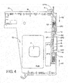
- FIG. 4 is similar to FIG. 3 , but shows the latch system L in its unlatched or unlocked configuration.
- the electronics module M comprises a one-piece or multi-piece molded polymeric or metallic (e.g. formed, cast and/or extruded aluminum or other metal) housing 10 that defines an interior space 12 that receives and retains one or more electronic components such as one or more printed circuit boards PCB comprising a microprocessor P such as an ASIC or general purpose microprocessor and/or other electronic circuitry adapted and programmed to perform a desired electronic function.
- a microprocessor P such as an ASIC or general purpose microprocessor and/or other electronic circuitry adapted and programmed to perform a desired electronic function.
- the module M It is often desirable to secure the module M to an associated support structure such as a DIN rail or other support structure in an operative position as shown in FIGS. 2 and 3 and to selectively disengage and separate the module M from the DIN rail or other support structure, and the latch system L is provided for such purposes.
- the associated support structure will be described herein as the illustrated DIN rail D, which comprises first and second longitudinally extending edges or flanges DF1,DF2 ( FIG. 2 ), but other support structures are contemplated and are within the scope of the present development.
- the housing 10 of the module M comprises or defines a recess R in a rear face MR thereof, and the recess R is dimensioned to closely receive the DIN rail D therein as shown, with the first and second DIN rail flanges DF1,DF2 located respectively adjacent first (lower) and second (upper) opposite edges R1,R2 of the recess R, with minimal clearance space between the DIN rail edges DF1,DF2 and the recess edges R1,R2.
- the recess R is open on its opposite lateral left and right sides so that the DIN rail D extends through the recess, and the recess includes in inner wall R3.
- the latch system L of the module M comprises a latch assembly LA comprising first and second latch members or latch portions LP1,LP2 that selectively engage the first and second DIN rail flanges DF1,DF2, respectively, for capturing and retaining the DIN rail flanges in the recess R for operative connection of the module M to the DIN rail D.
- first and second latch portions LP1,LP2 can be seen, along with other components of the latch assembly LA including a first spring S1 that is operatively engaged or associated with the first latch portion LP1 and a second spring S2 that is operatively engaged or associated with/between both the first and second latch portions LP1,LP2.
- the second spring S2 exerts biasing forces on the latch assembly LA that urges the first and second latch portions LP1,LP2 in opposite first and second directions XI,X2 toward their respective latched positions and, thus, urges the latch assembly LA toward its latched configuration ( FIG. 3 ).
- the first spring S1 exerts a biasing force on the first latch portion LP1, at least when the first latch portion LP1 is located in its unlatched position and the latch assembly is in its unlatched state, that urges the latch assembly LA (both the first and second latch portions LP1,LP2) in the first direction X1 when and the latch assembly LA is arranged in its unlatched configuration to maintain the latch assembly LA in its required position relative to the housing 10.
- the first and second latch portions LP1,LP2 are selectively manually movable relative to each other against the biasing forces of the second spring S2 to place the latch assembly LA in its unlatched configuration ( FIG. 4 ).
- the first and second latch portions LP1,LP2 thereof are each located in respective latched positions, and when the latch assembly is located in its unlatched position, the first and second latch portions LP1,LP2 thereof are each located in respective unlatched positions.
- the first latch portion LP1 preferably comprises a one-piece molded polymeric structure that comprises an elongated linear main portion LP1a and an inner end LP1b located adjacent the first edge R1 of the recess R.
- the inner end LP1b of the first latch portion LP1 comprises a first locking tab T1 adapted to engage and retain the first DIN rail flange DF1 in the recess R.
- the main portion LP1a of the first latch portion LP1 extends adjacent the inner wall R3 of the recess R from its inner end LP1b to an outer end LP1c that is located external to the housing 10.
- the outer end LP1c includes or defines an actuator portion or actuator tab AT adapted to be engaged by a user's thumb or finger or otherwise manually engaged by a user to move the latch assembly LA from its latched to its unlatched configuration as described below.
- the main portion LP1a of the first latch portion LP1 is exposed and at least partially defines the recess inner wall R3.
- the second latch portion LP2 also preferably comprises a one-piece molded polymeric construction that comprises a main portion LP2a and an inner end LP2b located adjacent the second edge R2 of the recess R.
- the inner end LP2b of the second latch portion LP2 comprises a second locking tab T2 adapted to engage and retain the second DIN rail flange DF2 in the recess R.
- the main portion LP2a of the second latch portion LP2 lies adjacent and preferably slidably abuts the main portion LP1a of the first latch portion LP1.
- the second latch portion LP2 further comprises a flexible, resilient tail portion LP2t connected to the main portion LP2a and that extends to an outer end LP2c located external to the housing 10 and adjacent the outer end LP1c and actuator portion/tab AT of the first lock portion LP1.
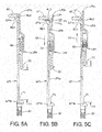
- the resilient tail portion LP2t normally lies adjacent and abuts the first lock portion LP1, but the resilient tail portion LP2t is selectively deflectable away from the first lock portion LP1 in a deflection direction XD (see FIG. 5B ) as required for the latch assembly LA to move between its latched and unlatched configurations.
- the first and second locking tabs T1,T2 are located in respective extended positions and project into the recess R beyond the first and second recess edges R1,R2, respectively, when the latch assembly LA is located in its latched configuration as shown in FIG. 3 so that the first and second DIN rail flanges DF1,DF2 are respectively captured behind the first and second locking tabs T1,T2, i.e., between the first and second locking tabs T1,T2 and the inner wall R3 of the recess R.
- the latch assembly LA is located in its unlatched configuration as shown in FIG.
- the first and second locking tabs T1,T2 are located in respective retracted positions where they are retracted relative to the first and second recess edges R1,R2, respectively, so that the first and second locking tabs are flush with or recessed relative to the first and second recess edges R1,R2 so that the first and second DIN rail flanges DF1,DF2 are able to move freely out of (or into) the recess R without being obstructed by the locking tabs T1,T2.
- the first and second locking tabs T1,T2 are thus spaced apart from each other by a first distance Y1 when the latch assembly LA is located in its latched configuration ( FIGS.
- the first spring S1 is operatively located between the inner end LP1b of the first lock portion LP1 and the housing 10. In the illustrated embodiment, the spring is maintained in a free or unloaded state when the latch assembly LA is arranged in its latched configuration or state, but it can also be partially compressed/loaded in this position of the latch assembly. In the illustrated example, the first spring S1 becomes loaded/compressed and biases the first latch portion LP1 (and also the second latch portion LP2 as described below) in the first direction X1 when the latch assembly LA is arranged in its unlatched configuration or state to ensure that the first and second latch portions LP1,LP2 are properly positioned relative to the housing 10 when the latch assembly LA is configured in its unlatched state.
- the second spring S2 is operatively located between the first and second latch portions LP1,LP2 and biases the second latch portion LP2 in a second direction X2 relative to the first latch portion toward its latched position such that the second locking tab T2 is biased toward its extended (latched) position, and the second spring S2 also biases the first latch portion LP1 in the first direction X1 relative to the second latch portion LP2.
- the second latch portion LP2 comprises a locator tab LT that projects from the tail portion LP2t
- the main portion LP1a of the first latch portion LP1 comprises first and second spaced-apart apertures, recesses or other receiving locations RL1,RL2 (see also FIG. 7 ) that are adapted to receive and retain the locator tab LT.
- the locator tab LT is located in the first receiving location RL1
- the latch assembly LA is arranged in its unlatched configuration
- the locator tab LT is located in the second receiving location RL1.
- the receiving location RL1,RL2 in which the locator tab LT is seated controls the distance (Y1,Y2) between the first and second locking tabs T1,T2.
- the locator tab LT is shaped to include a tapered outer surface LT1 oriented toward the outer end of the first latch portion LP1.
- the locator tab LT will automatically seat in the second receiving location RL2 and the resilient tail portion LP2t will resiliently return to undeflected state when the second receiving location RL2 is registered with / moves into registration with the locator tab LT as shown in FIG. 5C .
- the locator tab LT When the locator tab LT is seated in the second receiving locations RL2 as shown in FIG. 5C , the locator tab LT prevents the second spring S2 from moving the second latch portion LP2 in the second direction relative to the first latch portion LP1, but ensures that the second latch portion LP2 will move together with the first latch portion LP1 in the first direction X1 under the force of the first biasing spring S1.
- engagement between the second latch portion LP2 and the housing 10 prevents both of the first and second latch portions LP1,LP2 from moving in the first direction X1 under the biasing force of the first spring S1 beyond a desired distance, so that the latch assembly LA is restrained or maintained in its unlatched configuration and position once the locator tab LT seats in the second receiving location and the first and second latch portions LP1,LP2 move in the first direction X1 until the second latch portion LP2 abuts the housing 10.
- the first and second latch portions LP1,LP2 are allowed to move as a unit in the first direction X1 under the force f the first spring S1 until the second bite tooth T2 is moved to its retracted position relative to the second edge R2 of the recess R, but the first and second latch portions LP1,LP2 are prevented from moving in the first direction X1 beyond such retracted location of the second bite tooth T2 to ensure that the first bite tooth T1 is also located in its retracted position relative to the first edge R1 of the recess R.
- the locator tab LT When the locator tab LT is seated in the first receiving location RL1 (latch assembly LA latched), the locator tab LT prevents movement of the first and second latch portions LP1,LP2 relative to each other in respective first and second directions X1,X2 as would decrease the distance Y1, and the latch portions LP1,LP2 are properly located in their latched positions relative to the housing 10 by engagement of the first and/or second latch portions LP1,LP2 with the housing 10.
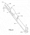
- FIGS. 8 and 9 respectively show the first and second latch portions LP1,LP2 in their latched and unlatched positions
- the second latch portion LP2 comprises at least one wing W (two wings W are shown in the illustrated embodiment) adapted to abut the module housing 10 to limit or constrain movement of the second latch portion LP2 in the second direction X2 under force of the second spring S2, and to limit movement of both the first and second latch portions LP1,LP2 in the first direction X1 when they are located in their latched and unlatched positions.
- the first latch portion LP1 includes one or more structures such as wings W2 that constrain movement of the first latch portion LP1 in the first and second directions X1,X2.
- the first and second locking tabs T1,T2 each comprise a tapered outer surface Tla,T2a ( FIG. 6 ) that diverges as it extends away from the recess inner wall R3 such that upon abutment of a DIN rail flange DF1,DF2 therewith, the first latch portion LP1 will be moved linearly in the second direction X2 relative to the housing 10 and relative to the second latch portion LP2 against the biasing force of the second spring S2, and the second latch portion LP2 will be moved linearly in the first direction X1 relative to the housing 10 and relative to the first latch portion LP1 against the biasing force of the second spring S2 so that the DIN rail D is received in the module recess R even when the latch assembly LA is arranged in its latched configuration, i.e., the module M can be mounted on the DIN rail even when the latched assembly is positioned in its latched configuration.
- the locking tabs T1,T2 are dimensioned such that the movement of the first and second latch portions LP1,LP2 relative to each other in the respective second and first directions is not of sufficient magnitude to cause the second receiving location RL2 to move into registration with the locator tab LT as would cause the first and second latch portions LP1,LP2 to become engaged with each other in the unlatched configuration.
- the latch assembly LA is moved from its latched configuration ( FIGS. 3 & 5A ) to its unlatched configuration ( FIGS. 4 & 5C ) upon a user's manual movement of the first latch portion LP1 linearly in the second direction X2 by depressing the actuator tab AT ( FIG. 5B ).
- the locator tab LT will move from the first receiving location RL1 ( FIG.
- the user manually deflects or moves the resilient tail portion LP2t of the second latch portion LP2 in the deflection direction XD until the locator tab LT exits the second receiving location RL1, at which time the second spring S2 will move the second latch portion LP2 in the second direction X2 relative to the first latch portion LP1 and/or the second spring S2 will move the first latch portion LP1 in the first direction X1 relative to the second latch portion LP2 until the locator tab LT again seats in the first receiving location RL1 so that the first and second latch portions LP1,LP2 are located in their respective latched positions as shown in FIG. 5A .
- the present development thus provides and electronics module including a latch system that allows for one-handed operation / single-point actuation, does not require a screwdriver or other tool to operate, utilizes linear movement for latching rather than pivoting or rotational movement, provides positive tactile feedback when moving between its latched and unlatched configurations, is able to be locked in an open or unlatched configuration, and that is more convenient and effective that known latch assemblies.
Landscapes
- Engineering & Computer Science (AREA)
- Microelectronics & Electronic Packaging (AREA)
- Automation & Control Theory (AREA)
- Mounting Components In General For Electric Apparatus (AREA)
- Mounting Of Printed Circuit Boards And The Like (AREA)
- Casings For Electric Apparatus (AREA)
Claims (11)
- Elektronikmodul, umfassend:ein Gehäuse (10), das eine Rückfläche beinhaltet, die eine Ausnehmung umfasst,die dafür ausgelegt ist, eine zugehörige Montageschiene aufzunehmen, wobei die Ausnehmung eine erste und eine zweite gegenüberliegende Kante umfasst;eine Verriegelungsbaugruppe (LA), die mit dem Gehäuse verbunden und dafür ausgelegt ist, selektiv und lösbar das Gehäuse an der zugehörigen Montageschiene, die in der Ausnehmung befindlich ist, zu sichern, wobei die Verriegelungsbaugruppe umfasst:einen ersten Verriegelungsabschnitt (LP1), der beweglich mit dem Gehäuse verbunden ist und einen ersten Arretierungsfortsatz (T1) umfasst, der dafür ausgelegt ist, einen ersten zugehörigen DIN-Schienenflansch (DF1) in der Ausnehmung zu ergreifen;einen zweiten Verriegelungsabschnitt (LP2), der beweglich mit dem Gehäuse benachbart zu dem ersten Verriegelungsabschnitt verbunden ist und einen zweiten Arretierungsfortsatz umfasst, der dafür ausgelegt ist, einen zweiten zugehörigen DIN-Schienenflansch (DF2) in der Ausnehmung zu ergreifen;wobei der erste und der zweite Verriegelungsabschnitt relativ zueinander zu einer verriegelten Konfiguration und einer nichtverriegelten Konfiguration sowie zwischen diesen beweglich sind, wobei
(i) in der verriegelten Konfiguration der erste und der zweite Verriegelungsabschnitt in jeweiligen verriegelten Positionen befindlich sind, in denen der erste und der zweite Arretierungsfortsatz bezugsrichtig über die erste und die zweite gegenüberliegende Kante der Ausnehmung hinweg vorstehen und die Ausnehmung teilweise blockieren; und (ii) in der nichtverriegelten Konfiguration der erste und der zweite Verriegelungsabschnitt in jeweiligen nichtverriegelten Positionen befindlich sind, in denen der erste und der zweite Arretierungsfortsatz weiter als in der verriegelten Konfiguration voneinander beabstandet sind; undeine erste und eine zweite Feder, wobei die erste Feder (S1) auf den ersten Verriegelungsabschnitt eine Vorspannkraft ausübt, die sowohl den ersten wie auch den zweiten Verriegelungsabschnitt in eine erste Richtung (X1) relativ zu dem Gehäuse drängt, wenn der erste und der zweite Verriegelungsabschnitt in der nichtverriegelten Konfiguration befindlich sind, und wobei die zweite Feder (S2) eine Vorspannkraft ausübt, die den ersten Verriegelungsabschnitt in die erste Richtung drängt und den zweiten Verriegelungsabschnitt in eine zweite Richtung (X2), die entgegengesetzt zur ersten Richtung ist, drängt, wobei die erste und die zweite Richtung hin zu den jeweiligen verriegelten Positionen des ersten und des zweiten Verriegelungsabschnittes verlaufen, wobei:der erste Verriegelungsabschnitt einen Betätigungsabschnitt umfasst, der außerhalb des Gehäuses befindlich und dafür ausgelegt ist, manuell in Eingriff genommen zu werden, um den ersten Verriegelungsabschnitt in der zweiten Richtung von seiner verriegelten Position hin zu seiner nichtverriegelten Position zu bewegen;der zweite Verriegelungsabschnitt einen elastischen Endstückabschnitt (LP2t) umfasst, der benachbart zu dem ersten Verriegelungsabschnitt liegt und der einen Lokalisationsfortsatz (LT) umfasst, der mit einem ersten Aufnahmeort (RL1) des ersten Verriegelungsabschnittes in Eingriff tritt, wenn der erste und der zweite Verriegelungsabschnitt in ihren jeweiligen verriegelten Positionen befindlich sind, wobei der Lokalisationsfortsatz dafür ausgelegt ist, eine Bewegung des ersten und des zweiten Verriegelungsabschnittes relativ zueinander in jeweiligen ersten und zweiten Richtungen zu verhindern, und der mit einem zweiten Aufnahmeort (RL2) des ersten Verriegelungsabschnittes in Eingriff tritt, wenn der erste und der zweite Verriegelungsabschnitt in ihren jeweiligen nichtverriegelten Positionen sind, wobei der Lokalisationsfortsatz dafür ausgelegt ist zu verhindern, dass die zweite Feder den zweiten Verriegelungsabschnitt in der zweiten Richtung relativ zu dem ersten Verriegelungsabschnitt bewegt, und der Lokalisationsfortsatz dafür ausgelegt ist sicherzustellen, dass sich der zweite Verriegelungsabschnitt zusammen mit dem ersten Verriegelungsabschnitt in der ersten Richtung unter der Kraft der ersten Vorspannfeder bewegt; undder zweite Verriegelungsabschnitt mit Blick auf eine Bewegung in der zweiten Richtung infolge eines Kontaktes mit dem Gehäuse eingeschränkt ist, wenn die Verriegelungsbaugruppe in dem verriegelten Zustand ist und sich der erste Verriegelungsabschnitt in der zweiten Richtung bewegt, und der erste und der zweite Verriegelungsabschnitt mit Blick auf eine Bewegung in der ersten Richtung infolge eines Kontaktes des zweiten Verriegelungsabschnittes mit dem Gehäuse eingeschränkt sind, wenn die Verriegelungsbaugruppe in dem nichtverriegelten Zustand ist. - Elektronikmodul nach Anspruch 1, wobei die zweite Feder operativ zwischen dem ersten und dem zweiten Verriegelungsabschnitt in Eingriff ist.
- Elektronikmodul nach Anspruch 1, wobei:der erste Verriegelungsabschnitt selektiv und manuell in der zweiten Richtung von seiner verriegelten Position hin zu seiner nichtverriegelten Position derart beweglich ist, dass der erste Verriegelungsabschnitt relativ zu dem zweiten Verriegelungsabschnitt gleitet, wobei das elastische Endstück in einer Umlenkrichtung in Reaktion auf einen Kontakt zwischen dem Lokalisationsfortsatz und dem ersten Verriegelungsabschnitt umgelenkt wird und sich der Lokalisationsfortsatz von dem ersten Aufnahmeort zu dem zweiten Aufnahmeort bewegt, wenn sich der Lokalisationsfortsatz in Registrierung mit dem zweiten Aufnahmeort bewegt;der Eingriff des Lokalisationsfortsatzes mit dem zweiten Aufnahmeort den zweiten Verriegelungsabschnitt mit dem ersten Verriegelungsabschnitt für eine Bewegung in der ersten Richtung unter der Kraft der ersten Feder koppelt, sodass sich der zweite Verriegelungsabschnitt mit dem ersten Verriegelungsabschnitt in der ersten Richtung in seine nichtverriegelte Position bewegt, wenn die erste Feder den ersten Verriegelungsabschnitt in der ersten Richtung bewegt; undder Eingriff des zweiten Verriegelungsabschnittes mit dem Gehäuse die Bewegung des ersten und des zweiten Verriegelungsabschnittes in der ersten Richtung begrenzt, wenn der Lokalisationsfortsatz an dem zweiten Aufnahmeort befindlich ist.
- Elektronikmodul nach Anspruch 3, wobei das elastische Endstück selektiv und manuell umlenkbar ist, um den Lokalisationsfortsatz von dem zweiten Aufnahmeort wegzuziehen, wenn der erste und der zweite Verriegelungsabschnitt in der verriegelten Konfiguration befindlich sind, wobei die zweite Feder den ersten Verriegelungsabschnitt in der ersten Richtung in die verriegelten Position des ersten Verriegelungsabschnittes bewegt, wenn der Lokalisationsfortsatz von dem zweiten Aufnahmeort weggezogen wird.
- Elektronikmodul nach Anspruch 4, wobei der erste und der zweite Verriegelungsabschnitt relativ zueinander gegen die zweite Vorspannkraft der zweiten Feder in der zweiten und der ersten Richtung bezugsrichtig hin zu ihren nichtverriegelten Positionen beweglich sind, um zu ermöglichen, dass sich die zugehörige Montageschiene in die Ausnehmung bewegt, wenn der erste und der zweite Verriegelungsabschnitt in ihrer verriegelten Konfiguration angeordnet sind.
- Elektronikmodul nach Anspruch 5, wobei der Lokalisationsfortsatz eine verjüngte äußere Oberfläche umfasst, die hin zu dem Betätigungsabschnitt des ersten Verriegelungsabschnittes orientiert ist und sich vom dem Betätigungsabschnitt weg erstreckt, wenn sie sich von dem zweiten Verriegelungsabschnitt weg erstreckt, wobei die verjüngte äußere Oberfläche den ersten Verriegelungsabschnitt bei einer Bewegung des ersten Verriegelungsabschnittes relativ zu dem zweiten Verriegelungsabschnitt in der zweiten Richtung kontaktiert, sodass der elastische Endstückabschnitt in der Umlenkrichtung umgelenkt wird und der Lokalisationsfortsatz wenigstens teilweise von dem ersten Aufnahmeort weggezogen wird.
- Elektronikmodul, umfassend:ein Gehäuse (10), das eine Rückfläche beinhaltet, die eine Ausnehmung umfasst, wobei die Ausnehmung eine erste und eine zweite gegenüberliegende Kante und einen inneren Bereich umfasst;eine Verriegelungsbaugruppe (LA), die mit dem Gehäuse verbunden und dafür ausgelegt ist, selektiv und lösbar das Gehäuse an einer zugehörigen Montageschiene, die in der Ausnehmung befindlich ist, zu sichern, wobei die Verriegelungsbaugruppe umfasst:einen ersten Verriegelungsabschnitt (LP1), der beweglich mit dem Gehäuse verbunden ist und einen ersten Arretierungsfortsatz (T1) umfasst, der dafür ausgelegt ist, einen ersten Flansch (DF1) der zugehörigen Montageschiene in der Ausnehmung zu ergreifen;einen zweiten Verriegelungsabschnitt (LP2), der beweglich mit dem Gehäuse verbunden ist und gleitverschieblich an dem ersten Verriegelungsabschnitt anliegt, wobei der zweite Verriegelungsabschnitt einen zweiten Arretierungsfortsatz umfasst, der dafür ausgelegt ist, einen zweiten Flansch (DF2) der zugehörigen Montageschiene in der Ausnehmung zu ergreifen;wobei der erste und der zweite Verriegelungsabschnitt relativ zueinander zu einer verriegelten Konfiguration und einer nichtverriegelten Konfiguration sowie zwischen diesen beweglich sind, wobei
(i) in der verriegelten Konfiguration der Verriegelungsbaugruppe der erste und der zweite Verriegelungsabschnitt in jeweiligen verriegelten Positionen befindlich sind und der erste und der zweite Arretierungsfortsatz um einen ersten Abstand Y1 voneinander beabstandet sind und bezugsrichtig über die erste und die zweite gegenüberliegende Kanten der Ausnehmung hinweg vorstehen und die Ausnehmung teilweise blockieren; und (ii) in der nichtverriegelten Konfiguration der Verriegelungsbaugruppe der erste und der zweite Verriegelungsabschnitt in jeweiligen nichtverriegelten Positionen befindlich sind und der erste und der zweite Arretierungsfortsatz um einen zweiten Abstand Y2 voneinander beabstandet sind, wobei Y2 > Y1 gilt;eine erste und eine zweite Feder, wobei die erste Feder (S1) operativ zwischen dem Gehäuse und der Verriegelungsbaugruppe befindlich ist und den ersten Verriegelungsabschnitt in einer ersten Richtung vorspannt, wenn die Verriegelungsbaugruppe in der nichtverriegelten Konfiguration angeordnet ist, und wobei die zweite Feder (S2) operativ zwischen dem ersten und dem zweiten Verriegelungsabschnitt befindlich ist und den ersten Verriegelungsabschnitt in der ersten Richtung (X1) vorspannt und den zweiten Verriegelungsabschnitt in einer zweiten Richtung (X2) entgegengesetzt zur ersten Richtung vorspannt, wobei die ersten und zweiten Richtungen hin zu den jeweiligen verriegelten Positionen des ersten und des zweiten Verriegelungsabschnittes verlaufen; wobeider erste Verriegelungsabschnitt einen Betätigungsabschnitt (AT) umfasst, der nach außen von dem Gehäuse vorsteht und dafür ausgelegt ist, manuell in Eingriff genommen und linear bewegt zu werden, um den ersten Verriegelungsabschnitt von seiner verriegelten Position hin zu seiner nichtverriegelten Position zu bewegen,der zweite Verriegelungsabschnitt einen elastischen Endstückabschnitt (LP2t) umfasst, der benachbart zu dem ersten Verriegelungsabschnitt liegt und der einen Lokalisationsfortsatz (LT) umfasst, der einen ersten Aufnahmeort (RL1) des ersten Verriegelungsabschnittes in Eingriff nimmt, wenn der erste und der zweite Verriegelungsabschnitt in ihren jeweiligen verriegelten Positionen befindlich sind, wobei der Lokalisationsfortsatz dafür ausgelegt ist, eine Bewegung des ersten und des zweiten Verriegelungsabschnittes relativ zueinander in jeweiligen ersten und zweiten Richtungen zu verhindern, und der einen zweiten Aufnahmeort (RL2) des ersten Verriegelungsabschnittes in Eingriff nimmt, wenn der erste und der zweite Verriegelungsabschnitt in ihren jeweiligen nichtverriegelten Positionen befindlich sind, wobei der Lokalisationsfortsatz dafür ausgelegt ist zu verhindern, dass die zweite Feder den zweiten Verriegelungsabschnitt in der zweiten Richtung relativ zu dem ersten Verriegelungsabschnitt bewegt, und der Lokalisationsfortsatz dafür ausgelegt ist sicherzustellen, dass sich der zweite Verriegelungsabschnitt zusammen mit dem ersten Verriegelungsabschnitt in der ersten Richtung unter der Kraft der ersten Vorspannfeder bewegt; undder zweite Verriegelungsabschnitt mit Blick auf eine Bewegung in der zweiten Richtung infolge eines Kontaktes mit dem Gehäuse einschränkt ist, wenn die Verriegelungsbaugruppe in dem verriegelten Zustand ist und sich der erste Verriegelungsabschnitt in der zweiten Richtung bewegt, und der erste und der zweite Verriegelungsabschnitt mit Blick auf eine Bewegung in der ersten Richtung infolge eines Kontaktes des zweiten Verriegelungsabschnittes mit dem Gehäuse eingeschränkt sind, wenn die Verriegelungsbaugruppe in dem nichtverriegelten Zustand ist. - Elektronikmodul nach Anspruch 7, wobei der zweite Verriegelungsabschnitt mit Blick auf eine Bewegung zusammen mit dem ersten Verriegelungsabschnitt in der zweiten Richtung eingeschränkt ist, wenn der Betätigungsabschnitt linear in der zweiten Richtung bewegt wird, um den ersten Verriegelungsabschnitt von seiner verriegelten Position hin zu seiner nichtverriegelten Position zu bewegen, und wobei der elastische Endstückabschnitt des zweiten Verriegelungsabschnittes weg von dem ersten Verriegelungsabschnitt in einer Umlenkrichtung umgelenkt wird, um zu ermöglichen, dass der Lokalisationsfortsatz den ersten Aufnahmeort verlässt, um eine lineare Bewegung des ersten Verriegelungsabschnittes relativ zu dem zweiten Verriegelungsabschnitt zu ermöglichen, wenn der Betätigungsabschnitt linear in der zweiten Richtung bewegt wird, um den ersten Verriegelungsabschnitt von seiner verriegelten Position hin zu seiner nichtverriegelten Position zu bewegen.
- Elektronikmodul nach Anspruch 8, wobei:sich der Lokalisationsfortsatz des zweiten Verriegelungsabschnittes von dem ersten Aufnahmeort zu dem zweiten Aufnahmeort bewegt, wenn der Betätigungsabschnitt in Eingriff genommen wird, um den ersten Verriegelungsabschnitt in der zweiten Richtung relativ zu dem zweiten Verriegelungsabschnitt zu bewegen; undder Eingriff des Lokalisationsfortsatzes mit dem zweiten Aufnahmeort den zweiten Verriegelungsabschnitt mit dem ersten Verriegelungsabschnitt für eine Bewegung mit dem ersten Verriegelungsabschnitt in der ersten Richtung koppelt, wenn der Betätigerabschnitt gelöst wird und die erste Feder den ersten Verriegelungsabschnitt in der ersten Richtung in seine nichtverriegelte Position bewegt.
- Elektronikmodul nach Anspruch 9, wobei der Eingriff des zweiten Verriegelungsabschnittes mit dem Gehäuse die Bewegung des ersten und des zweiten Verriegelungsabschnittes in der ersten Richtung unter der Kraft der ersten Feder begrenzt, wenn der Lokalisationsfortsatz an dem zweiten Aufnahmeort befindlich ist, sodass die Verriegelungsbaugruppe in der nichtverriegelten Konfiguration befindlich ist; und
wobei das elastische Endstück ein äußeres Ende umfasst, das außerhalb des Gehäuses befindlich ist, wobei das elastische Endstück selektiv und manuell in der Umlenkrichtung beweglich ist, wenn die Verriegelungsbaugruppe in der nichtverriegelten Konfiguration angeordnet ist, um den Lokalisationsfortsatz weg von dem zweiten Aufnahmeort zu bewegen, sodass die zweite Feder den ersten Verriegelungsabschnitt in der ersten Richtung relativ zu dem zweiten Verriegelungsabschnitt zu der verriegelten Position des ersten Verriegelungsabschnittes bewegt. - Elektronikmodul nach Anspruch 10, wobei der Lokalisationsfortsatz eine verjüngte äußere Oberfläche umfasst, die hin zu dem Betätigungsabschnitt des ersten Verriegelungsabschnittes orientiert ist und die sich von dem Betätigungsabschnitt weg erstreckt, wenn sie sich von dem zweiten Verriegelungsabschnitt weg erstreckt, wobei die verjüngte äußere Oberfläche von dem ersten Verriegelungsabschnitt bei einer Bewegung des ersten Verriegelungsabschnittes relativ zu dem zweiten Verriegelungsabschnitt in der zweiten Richtung in Eingriff genommen wird, sodass der elastische Endstückabschnitt in der Umlenkrichtung umgelenkt wird; und
wobei der erste und der zweite Arretierungsfortsatz jeweilige verjüngte Oberflächen umfassen, die auseinanderlaufen, wenn sie sich von dem inneren Bereich der Ausnehmung weg erstrecken, sodass der erste und der zweite Verriegelungsabschnitt bezugsrichtig in den zweiten und ersten Richtungen bewegt werden, wenn der erste und der zweite Arretierungsfortsatz von dem ersten und dem zweiten Flansch der zugehörigen Montageschiene beim Einführen der zugehörigen Montageschiene in die Ausnehmung kontaktiert werden, wenn die Verriegelungsbaugruppe in ihrer verriegelten Konfiguration angeordnet ist.
Applications Claiming Priority (1)
| Application Number | Priority Date | Filing Date | Title |
|---|---|---|---|
| US14/640,537 US9485879B2 (en) | 2015-03-06 | 2015-03-06 | Single action DIN rail latch |
Publications (2)
| Publication Number | Publication Date |
|---|---|
| EP3065520A1 EP3065520A1 (de) | 2016-09-07 |
| EP3065520B1 true EP3065520B1 (de) | 2021-12-01 |
Family
ID=55699340
Family Applications (1)
| Application Number | Title | Priority Date | Filing Date |
|---|---|---|---|
| EP16158875.1A Active EP3065520B1 (de) | 2015-03-06 | 2016-03-07 | Din-schienenverriegelung mit einfachaktion |
Country Status (3)
| Country | Link |
|---|---|
| US (2) | US9485879B2 (de) |
| EP (1) | EP3065520B1 (de) |
| CN (1) | CN105939589B (de) |
Cited By (1)
| Publication number | Priority date | Publication date | Assignee | Title |
|---|---|---|---|---|
| RU238572U1 (ru) * | 2025-04-08 | 2025-10-31 | Сергей Владимирович Геронов | Распределительный блок |
Families Citing this family (25)
| Publication number | Priority date | Publication date | Assignee | Title |
|---|---|---|---|---|
| AT509160B1 (de) * | 2009-12-10 | 2012-05-15 | Siemens Ag | Einhänge- und rastmechanismus für normschienen |
| JP6526633B2 (ja) * | 2013-09-26 | 2019-06-05 | エービービー シュヴァイツ アクチェンゲゼルシャフト | レールに取り付けられる制御システム |
| DE102015218108B4 (de) * | 2015-09-21 | 2017-06-01 | Ellenberger & Poensgen Gmbh | Schaltgerät |
| DE202015106673U1 (de) * | 2015-12-08 | 2016-01-14 | H & B Electronic Gmbh & Co. Kg | Anreihbares Bauelement |
| EP3200292B1 (de) * | 2016-01-29 | 2018-08-22 | Siemens Aktiengesellschaft | Vorrichtung zur befestigung eines kommunikations- und/oder automatisierungsgeräts an einer hutschiene und kommunikations- und/oder automatisierungsgerät |
| DE102016203700A1 (de) * | 2016-03-07 | 2017-09-07 | Te Connectivity Germany Gmbh | Schienenbefestigungssystem mit Systemkopplung |
| US10143104B2 (en) * | 2016-09-30 | 2018-11-27 | Siemens Industry, Inc. | Adaptive mounting rail and mounting assemblies for electronic devices |
| TWM541651U (zh) * | 2016-10-21 | 2017-05-11 | 啓碁科技股份有限公司 | 懸吊式固定座 |
| US10109934B2 (en) * | 2016-12-20 | 2018-10-23 | Schneider Electric USA, Inc. | DIN rail latching means |
| EP3376617B1 (de) * | 2017-03-14 | 2019-01-09 | Sick AG | Befestigungsvorrichtung |
| TWI640139B (zh) * | 2017-05-26 | 2018-11-01 | 四零四科技股份有限公司 | 工業用輸入輸出裝置的夾持機構 |
| USD908087S1 (en) | 2017-11-11 | 2021-01-19 | Rockwall Automation Asia Pacific Business Ctr. Pte. Ltd. | Connector |
| US10631426B1 (en) | 2018-09-28 | 2020-04-21 | Rockwell Automation Technologies, Inc. | Electronics module mounting system |
| US10734093B1 (en) * | 2019-01-31 | 2020-08-04 | Hewlett Packard Enterprise Development Lp | Chassis mounting for computing devices |
| US10716235B1 (en) * | 2019-02-01 | 2020-07-14 | Cisco Technology, Inc. | Adjustable mounting rail latches |
| KR102098755B1 (ko) * | 2019-12-26 | 2020-04-08 | 제일전기공업 주식회사 | 고정봉형 결합장치가 구비된 차단기 |
| US11418014B2 (en) * | 2020-05-30 | 2022-08-16 | Regal Beloit America, Inc. | Retractable DIN clip |
| US11828481B2 (en) * | 2020-10-16 | 2023-11-28 | Honeywell International, Inc. | Building controller with adaptable mount |
| CN112616287A (zh) * | 2020-12-28 | 2021-04-06 | 中国人民解放军陆军炮兵防空兵学院 | 一种频谱通信控制器 |
| US11758661B2 (en) | 2021-02-19 | 2023-09-12 | Rockwell Automation Technologies, Inc. | Locking input/output module |
| US12035492B2 (en) | 2021-08-06 | 2024-07-09 | International Business Machines Corporation | Preloaded flexible latch assembly |
| US12107377B2 (en) | 2021-09-14 | 2024-10-01 | Appleton Grp Llc | Plastic latching system for securement of electronic component to a DIN rail |
| US20230102957A1 (en) * | 2021-09-27 | 2023-03-30 | James David FISHER | Din rail mounting adapter |
| JP2023152025A (ja) * | 2022-04-01 | 2023-10-16 | オムロン株式会社 | 機器取付構造 |
| US12513843B2 (en) * | 2024-04-24 | 2025-12-30 | Schneider Electric Buildings Americas, Inc. | DIN rail and wall mounted enclosure assembly and method of use |
Family Cites Families (35)
| Publication number | Priority date | Publication date | Assignee | Title |
|---|---|---|---|---|
| FR2657200B1 (fr) | 1990-01-12 | 1992-05-15 | Hager Electro | Dispositif de clipsage pour appareils electriques modulaires a juxtaposer et appareil modulaire muni d'un tel dispositif. |
| CH683047A5 (de) * | 1992-02-18 | 1993-12-31 | Woertz Ag | Schutzleiterklemme. |
| DE59301211D1 (de) * | 1992-12-17 | 1996-02-01 | Ellenberger & Poensgen | An einer Tragschiene befestigbares Installationsgerät |
| DE29806691U1 (de) * | 1998-04-15 | 1998-05-28 | Weidmüller Interface GmbH & Co, 32760 Detmold | Montagefuß für anreihbare Einbaugehäuse oder Klemmen |
| US5904592A (en) | 1998-09-29 | 1999-05-18 | Allen-Bradley Company, Llc | Dual mode din rail latch with tactile feedback |
| US6172875B1 (en) | 1998-11-17 | 2001-01-09 | Rockwell Technologies, Llc | Programmable logic controller module assembly and locking system |
| FR2791187B1 (fr) * | 1999-03-15 | 2001-05-04 | Schneider Electric Sa | Appareil electrique a encliqueter sur un rail |
| US6454614B1 (en) * | 1999-09-16 | 2002-09-24 | Entrelec S.A. | Electrical connection device comprising a catch for fastening to a support rail |
| US6425770B1 (en) * | 2000-04-14 | 2002-07-30 | Rockwell Automation Technologies, Inc. | Input/output device having removable module |
| ATE331317T1 (de) * | 2000-09-25 | 2006-07-15 | Weidmueller Interface | Reihenklemme mit schneidkontakten und kontaktbetätigungsstücken |
| US6431909B1 (en) | 2000-09-28 | 2002-08-13 | Rockwell Automation Technologies, Inc. | DIN rail attachment method and apparatus |
| DE10227422B4 (de) * | 2002-06-20 | 2018-11-22 | Werner Turck Gmbh & Co. Kg | Datenumwandler |
| US7059898B2 (en) | 2004-10-13 | 2006-06-13 | Rockwell Automation Technologies, Inc. | DIN rail latching system and method |
| WO2006069634A1 (de) * | 2004-12-24 | 2006-07-06 | Abb Patent Gmbh | Schnellbefestigung an einem elektrischen installationsgerät |
| TWI308859B (en) * | 2006-11-03 | 2009-04-11 | Delta Electronics Thailand Public Co Ltd | A detachable electronic device and a latching structure thereof |
| US7758368B2 (en) * | 2007-05-29 | 2010-07-20 | Honeywell International Inc. | DIN rail mount |
| US8001419B2 (en) | 2007-11-13 | 2011-08-16 | Rockwell Automation Technologies, Inc. | Energy storage module |
| US7952859B2 (en) * | 2009-04-03 | 2011-05-31 | Etherwan Systems, Inc. | Fixing device for industrial communication product |
| US7980891B2 (en) | 2009-05-05 | 2011-07-19 | Rockwell Automation Technologies, Inc. | Integrated DIN rail attachment feature for optimized constraint |
| US8066239B2 (en) | 2009-06-15 | 2011-11-29 | Rockwell Automation Technologies, Inc. | Integrated DIN rail attachment feature for superior attachment |
| US8011951B2 (en) * | 2009-06-23 | 2011-09-06 | General Electric Company | Rail mounting apparatus |
| JP5104827B2 (ja) * | 2009-08-20 | 2012-12-19 | 富士電機機器制御株式会社 | 電気機器のレール取付け構造 |
| DE102009050367A1 (de) * | 2009-10-22 | 2011-04-28 | Phoenix Contact Gmbh & Co. Kg | Federkraftanschlussklemme |
| US8441798B2 (en) * | 2010-04-26 | 2013-05-14 | Cooper Technologies Company | Mounting adapter for mounting electronic device on support rail |
| DE102010023423A1 (de) * | 2010-06-11 | 2011-12-15 | Wago Verwaltungsgesellschaft Mbh | Federklemmelement und Reihenklemme |
| DE202010008319U1 (de) * | 2010-08-20 | 2011-11-21 | Weidmüller Interface GmbH & Co. KG | Tragschienen- und Modulverrastung |
| JP4844911B1 (ja) * | 2011-02-17 | 2011-12-28 | 株式会社安川電機 | Dinレール取付型機器 |
| US8226433B1 (en) * | 2011-03-23 | 2012-07-24 | Phoenix Contact Development & Manufacturing, Inc. | Latch assembly for mounting power supply base for a process fieldbus on a DIN rail and method |
| DE102011076550B4 (de) * | 2011-05-26 | 2015-09-24 | Wöhner GmbH & Co. KG Elektrotechnische Systeme | Schaltvorrichtung |
| EP2551973B1 (de) * | 2011-07-28 | 2016-03-23 | ABB Technology AG | Klemmelement |
| AU2012301205B2 (en) * | 2011-08-30 | 2017-04-20 | Te Connectivity India Private Limited | Electrical component for rail mounting |
| JP6003506B2 (ja) | 2011-10-13 | 2016-10-05 | オムロン株式会社 | 電気機器の筐体 |
| US9209608B2 (en) * | 2011-11-23 | 2015-12-08 | Emerson Electric Company | Clamping device having a pair of screws actuating a pair of hooks to clamp a DIN rail to a base module |
| CN103260376B (zh) * | 2012-02-16 | 2017-03-22 | 富泰华工业(深圳)有限公司 | 止动件及具有该止动件的电器元件安装固定装置 |
| US9136648B2 (en) | 2012-07-12 | 2015-09-15 | Rockwell Automation Technologies, Inc. | Din or panel ground integral to connector body |
-
2015
- 2015-03-06 US US14/640,537 patent/US9485879B2/en active Active
-
2016
- 2016-03-07 EP EP16158875.1A patent/EP3065520B1/de active Active
- 2016-03-07 CN CN201610127662.4A patent/CN105939589B/zh active Active
- 2016-10-27 US US15/336,227 patent/US9967995B2/en active Active
Non-Patent Citations (1)
| Title |
|---|
| None * |
Cited By (1)
| Publication number | Priority date | Publication date | Assignee | Title |
|---|---|---|---|---|
| RU238572U1 (ru) * | 2025-04-08 | 2025-10-31 | Сергей Владимирович Геронов | Распределительный блок |
Also Published As
| Publication number | Publication date |
|---|---|
| US9485879B2 (en) | 2016-11-01 |
| US20170049001A1 (en) | 2017-02-16 |
| CN105939589A (zh) | 2016-09-14 |
| CN105939589B (zh) | 2018-10-26 |
| EP3065520A1 (de) | 2016-09-07 |
| US9967995B2 (en) | 2018-05-08 |
| US20160262274A1 (en) | 2016-09-08 |
Similar Documents
| Publication | Publication Date | Title |
|---|---|---|
| EP3065520B1 (de) | Din-schienenverriegelung mit einfachaktion | |
| US10411372B2 (en) | DIN latch mechanism | |
| CN102714373B (zh) | 具有锁紧机构的插头元件 | |
| EP2772993B1 (de) | Verbinderanordnung mit Verbinderpositionsbestätigungsstabilisator | |
| US10420232B2 (en) | DIN rail device mount assemblies, systems and methods including locking mechanisms | |
| US10483663B2 (en) | Terminal block with retention features for a removable I/O module | |
| JP4576507B2 (ja) | Dinレール・ラッチ・システム及び方法 | |
| US9728896B2 (en) | Lever-type electrical connector with connector positioning assurance member | |
| US10553995B2 (en) | Snap-lock relay socket | |
| US20140054061A1 (en) | Multi-drive common control bus connector system | |
| CN107104366A (zh) | 用于轨道安装的电气设备 | |
| US20200259939A1 (en) | Locking mechanism of a mobile terminal battery cover | |
| EP3708031A1 (de) | Anschlussvorrichtung | |
| US7918678B2 (en) | Connector assemblies having guide rails with latch assemblies | |
| JP2019511833A (ja) | 電子機器筐体を担持するためのキャリアアセンブリ | |
| CN102939430A (zh) | 用于门致动器的安装布置结构 | |
| JP2015115325A (ja) | 電気的センタアッセンブリによって作動されるレバー | |
| CN100566058C (zh) | 锁紧装置 | |
| EP2111674B1 (de) | Verbindersystem für eingeschränktes umfeld | |
| US9548575B2 (en) | Device for fixing and electrical contacting a facing element of an aircraft on a support structure | |
| JP5530866B2 (ja) | 電気機器の支持レール用取付け装置 | |
| US10779425B2 (en) | Electrical apparatus comprising a locking device for an attachment rail | |
| US10135188B2 (en) | Enclosure assembly for an electrical connector and same | |
| US12497809B2 (en) | Pre-mounted lock for a door of a low voltage enclosure | |
| JP3900531B2 (ja) | レール取付装置 |
Legal Events
| Date | Code | Title | Description |
|---|---|---|---|
| PUAI | Public reference made under article 153(3) epc to a published international application that has entered the european phase |
Free format text: ORIGINAL CODE: 0009012 |
|
| AK | Designated contracting states |
Kind code of ref document: A1 Designated state(s): AL AT BE BG CH CY CZ DE DK EE ES FI FR GB GR HR HU IE IS IT LI LT LU LV MC MK MT NL NO PL PT RO RS SE SI SK SM TR |
|
| AX | Request for extension of the european patent |
Extension state: BA ME |
|
| STAA | Information on the status of an ep patent application or granted ep patent |
Free format text: STATUS: REQUEST FOR EXAMINATION WAS MADE |
|
| 17P | Request for examination filed |
Effective date: 20170217 |
|
| RBV | Designated contracting states (corrected) |
Designated state(s): AL AT BE BG CH CY CZ DE DK EE ES FI FR GB GR HR HU IE IS IT LI LT LU LV MC MK MT NL NO PL PT RO RS SE SI SK SM TR |
|
| STAA | Information on the status of an ep patent application or granted ep patent |
Free format text: STATUS: EXAMINATION IS IN PROGRESS |
|
| 17Q | First examination report despatched |
Effective date: 20190709 |
|
| GRAP | Despatch of communication of intention to grant a patent |
Free format text: ORIGINAL CODE: EPIDOSNIGR1 |
|
| STAA | Information on the status of an ep patent application or granted ep patent |
Free format text: STATUS: GRANT OF PATENT IS INTENDED |
|
| INTG | Intention to grant announced |
Effective date: 20210622 |
|
| GRAS | Grant fee paid |
Free format text: ORIGINAL CODE: EPIDOSNIGR3 |
|
| GRAA | (expected) grant |
Free format text: ORIGINAL CODE: 0009210 |
|
| STAA | Information on the status of an ep patent application or granted ep patent |
Free format text: STATUS: THE PATENT HAS BEEN GRANTED |
|
| AK | Designated contracting states |
Kind code of ref document: B1 Designated state(s): AL AT BE BG CH CY CZ DE DK EE ES FI FR GB GR HR HU IE IS IT LI LT LU LV MC MK MT NL NO PL PT RO RS SE SI SK SM TR |
|
| REG | Reference to a national code |
Ref country code: GB Ref legal event code: FG4D |
|
| REG | Reference to a national code |
Ref country code: AT Ref legal event code: REF Ref document number: 1453011 Country of ref document: AT Kind code of ref document: T Effective date: 20211215 Ref country code: CH Ref legal event code: EP |
|
| REG | Reference to a national code |
Ref country code: IE Ref legal event code: FG4D |
|
| REG | Reference to a national code |
Ref country code: DE Ref legal event code: R096 Ref document number: 602016066731 Country of ref document: DE |
|
| REG | Reference to a national code |
Ref country code: LT Ref legal event code: MG9D |
|
| REG | Reference to a national code |
Ref country code: NL Ref legal event code: MP Effective date: 20211201 |
|
| REG | Reference to a national code |
Ref country code: AT Ref legal event code: MK05 Ref document number: 1453011 Country of ref document: AT Kind code of ref document: T Effective date: 20211201 |
|
| PG25 | Lapsed in a contracting state [announced via postgrant information from national office to epo] |
Ref country code: RS Free format text: LAPSE BECAUSE OF FAILURE TO SUBMIT A TRANSLATION OF THE DESCRIPTION OR TO PAY THE FEE WITHIN THE PRESCRIBED TIME-LIMIT Effective date: 20211201 Ref country code: LT Free format text: LAPSE BECAUSE OF FAILURE TO SUBMIT A TRANSLATION OF THE DESCRIPTION OR TO PAY THE FEE WITHIN THE PRESCRIBED TIME-LIMIT Effective date: 20211201 Ref country code: FI Free format text: LAPSE BECAUSE OF FAILURE TO SUBMIT A TRANSLATION OF THE DESCRIPTION OR TO PAY THE FEE WITHIN THE PRESCRIBED TIME-LIMIT Effective date: 20211201 Ref country code: BG Free format text: LAPSE BECAUSE OF FAILURE TO SUBMIT A TRANSLATION OF THE DESCRIPTION OR TO PAY THE FEE WITHIN THE PRESCRIBED TIME-LIMIT Effective date: 20220301 Ref country code: AT Free format text: LAPSE BECAUSE OF FAILURE TO SUBMIT A TRANSLATION OF THE DESCRIPTION OR TO PAY THE FEE WITHIN THE PRESCRIBED TIME-LIMIT Effective date: 20211201 |
|
| PG25 | Lapsed in a contracting state [announced via postgrant information from national office to epo] |
Ref country code: SE Free format text: LAPSE BECAUSE OF FAILURE TO SUBMIT A TRANSLATION OF THE DESCRIPTION OR TO PAY THE FEE WITHIN THE PRESCRIBED TIME-LIMIT Effective date: 20211201 Ref country code: PL Free format text: LAPSE BECAUSE OF FAILURE TO SUBMIT A TRANSLATION OF THE DESCRIPTION OR TO PAY THE FEE WITHIN THE PRESCRIBED TIME-LIMIT Effective date: 20211201 Ref country code: NO Free format text: LAPSE BECAUSE OF FAILURE TO SUBMIT A TRANSLATION OF THE DESCRIPTION OR TO PAY THE FEE WITHIN THE PRESCRIBED TIME-LIMIT Effective date: 20220301 Ref country code: LV Free format text: LAPSE BECAUSE OF FAILURE TO SUBMIT A TRANSLATION OF THE DESCRIPTION OR TO PAY THE FEE WITHIN THE PRESCRIBED TIME-LIMIT Effective date: 20211201 Ref country code: HR Free format text: LAPSE BECAUSE OF FAILURE TO SUBMIT A TRANSLATION OF THE DESCRIPTION OR TO PAY THE FEE WITHIN THE PRESCRIBED TIME-LIMIT Effective date: 20211201 Ref country code: GR Free format text: LAPSE BECAUSE OF FAILURE TO SUBMIT A TRANSLATION OF THE DESCRIPTION OR TO PAY THE FEE WITHIN THE PRESCRIBED TIME-LIMIT Effective date: 20220302 Ref country code: ES Free format text: LAPSE BECAUSE OF FAILURE TO SUBMIT A TRANSLATION OF THE DESCRIPTION OR TO PAY THE FEE WITHIN THE PRESCRIBED TIME-LIMIT Effective date: 20211201 |
|
| PG25 | Lapsed in a contracting state [announced via postgrant information from national office to epo] |
Ref country code: NL Free format text: LAPSE BECAUSE OF FAILURE TO SUBMIT A TRANSLATION OF THE DESCRIPTION OR TO PAY THE FEE WITHIN THE PRESCRIBED TIME-LIMIT Effective date: 20211201 |
|
| PG25 | Lapsed in a contracting state [announced via postgrant information from national office to epo] |
Ref country code: SM Free format text: LAPSE BECAUSE OF FAILURE TO SUBMIT A TRANSLATION OF THE DESCRIPTION OR TO PAY THE FEE WITHIN THE PRESCRIBED TIME-LIMIT Effective date: 20211201 Ref country code: SK Free format text: LAPSE BECAUSE OF FAILURE TO SUBMIT A TRANSLATION OF THE DESCRIPTION OR TO PAY THE FEE WITHIN THE PRESCRIBED TIME-LIMIT Effective date: 20211201 Ref country code: RO Free format text: LAPSE BECAUSE OF FAILURE TO SUBMIT A TRANSLATION OF THE DESCRIPTION OR TO PAY THE FEE WITHIN THE PRESCRIBED TIME-LIMIT Effective date: 20211201 Ref country code: PT Free format text: LAPSE BECAUSE OF FAILURE TO SUBMIT A TRANSLATION OF THE DESCRIPTION OR TO PAY THE FEE WITHIN THE PRESCRIBED TIME-LIMIT Effective date: 20220401 Ref country code: EE Free format text: LAPSE BECAUSE OF FAILURE TO SUBMIT A TRANSLATION OF THE DESCRIPTION OR TO PAY THE FEE WITHIN THE PRESCRIBED TIME-LIMIT Effective date: 20211201 Ref country code: CZ Free format text: LAPSE BECAUSE OF FAILURE TO SUBMIT A TRANSLATION OF THE DESCRIPTION OR TO PAY THE FEE WITHIN THE PRESCRIBED TIME-LIMIT Effective date: 20211201 |
|
| REG | Reference to a national code |
Ref country code: DE Ref legal event code: R097 Ref document number: 602016066731 Country of ref document: DE |
|
| PG25 | Lapsed in a contracting state [announced via postgrant information from national office to epo] |
Ref country code: IS Free format text: LAPSE BECAUSE OF FAILURE TO SUBMIT A TRANSLATION OF THE DESCRIPTION OR TO PAY THE FEE WITHIN THE PRESCRIBED TIME-LIMIT Effective date: 20220401 |
|
| PLBE | No opposition filed within time limit |
Free format text: ORIGINAL CODE: 0009261 |
|
| STAA | Information on the status of an ep patent application or granted ep patent |
Free format text: STATUS: NO OPPOSITION FILED WITHIN TIME LIMIT |
|
| PG25 | Lapsed in a contracting state [announced via postgrant information from national office to epo] |
Ref country code: MC Free format text: LAPSE BECAUSE OF FAILURE TO SUBMIT A TRANSLATION OF THE DESCRIPTION OR TO PAY THE FEE WITHIN THE PRESCRIBED TIME-LIMIT Effective date: 20211201 Ref country code: DK Free format text: LAPSE BECAUSE OF FAILURE TO SUBMIT A TRANSLATION OF THE DESCRIPTION OR TO PAY THE FEE WITHIN THE PRESCRIBED TIME-LIMIT Effective date: 20211201 Ref country code: AL Free format text: LAPSE BECAUSE OF FAILURE TO SUBMIT A TRANSLATION OF THE DESCRIPTION OR TO PAY THE FEE WITHIN THE PRESCRIBED TIME-LIMIT Effective date: 20211201 |
|
| REG | Reference to a national code |
Ref country code: CH Ref legal event code: PL |
|
| 26N | No opposition filed |
Effective date: 20220902 |
|
| PG25 | Lapsed in a contracting state [announced via postgrant information from national office to epo] |
Ref country code: SI Free format text: LAPSE BECAUSE OF FAILURE TO SUBMIT A TRANSLATION OF THE DESCRIPTION OR TO PAY THE FEE WITHIN THE PRESCRIBED TIME-LIMIT Effective date: 20211201 |
|
| REG | Reference to a national code |
Ref country code: BE Ref legal event code: MM Effective date: 20220331 |
|
| PG25 | Lapsed in a contracting state [announced via postgrant information from national office to epo] |
Ref country code: LU Free format text: LAPSE BECAUSE OF NON-PAYMENT OF DUE FEES Effective date: 20220307 Ref country code: LI Free format text: LAPSE BECAUSE OF NON-PAYMENT OF DUE FEES Effective date: 20220331 Ref country code: IE Free format text: LAPSE BECAUSE OF NON-PAYMENT OF DUE FEES Effective date: 20220307 Ref country code: CH Free format text: LAPSE BECAUSE OF NON-PAYMENT OF DUE FEES Effective date: 20220331 |
|
| PG25 | Lapsed in a contracting state [announced via postgrant information from national office to epo] |
Ref country code: BE Free format text: LAPSE BECAUSE OF NON-PAYMENT OF DUE FEES Effective date: 20220331 |
|
| PG25 | Lapsed in a contracting state [announced via postgrant information from national office to epo] |
Ref country code: IT Free format text: LAPSE BECAUSE OF FAILURE TO SUBMIT A TRANSLATION OF THE DESCRIPTION OR TO PAY THE FEE WITHIN THE PRESCRIBED TIME-LIMIT Effective date: 20211201 |
|
| P01 | Opt-out of the competence of the unified patent court (upc) registered |
Effective date: 20230404 |
|
| PG25 | Lapsed in a contracting state [announced via postgrant information from national office to epo] |
Ref country code: HU Free format text: LAPSE BECAUSE OF FAILURE TO SUBMIT A TRANSLATION OF THE DESCRIPTION OR TO PAY THE FEE WITHIN THE PRESCRIBED TIME-LIMIT; INVALID AB INITIO Effective date: 20160307 |
|
| PG25 | Lapsed in a contracting state [announced via postgrant information from national office to epo] |
Ref country code: MK Free format text: LAPSE BECAUSE OF FAILURE TO SUBMIT A TRANSLATION OF THE DESCRIPTION OR TO PAY THE FEE WITHIN THE PRESCRIBED TIME-LIMIT Effective date: 20211201 Ref country code: CY Free format text: LAPSE BECAUSE OF FAILURE TO SUBMIT A TRANSLATION OF THE DESCRIPTION OR TO PAY THE FEE WITHIN THE PRESCRIBED TIME-LIMIT Effective date: 20211201 |
|
| PG25 | Lapsed in a contracting state [announced via postgrant information from national office to epo] |
Ref country code: TR Free format text: LAPSE BECAUSE OF FAILURE TO SUBMIT A TRANSLATION OF THE DESCRIPTION OR TO PAY THE FEE WITHIN THE PRESCRIBED TIME-LIMIT Effective date: 20211201 |
|
| PG25 | Lapsed in a contracting state [announced via postgrant information from national office to epo] |
Ref country code: MT Free format text: LAPSE BECAUSE OF FAILURE TO SUBMIT A TRANSLATION OF THE DESCRIPTION OR TO PAY THE FEE WITHIN THE PRESCRIBED TIME-LIMIT Effective date: 20211201 |
|
| PGFP | Annual fee paid to national office [announced via postgrant information from national office to epo] |
Ref country code: GB Payment date: 20260219 Year of fee payment: 11 |
|
| PGFP | Annual fee paid to national office [announced via postgrant information from national office to epo] |
Ref country code: DE Payment date: 20260219 Year of fee payment: 11 |
|
| PGFP | Annual fee paid to national office [announced via postgrant information from national office to epo] |
Ref country code: FR Payment date: 20260219 Year of fee payment: 11 |