EP3065896B1 - Feingussverfahren für ein schaufelsegment eines gasturbinenmotors - Google Patents
Feingussverfahren für ein schaufelsegment eines gasturbinenmotors Download PDFInfo
- Publication number
- EP3065896B1 EP3065896B1 EP14793757.7A EP14793757A EP3065896B1 EP 3065896 B1 EP3065896 B1 EP 3065896B1 EP 14793757 A EP14793757 A EP 14793757A EP 3065896 B1 EP3065896 B1 EP 3065896B1
- Authority
- EP
- European Patent Office
- Prior art keywords
- core
- shroud
- features
- airfoil
- vane segment
- Prior art date
- Legal status (The legal status is an assumption and is not a legal conclusion. Google has not performed a legal analysis and makes no representation as to the accuracy of the status listed.)
- Active
Links
Images




Classifications
-
- B—PERFORMING OPERATIONS; TRANSPORTING
- B22—CASTING; POWDER METALLURGY
- B22C—FOUNDRY MOULDING
- B22C9/00—Moulds or cores; Moulding processes
- B22C9/10—Cores; Manufacture or installation of cores
-
- B—PERFORMING OPERATIONS; TRANSPORTING
- B22—CASTING; POWDER METALLURGY
- B22C—FOUNDRY MOULDING
- B22C7/00—Patterns; Manufacture thereof so far as not provided for in other classes
- B22C7/02—Lost patterns
-
- B—PERFORMING OPERATIONS; TRANSPORTING
- B22—CASTING; POWDER METALLURGY
- B22C—FOUNDRY MOULDING
- B22C7/00—Patterns; Manufacture thereof so far as not provided for in other classes
- B22C7/06—Core boxes
-
- B—PERFORMING OPERATIONS; TRANSPORTING
- B22—CASTING; POWDER METALLURGY
- B22C—FOUNDRY MOULDING
- B22C9/00—Moulds or cores; Moulding processes
- B22C9/02—Sand moulds or like moulds for shaped castings
- B22C9/04—Use of lost patterns
Definitions
- This invention relates to an investment casting method for forming an alloy gas turbine engine vane segment, wherein the method includes forming a monolithic cast ceramic core comprising a core airfoil portion and a core shroud portion configured to define at least a portion of a backside surface of a shroud of the vane segment.
- Industrial gas turbine engine include a compressor for compressing air, a combustor arrangement for combusting a mixture of fuel and the compressed air, and a turbine for extracting energy from the combustion gases.
- the turbine section includes rows of blades secured to a rotor shaft, all of which are turned by the combustion gases in the energy extraction process. Between the rows of turbine blades are rows of stationary vanes that properly orient the combustion gases as the combustion gases travel within the turbine.
- Each row of vanes includes vane segments, each of which has an inner shroud and an outer shroud secured to opposite ends of at least one airfoil.
- the airfoils may be cooled via an internal cooling channel and backsides of the shrouds may also be cooled.
- Cooling may include convective cooling via a flow of cooling air over the surface to be cooled, and/or impingement cooling via an impingement plate inserts placed inside the airfoil's internal cooling channel and adjacent the backside of the shroud.
- the airfoil and shrouds may be cast together thereby forming a monolithic vane segment. Alternately, the airfoil and shrouds may be case separately and then welded together.
- the airfoil's internal channel requires the use of a ceramic core to create the channel and define the internal surface configuration during the casting process.
- the remainder of the vane segment surfaces, including those of the inner and outer shrouds, is typically defined by a ceramic shell that is formed around a wax pattern of the vane segment, where the wax pattern is formed around the ceramic core. The wax pattern is then removed, leaving a void in the shape of the vane segment, where the ceramic core defines surface of the airfoil's interior channel and the ceramic shell defines the remainder of the surface of the vane segment.
- Small features are desirable on some of the surfaces of the vane segment, including the airfoil's internal channel and the backside surface of the shroud, because they can be used in conjunction with impingement jets to improve the impingement cooling.
- the small features can be readily formed in the surface of the airfoil's internal channel by the ceramic core because the small features on the ceramic core survive the steps leading to the final casting, and are impressed directly onto the final vane segment.
- the small features on the backside surface of the shroud would be formed by the wax pattern, since the wax pattern defines the backside surface of the shroud.
- the wax pattern is a soft material.
- the small features are impressed on the surface of the wax pattern and then subject to the dipping process, during which the ceramic shell is formed, the small features are distorted and/or lost. Since small features in wax patterns cannot survive the dipping process, the surfaces of the vane segment that are defined by the shell, (which are, in turn, defined by the wax pattern), cannot have small features when the small features would result from a wax pattern that is exposed to the dipping process.
- One technique that has been used to overcome this problem is to use a separately-cast, discrete ceramic insert to form the small features on the shroud backside surfaces.
- the wax pattern is formed around the ceramic core and the ceramic insert and the shell removed, leaving a void for the vane segment.
- the ceramic core define the airfoil's internal surface and its small features
- the ceramic insert defines the shroud backside surface and its small features
- the remainder of the vane segment surface is formed by the shell.
- the position of the ceramic insert is difficult to control precisely and the quality of the casting is less than acceptable when a ceramic insert is used. For the foregoing reasons there is room in the art for improvement.
- US 2011/132563 A1 discloses an investment casting process for a hollow component such as a gas turbine blade.
- the process utilizes a ceramic core that is cast in a flexible mold using a low pressure, vibration assisted casting process.
- the flexible mold is cast from a master tool machined from soft metal using a relatively low precision machining process, with relatively higher precision surfaces being defined by a precision formed insert incorporated into the master tool.
- a plurality of identical flexible molds may be formed from a single master tool in order to permit the production of ceramic cores at a desired rate with a desired degree of part-to-part precision.
- WO 2012/152525 A1 discloses a liner for a die body.
- the liner includes a flexible base material. Reinforcements with lower stretchability compared to the base material are bonded along the extent of the liner.
- the reinforcements may include glass fibers or carbon fibers.
- a tool which includes the liner is also disclosed.
- EP 1 043 479 A2 discloses a turbine wall including an outer surface for facing combustion gases, and an opposite inner surface for being impingement air cooled. A plurality of adjoining ridges and grooves are disposed in the inner surface for enhancing heat transfer by the impingement cooling air.
- the present inventors have devised a unique method and integral casting core through which fine features can be formed on a backside of a shroud of a cooled vane segment when an airfoil portion and the shroud portion (or portions) of the vane segment are simultaneously cast to form a monolithic, cooled, cast vane segment.
- the fine features may be heat transfer features that can be used in conjunction with impingement cooling jets to more effectively cool the shroud backsides.
- the method and casting core are enabled in some embodiments through the use of a flexible core die liner.
- the flexible liner makes it possible to incorporate features into a surface of a casting that are not possible when a rigid core die is used. This is because rigid core dies must be separated along a pull plane.
- the two surfaces When the die must be pulled apart while sliding along a surface of the casting the two surfaces cannot be shaped such that they interfere with that sliding. Due to the geometry of many parts, such as vane segments, this limits the places where fine feature can be formed into the casting, such as the shroud backside surface.
- the flexible liner inside the rigid core die obviates this problem because the flexible liner is used to form the fine features and the flexible liner can flex around the fine features as it is removed.
- the inventors have taken advantage of this flexible liner to create the integral casting core that innovatively forms the cooling channel of the airfoil portion of the vane segment while simultaneously forming the backside surface of the shroud, which was previously formed either by a ceramic shell or a discrete, ceramic insert.
- Fine features may also be formed on the backside surface using the integral casting core because in this casting method the shroud backside, and hence any shroud backside surface features, are formed directly in the vane segment during casting by the integral core. Since the integral core is forming the fine features there is no concern about loss of the fine features when formed via the wax pattern or misalignment when formed via the discrete, ceramic inserts. Since the flexible liner can be pulled out from around small features that would prevent the separation of rigid core die liners, there is no concern about core die separation.
- FIG. 1 is a schematic cross-section of a prior art vane segment 10 having an airfoil 12 with an airfoil internal channel 14, an airfoil inner surface 16, and an airfoil outer surface 18.
- An inner shroud 20 and an outer shroud 22 are disposed at an inner end 24 and an outer end 26 of the airfoil 12.
- the shrouds each have a respective backside surface 28 which is smooth, i.e. devoid of fine heat transfer features.
- An airfoil impingement insert 30 may be sued to form impingement jets used to cool the airfoil inner surface.
- a shroud impingement plate 32 may be used to form impingement jets used to cool the shroud backside surfaces 28.
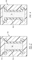
- FIG. 2 is a schematic cross-section of a high-temperature alloy vane segment 50 formed using the teachings herein.
- the vane segment 50 includes an airfoil 52 with an airfoil internal channel 54, an airfoil inner surface 56, and an airfoil outer surface 58.
- An inner shroud 60 and an outer shroud 62 are disposed at an inner end 64 and an outer end 66 of the airfoil 52.
- the shrouds each have a respective backside surface 68.
- Small features 70 may be formed into the airfoil inner surface 56 and / or one or both of the shroud backside surfaces 68.
- These small features 70 may be heat transfer features designed to work together with impingement jets formed by the airfoil impingement insert 30 and / or the shroud impingement plate 32. These small features 70 may take on any shape known to improve heat transfer, including arrays of repeated geometry such as an array of dimples. Alternately there may by various different sizes and shapes to the small features 70 that can be locally tailored as necessary to maximize heat transfer.
- FIGS. 3-16 schematically compare the prior art vane segment casting process and associated core to the process and associated core disclosed herein.
- FIG. 3 schematically depicts the formation of a prior art ceramic casting core 100 within a prior art rigid core die 102.
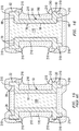
- FIG. 4 is a schematic cross-section of the integral casting core 110 as formed using a flexible liner 112 and an associated rigid core die 114.
- the integral casting core 110 includes a core airfoil portion 116 that defines the airfoil internal channel 54, and a shroud portion 118 (outer shroud portion) extending laterally from the core airfoil portion 116 and having a core shroud backside-shaping surface 120 that defines the backside surface 68 of the outer shroud 62.
- the integral casting core 110 may also include an opposing shroud portion 122 (inner shroud portion) extending laterally from the core airfoil portion 116 and having an opposing core shroud backside-shaping surface 124 that defines the backside surface 68 of the inner shroud 60.
- the core shroud portions 118, 122 may have core shroud features 130 that are configured to form the small features 70.
- the core airfoil portion 116 may have core airfoil features 140 that are configured to form the small features 70 on the airfoil inner surface 56.
- the core shroud features 130 may include a higher elevation 132 and a lower elevation 134 adjacent to the higher elevations 132, where the elevation is relative to the respective core shroud portion 118.
- the rigid core die would need to be separated along line 136.
- the core shroud features 130 are configured as shown, where there is a lower elevation 134 between a higher elevation 132 and a nearest point 138 on a surface 142 of the core airfoil portion 116, an interference between the core shroud features 130 and the opposite features in the rigid core die would prevent lateral movement between the core shroud portion 118 and the rigid core die. This would necessarily prevent movement along line 136.
- the flexible liner is sufficiently flexible that it can be removed from around the core shroud features 130 without causing any damage to them.
- any pattern in the core shroud backside-shaping surface 120 that causes an interference that prevents separation of a rigid core die in this manner but which can be formed with the flexible liner 112 is envisioned.
- One such example would be an array of dimples, or recesses, or trip strips that are not aligned with line 136 etc.
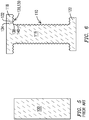
- FIG. 5 is a schematic cross-section of the prior art ceramic casting core 100 of FIG. 3 with the prior art rigid core die 102 remove.
- the prior art ceramic casting core is removed as a green body and may be sintered at this point.
- FIG. 6 is a schematic cross-section of the integral casting core 110 with the flexible liner 112 and the associated rigid core die 114 removed. Likewise, the integral casting core 110 is removed as a green body and may be sintered at this point.
- FIG. 7 is a schematic cross-section of the prior art ceramic casting core 100 of FIG. 5 placed inside a prior art wax die 150, between which a prior art wax pattern 152 has been formed.
- the prior art wax pattern 152 is in the shape of the prior art vane segment 10 to be formed. Due to the geometry of the vane segment 50 to be formed, the geometry of the prior art wax die 150 includes a projection 154 into the prior art wax pattern 152. This projection 154 is a complexity of the prior art wax die 150 that makes its removal more difficult.
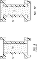
- FIG. 8 is a schematic cross-section of the integral casting core 110 of FIG. 6 inside a wax die 160, between which a wax pattern 162 has been formed.
- the wax pattern 162 is in the shape of the vane segment 50 to be formed. Due to the different shape of the integral casting core 110, the projection 154 of the prior art wax die 150 is not present. The result is an interior shape of the wax die 160 that is much simpler. This increased simplicity makes it easier to remove the wax die 160, and thereby increases available process options.
- FIG. 9 is a schematic cross-section of the prior art ceramic casting core 100 and the prior art wax die 150 of FIG. 7 with the prior art wax die 150 removed.
- FIG. 10 is a schematic cross-section of the integral casting core 110 and the wax pattern 162 of FIG. 8 with the wax die 160 removed.
- FIG. 11 is a schematic cross-section of the prior art ceramic casting core 100 and the prior art wax die 150 of FIG. 9 after a dipping process where a prior art ceramic shell 170 formed. Similar to the projection 154 of the prior art wax die 150, the prior art ceramic shell 170 includes a projection 172.
- FIG. 12 is a schematic cross-section of the integral casting core 110 and the wax pattern 162 of FIG. 10 after the dipping process where a ceramic shell 180 is formed.
- the projection 172 of the prior art ceramic shell 170 is no longer present. In those instances where the ceramic shell 180 forms a lower quality surface than does the integral casting core 110, eliminating the projection 172 reduces the amount of the vane segment 50 that is formed by the ceramic shell 180, and this represents an improvement to the vane segment 50.
- FIG. 13 is a schematic cross-section of the prior art ceramic casting core 100 and the prior art ceramic shell 170 of FIG. 11 , with the prior art wax pattern 152 removed. This leaves a prior art void 190 into which molten alloy will be poured during a single casting pour in order to form the prior art vane segment 10.
- FIG. 14 is a schematic cross-section of the integral casting core 110 and the ceramic shell 180 of FIG. 12 , with the wax pattern 162 removed. This leaves a void 200 into which molten alloy will be poured during a single casting in order to form the monolithic, integral casting core 110.
- FIG. 15 is a schematic cross-section of the prior art ceramic casting core 100 and the prior art ceramic shell 170 of FIG. 13 and the prior art vane segment 10 that has been cast in the prior art void 190.
- the prior art ceramic shell 170 forms all exterior surfaces 210 as well as the backside surfaces 28 of the shrouds 20, 22.
- the prior art ceramic casting core 100 is limited to forming the airfoil inner surface 16.
- FIG. 16 is a schematic cross-section of the integral casting core 110 and the ceramic shell 180 of FIG. 14 and the vane segment 50 that has been cast into the void 200.
- the integral casting core 100 now not only forms the airfoil inner surface 56, but it also forms the backside surfaces 68 of the shrouds 60, 62.
- the ceramic shell 180 is now limited to forming external surfaces 210. This change allows for the surface features 70 to be formed on the backside surfaces 68 of the shrouds 60, 62, via the same casting that forms the airfoil internal channel 54, which has not been done before.
- the surface features 70 will not wash out as may happen when the surface features 70 are formed into the prior art ceramic shell 170 via the prior art wax pattern 152, and will not reposition as may happen when the surface features 70 are formed using a prior art ceramic insert. For this reason the surface features 70 may be made more fine than has been possible until now. Consequently, this represents an improvement in the art.
Landscapes
- Engineering & Computer Science (AREA)
- Mechanical Engineering (AREA)
- Molds, Cores, And Manufacturing Methods Thereof (AREA)
- Turbine Rotor Nozzle Sealing (AREA)
Claims (4)
- Feingussverfahren zur Bildung eines legierten Schaufelsegments eines Gasturbinenmotors (50), wobei das Verfahren die Bildung eines einstückigen, gegossenen Keramikkerns (110) umfasst, der einen Kerntragflächenteil (116) und einen Kerndeckbandteil (118) umfasst, der konfiguriert ist, um wenigstens einen Teil einer hinteren Oberfläche (68) eines Deckbands (62) des Schaufelsegments (50) zu definieren,
wobei der einstückige, gegossene Keramikkern (110) innerhalb einer flexiblen Kerngesenkauskleidung (112) gebildet wird,
wobei in dem Kerndeckbandteil (118) über flexible Auskleidungsdeckbandstrukturen in einer Oberfläche der flexiblen Kerngesenkauskleidung (112), die wenigstens teilweise den Kerndeckbandteil (118) definiert, Kerndeckbandstrukturen (130) gebildet werden, wobei die Kerndeckbandstrukturen (130) konfiguriert sind, um Wärmeübertragungsstrukturen (70) in der hinteren Oberfläche (68) des Deckbands (62) des Schaufelsegments (50) zu bilden,
wobei die Kerndeckbandstrukturen (130) eine Kerndeckbandstruktur mit größerer Erhöhung (132) und eine Kerndeckbandstruktur mit geringerer Erhöhung (134) neben der Kerndeckbandstruktur mit größerer Erhöhung (132) umfassen und Erhöhung relativ zu dem Kerndeckbandteil (118) ist,
wobei die Kerndeckbandstruktur mit geringerer Erhöhung (134) zwischen der Kerndeckbandstruktur mit größerer Erhöhung (132) und einem nächsten Punkt (138) auf einer Oberfläche (142) des Kerntragflächenteils (116) ist,
wobei die Flexibilität der flexiblen Kerngesenkauskleidung (112) das Entfernen der flexiblen Kerngesenkauskleidung (112) aus dem Bereich um die Kerndeckbandstrukturen (130) gestattet, ohne die Kerndeckbandstrukturen (130) zu beschädigen. - Verfahren nach Anspruch 1, wobei der gegossene keramische Kern (110) eine Gesamtheit der hinteren Oberfläche (68) des Deckbands (62) definiert.
- Verfahren nach Anspruch 1, das ferner das Bilden eines Wachsmusters (162) um den gegossenen keramischen Kern (110) und dann das Bilden einer getauchten Keramikschale (180) um das Wachsmuster (162) und den gegossenen Keramikkern (110) umfasst, wobei die Schale (180) konfiguriert ist, um nur externe Oberflächen (210) des Schaufelsegments (50) zu definieren.
- Verfahren nach Anspruch 1, wobei in dem Kerntragflächenteil (116) über flexible Auskleidungsdeckbandstrukturen in einer Oberfläche der flexiblen Kerngesenkauskleidung (112), die wenigstens teilweise den Kerntragflächenteil (116) definiert, Kerntragflächenstrukturen (140) gebildet werden, wobei die Kerntragflächenstrukturen (140) konfiguriert sind, um Wärmeübertragungsstrukturen (70) in einer Oberfläche (56) einer Tragfläche (52) des Schaufelsegments (50) zu bilden.
Applications Claiming Priority (2)
| Application Number | Priority Date | Filing Date | Title |
|---|---|---|---|
| US14/073,922 US9061349B2 (en) | 2013-11-07 | 2013-11-07 | Investment casting method for gas turbine engine vane segment |
| PCT/US2014/062590 WO2015069494A1 (en) | 2013-11-07 | 2014-10-28 | Investment casting method for gas turbine engine vane segment |
Publications (2)
| Publication Number | Publication Date |
|---|---|
| EP3065896A1 EP3065896A1 (de) | 2016-09-14 |
| EP3065896B1 true EP3065896B1 (de) | 2019-01-16 |
Family
ID=51862618
Family Applications (1)
| Application Number | Title | Priority Date | Filing Date |
|---|---|---|---|
| EP14793757.7A Active EP3065896B1 (de) | 2013-11-07 | 2014-10-28 | Feingussverfahren für ein schaufelsegment eines gasturbinenmotors |
Country Status (5)
| Country | Link |
|---|---|
| US (1) | US9061349B2 (de) |
| EP (1) | EP3065896B1 (de) |
| JP (1) | JP2016540150A (de) |
| CN (1) | CN105705265B (de) |
| WO (1) | WO2015069494A1 (de) |
Families Citing this family (3)
| Publication number | Priority date | Publication date | Assignee | Title |
|---|---|---|---|---|
| EP3429779B1 (de) * | 2016-03-18 | 2020-06-03 | Siemens Aktiengesellschaft | Herstellungsverfahren und -werkzeug für keramikkerne |
| US10443415B2 (en) | 2016-03-30 | 2019-10-15 | General Electric Company | Flowpath assembly for a gas turbine engine |
| JP6530157B1 (ja) * | 2017-12-22 | 2019-06-12 | カルソニックカンセイ株式会社 | タービンハウジングの製造方法 |
Citations (1)
| Publication number | Priority date | Publication date | Assignee | Title |
|---|---|---|---|---|
| EP1043479A2 (de) * | 1999-04-06 | 2000-10-11 | General Electric Company | Turbinenwand mit Rillen an der Innenseite |
Family Cites Families (16)
| Publication number | Priority date | Publication date | Assignee | Title |
|---|---|---|---|---|
| US4026659A (en) | 1975-10-16 | 1977-05-31 | Avco Corporation | Cooled composite vanes for turbine nozzles |
| GB2028928B (en) * | 1978-08-17 | 1982-08-25 | Ross Royce Ltd | Aerofoil blade for a gas turbine engine |
| US4232726A (en) * | 1979-03-20 | 1980-11-11 | Anatol Michelson | Process and core box assembly for heatless production of hollow items of mineral granular material |
| JPS6380004A (ja) * | 1986-09-22 | 1988-04-11 | Hitachi Ltd | ガスタ−ビン静翼 |
| US5201847A (en) * | 1991-11-21 | 1993-04-13 | Westinghouse Electric Corp. | Shroud design |
| US5352091A (en) * | 1994-01-05 | 1994-10-04 | United Technologies Corporation | Gas turbine airfoil |
| DE10332904B3 (de) | 2003-07-21 | 2004-12-23 | Daimlerchrysler Ag | Verstärkte Formkerne für den Metallguss, Herstellung und Verwendung |
| US6929054B2 (en) * | 2003-12-19 | 2005-08-16 | United Technologies Corporation | Investment casting cores |
| US7322795B2 (en) * | 2006-01-27 | 2008-01-29 | United Technologies Corporation | Firm cooling method and hole manufacture |
| GB2444483B (en) * | 2006-12-09 | 2010-07-14 | Rolls Royce Plc | A core for use in a casting mould |
| CN100560248C (zh) * | 2007-06-19 | 2009-11-18 | 西安交通大学 | 一种型芯和型壳一体化陶瓷铸型制造方法 |
| US9272324B2 (en) | 2009-12-08 | 2016-03-01 | Siemens Energy, Inc. | Investment casting process for hollow components |
| US20110132562A1 (en) | 2009-12-08 | 2011-06-09 | Merrill Gary B | Waxless precision casting process |
| EP2397653A1 (de) * | 2010-06-17 | 2011-12-21 | Siemens Aktiengesellschaft | Plattformsegment zur Stützung einer Gasturbinenleitschaufel und Kühlungsverfahren |
| US9403208B2 (en) * | 2010-12-30 | 2016-08-02 | United Technologies Corporation | Method and casting core for forming a landing for welding a baffle inserted in an airfoil |
| US20120285652A1 (en) | 2011-05-09 | 2012-11-15 | Fathi Ahmad | Liner for a Die Body |
-
2013
- 2013-11-07 US US14/073,922 patent/US9061349B2/en active Active
-
2014
- 2014-10-28 JP JP2016528190A patent/JP2016540150A/ja not_active Ceased
- 2014-10-28 CN CN201480061190.6A patent/CN105705265B/zh active Active
- 2014-10-28 WO PCT/US2014/062590 patent/WO2015069494A1/en not_active Ceased
- 2014-10-28 EP EP14793757.7A patent/EP3065896B1/de active Active
Patent Citations (1)
| Publication number | Priority date | Publication date | Assignee | Title |
|---|---|---|---|---|
| EP1043479A2 (de) * | 1999-04-06 | 2000-10-11 | General Electric Company | Turbinenwand mit Rillen an der Innenseite |
Also Published As
| Publication number | Publication date |
|---|---|
| WO2015069494A1 (en) | 2015-05-14 |
| US9061349B2 (en) | 2015-06-23 |
| US20150122446A1 (en) | 2015-05-07 |
| CN105705265A (zh) | 2016-06-22 |
| EP3065896A1 (de) | 2016-09-14 |
| JP2016540150A (ja) | 2016-12-22 |
| CN105705265B (zh) | 2019-05-03 |
Similar Documents
| Publication | Publication Date | Title |
|---|---|---|
| EP2841701B1 (de) | Prallkühlung für gasturbinenmotorschaufel | |
| EP1927414B1 (de) | RMC-definierte Spitzenblasungsschlitze für Turbinenschaufeln | |
| US8113780B2 (en) | Castings, casting cores, and methods | |
| US8317475B1 (en) | Turbine airfoil with micro cooling channels | |
| EP2584143A2 (de) | Komponent eines Gasturbinenantrieb | |
| EP2864595B1 (de) | Hybrider gusskern mit aussenluftdichtung | |
| EP2471612B1 (de) | Verfahren und Gusskern zum Formen eines Ansatzes zum Schweißen eines Leitblechs für eine Tragfläche | |
| JP2008151129A (ja) | タービンエンジンコンポーネントおよびその製造方法 | |
| EP3071350B1 (de) | Beschichtete gusskerne und herstellungsverfahren | |
| EP3065896B1 (de) | Feingussverfahren für ein schaufelsegment eines gasturbinenmotors | |
| US20150122450A1 (en) | Ceramic casting core having an integral vane internal core and shroud backside shell for vane segment casting | |
| CN116568455B (zh) | 包括凹槽状顶端下方的腔体的高压涡轮轮叶 | |
| EP3959024B1 (de) | Feingusskern mit kühlfunktionsausrichtführung und zugehörige verfahren | |
| EP3064290B1 (de) | Kern für ein feingussverfahren | |
| WO2019046036A1 (en) | METHOD FOR REALIZING A TURBINE AERODYNAMIC PROFILE | |
| US11759850B2 (en) | Manufacturing aligned cooling features in a core for casting | |
| US20200208530A1 (en) | Method for making a turbine airfoil | |
| EP3533532A1 (de) | Kern für ein feingussverfahren | |
| EP3060363B1 (de) | Verlorene kernformung zur herstellung von kühlkanälen |
Legal Events
| Date | Code | Title | Description |
|---|---|---|---|
| PUAI | Public reference made under article 153(3) epc to a published international application that has entered the european phase |
Free format text: ORIGINAL CODE: 0009012 |
|
| 17P | Request for examination filed |
Effective date: 20160421 |
|
| AK | Designated contracting states |
Kind code of ref document: A1 Designated state(s): AL AT BE BG CH CY CZ DE DK EE ES FI FR GB GR HR HU IE IS IT LI LT LU LV MC MK MT NL NO PL PT RO RS SE SI SK SM TR |
|
| AX | Request for extension of the european patent |
Extension state: BA ME |
|
| STAA | Information on the status of an ep patent application or granted ep patent |
Free format text: STATUS: REQUEST FOR EXAMINATION WAS MADE |
|
| DAX | Request for extension of the european patent (deleted) | ||
| RAP1 | Party data changed (applicant data changed or rights of an application transferred) |
Owner name: SIEMENS AKTIENGESELLSCHAFT |
|
| STAA | Information on the status of an ep patent application or granted ep patent |
Free format text: STATUS: EXAMINATION IS IN PROGRESS |
|
| 17Q | First examination report despatched |
Effective date: 20170904 |
|
| GRAP | Despatch of communication of intention to grant a patent |
Free format text: ORIGINAL CODE: EPIDOSNIGR1 |
|
| STAA | Information on the status of an ep patent application or granted ep patent |
Free format text: STATUS: GRANT OF PATENT IS INTENDED |
|
| INTG | Intention to grant announced |
Effective date: 20180918 |
|
| GRAS | Grant fee paid |
Free format text: ORIGINAL CODE: EPIDOSNIGR3 |
|
| GRAA | (expected) grant |
Free format text: ORIGINAL CODE: 0009210 |
|
| STAA | Information on the status of an ep patent application or granted ep patent |
Free format text: STATUS: THE PATENT HAS BEEN GRANTED |
|
| AK | Designated contracting states |
Kind code of ref document: B1 Designated state(s): AL AT BE BG CH CY CZ DE DK EE ES FI FR GB GR HR HU IE IS IT LI LT LU LV MC MK MT NL NO PL PT RO RS SE SI SK SM TR |
|
| REG | Reference to a national code |
Ref country code: GB Ref legal event code: FG4D |
|
| REG | Reference to a national code |
Ref country code: CH Ref legal event code: EP |
|
| REG | Reference to a national code |
Ref country code: IE Ref legal event code: FG4D |
|
| REG | Reference to a national code |
Ref country code: DE Ref legal event code: R096 Ref document number: 602014040063 Country of ref document: DE |
|
| REG | Reference to a national code |
Ref country code: AT Ref legal event code: REF Ref document number: 1089324 Country of ref document: AT Kind code of ref document: T Effective date: 20190215 |
|
| REG | Reference to a national code |
Ref country code: NL Ref legal event code: MP Effective date: 20190116 |
|
| REG | Reference to a national code |
Ref country code: LT Ref legal event code: MG4D |
|
| PG25 | Lapsed in a contracting state [announced via postgrant information from national office to epo] |
Ref country code: NL Free format text: LAPSE BECAUSE OF FAILURE TO SUBMIT A TRANSLATION OF THE DESCRIPTION OR TO PAY THE FEE WITHIN THE PRESCRIBED TIME-LIMIT Effective date: 20190116 |
|
| REG | Reference to a national code |
Ref country code: AT Ref legal event code: MK05 Ref document number: 1089324 Country of ref document: AT Kind code of ref document: T Effective date: 20190116 |
|
| PG25 | Lapsed in a contracting state [announced via postgrant information from national office to epo] |
Ref country code: PT Free format text: LAPSE BECAUSE OF FAILURE TO SUBMIT A TRANSLATION OF THE DESCRIPTION OR TO PAY THE FEE WITHIN THE PRESCRIBED TIME-LIMIT Effective date: 20190516 Ref country code: PL Free format text: LAPSE BECAUSE OF FAILURE TO SUBMIT A TRANSLATION OF THE DESCRIPTION OR TO PAY THE FEE WITHIN THE PRESCRIBED TIME-LIMIT Effective date: 20190116 Ref country code: LT Free format text: LAPSE BECAUSE OF FAILURE TO SUBMIT A TRANSLATION OF THE DESCRIPTION OR TO PAY THE FEE WITHIN THE PRESCRIBED TIME-LIMIT Effective date: 20190116 Ref country code: ES Free format text: LAPSE BECAUSE OF FAILURE TO SUBMIT A TRANSLATION OF THE DESCRIPTION OR TO PAY THE FEE WITHIN THE PRESCRIBED TIME-LIMIT Effective date: 20190116 Ref country code: FI Free format text: LAPSE BECAUSE OF FAILURE TO SUBMIT A TRANSLATION OF THE DESCRIPTION OR TO PAY THE FEE WITHIN THE PRESCRIBED TIME-LIMIT Effective date: 20190116 Ref country code: NO Free format text: LAPSE BECAUSE OF FAILURE TO SUBMIT A TRANSLATION OF THE DESCRIPTION OR TO PAY THE FEE WITHIN THE PRESCRIBED TIME-LIMIT Effective date: 20190416 Ref country code: SE Free format text: LAPSE BECAUSE OF FAILURE TO SUBMIT A TRANSLATION OF THE DESCRIPTION OR TO PAY THE FEE WITHIN THE PRESCRIBED TIME-LIMIT Effective date: 20190116 |
|
| PG25 | Lapsed in a contracting state [announced via postgrant information from national office to epo] |
Ref country code: GR Free format text: LAPSE BECAUSE OF FAILURE TO SUBMIT A TRANSLATION OF THE DESCRIPTION OR TO PAY THE FEE WITHIN THE PRESCRIBED TIME-LIMIT Effective date: 20190417 Ref country code: IS Free format text: LAPSE BECAUSE OF FAILURE TO SUBMIT A TRANSLATION OF THE DESCRIPTION OR TO PAY THE FEE WITHIN THE PRESCRIBED TIME-LIMIT Effective date: 20190516 Ref country code: RS Free format text: LAPSE BECAUSE OF FAILURE TO SUBMIT A TRANSLATION OF THE DESCRIPTION OR TO PAY THE FEE WITHIN THE PRESCRIBED TIME-LIMIT Effective date: 20190116 Ref country code: BG Free format text: LAPSE BECAUSE OF FAILURE TO SUBMIT A TRANSLATION OF THE DESCRIPTION OR TO PAY THE FEE WITHIN THE PRESCRIBED TIME-LIMIT Effective date: 20190416 Ref country code: LV Free format text: LAPSE BECAUSE OF FAILURE TO SUBMIT A TRANSLATION OF THE DESCRIPTION OR TO PAY THE FEE WITHIN THE PRESCRIBED TIME-LIMIT Effective date: 20190116 Ref country code: HR Free format text: LAPSE BECAUSE OF FAILURE TO SUBMIT A TRANSLATION OF THE DESCRIPTION OR TO PAY THE FEE WITHIN THE PRESCRIBED TIME-LIMIT Effective date: 20190116 |
|
| REG | Reference to a national code |
Ref country code: DE Ref legal event code: R097 Ref document number: 602014040063 Country of ref document: DE |
|
| PG25 | Lapsed in a contracting state [announced via postgrant information from national office to epo] |
Ref country code: RO Free format text: LAPSE BECAUSE OF FAILURE TO SUBMIT A TRANSLATION OF THE DESCRIPTION OR TO PAY THE FEE WITHIN THE PRESCRIBED TIME-LIMIT Effective date: 20190116 Ref country code: CZ Free format text: LAPSE BECAUSE OF FAILURE TO SUBMIT A TRANSLATION OF THE DESCRIPTION OR TO PAY THE FEE WITHIN THE PRESCRIBED TIME-LIMIT Effective date: 20190116 Ref country code: AL Free format text: LAPSE BECAUSE OF FAILURE TO SUBMIT A TRANSLATION OF THE DESCRIPTION OR TO PAY THE FEE WITHIN THE PRESCRIBED TIME-LIMIT Effective date: 20190116 Ref country code: SK Free format text: LAPSE BECAUSE OF FAILURE TO SUBMIT A TRANSLATION OF THE DESCRIPTION OR TO PAY THE FEE WITHIN THE PRESCRIBED TIME-LIMIT Effective date: 20190116 Ref country code: AT Free format text: LAPSE BECAUSE OF FAILURE TO SUBMIT A TRANSLATION OF THE DESCRIPTION OR TO PAY THE FEE WITHIN THE PRESCRIBED TIME-LIMIT Effective date: 20190116 Ref country code: DK Free format text: LAPSE BECAUSE OF FAILURE TO SUBMIT A TRANSLATION OF THE DESCRIPTION OR TO PAY THE FEE WITHIN THE PRESCRIBED TIME-LIMIT Effective date: 20190116 Ref country code: EE Free format text: LAPSE BECAUSE OF FAILURE TO SUBMIT A TRANSLATION OF THE DESCRIPTION OR TO PAY THE FEE WITHIN THE PRESCRIBED TIME-LIMIT Effective date: 20190116 |
|
| PLBE | No opposition filed within time limit |
Free format text: ORIGINAL CODE: 0009261 |
|
| STAA | Information on the status of an ep patent application or granted ep patent |
Free format text: STATUS: NO OPPOSITION FILED WITHIN TIME LIMIT |
|
| PG25 | Lapsed in a contracting state [announced via postgrant information from national office to epo] |
Ref country code: SM Free format text: LAPSE BECAUSE OF FAILURE TO SUBMIT A TRANSLATION OF THE DESCRIPTION OR TO PAY THE FEE WITHIN THE PRESCRIBED TIME-LIMIT Effective date: 20190116 |
|
| 26N | No opposition filed |
Effective date: 20191017 |
|
| PG25 | Lapsed in a contracting state [announced via postgrant information from national office to epo] |
Ref country code: SI Free format text: LAPSE BECAUSE OF FAILURE TO SUBMIT A TRANSLATION OF THE DESCRIPTION OR TO PAY THE FEE WITHIN THE PRESCRIBED TIME-LIMIT Effective date: 20190116 |
|
| PG25 | Lapsed in a contracting state [announced via postgrant information from national office to epo] |
Ref country code: TR Free format text: LAPSE BECAUSE OF FAILURE TO SUBMIT A TRANSLATION OF THE DESCRIPTION OR TO PAY THE FEE WITHIN THE PRESCRIBED TIME-LIMIT Effective date: 20190116 |
|
| PG25 | Lapsed in a contracting state [announced via postgrant information from national office to epo] |
Ref country code: MC Free format text: LAPSE BECAUSE OF FAILURE TO SUBMIT A TRANSLATION OF THE DESCRIPTION OR TO PAY THE FEE WITHIN THE PRESCRIBED TIME-LIMIT Effective date: 20190116 |
|
| REG | Reference to a national code |
Ref country code: CH Ref legal event code: PL |
|
| PG25 | Lapsed in a contracting state [announced via postgrant information from national office to epo] |
Ref country code: CH Free format text: LAPSE BECAUSE OF NON-PAYMENT OF DUE FEES Effective date: 20191031 Ref country code: LU Free format text: LAPSE BECAUSE OF NON-PAYMENT OF DUE FEES Effective date: 20191028 Ref country code: LI Free format text: LAPSE BECAUSE OF NON-PAYMENT OF DUE FEES Effective date: 20191031 |
|
| REG | Reference to a national code |
Ref country code: BE Ref legal event code: MM Effective date: 20191031 |
|
| PG25 | Lapsed in a contracting state [announced via postgrant information from national office to epo] |
Ref country code: BE Free format text: LAPSE BECAUSE OF NON-PAYMENT OF DUE FEES Effective date: 20191031 |
|
| PG25 | Lapsed in a contracting state [announced via postgrant information from national office to epo] |
Ref country code: IE Free format text: LAPSE BECAUSE OF NON-PAYMENT OF DUE FEES Effective date: 20191028 |
|
| REG | Reference to a national code |
Ref country code: DE Ref legal event code: R081 Ref document number: 602014040063 Country of ref document: DE Owner name: SIEMENS ENERGY GLOBAL GMBH & CO. KG, DE Free format text: FORMER OWNER: SIEMENS AKTIENGESELLSCHAFT, 80333 MUENCHEN, DE |
|
| PG25 | Lapsed in a contracting state [announced via postgrant information from national office to epo] |
Ref country code: CY Free format text: LAPSE BECAUSE OF FAILURE TO SUBMIT A TRANSLATION OF THE DESCRIPTION OR TO PAY THE FEE WITHIN THE PRESCRIBED TIME-LIMIT Effective date: 20190116 |
|
| PG25 | Lapsed in a contracting state [announced via postgrant information from national office to epo] |
Ref country code: HU Free format text: LAPSE BECAUSE OF FAILURE TO SUBMIT A TRANSLATION OF THE DESCRIPTION OR TO PAY THE FEE WITHIN THE PRESCRIBED TIME-LIMIT; INVALID AB INITIO Effective date: 20141028 Ref country code: MT Free format text: LAPSE BECAUSE OF FAILURE TO SUBMIT A TRANSLATION OF THE DESCRIPTION OR TO PAY THE FEE WITHIN THE PRESCRIBED TIME-LIMIT Effective date: 20190116 |
|
| PG25 | Lapsed in a contracting state [announced via postgrant information from national office to epo] |
Ref country code: MK Free format text: LAPSE BECAUSE OF FAILURE TO SUBMIT A TRANSLATION OF THE DESCRIPTION OR TO PAY THE FEE WITHIN THE PRESCRIBED TIME-LIMIT Effective date: 20190116 |
|
| REG | Reference to a national code |
Ref country code: GB Ref legal event code: 732E Free format text: REGISTERED BETWEEN 20220901 AND 20220907 |
|
| PGFP | Annual fee paid to national office [announced via postgrant information from national office to epo] |
Ref country code: DE Payment date: 20251028 Year of fee payment: 12 |
|
| PGFP | Annual fee paid to national office [announced via postgrant information from national office to epo] |
Ref country code: GB Payment date: 20251023 Year of fee payment: 12 |
|
| PGFP | Annual fee paid to national office [announced via postgrant information from national office to epo] |
Ref country code: IT Payment date: 20251022 Year of fee payment: 12 |
|
| PGFP | Annual fee paid to national office [announced via postgrant information from national office to epo] |
Ref country code: FR Payment date: 20251027 Year of fee payment: 12 |