EP3065913B1 - Outil d'entraînement de dispositifs de fixation ayant un élément de guidage à chambre de nez automatique - Google Patents
Outil d'entraînement de dispositifs de fixation ayant un élément de guidage à chambre de nez automatique Download PDFInfo
- Publication number
- EP3065913B1 EP3065913B1 EP14766568.1A EP14766568A EP3065913B1 EP 3065913 B1 EP3065913 B1 EP 3065913B1 EP 14766568 A EP14766568 A EP 14766568A EP 3065913 B1 EP3065913 B1 EP 3065913B1
- Authority
- EP
- European Patent Office
- Prior art keywords
- guide member
- fasteners
- fastener
- nose chamber
- bore
- Prior art date
- Legal status (The legal status is an assumption and is not a legal conclusion. Google has not performed a legal analysis and makes no representation as to the accuracy of the status listed.)
- Active
Links
Images


Classifications
-
- B—PERFORMING OPERATIONS; TRANSPORTING
- B25—HAND TOOLS; PORTABLE POWER-DRIVEN TOOLS; MANIPULATORS
- B25C—HAND-HELD NAILING OR STAPLING TOOLS; MANUALLY OPERATED PORTABLE STAPLING TOOLS
- B25C1/00—Hand-held nailing tools; Nail feeding devices
- B25C1/001—Nail feeding devices
-
- B—PERFORMING OPERATIONS; TRANSPORTING
- B25—HAND TOOLS; PORTABLE POWER-DRIVEN TOOLS; MANIPULATORS
- B25C—HAND-HELD NAILING OR STAPLING TOOLS; MANUALLY OPERATED PORTABLE STAPLING TOOLS
- B25C1/00—Hand-held nailing tools; Nail feeding devices
- B25C1/001—Nail feeding devices
- B25C1/005—Nail feeding devices for rows of contiguous nails
-
- B—PERFORMING OPERATIONS; TRANSPORTING
- B25—HAND TOOLS; PORTABLE POWER-DRIVEN TOOLS; MANIPULATORS
- B25C—HAND-HELD NAILING OR STAPLING TOOLS; MANUALLY OPERATED PORTABLE STAPLING TOOLS
- B25C1/00—Hand-held nailing tools; Nail feeding devices
- B25C1/008—Safety devices
-
- B—PERFORMING OPERATIONS; TRANSPORTING
- B25—HAND TOOLS; PORTABLE POWER-DRIVEN TOOLS; MANIPULATORS
- B25C—HAND-HELD NAILING OR STAPLING TOOLS; MANUALLY OPERATED PORTABLE STAPLING TOOLS
- B25C1/00—Hand-held nailing tools; Nail feeding devices
- B25C1/08—Hand-held nailing tools; Nail feeding devices operated by combustion pressure
- B25C1/10—Hand-held nailing tools; Nail feeding devices operated by combustion pressure generated by detonation of a cartridge
- B25C1/18—Details and accessories, e.g. splinter guards, spall minimisers
- B25C1/182—Feeding devices
- B25C1/184—Feeding devices for nails
-
- B—PERFORMING OPERATIONS; TRANSPORTING
- B25—HAND TOOLS; PORTABLE POWER-DRIVEN TOOLS; MANIPULATORS
- B25C—HAND-HELD NAILING OR STAPLING TOOLS; MANUALLY OPERATED PORTABLE STAPLING TOOLS
- B25C5/00—Manually operated portable stapling tools; Hand-held power-operated stapling tools; Staple feeding devices therefor
- B25C5/16—Staple-feeding devices, e.g. with feeding means, supports for staples or accessories concerning feeding devices
Definitions
- the present disclosure generally relates to fastener driving tools, and specifically to such tools designed to operate with fasteners of varying sizes.
- the present driving tool automatically adjusts to differently sized fasteners to reduce jamming, thereby making the tools easier to use and having more accurate fastener delivery.
- Power fastener driving tools are well known. Conventional driving tools are usually portable and are powered pneumatically or by combustion. Sample pneumatic tools are described in U.S. Pat. Nos. 4,932,480 ; 3,552,274 ; and 3,815,475 .
- Such tools incorporate a tool housing enclosing the power source, such as a pneumatic cylinder or a small internal combustion engine.
- the engine is powered by a canister of pressurized fuel gas also called a fuel cell.
- Power is generated from expansion of compressed gasses, either by burning of fuel in a combustion chamber or expansion of air in the pneumatic cylinder.
- a reciprocating piston having an elongated driver blade is actuated by the power source to drive the fasteners into workpieces.
- an interlock prevents firing of the tool unless a workpiece contact element at the end of a nosepiece, or nosepiece assembly, is pressed against a workpiece.
- the fasteners are collated into a strip and positioned within a feed slot or track in a magazine for sequentially advancing each fastener into a driving position within a driving bore of the tool.
- a shear block or guide surface is provided between the magazine and the bore for separating one fastener from adjacent fasteners in the magazine while guiding the fastener into the bore as being driven.
- substantially short nails can occasionally slightly tip or tumble near the magazine feed slot as the fasteners are being driven due to tool orientation, vibrations and unwanted movements of the tool. Such movements cause inaccurate driving of the fasteners and sporadic jamming of the fasteners within the tool.
- One way to reduce tumbling and/or jamming of short fasteners is to provide a pivoting flap or lever in the magazine and shear block for guiding different length fasteners.
- Exemplary models of a fastener-size adjustment device are described in commonly assigned U.S. Pat. No. 5,437,404 and 6,808,101 .
- the adjustment device is pivotally connected to the shear block and care must be taken to insure that a gap between the fastener and the adjustment device does not exist.
- This gap causes the tumbling and jamming of the short fasteners within the tool.
- it is difficult to reduce the gap automatically based on different lengths of the fasteners, and occasionally a user has to rotate the adjustment device manually to clear and prevent the jamming of the short fasteners. Therefore, there is a need for improving the adjustment device to accommodate fasteners of different lengths and prevent the tumbling and jamming of the short or smaller fasteners as they are being driven without requiring manual user intervention.
- US 2010/206934 discloses the features of the preamble of claim 1.
- EP 1 433 572 discloses another example of a fastener driving tool.
- the present disclosure is directed to a fastener driving tool according to claim 1 and having an automatic, adjustable nose chamber guide member for guiding fasteners of at least two different lengths as they are driven by the fastener driving tool.
- the present nose chamber guide member automatically adjusts the size of a nosepiece opening based on a fastener length.
- One aspect of the machine is that, as described in further detail below, there is no need for a user to manipulate the present nose chamber guide member while using the fastener driving tool.
- a consistent biasing action of the present guide member against an inner wall of a nosepiece provides continuous size adjustment between short and long fasteners.
- a gap between the fasteners and the present guide member is reduced automatically when shorter fasteners are present.
- the present guide member is not susceptible to manufacturing tolerance issues. More specifically, the present nose chamber guide member accommodates fasteners of different lengths without having to meet strict tolerance limits and specifications. Unlike pivoting devices that require a perfect alignment of mating surfaces between adjacent moving elements, the present nose chamber guide member is actuated with generous tolerance limits. The present guide member extends and retracts in a transverse direction to the direction of fasteners travelling in the nosepiece. This movement of the present guide member for aligning and guiding the fasteners into a driving bore are achieved without strenuous, narrow manufacturing tolerance limits.
- a fastener driving tool with an improved nose chamber guide member for driving fasteners of at least two different lengths.
- Multiple fasteners in a magazine are guided toward a driving bore to be driven by a driver blade.
- a nosepiece bore a passageway of the fasteners.
- the guide member is operatively connected to the nosepiece and is configured for transitioning between a first position and a second position relative to the nosepiece in a direction transverse to an operational flow direction of the fasteners.
- the guide member In the first position, the guide member is disposed to align with the driving bore for allowing driving of the fasteners having a first length.
- the guide member In the second position, the guide member is disposed out of alignment with respect to the driving bore for allowing driving of the fasteners having a second length, which is longer than the first length.
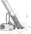
- a fastener driving tool is generally designated 10.
- Such tools are generally well-known in the art, and are described in the above-listed patents.
- the present tool 10 is shown with a nose chamber guide member 12. Tools powered by combustion, compressed air and electric motors are contemplated for use with the present nose chamber guide member.
- the tool 10 is commonly used for driving a fastener 14 into a workpiece 16.
- multiple fasteners 14 are sequentially loaded into a magazine 18 that is in some cases removably attached to the tool 10.
- a nail-type fastener is shown for illustration purposes, any type of fastener that is satisfactorily driven into the workpiece 16 is contemplated, such as brads, staples, tacks and other types known in the art.
- a strip of the fasteners 14 is accommodated in the magazine 18 and successively guided toward a driving bore or passageway 20 having a shape of preferably tubular barrel to be driven by a driver blade 22.
- the present magazine 18 is configured for accommodating strips of at least two different lengths of fasteners 14 and 14' (short and long, unless indicated otherwise, "14" will apply to all lengths).
- Each fastener 14 is sequentially advanced into a driving position within the driving bore or passageway 20.
- a nosepiece 24 at least partially defines the passageway 20.
- the bore 20 extends from the resting position of the driver blade 22 near a body 28 of the tool 10 to an exit 30.
- a rear opening 32 of the bore 20 receives the fasteners 14 from the magazine 18 oriented such that a lower portion or tip 34 of each fastener is facing the workpiece 16 and the fastener is oriented to be generally parallel with the bore.
- WCE work contacting element
- the driver blade 22 retracts up the length of the bore 20 and moves upwardly past the opening 32, the next fastener is forced into the bore by the spring-loaded clip or magazine 18.
- the driver blade 22 travels downwardly in the bore 20 to push down the following fastener 14 into the workpiece 16.
- short fasteners 14 FIGs. 1-3
- they can rotate through the opening 32, blocking the bore 20 below a lower or tip portion 34 of the next fastener 14. This causes jamming of the fasteners 14 and blocks the opening 32, thereby interrupting a smooth operational flow of successive fasteners, and requiring disruptive maintenance and/or disassembly of the tool 10.
- the guide member 12 allows the tool 10 to automatically adjust to different length fasteners.
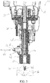
- the improved guide member 12 operatively connected to the nosepiece 24 transitions between a first position and a second position relative to the nosepiece in a direction 40 transverse or generally perpendicular to an operational flow or feeding direction 42 of the fasteners ( FIG. 3 ).
- the present guide member 12 is disposed in a space defined by the nosepiece 24.
- the guide member 12 aligns with the driving bore 20 for allowing driving of the fasteners 14 having a first length (i.e., short).
- a first length i.e., short
- the short fastener 14 travels downwardly through the bore 20 defined in part by the nosepiece 24 and in part by the guide member 12.
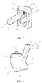
- the guide member 12 is in the second position, as best shown in FIG. 6 , the guide member 12 is disposed out of alignment with respect to the driving bore 20 for allowing driving of the fasteners 14 having a second length, which is longer than the first length, (i.e., long).
- the nose chamber guide member 12 automatically extends and retracts based on the first and second lengths of the fasteners 14 at a substantially right angle to a feeding direction 42 of the fasteners in the magazine 18 ( FIGs. 3 and 6 ).
- the nose chamber guide member 12 is extended to the first position for guiding the fasteners into the driving bore 20 ( FIG. 3 ).
- the guide member 12 is in the first position, at least a portion of the bore 20 is defined by the nosepiece 24 and the nose chamber guide member 12.
- nose chamber guide member 12 transitions into the first position under an action of a return spring 44 ( FIG. 3 ) exerting a biasing force against the guide member.
- the nose chamber guide member 12 is retracted to the second position for guiding the fasteners into the driving bore 20 ( FIG. 6 ).
- the guide member 12 When the guide member 12 is in the second position, at least a portion of the bore 20 is partially defined by the nosepiece 24 alone without the guide member.
- movement of the long fasteners 14' toward the nosepiece 24 forces the nose chamber guide member 12 into the second position, such that the guide member is retracted into a chamber 46 which is attached to the nosepiece 24 and is configured for accommodating the laterally reciprocating guide member.
- the chamber 46 is constructed and arranged adjacent to the opening 32 of the bore 20 near a lower portion 48 of the nosepiece.
- the nose chamber guide member 12 includes a slanted outer face 50 angled from a first edge 52 to an opposite second edge 54 for facilitating movement of the fasteners 14'. More specifically, as the long fasteners 14' move toward the bore 20, the fasteners push a protruding portion 56 of the outer face 50 to overcome the force of the spring 44, such that the guide member 12 is retracted away from an inner wall 58 of the nosepiece 24, thereby forcing the guide member 12 to be in the second position ( FIG. 6 ). However, when the guide member 12 is in the first position, the protruding portion 56 directly biases against the inner wall 58 of the nosepiece 24 under the action of the return spring 44 ( FIG. 3 ).
- first edge 52 of the nose chamber guide member 12 defines part of a fastener pathway toward the exit 30 and an upper portion 60 is inclined to facilitate a fastener location in the driving bore 20.
- the possibility of jamming is reduced by incorporating this feature. For example, as the fastener 14 moves downwardly under the action of the driver blade 22, the lower portion 34 of the fastener is properly guided by the inclined upper portion 60 even if the fastener tips or tumbles near the opening 32.
- first guide rod 62 and a second guide rod 64 further included in the guide member 12 are a first guide rod 62 and a second guide rod 64, where the second guide rod is shorter than the first guide rod. Due to this length difference, the longer guide rod 62 protrudes out of the chamber 46 when the guide member 12 is in the second position, thereby indicating to the user that the long fasteners 14' are used in the tool 10 ( FIG. 5 ). Conversely, the first guide rod 62 recedes into the chamber 46 when the guide member 12 is in the first position ( FIG. 2 ). These rods 62, 64 orient and align the guide member 12 properly to reciprocate within the chamber 46 between the first and second positions under the action of the return spring 44 ( FIGs. 3 and 6 ).
- the first rod 62 has a rectangular prism shape and the second rod 64 has a cylindrical tube shape
- any suitable geometric shape such as a hexagonal prism or a cone shape, is also contemplated.
- the guide member 12 is operatively connected to the nosepiece 24 for allowing longitudinal movement of the guide member between the first and second positions.
- a support pin 66 ( FIG. 6 ) is disposed within at least one of the chamber 46 and the nosepiece 24 for preventing unwanted movement of the guide member 12 within the tool 10.
- a guide pin 68 is optionally provided on the guide member 12 for defining a seat for the return spring 44 that biases against the inner wall 58 of the guide member 12.
- the first rod 62 is optionally provided with a grip bar 70 (shown in phantom), extending transversely, preferably at a right angle to an axis of the first rod 62. While the shape, construction and location of the grip bar 70 may vary with the application, the grip bar facilitates manual clearing of the tool in the event fasteners become lodged in the bore 20, or there are only a few remaining fasteners 14 in the magazine 18. If a jam occurs, the user grasps the grip bar 70 to pull the guide member to the position shown in FIG. 6 , opening the bore 20. At the same time, the tool 10 is tilted or oriented so that the previously jammed fastener exits the outlet 30 by gravity.
- a grip bar 70 shown in phantom
Landscapes
- Engineering & Computer Science (AREA)
- Mechanical Engineering (AREA)
- Chemical & Material Sciences (AREA)
- Combustion & Propulsion (AREA)
- Portable Nailing Machines And Staplers (AREA)
Claims (13)
- Outil d'enfoncement d'éléments d'enfoncement (10) pour l'enfoncement d'éléments d'enfoncement (14, 14') d'au moins deux longueurs différentes lorsque les éléments d'enfoncement dans un magasin (18) sont guidés vers un alésage d'enfoncement (20) pour être enfoncés par une lame d'enfoncement (22), comprenant :un embout (24) définissant un passage des éléments d'enfoncement étant alimentés à partir dudit magasin ;un élément de guidage de chambre d'embout (12) relié de manière opérationnelle à ladite pièce d'embout (24) et configuré pour la transition entre une première position et une deuxième position ; etdans lequel, dans ladite première position, ledit élément de guidage de chambre d'embout (12) est disposé pour être aligné avec ledit alésage d'enfoncement (20) permettant l'enfoncement des éléments d'enfoncement ayant une première longueur, et dans ladite deuxième position, ledit élément de guidage de chambre d'embout (12) est disposé hors alignement par rapport audit alésage d'enfoncement (20) permettant l'enfoncement des éléments d'enfoncement ayant une deuxième longueur, qui est plus longue que la première longueur,caractérisé en ce que ladite transition entre ladite première position et ladite deuxième position est relative à ladite pièce d'embout (24) dans une direction transversale à une direction de flux opérationnel (42) des éléments d'enfoncement (14, 14') à partir dudit magasin (18).
- Outil d'enfoncement d'éléments d'enfoncement (10) selon la revendication 1, dans lequel ledit élément de guidage de chambre d'embout (12) s'étend et se rétracte automatiquement sur base des première et deuxième longueurs des éléments d'enfoncement (14, 14') à un angle sensiblement droit par rapport à une direction d'alimentation (42) des éléments d'enfoncement dans ledit magasin (18).
- Outil d'enfoncement d'éléments d'enfoncement (10) selon la revendication 1, dans lequel ledit élément de guidage de chambre d'embout (12) peut être étendu sous une force de sollicitation vers ladite première position pour le guidage des éléments d'enfoncement (14, 14') ayant la première longueur dans ledit alésage d'enfoncement (20).
- Outil d'enfoncement d'éléments d'enfoncement (10) selon la revendication 1, dans lequel ledit élément de guidage de chambre d'embout (12) est rétractable vers ladite deuxième position pour le guidage des éléments d'enfoncement (14, 14') ayant la deuxième longueur dans ledit alésage d'enfoncement (20), lors de l'insertion des éléments d'enfoncement de deuxième longueur.
- Outil d'enfoncement d'éléments d'enfoncement (10) selon la revendication 1, dans lequel au moins une partie dudit alésage d'enfoncement (20) est définie par ledit élément de guidage de chambre d'embout (12) lorsque ledit élément de guidage est dans ladite première position.
- Outil d'enfoncement d'éléments d'enfoncement (10) selon la revendication 5, dans lequel au moins une partie dudit alésage d'enfoncement (20) est définie par ladite pièce d'embout (24) sans ledit élément de guidage de chambre d'embout (12) lorsque ledit élément de guidage est dans ladite deuxième position.
- Outil d'enfoncement d'éléments d'enfoncement (10) selon la revendication 1, dans lequel ledit élément de guidage de chambre d'embout (12) passe dans ladite première position sous une action d'un ressort de rappel (44) exerçant une force de sollicitation contre ledit élément de guidage.
- Outil d'enfoncement d'éléments d'enfoncement (10) selon la revendication 1, dans lequel le mouvement des éléments d'enfoncement (14, 14') ayant la deuxième longueur vers un alésage d'élément d'enfoncement dans ladite pièce d'embout force ledit élément de guidage de chambre d'embout (12) dans ladite deuxième position.
- Outil d'enfoncement d'éléments d'enfoncement (10) selon la revendication 1, dans lequel ledit élément de guidage de chambre d'embout (12) comprend une face extérieure inclinée (50) formant un angle à partir d'un premier bord (52) vers un deuxième bord opposé permettant le mouvement des éléments d'enfoncement (14, 14') de la deuxième longueur.
- Outil d'enfoncement d'éléments d'enfoncement (10) selon la revendication 1, dans lequel un bord dudit élément de guidage de chambre d'embout (12) définit une partie d'un trajet d'éléments d'enfoncement et une partie supérieure (60) est inclinée pour faciliter un emplacement d'éléments d'enfoncement dans ledit alésage d'enfoncement (20).
- Outil d'enfoncement d'éléments d'enfoncement (10) selon la revendication 1, dans lequel ledit élément de guidage de chambre d'embout (12) est sollicité par ressort et comprend une première tige de guidage (62) et une deuxième tige de guidage (64), ladite deuxième tige de guidage étant plus courte que ladite première tige de guidage.
- Outil d'enfoncement d'éléments d'enfoncement (10) selon la revendication 11, dans lequel au moins une parmi lesdites tiges de guidage (62, 64) fournit une indication visuelle de la longueur des éléments d'enfoncement (14, 14') dans ledit magasin (18).
- Outil d'enfoncement d'éléments d'enfoncement (10) selon la revendication 1, dans lequel ledit élément de guidage de chambre d'embout (12) comprend une broche de guidage (68) définissant un siège pour un ressort de rappel (44) qui sollicite contre ledit élément de guidage.
Priority Applications (1)
| Application Number | Priority Date | Filing Date | Title |
|---|---|---|---|
| EP21166093.1A EP3881972A1 (fr) | 2013-11-06 | 2014-08-21 | Nez pour outil de fixation |
Applications Claiming Priority (2)
| Application Number | Priority Date | Filing Date | Title |
|---|---|---|---|
| US14/073,021 US9527196B2 (en) | 2013-11-06 | 2013-11-06 | Fastener driving tool with an automatic nose chamber guide member |
| PCT/US2014/052204 WO2015069363A1 (fr) | 2013-11-06 | 2014-08-21 | Outil d'entraînement de dispositifs de fixation ayant un élément de guidage à chambre de nez automatique |
Related Child Applications (2)
| Application Number | Title | Priority Date | Filing Date |
|---|---|---|---|
| EP21166093.1A Division EP3881972A1 (fr) | 2013-11-06 | 2014-08-21 | Nez pour outil de fixation |
| EP21166093.1A Division-Into EP3881972A1 (fr) | 2013-11-06 | 2014-08-21 | Nez pour outil de fixation |
Publications (2)
| Publication Number | Publication Date |
|---|---|
| EP3065913A1 EP3065913A1 (fr) | 2016-09-14 |
| EP3065913B1 true EP3065913B1 (fr) | 2022-10-05 |
Family
ID=51542437
Family Applications (2)
| Application Number | Title | Priority Date | Filing Date |
|---|---|---|---|
| EP21166093.1A Pending EP3881972A1 (fr) | 2013-11-06 | 2014-08-21 | Nez pour outil de fixation |
| EP14766568.1A Active EP3065913B1 (fr) | 2013-11-06 | 2014-08-21 | Outil d'entraînement de dispositifs de fixation ayant un élément de guidage à chambre de nez automatique |
Family Applications Before (1)
| Application Number | Title | Priority Date | Filing Date |
|---|---|---|---|
| EP21166093.1A Pending EP3881972A1 (fr) | 2013-11-06 | 2014-08-21 | Nez pour outil de fixation |
Country Status (6)
| Country | Link |
|---|---|
| US (2) | US9527196B2 (fr) |
| EP (2) | EP3881972A1 (fr) |
| AU (1) | AU2014347252B2 (fr) |
| CA (1) | CA2924047C (fr) |
| NZ (2) | NZ733142A (fr) |
| WO (1) | WO2015069363A1 (fr) |
Families Citing this family (31)
| Publication number | Priority date | Publication date | Assignee | Title |
|---|---|---|---|---|
| DE102012209416A1 (de) * | 2012-06-04 | 2013-12-05 | Hilti Aktiengesellschaft | Magazinvorsatz und Befestigungssystem |
| US11077542B2 (en) * | 2013-10-31 | 2021-08-03 | Stanley Fastening Systems, L.P. | Metal connector adaptor for a fastening tool |
| US9527196B2 (en) * | 2013-11-06 | 2016-12-27 | Illinois Tool Works Inc. | Fastener driving tool with an automatic nose chamber guide member |
| CA2953140C (fr) * | 2014-06-20 | 2022-12-13 | Glenn J. Tebo | Clip de plancher |
| US20170050304A1 (en) * | 2015-08-19 | 2017-02-23 | Wen-Sheng Huang | Barrel assembly of a nail gun |
| US9993912B2 (en) * | 2015-09-30 | 2018-06-12 | Samson Power Tool Co. Ltd. | Nail pushing device for nail gun |
| US10350741B2 (en) * | 2015-11-02 | 2019-07-16 | Black & Decker Inc. | Powered nail driver with a nail placement assembly |
| US10668608B2 (en) | 2016-02-10 | 2020-06-02 | Illinois Tool Works Inc. | Fastener driving tool |
| US11325235B2 (en) | 2016-06-28 | 2022-05-10 | Black & Decker, Inc. | Push-on support member for fastening tools |
| US10493607B2 (en) * | 2016-06-28 | 2019-12-03 | Black & Decker, Inc. | Concrete nailer having magazine cutout for deep tracks |
| US11267114B2 (en) | 2016-06-29 | 2022-03-08 | Black & Decker, Inc. | Single-motion magazine retention for fastening tools |
| US10987790B2 (en) | 2016-06-30 | 2021-04-27 | Black & Decker Inc. | Cordless concrete nailer with improved power take-off mechanism |
| US11279013B2 (en) | 2016-06-30 | 2022-03-22 | Black & Decker, Inc. | Driver rebound plate for a fastening tool |
| US11400572B2 (en) | 2016-06-30 | 2022-08-02 | Black & Decker, Inc. | Dry-fire bypass for a fastening tool |
| US20180093370A1 (en) * | 2016-10-04 | 2018-04-05 | Stanley Black & Decker, Inc. | Fastening Tool with Contact Arm and Multi-Fastener Guide |
| US10926385B2 (en) | 2017-02-24 | 2021-02-23 | Black & Decker, Inc. | Contact trip having magnetic filter |
| EP3398721B1 (fr) * | 2017-05-05 | 2026-02-25 | Illinois Tool Works Inc. | Outil de fixation combine |
| US10926391B2 (en) | 2017-11-14 | 2021-02-23 | Illinois Tool Works Inc. | Powered fastener driving tool having hook assemblies |
| USD854820S1 (en) | 2017-11-14 | 2019-07-30 | Illinois Tool Works Inc. | Fastener driving tool belt hook |
| USD855431S1 (en) | 2017-11-14 | 2019-08-06 | Illinois Tool Works Inc. | Fastener driving tool pipe hook |
| EP3666468A1 (fr) * | 2018-12-10 | 2020-06-17 | Hilti Aktiengesellschaft | Dispositif de séparation, chargeur et système de fixation |
| US11130221B2 (en) | 2019-01-31 | 2021-09-28 | Milwaukee Electric Tool Corporation | Powered fastener driver |
| US11433521B2 (en) | 2019-03-13 | 2022-09-06 | Milwaukee Electric Tool Corporation | Powered fastener driver |
| US10987791B2 (en) * | 2019-04-01 | 2021-04-27 | Testo Industry Corp. | Probe assembly of a metal connector nailer |
| TWI869395B (zh) * | 2019-07-31 | 2025-01-11 | 日商工機控股股份有限公司 | 釘打機 |
| JP2021186932A (ja) * | 2020-05-29 | 2021-12-13 | 工機ホールディングス株式会社 | 打込機 |
| EP4537985A3 (fr) * | 2022-02-21 | 2025-07-30 | Kyocera Senco Industrial Tools, Inc. | Guide de fixation de magasin pour outil d'entraînement de fixation |
| US12521855B2 (en) | 2023-04-14 | 2026-01-13 | Illinois Tool Works Inc. | Fastener driving tool having a retractable probe assembly |
| US20240375257A1 (en) * | 2023-05-12 | 2024-11-14 | Illinois Tool Works Inc. | Apparatus for driving fasteners |
| USD1119548S1 (en) | 2024-01-08 | 2026-03-24 | Techtronic Cordless Gp | Workpiece contact element for a fastener driver |
| US12466041B2 (en) | 2024-01-08 | 2025-11-11 | Techtronic Cordless Gp | Workpiece contact element for a powered fastener driver |
Citations (1)
| Publication number | Priority date | Publication date | Assignee | Title |
|---|---|---|---|---|
| EP1433572A1 (fr) * | 2001-10-03 | 2004-06-30 | Max Kabushiki Kaisha | Chargeur d'elements de fixation pour machine de fixation |
Family Cites Families (35)
| Publication number | Priority date | Publication date | Assignee | Title |
|---|---|---|---|---|
| US3552274A (en) | 1968-05-27 | 1971-01-05 | Signode Corp | Pneumatic piston return system for impact tools |
| US3815475A (en) | 1972-11-20 | 1974-06-11 | Signode Corp | Fastener driving tool with improved piston return |
| US3834602A (en) * | 1973-01-26 | 1974-09-10 | Fastener Corp | Fastener driving tool |
| US4174802A (en) * | 1976-03-24 | 1979-11-20 | Bruno Maestri | Magazine device for continuously feeding nails into a nail driving machine |
| US4304349B1 (en) * | 1979-10-09 | 1996-02-27 | Duo Fast Cord | Fastener driving tool |
| US4403722A (en) | 1981-01-22 | 1983-09-13 | Signode Corporation | Combustion gas powered fastener driving tool |
| US4483474A (en) | 1981-01-22 | 1984-11-20 | Signode Corporation | Combustion gas-powered fastener driving tool |
| US4389012A (en) * | 1981-04-22 | 1983-06-21 | Duo-Fast Corporation | Fastener tool loading assembly |
| US4483473A (en) | 1983-05-02 | 1984-11-20 | Signode Corporation | Portable gas-powered fastener driving tool |
| US4932480A (en) | 1988-12-16 | 1990-06-12 | Illinois Tool Works Inc. | Driving tool with air-cooled bumper |
| US5197646A (en) | 1992-03-09 | 1993-03-30 | Illinois Tool Works Inc. | Combustion-powered tool assembly |
| US5263439A (en) | 1992-11-13 | 1993-11-23 | Illinois Tool Works Inc. | Fuel system for combustion-powered, fastener-driving tool |
| US5335800A (en) * | 1993-07-06 | 1994-08-09 | Liu Chung Ho | Magazine for rivet gun |
| US5437404A (en) | 1993-07-13 | 1995-08-01 | Illinois Tool Works Inc. | Adjustable shear block assembly |
| US5452835A (en) * | 1994-08-01 | 1995-09-26 | Illinois Tool Works Inc. | Positioning mechanism for powered fastener-driving tool |
| US5813588A (en) * | 1996-10-09 | 1998-09-29 | Lin; George | Magazine assembly for fastener driving tools |
| US6053389A (en) * | 1998-08-05 | 2000-04-25 | Sup Drogon Enterprise Co., Ltd. | Nailing gun magazine specially designed for big nail set |
| US6279808B1 (en) * | 1999-07-27 | 2001-08-28 | Mark E. Larsen | Nail guide mechanism for a nail gun |
| TW542069U (en) * | 2001-11-21 | 2003-07-11 | Mu-Yu Chen | Nail cartridge for nailing gun suitable for multiple dimensions |
| US6808101B2 (en) | 2002-05-24 | 2004-10-26 | Illinois Tool Works Inc. | Framing tool with automatic fastener-size adjustment |
| US6739490B1 (en) * | 2002-06-24 | 2004-05-25 | Illinois Tool Works Inc. | Fastener supply and positioning mechanism for a tool |
| US7028875B1 (en) * | 2002-09-18 | 2006-04-18 | Black & Decker Inc. | Nail checker assembly |
| US20040084499A1 (en) * | 2002-11-04 | 2004-05-06 | Chien-Fang Tsai | Pneumatic nailing machine |
| US6729524B1 (en) * | 2002-12-27 | 2004-05-04 | Bentley Fastening Tools Co., Ltd. | Nail cartridge for a nail gun |
| JP4420205B2 (ja) * | 2004-04-28 | 2010-02-24 | マックス株式会社 | 釘打機の釘案内装置 |
| JP4400587B2 (ja) * | 2006-03-16 | 2010-01-20 | 日立工機株式会社 | 打込機 |
| US8684245B2 (en) * | 2006-10-20 | 2014-04-01 | Stanley Fastening Systems, L.P. | Fastener driving device with mechanisms to limit movement of nails |
| TW200840689A (en) * | 2007-04-10 | 2008-10-16 | kun-quan Zhou | Nail magazine capable of placing single and plural nail slices |
| FR2920332B1 (fr) | 2007-09-05 | 2010-04-23 | Spit Soc Prospect Inv Techn | Outil de fixation pour la fixation d'elements de differentes longueurs |
| US9486904B2 (en) * | 2012-05-31 | 2016-11-08 | Black & Decker Inc. | Fastening tool nosepiece insert |
| US9498871B2 (en) * | 2012-05-31 | 2016-11-22 | Black & Decker Inc. | Power tool raving spring curl trip actuator |
| US9827658B2 (en) * | 2012-05-31 | 2017-11-28 | Black & Decker Inc. | Power tool having latched pusher assembly |
| DE102012209416A1 (de) * | 2012-06-04 | 2013-12-05 | Hilti Aktiengesellschaft | Magazinvorsatz und Befestigungssystem |
| US9796072B2 (en) | 2013-08-30 | 2017-10-24 | Illinois Tool Works Inc. | Staple tool |
| US9527196B2 (en) * | 2013-11-06 | 2016-12-27 | Illinois Tool Works Inc. | Fastener driving tool with an automatic nose chamber guide member |
-
2013
- 2013-11-06 US US14/073,021 patent/US9527196B2/en active Active
-
2014
- 2014-08-21 EP EP21166093.1A patent/EP3881972A1/fr active Pending
- 2014-08-21 AU AU2014347252A patent/AU2014347252B2/en active Active
- 2014-08-21 WO PCT/US2014/052204 patent/WO2015069363A1/fr not_active Ceased
- 2014-08-21 EP EP14766568.1A patent/EP3065913B1/fr active Active
- 2014-08-21 NZ NZ733142A patent/NZ733142A/en unknown
- 2014-08-21 CA CA2924047A patent/CA2924047C/fr active Active
- 2014-08-21 NZ NZ717925A patent/NZ717925A/en unknown
-
2016
- 2016-12-21 US US15/386,542 patent/US10144120B2/en active Active
Patent Citations (1)
| Publication number | Priority date | Publication date | Assignee | Title |
|---|---|---|---|---|
| EP1433572A1 (fr) * | 2001-10-03 | 2004-06-30 | Max Kabushiki Kaisha | Chargeur d'elements de fixation pour machine de fixation |
Also Published As
| Publication number | Publication date |
|---|---|
| EP3881972A1 (fr) | 2021-09-22 |
| EP3065913A1 (fr) | 2016-09-14 |
| NZ717925A (en) | 2017-08-25 |
| US20170100826A1 (en) | 2017-04-13 |
| WO2015069363A1 (fr) | 2015-05-14 |
| US10144120B2 (en) | 2018-12-04 |
| NZ733142A (en) | 2019-04-26 |
| CA2924047C (fr) | 2019-01-15 |
| US9527196B2 (en) | 2016-12-27 |
| AU2014347252B2 (en) | 2017-06-08 |
| CA2924047A1 (fr) | 2015-05-14 |
| US20150122867A1 (en) | 2015-05-07 |
| AU2014347252A1 (en) | 2016-04-07 |
Similar Documents
| Publication | Publication Date | Title |
|---|---|---|
| EP3065913B1 (fr) | Outil d'entraînement de dispositifs de fixation ayant un élément de guidage à chambre de nez automatique | |
| CA2422447C (fr) | Outil de charpentage a reglage automatique de la dimension des fixations | |
| AU2016206349B2 (en) | Fastener feeder delay for fastener driving tool | |
| CA2694967C (fr) | Colonnette guide d'actionneur pour un mandrin de pose et de depose de piece de fixation | |
| US8276798B2 (en) | Feeder mechanism retention device for fastener driving tool | |
| US20130175314A1 (en) | Fastening tool with blind guide work contact tip | |
| KR20070114275A (ko) | 매거진 내에 드라이버 블레이드 블로킹 메커니즘을 구비한파워 네일러 | |
| US7070079B2 (en) | No-mar tip for fastening tool | |
| US11045935B2 (en) | Nosepiece assembly with a head spring for use in a powered nailer |
Legal Events
| Date | Code | Title | Description |
|---|---|---|---|
| PUAI | Public reference made under article 153(3) epc to a published international application that has entered the european phase |
Free format text: ORIGINAL CODE: 0009012 |
|
| 17P | Request for examination filed |
Effective date: 20160406 |
|
| AK | Designated contracting states |
Kind code of ref document: A1 Designated state(s): AL AT BE BG CH CY CZ DE DK EE ES FI FR GB GR HR HU IE IS IT LI LT LU LV MC MK MT NL NO PL PT RO RS SE SI SK SM TR |
|
| AX | Request for extension of the european patent |
Extension state: BA ME |
|
| DAX | Request for extension of the european patent (deleted) | ||
| STAA | Information on the status of an ep patent application or granted ep patent |
Free format text: STATUS: EXAMINATION IS IN PROGRESS |
|
| 17Q | First examination report despatched |
Effective date: 20200706 |
|
| GRAP | Despatch of communication of intention to grant a patent |
Free format text: ORIGINAL CODE: EPIDOSNIGR1 |
|
| STAA | Information on the status of an ep patent application or granted ep patent |
Free format text: STATUS: GRANT OF PATENT IS INTENDED |
|
| INTG | Intention to grant announced |
Effective date: 20220504 |
|
| GRAS | Grant fee paid |
Free format text: ORIGINAL CODE: EPIDOSNIGR3 |
|
| GRAA | (expected) grant |
Free format text: ORIGINAL CODE: 0009210 |
|
| STAA | Information on the status of an ep patent application or granted ep patent |
Free format text: STATUS: THE PATENT HAS BEEN GRANTED |
|
| AK | Designated contracting states |
Kind code of ref document: B1 Designated state(s): AL AT BE BG CH CY CZ DE DK EE ES FI FR GB GR HR HU IE IS IT LI LT LU LV MC MK MT NL NO PL PT RO RS SE SI SK SM TR |
|
| REG | Reference to a national code |
Ref country code: GB Ref legal event code: FG4D |
|
| REG | Reference to a national code |
Ref country code: CH Ref legal event code: EP |
|
| REG | Reference to a national code |
Ref country code: AT Ref legal event code: REF Ref document number: 1522460 Country of ref document: AT Kind code of ref document: T Effective date: 20221015 |
|
| REG | Reference to a national code |
Ref country code: DE Ref legal event code: R096 Ref document number: 602014085142 Country of ref document: DE |
|
| REG | Reference to a national code |
Ref country code: IE Ref legal event code: FG4D |
|
| REG | Reference to a national code |
Ref country code: LT Ref legal event code: MG9D |
|
| REG | Reference to a national code |
Ref country code: NL Ref legal event code: MP Effective date: 20221005 |
|
| REG | Reference to a national code |
Ref country code: AT Ref legal event code: MK05 Ref document number: 1522460 Country of ref document: AT Kind code of ref document: T Effective date: 20221005 |
|
| PG25 | Lapsed in a contracting state [announced via postgrant information from national office to epo] |
Ref country code: NL Free format text: LAPSE BECAUSE OF FAILURE TO SUBMIT A TRANSLATION OF THE DESCRIPTION OR TO PAY THE FEE WITHIN THE PRESCRIBED TIME-LIMIT Effective date: 20221005 |
|
| PG25 | Lapsed in a contracting state [announced via postgrant information from national office to epo] |
Ref country code: SE Free format text: LAPSE BECAUSE OF FAILURE TO SUBMIT A TRANSLATION OF THE DESCRIPTION OR TO PAY THE FEE WITHIN THE PRESCRIBED TIME-LIMIT Effective date: 20221005 Ref country code: PT Free format text: LAPSE BECAUSE OF FAILURE TO SUBMIT A TRANSLATION OF THE DESCRIPTION OR TO PAY THE FEE WITHIN THE PRESCRIBED TIME-LIMIT Effective date: 20230206 Ref country code: NO Free format text: LAPSE BECAUSE OF FAILURE TO SUBMIT A TRANSLATION OF THE DESCRIPTION OR TO PAY THE FEE WITHIN THE PRESCRIBED TIME-LIMIT Effective date: 20230105 Ref country code: LT Free format text: LAPSE BECAUSE OF FAILURE TO SUBMIT A TRANSLATION OF THE DESCRIPTION OR TO PAY THE FEE WITHIN THE PRESCRIBED TIME-LIMIT Effective date: 20221005 Ref country code: FI Free format text: LAPSE BECAUSE OF FAILURE TO SUBMIT A TRANSLATION OF THE DESCRIPTION OR TO PAY THE FEE WITHIN THE PRESCRIBED TIME-LIMIT Effective date: 20221005 Ref country code: ES Free format text: LAPSE BECAUSE OF FAILURE TO SUBMIT A TRANSLATION OF THE DESCRIPTION OR TO PAY THE FEE WITHIN THE PRESCRIBED TIME-LIMIT Effective date: 20221005 Ref country code: AT Free format text: LAPSE BECAUSE OF FAILURE TO SUBMIT A TRANSLATION OF THE DESCRIPTION OR TO PAY THE FEE WITHIN THE PRESCRIBED TIME-LIMIT Effective date: 20221005 |
|
| PG25 | Lapsed in a contracting state [announced via postgrant information from national office to epo] |
Ref country code: RS Free format text: LAPSE BECAUSE OF FAILURE TO SUBMIT A TRANSLATION OF THE DESCRIPTION OR TO PAY THE FEE WITHIN THE PRESCRIBED TIME-LIMIT Effective date: 20221005 Ref country code: PL Free format text: LAPSE BECAUSE OF FAILURE TO SUBMIT A TRANSLATION OF THE DESCRIPTION OR TO PAY THE FEE WITHIN THE PRESCRIBED TIME-LIMIT Effective date: 20221005 Ref country code: LV Free format text: LAPSE BECAUSE OF FAILURE TO SUBMIT A TRANSLATION OF THE DESCRIPTION OR TO PAY THE FEE WITHIN THE PRESCRIBED TIME-LIMIT Effective date: 20221005 Ref country code: IS Free format text: LAPSE BECAUSE OF FAILURE TO SUBMIT A TRANSLATION OF THE DESCRIPTION OR TO PAY THE FEE WITHIN THE PRESCRIBED TIME-LIMIT Effective date: 20230205 Ref country code: HR Free format text: LAPSE BECAUSE OF FAILURE TO SUBMIT A TRANSLATION OF THE DESCRIPTION OR TO PAY THE FEE WITHIN THE PRESCRIBED TIME-LIMIT Effective date: 20221005 Ref country code: GR Free format text: LAPSE BECAUSE OF FAILURE TO SUBMIT A TRANSLATION OF THE DESCRIPTION OR TO PAY THE FEE WITHIN THE PRESCRIBED TIME-LIMIT Effective date: 20230106 |
|
| REG | Reference to a national code |
Ref country code: DE Ref legal event code: R097 Ref document number: 602014085142 Country of ref document: DE |
|
| P01 | Opt-out of the competence of the unified patent court (upc) registered |
Effective date: 20230606 |
|
| PG25 | Lapsed in a contracting state [announced via postgrant information from national office to epo] |
Ref country code: SM Free format text: LAPSE BECAUSE OF FAILURE TO SUBMIT A TRANSLATION OF THE DESCRIPTION OR TO PAY THE FEE WITHIN THE PRESCRIBED TIME-LIMIT Effective date: 20221005 Ref country code: RO Free format text: LAPSE BECAUSE OF FAILURE TO SUBMIT A TRANSLATION OF THE DESCRIPTION OR TO PAY THE FEE WITHIN THE PRESCRIBED TIME-LIMIT Effective date: 20221005 Ref country code: EE Free format text: LAPSE BECAUSE OF FAILURE TO SUBMIT A TRANSLATION OF THE DESCRIPTION OR TO PAY THE FEE WITHIN THE PRESCRIBED TIME-LIMIT Effective date: 20221005 Ref country code: DK Free format text: LAPSE BECAUSE OF FAILURE TO SUBMIT A TRANSLATION OF THE DESCRIPTION OR TO PAY THE FEE WITHIN THE PRESCRIBED TIME-LIMIT Effective date: 20221005 Ref country code: CZ Free format text: LAPSE BECAUSE OF FAILURE TO SUBMIT A TRANSLATION OF THE DESCRIPTION OR TO PAY THE FEE WITHIN THE PRESCRIBED TIME-LIMIT Effective date: 20221005 |
|
| PLBE | No opposition filed within time limit |
Free format text: ORIGINAL CODE: 0009261 |
|
| STAA | Information on the status of an ep patent application or granted ep patent |
Free format text: STATUS: NO OPPOSITION FILED WITHIN TIME LIMIT |
|
| PG25 | Lapsed in a contracting state [announced via postgrant information from national office to epo] |
Ref country code: SK Free format text: LAPSE BECAUSE OF FAILURE TO SUBMIT A TRANSLATION OF THE DESCRIPTION OR TO PAY THE FEE WITHIN THE PRESCRIBED TIME-LIMIT Effective date: 20221005 Ref country code: AL Free format text: LAPSE BECAUSE OF FAILURE TO SUBMIT A TRANSLATION OF THE DESCRIPTION OR TO PAY THE FEE WITHIN THE PRESCRIBED TIME-LIMIT Effective date: 20221005 |
|
| 26N | No opposition filed |
Effective date: 20230706 |
|
| PG25 | Lapsed in a contracting state [announced via postgrant information from national office to epo] |
Ref country code: SI Free format text: LAPSE BECAUSE OF FAILURE TO SUBMIT A TRANSLATION OF THE DESCRIPTION OR TO PAY THE FEE WITHIN THE PRESCRIBED TIME-LIMIT Effective date: 20221005 |
|
| PG25 | Lapsed in a contracting state [announced via postgrant information from national office to epo] |
Ref country code: MC Free format text: LAPSE BECAUSE OF FAILURE TO SUBMIT A TRANSLATION OF THE DESCRIPTION OR TO PAY THE FEE WITHIN THE PRESCRIBED TIME-LIMIT Effective date: 20221005 |
|
| REG | Reference to a national code |
Ref country code: CH Ref legal event code: PL |
|
| PG25 | Lapsed in a contracting state [announced via postgrant information from national office to epo] |
Ref country code: MC Free format text: LAPSE BECAUSE OF FAILURE TO SUBMIT A TRANSLATION OF THE DESCRIPTION OR TO PAY THE FEE WITHIN THE PRESCRIBED TIME-LIMIT Effective date: 20221005 |
|
| PG25 | Lapsed in a contracting state [announced via postgrant information from national office to epo] |
Ref country code: LU Free format text: LAPSE BECAUSE OF NON-PAYMENT OF DUE FEES Effective date: 20230821 |
|
| PG25 | Lapsed in a contracting state [announced via postgrant information from national office to epo] |
Ref country code: LU Free format text: LAPSE BECAUSE OF NON-PAYMENT OF DUE FEES Effective date: 20230821 Ref country code: CH Free format text: LAPSE BECAUSE OF NON-PAYMENT OF DUE FEES Effective date: 20230831 |
|
| REG | Reference to a national code |
Ref country code: BE Ref legal event code: MM Effective date: 20230831 |
|
| REG | Reference to a national code |
Ref country code: IE Ref legal event code: MM4A |
|
| PG25 | Lapsed in a contracting state [announced via postgrant information from national office to epo] |
Ref country code: IT Free format text: LAPSE BECAUSE OF FAILURE TO SUBMIT A TRANSLATION OF THE DESCRIPTION OR TO PAY THE FEE WITHIN THE PRESCRIBED TIME-LIMIT Effective date: 20221005 |
|
| PG25 | Lapsed in a contracting state [announced via postgrant information from national office to epo] |
Ref country code: IE Free format text: LAPSE BECAUSE OF NON-PAYMENT OF DUE FEES Effective date: 20230821 |
|
| PG25 | Lapsed in a contracting state [announced via postgrant information from national office to epo] |
Ref country code: IE Free format text: LAPSE BECAUSE OF NON-PAYMENT OF DUE FEES Effective date: 20230821 |
|
| PG25 | Lapsed in a contracting state [announced via postgrant information from national office to epo] |
Ref country code: BE Free format text: LAPSE BECAUSE OF NON-PAYMENT OF DUE FEES Effective date: 20230831 |
|
| PG25 | Lapsed in a contracting state [announced via postgrant information from national office to epo] |
Ref country code: BG Free format text: LAPSE BECAUSE OF FAILURE TO SUBMIT A TRANSLATION OF THE DESCRIPTION OR TO PAY THE FEE WITHIN THE PRESCRIBED TIME-LIMIT Effective date: 20221005 |
|
| PG25 | Lapsed in a contracting state [announced via postgrant information from national office to epo] |
Ref country code: BG Free format text: LAPSE BECAUSE OF FAILURE TO SUBMIT A TRANSLATION OF THE DESCRIPTION OR TO PAY THE FEE WITHIN THE PRESCRIBED TIME-LIMIT Effective date: 20221005 |
|
| PG25 | Lapsed in a contracting state [announced via postgrant information from national office to epo] |
Ref country code: CY Free format text: LAPSE BECAUSE OF FAILURE TO SUBMIT A TRANSLATION OF THE DESCRIPTION OR TO PAY THE FEE WITHIN THE PRESCRIBED TIME-LIMIT; INVALID AB INITIO Effective date: 20140821 |
|
| PG25 | Lapsed in a contracting state [announced via postgrant information from national office to epo] |
Ref country code: HU Free format text: LAPSE BECAUSE OF FAILURE TO SUBMIT A TRANSLATION OF THE DESCRIPTION OR TO PAY THE FEE WITHIN THE PRESCRIBED TIME-LIMIT; INVALID AB INITIO Effective date: 20140821 |
|
| PGFP | Annual fee paid to national office [announced via postgrant information from national office to epo] |
Ref country code: DE Payment date: 20250827 Year of fee payment: 12 |
|
| PGFP | Annual fee paid to national office [announced via postgrant information from national office to epo] |
Ref country code: GB Payment date: 20250827 Year of fee payment: 12 |
|
| PGFP | Annual fee paid to national office [announced via postgrant information from national office to epo] |
Ref country code: FR Payment date: 20250825 Year of fee payment: 12 |
|
| PG25 | Lapsed in a contracting state [announced via postgrant information from national office to epo] |
Ref country code: TR Free format text: LAPSE BECAUSE OF FAILURE TO SUBMIT A TRANSLATION OF THE DESCRIPTION OR TO PAY THE FEE WITHIN THE PRESCRIBED TIME-LIMIT Effective date: 20221005 |