EP3066007B1 - Gegenläufiges rotorsystem mit stationärem standrohr - Google Patents
Gegenläufiges rotorsystem mit stationärem standrohr Download PDFInfo
- Publication number
- EP3066007B1 EP3066007B1 EP14860965.4A EP14860965A EP3066007B1 EP 3066007 B1 EP3066007 B1 EP 3066007B1 EP 14860965 A EP14860965 A EP 14860965A EP 3066007 B1 EP3066007 B1 EP 3066007B1
- Authority
- EP
- European Patent Office
- Prior art keywords
- rotor
- standpipe
- assembly
- rotor shaft
- shaft
- Prior art date
- Legal status (The legal status is an assumption and is not a legal conclusion. Google has not performed a legal analysis and makes no representation as to the accuracy of the status listed.)
- Active
Links
Images


Classifications
-
- B—PERFORMING OPERATIONS; TRANSPORTING
- B64—AIRCRAFT; AVIATION; COSMONAUTICS
- B64C—AEROPLANES; HELICOPTERS
- B64C27/00—Rotorcraft; Rotors peculiar thereto
- B64C27/04—Helicopters
- B64C27/08—Helicopters with two or more rotors
- B64C27/10—Helicopters with two or more rotors arranged coaxially
-
- B—PERFORMING OPERATIONS; TRANSPORTING
- B64—AIRCRAFT; AVIATION; COSMONAUTICS
- B64C—AEROPLANES; HELICOPTERS
- B64C27/00—Rotorcraft; Rotors peculiar thereto
- B64C27/04—Helicopters
- B64C27/12—Rotor drives
-
- B—PERFORMING OPERATIONS; TRANSPORTING
- B64—AIRCRAFT; AVIATION; COSMONAUTICS
- B64D—EQUIPMENT FOR FITTING IN OR TO AIRCRAFT; FLIGHT SUITS; PARACHUTES; ARRANGEMENT OR MOUNTING OF POWER PLANTS OR PROPULSION TRANSMISSIONS IN AIRCRAFT
- B64D35/00—Transmitting power from power plants to propellers or rotors; Arrangements of transmissions
- B64D35/04—Transmitting power from power plants to propellers or rotors; Arrangements of transmissions characterised by the transmission driving a plurality of propellers or rotors
-
- B—PERFORMING OPERATIONS; TRANSPORTING
- B64—AIRCRAFT; AVIATION; COSMONAUTICS
- B64D—EQUIPMENT FOR FITTING IN OR TO AIRCRAFT; FLIGHT SUITS; PARACHUTES; ARRANGEMENT OR MOUNTING OF POWER PLANTS OR PROPULSION TRANSMISSIONS IN AIRCRAFT
- B64D35/00—Transmitting power from power plants to propellers or rotors; Arrangements of transmissions
- B64D35/04—Transmitting power from power plants to propellers or rotors; Arrangements of transmissions characterised by the transmission driving a plurality of propellers or rotors
- B64D35/06—Transmitting power from power plants to propellers or rotors; Arrangements of transmissions characterised by the transmission driving a plurality of propellers or rotors the propellers or rotors being counter-rotating
Definitions
- the subject matter disclosed herein relates to the art of rotary wing aircraft and, more specifically, to coaxial multi-rotor systems for rotary wing aircraft.
- rotary power is transmitted from an engine through a gearbox into the rotor system.
- the gearbox transfers power to a lower rotor shaft to drive a lower rotor assembly and to an upper rotor shaft coaxial with the lower rotor shaft to drive the upper rotor assembly.
- the systems typically include several sets of bearings between the upper rotor shaft and lower rotor shaft to transfer loads between the shafts and to the housings.
- the bearings and controls for the upper rotor assembly drive an increased diameter for the upper rotor shaft, and thus the lower rotor shaft, which increases drag during operation.
- many coaxial rotor systems include an aerodynamic fairing positioned between the upper rotor assembly and the lower rotor assembly.
- Typical systems attach to the upper and lower rotor shafts and include a significant derotation mechanism to prevent the fairing from rotating with respect to the airframe, and to keep the fairing oriented in a selected direction.
- US 2013/052034 A1 discloses a stationary ground tube for use in an aircraft rotor fairing which includes a first cylindrical portion including a first bore aligned along a longitudinal axis, the cylindrical body portion having a tubular body from a first end to a second end, and a second cylindrical portion coupled to the first cylindrical portion, the second cylindrical portion including a second bore aligned along the longitudinal axis.
- the second cylindrical portion is coupled to the aircraft rotor fairing via at least one attachment device.
- the upper rotor shaft and upper control rods are contained within an interior cavity of a ground tube while the lower rotor shaft rotates outside the ground tube. Bearings may be provided for maintaining the position of the lower rotor shaft with respect to the stationary ground tube in addition to reduction of friction.
- US 5 351 913 A discloses a coaxial transmission/center hub subassembly for a rotor assembly having ducted, coaxial counter-rotating rotors which includes a single stage transmission, a transmission housing, and a center hub support structure that are structurally and functionally interactive.
- the transmission housing includes upper and lower standpipe housings secured in combination with a middle housing.
- the single stage transmission includes an input pinion gear rotatably mounted in combination with the middle housing, and upper and lower spiral bevel gears rotatably coupled in combination with the input pinion gear to provide counter-rotation thereof.
- the spiral bevel gears include integral rotor shafts, respectively, rotatably mounted in the standpipe housings.
- Standpipe bearings are mounted against the internal surface of the upper and lower standpipe housings and are operative to facilitate rotary motion of the respective rotor shafts while transmitting rotor bending loads to the upper and lower standpipe housings.
- the invention relates to a coaxial, dual rotor system connected to a gearbox according to the appended claims.
- FIG. 1 Shown in FIG. 1 is schematic view of an embodiment of a rotary wing aircraft, in this embodiment a helicopter 10.
- the helicopter 10 includes an airframe 12 with an extending tail 14.
- a dual, counter rotating coaxial main rotor assembly 18 is located at the airframe 12 and rotates about a main rotor axis 20.
- the main rotor assembly 18 is driven by a power source, for example, an engine 24 via a gearbox 26.
- the main rotor assembly 18 includes an upper rotor assembly 28 driven in a first direction 30 about the main rotor axis 20, and a lower rotor assembly 32 driven in a second direction 34 about the main rotor axis 20, opposite to the first direction 30. While, in FIG.
- the first direction 30 is illustrated as counter-clockwise and the second direction 34 is illustrated as clockwise (when looking downward), it is to be appreciated that in some embodiments the directions of rotation of the upper rotor assembly 28 and lower rotor assembly 32 may be reversed.
- Each of the upper rotor assembly 28 and the lower rotor assembly 32 include a plurality of rotor blades 36 secured to a rotor hub 38.
- the helicopter 10 further includes a translational thrust system 40 located at the extending tail 14 to provide translational thrust for the helicopter 10.
- the translational thrust system 40 includes a propeller rotor 42 connected to and driven by the engine 24 via the gearbox 26. While shown in the context of a pusher-prop configuration, it is understood that the propeller rotor 42 could also be more conventional puller prop or could be variably facing so as to provide yaw control in addition to or instead of translational thrust.
- the upper rotor assembly 28 is driven by an upper rotor shaft 44 axially supported at the gearbox 26 by an upper rotor bearing 46.
- a lower bull gear 48 mated to the upper rotor shaft 44 is driven via a lower output pinion 50 thus driving rotation of the upper rotor shaft 44 and the upper rotor assembly 28.
- lower rotor assembly 32 is connected to and driven by a lower rotor shaft 52, which is coaxial with the upper rotor shaft 44 and located radially outboard of the upper rotor shaft 44.
- the lower rotor shaft 52 is axially supported at the gearbox 26 by a lower rotor bearing 54 set, and is connected to an upper bull gear 56 driven by an upper output pinion 58. While the gearbox 26 in the present embodiment includes bull gears 48 and 56, it is merely exemplary. Other gear types, such as spiral bevel gears, may be utilized.
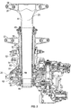
- a stationary standpipe 60 is coaxial with the upper rotor shaft 44 and the lower rotor shaft 52, and is located radially between the upper rotor shaft 44 and the lower rotor shaft 52.
- the standpipe 60 is fixed to a non-rotating part of the gearbox 26, for example, a gearbox housing 62, via, in some embodiments a spline connection 64.
- the standpipe 60 extends along the main rotor axis 20, terminating between the upper rotor assembly 28 and the lower rotor assembly 32.
- the upper rotor shaft 44 transfers lift loads to the gearbox 26 via the upper rotor bearing 46 at a base 66 of the upper rotor shaft 44.
- Upper rotor assembly 28 moment loads are coupled at the upper rotor bearing 46 and at an intershaft shear bearing 68 located between the upper rotor shaft 44 and the standpipe 60 at an upper end of the lower rotor shaft 52 to transfer loads from the upper rotor shaft into the standpipe.
- the lower rotor shaft 44 transfers lift loads into the gearbox 26 via lower rotor bearing 54 located at a base of the lower rotor shaft 44.
- Lower rotor assembly 32 moment loads are coupled between the lower shaft bearings 80 and 82 at the lower rotor shaft 52.
- the standpipe 60 provides a nonrotating structure at which to mount an aerodynamic fairing 74 between the upper rotor assembly 28 and the lower rotor assembly 32.
- the standpipe 60 may include, for example, an arrangement of studs or bolts 76, which align with openings (not shown) in the fairing 74 and are used to secure the fairing 74 to the standpipe 60. While shown as empty, it is understood that the fairing 74 could be solid, or can house electronics or other boxes.
- a fairing 74 is installed on the standpipe 60, it is to be appreciated that the standpipe 60 may be utilized to locate and secure various nonrotating elements, such as RADAR domes, slip rings, LIDAR equipment, or other electronic or mechanical equipment.
Landscapes
- Engineering & Computer Science (AREA)
- Mechanical Engineering (AREA)
- Aviation & Aerospace Engineering (AREA)
- Shafts, Cranks, Connecting Bars, And Related Bearings (AREA)
- Retarders (AREA)
Claims (13)
- Koaxiales duales Rotorsystem, das mit einem Getriebe verbunden ist, wobei das System Folgendes umfasst:eine erste Rotorbaugruppe (28), die an einer Rotorachse (20) angeordnet ist und eine erste axiale Last und ein erstes Moment verleiht;eine erste Rotorwelle (44), die mit der ersten Rotorbaugruppe (28) an der Rotorachse (20) wirkverbunden ist, um eine Rotation der ersten Rotorbaugruppe um die Rotorachse anzutreiben;eine erste Lagerbaugruppe, die ein erstes Rotorwellenlager (46) umfasst, das an der Basis (66) der ersten Rotorwelle (44) angeordnet ist und diese lagert und das Getriebe (26) mit der ersten Rotorwelle (44) verbindet, und die die erste axiale Last von der ersten Rotorwelle (44) an das Getriebe (26) überträgt;eine zweiteRotorbaugruppe (32), die an der Rotorachse (20) angeordnet ist und eine zweite axiale Last und ein zweites Moment verleiht;eine zweite Rotorwelle (52), die mit der zweiten Rotorbaugruppe (32) an der Rotorachse (20) wirkverbunden ist, um eine Rotation der zweiten Rotorbaugruppe um die Rotorachse anzutreiben, wobei die zweite Rotorwelle (52) koaxial und radial versetzt zu der ersten Rotorwelle (44) ist;eine zweite Lagerbaugruppe, die ein zweites Rotorwellenlager (54) umfasst, das an der Basis der zweiten Rotorwelle (52) angeordnet ist und diese lagert und das Getriebe (26) mit der zweiten Rotorwelle (52) verbindet, und die die zweite axiale Last von der zweiten Rotorwelle (52) an das Getriebe (26) überträgt;ein nichtrotierendes Standrohr (60), das an der Rotorachse (20) radial zwischen der ersten Rotorwelle (44) und der zweiten Rotorwelle (52) angeordnet ist; undeine Zwischenwellenlagerbaugruppe (68), die am oberen Ende der zweiten Rotorwelle (52) zwischen der ersten Rotorwelle (44) und dem Standrohr (60) angeordnet ist und die das erste und zweite Moment unter Verwendung der ersten und zweiten Lagerbaugruppe von der ersten Rotorbaugruppe (28) und der zweiten Rotorbaugruppe (32) an das Standrohr (60) überträgt.
- Rotorsystem nach Anspruch 1, wobei das Standrohr (60) entlang der Rotorachse zwischen der ersten Rotorbaugruppe (28) und der zweiten Rotorbaugruppe (32) endet.
- Rotorsystem nach Anspruch 2, ferner umfassend eine aerodynamische Verkleidung (74), die an dem Standrohr (60) zwischen der ersten Rotorbaugruppe (28) und der zweiten Rotorbaugruppe (32) gesichert ist.
- Rotorsystem nach Anspruch 3, wobei die aerodynamische Verkleidung (74) über eine Vielzahl von Befestigungselementen (76), die sich von dem Standrohr (60) erstreckt, gesichert ist.
- Rotorsystem nach Anspruch 1, ferner umfassend ein oder mehrere Lager (68), die zwischen der ersten Rotorwelle (44) und dem Standrohr (60) angeordnet sind, um Lasten zwischen diesen zu übertragen.
- Rotorsystem nach Anspruch 1, ferner umfassend ein oder mehrere Lager, die zwischen der zweiten Rotorwelle (52) und dem Standrohr (60) angeordnet sind, um Lasten zwischen diesen zu übertragen.
- Rotorsystem nach Anspruch 1, wobei die erste Rotorbaugruppe (28) in einer ersten Richtung um die Rotorachse dreht und die zweite Rotorbaugruppe (32) in einer zweiten Richtung entgegengesetzt zur ersten Richtung um die Rotorachse dreht.
- Rotorsystem nach Anspruch 1, wobei das Standrohr (60) an einer Basis des Standrohrs gesichert ist, um dessen Rotation um die Rotorachse zu verhindern.
- Rotorsystem nach Anspruch 1, wobei die erste Rotorwelle (44) radial einwärts von der zweiten Rotorwelle (52) angeordnet ist.
- Drehflügler (10) mit dualem koaxialem Rotor, umfassend:ein Flugwerk (12);ein Antriebssystem, das das Getriebe (26), das am Flugwerk (12) angeordnet ist, beinhaltet; undein duales koaxiales Rotorsystem (18) nach einem der Ansprüche 1-9, das mit dem Antriebssystem wirkverbunden ist.
- Drehflügler nach Anspruch 10, wobei das Standrohr (60) an einer Basis des Standrohrs gesichert ist, um dessen Rotation um die Rotorachse zu verhindern.
- Drehflügler nach Anspruch 11, wobei das Standrohr (60) an einer Komponente des Antriebssystems gesichert ist und/oder wobei das Standrohr (60) über eine Keilverbindung an seiner Basis gesichert ist.
- Drehflügler nach Anspruch 10, wobei die erste Rotorbaugruppe (28) eine obere Rotorbaugruppe ist und die zweite Rotorbaugruppe (32) eine untere Rotorbaugruppe ist.
Applications Claiming Priority (2)
| Application Number | Priority Date | Filing Date | Title |
|---|---|---|---|
| US14/071,987 US9623964B2 (en) | 2013-11-05 | 2013-11-05 | Counter-rotating rotor system with stationary standpipe |
| PCT/US2014/062839 WO2015069514A1 (en) | 2013-11-05 | 2014-10-29 | Counter-rotating rotor system with stationary standpipe |
Publications (3)
| Publication Number | Publication Date |
|---|---|
| EP3066007A1 EP3066007A1 (de) | 2016-09-14 |
| EP3066007A4 EP3066007A4 (de) | 2017-07-05 |
| EP3066007B1 true EP3066007B1 (de) | 2019-04-10 |
Family
ID=53007190
Family Applications (1)
| Application Number | Title | Priority Date | Filing Date |
|---|---|---|---|
| EP14860965.4A Active EP3066007B1 (de) | 2013-11-05 | 2014-10-29 | Gegenläufiges rotorsystem mit stationärem standrohr |
Country Status (3)
| Country | Link |
|---|---|
| US (1) | US9623964B2 (de) |
| EP (1) | EP3066007B1 (de) |
| WO (1) | WO2015069514A1 (de) |
Families Citing this family (16)
| Publication number | Priority date | Publication date | Assignee | Title |
|---|---|---|---|---|
| US10065730B2 (en) * | 2014-01-22 | 2018-09-04 | Bell Helicopter Textron Inc. | Active vibration control system with non-concentric revolving masses |
| WO2016053408A1 (en) | 2014-10-01 | 2016-04-07 | Sikorsky Aircraft Corporation | Acoustic signature variation of aircraft utilizing a clutch |
| US10899438B2 (en) | 2015-11-12 | 2021-01-26 | Sikorsky Aircraft Corporation | Seals for rotor system fairings |
| JP6510960B2 (ja) * | 2015-11-20 | 2019-05-08 | 川崎重工業株式会社 | ヘリコプタのマストスペーサ、およびこれを備えるヘリコプタの動力伝達装置並びにヘリコプタ |
| US20170341733A1 (en) * | 2016-05-27 | 2017-11-30 | Sikorsky Aircraft Corporation | Rotor head for prop-rotor |
| FR3061141B1 (fr) * | 2016-12-22 | 2019-01-25 | Airbus Helicopters | Carter de boite de transmission de puissance, boite de puissance et aeronef |
| US11932380B2 (en) | 2017-03-15 | 2024-03-19 | Textron Innovations Inc. | Vibration isolation systems for compound helicopters |
| US20180265186A1 (en) | 2017-03-15 | 2018-09-20 | Bell Helicopter Textron Inc. | Vibration Isolation Systems for Advancing Blade Concept Rotorcraft |
| US10017247B1 (en) * | 2017-06-02 | 2018-07-10 | Bell Helicopter Textron Inc. | Rotor mast assembly |
| DE102017219831B4 (de) * | 2017-11-08 | 2021-07-15 | Zf Friedrichshafen Ag | System zur Lagerung einer Rotorwelle |
| US11002309B2 (en) * | 2018-07-31 | 2021-05-11 | Lockheed Martin Corporation | Hybrid rotor shaft for a vertical take-off and landing (VTOL) aircraft |
| CN109866932A (zh) * | 2019-04-19 | 2019-06-11 | 深圳市边锋智驱科技有限公司 | 螺旋桨组件及飞行器 |
| US11498673B2 (en) | 2019-09-26 | 2022-11-15 | Textron Innovations Inc. | Light communication slip ring |
| RU2729900C9 (ru) * | 2019-12-30 | 2020-11-26 | Акционерное общество "Национальный центр вертолетостроения им. М.Л. Миля и Н.И. Камова" (АО "НЦВ Миль и Камов") | Система привода соосных несущих винтов вертолёта с опорной мачтой |
| US11161606B2 (en) * | 2020-01-15 | 2021-11-02 | Textron Innovations Inc. | Flexured standpipes for aircraft propulsion assemblies |
| US11879526B2 (en) * | 2021-03-17 | 2024-01-23 | Terry Gordon Wood | Transmission with alternating rotary disks |
Family Cites Families (17)
| Publication number | Priority date | Publication date | Assignee | Title |
|---|---|---|---|---|
| US2481290A (en) * | 1947-08-30 | 1949-09-06 | Armstrong Siddeley Motors Ltd | Drive for contrarotating propellers |
| US2948490A (en) * | 1953-08-11 | 1960-08-09 | Verdugo Juan Munoz | Helicopter |
| US4531692A (en) * | 1982-03-15 | 1985-07-30 | Ernesto Mateus | Helicopter flight control and transmission system |
| US4525123A (en) * | 1982-05-06 | 1985-06-25 | Alfred Curci | Rotary wing aircraft |
| US5058824A (en) * | 1989-12-21 | 1991-10-22 | United Technologies Corporation | Servo control system for a co-axial rotary winged aircraft |
| DE69332527T2 (de) * | 1992-06-22 | 2003-08-21 | United Technologies Corp., Stratford | Antriebsstranganordnung für unbemanntes Fluggerät |
| US5351913A (en) | 1992-06-22 | 1994-10-04 | United Technologies Corporation | Coaxial transmission/center hub subassembly for a rotor assembly having ducted, coaxial counter-rotating rotors |
| US5791592A (en) | 1995-01-18 | 1998-08-11 | Nolan; Herbert M. | Helicopter with coaxial counter-rotating dual rotors and no tail rotor |
| US6886777B2 (en) | 2001-02-14 | 2005-05-03 | Airscooter Corporation | Coaxial helicopter |
| US6540570B1 (en) | 2002-01-16 | 2003-04-01 | Robert C. Eakin | Counter-rotating transmission |
| US7118340B2 (en) | 2004-09-10 | 2006-10-10 | Sikorsky Aircraft Corporation | Swashplate and pitch link arrangement for a coaxial counter rotating rotor system |
| US7946526B2 (en) | 2004-11-05 | 2011-05-24 | Nachman Zimet | Rotary-wing vehicle system |
| US7607607B2 (en) * | 2005-05-26 | 2009-10-27 | Sikorsky Aircraft Corporation | De-rotation system suitable for use with a shaft fairing system |
| US7621480B2 (en) | 2005-05-26 | 2009-11-24 | Sikorsky Aircraft Corporation | De-rotation system for a counter-rotating, coaxial rotor hub shaft fairing |
| US7229251B2 (en) * | 2005-05-31 | 2007-06-12 | Sikorsky Aircraft Corporation | Rotor hub fairing system for a counter-rotating, coaxial rotor system |
| US8858179B2 (en) | 2009-12-18 | 2014-10-14 | Sikorsky Aircraft Corporation | Helicopter rotor control system |
| US9199720B2 (en) | 2011-08-31 | 2015-12-01 | Sikorsky Aircraft Corporation | Non-rotating stationary ground tube for a wind fairing |
-
2013
- 2013-11-05 US US14/071,987 patent/US9623964B2/en active Active
-
2014
- 2014-10-29 EP EP14860965.4A patent/EP3066007B1/de active Active
- 2014-10-29 WO PCT/US2014/062839 patent/WO2015069514A1/en not_active Ceased
Non-Patent Citations (1)
| Title |
|---|
| None * |
Also Published As
| Publication number | Publication date |
|---|---|
| EP3066007A4 (de) | 2017-07-05 |
| US20150125299A1 (en) | 2015-05-07 |
| US9623964B2 (en) | 2017-04-18 |
| EP3066007A1 (de) | 2016-09-14 |
| WO2015069514A1 (en) | 2015-05-14 |
Similar Documents
| Publication | Publication Date | Title |
|---|---|---|
| US9623964B2 (en) | Counter-rotating rotor system with stationary standpipe | |
| US10053212B2 (en) | Transmission for coaxial multi-rotor system | |
| US20170158323A1 (en) | Tiltrotor with Inboard Engines | |
| US20160207619A1 (en) | Light weight propulsor gearbox | |
| US10676182B2 (en) | Tilting coaxial rotor for a rotary wing aircraft | |
| US10752343B2 (en) | Electric propulsion system for a rotary wing aircraft | |
| US11338915B2 (en) | Rotor systems and methods | |
| EP2873613B1 (de) | Gegenläufiges Rotorsystem mit statischem Mast | |
| CA1258846A (en) | Aircraft propeller system | |
| US11161606B2 (en) | Flexured standpipes for aircraft propulsion assemblies | |
| WO2019157588A1 (en) | Transmission system for aircraft structure | |
| US10724625B2 (en) | Torsionally compliant geartrain carrier assembly | |
| EP4328133B1 (de) | Drehwelle für ein flugzeug | |
| US10745117B2 (en) | Radially compliant quill shaft | |
| EP3539868B1 (de) | Flexible kopplung für standrohrbaugruppe | |
| US20180281937A1 (en) | Rigid rotor head with tension torsion (tt) strap retention | |
| US12054276B2 (en) | Installation of gear assemblies in aircraft gearboxes | |
| US10941836B2 (en) | Rotorcraft internal transfer member transmission | |
| US12576964B1 (en) | Helicopter pitch controls | |
| EP2873612B1 (de) | Gegenläufiges Rotorsystem mit Verkleidung | |
| RU2729900C1 (ru) | Система привода соосных несущих винтов вертолёта с опорной мачтой | |
| US10654566B2 (en) | Integrated main rotor hub and shaft | |
| NO344389B1 (en) | A system for variable blade pitch control and autorotation for electrically powered rotorcraft |
Legal Events
| Date | Code | Title | Description |
|---|---|---|---|
| PUAI | Public reference made under article 153(3) epc to a published international application that has entered the european phase |
Free format text: ORIGINAL CODE: 0009012 |
|
| 17P | Request for examination filed |
Effective date: 20160531 |
|
| AK | Designated contracting states |
Kind code of ref document: A1 Designated state(s): AL AT BE BG CH CY CZ DE DK EE ES FI FR GB GR HR HU IE IS IT LI LT LU LV MC MK MT NL NO PL PT RO RS SE SI SK SM TR |
|
| AX | Request for extension of the european patent |
Extension state: BA ME |
|
| RIN1 | Information on inventor provided before grant (corrected) |
Inventor name: BASKIN, BRYAN KENNETH Inventor name: WEDMAN, KENDALL Inventor name: GARCIA, TODD A. Inventor name: DUELLO, CHARLES |
|
| DAX | Request for extension of the european patent (deleted) | ||
| A4 | Supplementary search report drawn up and despatched |
Effective date: 20170602 |
|
| RIC1 | Information provided on ipc code assigned before grant |
Ipc: B64C 27/12 20060101ALI20170529BHEP Ipc: B64D 35/06 20060101ALI20170529BHEP Ipc: B64C 27/10 20060101AFI20170529BHEP |
|
| REG | Reference to a national code |
Ref country code: DE Ref legal event code: R079 Ref document number: 602014044649 Country of ref document: DE Free format text: PREVIOUS MAIN CLASS: B64C0007000000 Ipc: B64C0027100000 |
|
| RIC1 | Information provided on ipc code assigned before grant |
Ipc: B64D 35/06 20060101ALI20180907BHEP Ipc: B64C 27/12 20060101ALI20180907BHEP Ipc: B64C 27/10 20060101AFI20180907BHEP |
|
| GRAP | Despatch of communication of intention to grant a patent |
Free format text: ORIGINAL CODE: EPIDOSNIGR1 |
|
| STAA | Information on the status of an ep patent application or granted ep patent |
Free format text: STATUS: GRANT OF PATENT IS INTENDED |
|
| INTG | Intention to grant announced |
Effective date: 20181022 |
|
| GRAS | Grant fee paid |
Free format text: ORIGINAL CODE: EPIDOSNIGR3 |
|
| GRAA | (expected) grant |
Free format text: ORIGINAL CODE: 0009210 |
|
| STAA | Information on the status of an ep patent application or granted ep patent |
Free format text: STATUS: THE PATENT HAS BEEN GRANTED |
|
| AK | Designated contracting states |
Kind code of ref document: B1 Designated state(s): AL AT BE BG CH CY CZ DE DK EE ES FI FR GB GR HR HU IE IS IT LI LT LU LV MC MK MT NL NO PL PT RO RS SE SI SK SM TR |
|
| REG | Reference to a national code |
Ref country code: GB Ref legal event code: FG4D |
|
| REG | Reference to a national code |
Ref country code: CH Ref legal event code: EP Ref country code: AT Ref legal event code: REF Ref document number: 1118312 Country of ref document: AT Kind code of ref document: T Effective date: 20190415 |
|
| REG | Reference to a national code |
Ref country code: IE Ref legal event code: FG4D |
|
| REG | Reference to a national code |
Ref country code: DE Ref legal event code: R096 Ref document number: 602014044649 Country of ref document: DE |
|
| REG | Reference to a national code |
Ref country code: NL Ref legal event code: MP Effective date: 20190410 |
|
| REG | Reference to a national code |
Ref country code: LT Ref legal event code: MG4D |
|
| REG | Reference to a national code |
Ref country code: AT Ref legal event code: MK05 Ref document number: 1118312 Country of ref document: AT Kind code of ref document: T Effective date: 20190410 |
|
| PG25 | Lapsed in a contracting state [announced via postgrant information from national office to epo] |
Ref country code: NL Free format text: LAPSE BECAUSE OF FAILURE TO SUBMIT A TRANSLATION OF THE DESCRIPTION OR TO PAY THE FEE WITHIN THE PRESCRIBED TIME-LIMIT Effective date: 20190410 |
|
| PG25 | Lapsed in a contracting state [announced via postgrant information from national office to epo] |
Ref country code: SE Free format text: LAPSE BECAUSE OF FAILURE TO SUBMIT A TRANSLATION OF THE DESCRIPTION OR TO PAY THE FEE WITHIN THE PRESCRIBED TIME-LIMIT Effective date: 20190410 Ref country code: AL Free format text: LAPSE BECAUSE OF FAILURE TO SUBMIT A TRANSLATION OF THE DESCRIPTION OR TO PAY THE FEE WITHIN THE PRESCRIBED TIME-LIMIT Effective date: 20190410 Ref country code: FI Free format text: LAPSE BECAUSE OF FAILURE TO SUBMIT A TRANSLATION OF THE DESCRIPTION OR TO PAY THE FEE WITHIN THE PRESCRIBED TIME-LIMIT Effective date: 20190410 Ref country code: NO Free format text: LAPSE BECAUSE OF FAILURE TO SUBMIT A TRANSLATION OF THE DESCRIPTION OR TO PAY THE FEE WITHIN THE PRESCRIBED TIME-LIMIT Effective date: 20190710 Ref country code: PT Free format text: LAPSE BECAUSE OF FAILURE TO SUBMIT A TRANSLATION OF THE DESCRIPTION OR TO PAY THE FEE WITHIN THE PRESCRIBED TIME-LIMIT Effective date: 20190910 Ref country code: LT Free format text: LAPSE BECAUSE OF FAILURE TO SUBMIT A TRANSLATION OF THE DESCRIPTION OR TO PAY THE FEE WITHIN THE PRESCRIBED TIME-LIMIT Effective date: 20190410 Ref country code: ES Free format text: LAPSE BECAUSE OF FAILURE TO SUBMIT A TRANSLATION OF THE DESCRIPTION OR TO PAY THE FEE WITHIN THE PRESCRIBED TIME-LIMIT Effective date: 20190410 Ref country code: HR Free format text: LAPSE BECAUSE OF FAILURE TO SUBMIT A TRANSLATION OF THE DESCRIPTION OR TO PAY THE FEE WITHIN THE PRESCRIBED TIME-LIMIT Effective date: 20190410 |
|
| PG25 | Lapsed in a contracting state [announced via postgrant information from national office to epo] |
Ref country code: GR Free format text: LAPSE BECAUSE OF FAILURE TO SUBMIT A TRANSLATION OF THE DESCRIPTION OR TO PAY THE FEE WITHIN THE PRESCRIBED TIME-LIMIT Effective date: 20190711 Ref country code: PL Free format text: LAPSE BECAUSE OF FAILURE TO SUBMIT A TRANSLATION OF THE DESCRIPTION OR TO PAY THE FEE WITHIN THE PRESCRIBED TIME-LIMIT Effective date: 20190410 Ref country code: BG Free format text: LAPSE BECAUSE OF FAILURE TO SUBMIT A TRANSLATION OF THE DESCRIPTION OR TO PAY THE FEE WITHIN THE PRESCRIBED TIME-LIMIT Effective date: 20190710 Ref country code: LV Free format text: LAPSE BECAUSE OF FAILURE TO SUBMIT A TRANSLATION OF THE DESCRIPTION OR TO PAY THE FEE WITHIN THE PRESCRIBED TIME-LIMIT Effective date: 20190410 Ref country code: RS Free format text: LAPSE BECAUSE OF FAILURE TO SUBMIT A TRANSLATION OF THE DESCRIPTION OR TO PAY THE FEE WITHIN THE PRESCRIBED TIME-LIMIT Effective date: 20190410 |
|
| PG25 | Lapsed in a contracting state [announced via postgrant information from national office to epo] |
Ref country code: AT Free format text: LAPSE BECAUSE OF FAILURE TO SUBMIT A TRANSLATION OF THE DESCRIPTION OR TO PAY THE FEE WITHIN THE PRESCRIBED TIME-LIMIT Effective date: 20190410 Ref country code: IS Free format text: LAPSE BECAUSE OF FAILURE TO SUBMIT A TRANSLATION OF THE DESCRIPTION OR TO PAY THE FEE WITHIN THE PRESCRIBED TIME-LIMIT Effective date: 20190810 |
|
| REG | Reference to a national code |
Ref country code: DE Ref legal event code: R097 Ref document number: 602014044649 Country of ref document: DE |
|
| PG25 | Lapsed in a contracting state [announced via postgrant information from national office to epo] |
Ref country code: DK Free format text: LAPSE BECAUSE OF FAILURE TO SUBMIT A TRANSLATION OF THE DESCRIPTION OR TO PAY THE FEE WITHIN THE PRESCRIBED TIME-LIMIT Effective date: 20190410 Ref country code: EE Free format text: LAPSE BECAUSE OF FAILURE TO SUBMIT A TRANSLATION OF THE DESCRIPTION OR TO PAY THE FEE WITHIN THE PRESCRIBED TIME-LIMIT Effective date: 20190410 Ref country code: RO Free format text: LAPSE BECAUSE OF FAILURE TO SUBMIT A TRANSLATION OF THE DESCRIPTION OR TO PAY THE FEE WITHIN THE PRESCRIBED TIME-LIMIT Effective date: 20190410 Ref country code: CZ Free format text: LAPSE BECAUSE OF FAILURE TO SUBMIT A TRANSLATION OF THE DESCRIPTION OR TO PAY THE FEE WITHIN THE PRESCRIBED TIME-LIMIT Effective date: 20190410 Ref country code: SK Free format text: LAPSE BECAUSE OF FAILURE TO SUBMIT A TRANSLATION OF THE DESCRIPTION OR TO PAY THE FEE WITHIN THE PRESCRIBED TIME-LIMIT Effective date: 20190410 |
|
| PLBE | No opposition filed within time limit |
Free format text: ORIGINAL CODE: 0009261 |
|
| STAA | Information on the status of an ep patent application or granted ep patent |
Free format text: STATUS: NO OPPOSITION FILED WITHIN TIME LIMIT |
|
| PG25 | Lapsed in a contracting state [announced via postgrant information from national office to epo] |
Ref country code: SM Free format text: LAPSE BECAUSE OF FAILURE TO SUBMIT A TRANSLATION OF THE DESCRIPTION OR TO PAY THE FEE WITHIN THE PRESCRIBED TIME-LIMIT Effective date: 20190410 |
|
| 26N | No opposition filed |
Effective date: 20200113 |
|
| PG25 | Lapsed in a contracting state [announced via postgrant information from national office to epo] |
Ref country code: TR Free format text: LAPSE BECAUSE OF FAILURE TO SUBMIT A TRANSLATION OF THE DESCRIPTION OR TO PAY THE FEE WITHIN THE PRESCRIBED TIME-LIMIT Effective date: 20190410 |
|
| PG25 | Lapsed in a contracting state [announced via postgrant information from national office to epo] |
Ref country code: MC Free format text: LAPSE BECAUSE OF FAILURE TO SUBMIT A TRANSLATION OF THE DESCRIPTION OR TO PAY THE FEE WITHIN THE PRESCRIBED TIME-LIMIT Effective date: 20190410 Ref country code: SI Free format text: LAPSE BECAUSE OF FAILURE TO SUBMIT A TRANSLATION OF THE DESCRIPTION OR TO PAY THE FEE WITHIN THE PRESCRIBED TIME-LIMIT Effective date: 20190410 |
|
| REG | Reference to a national code |
Ref country code: CH Ref legal event code: PL |
|
| PG25 | Lapsed in a contracting state [announced via postgrant information from national office to epo] |
Ref country code: LU Free format text: LAPSE BECAUSE OF NON-PAYMENT OF DUE FEES Effective date: 20191029 Ref country code: LI Free format text: LAPSE BECAUSE OF NON-PAYMENT OF DUE FEES Effective date: 20191031 Ref country code: CH Free format text: LAPSE BECAUSE OF NON-PAYMENT OF DUE FEES Effective date: 20191031 |
|
| REG | Reference to a national code |
Ref country code: BE Ref legal event code: MM Effective date: 20191031 |
|
| PG25 | Lapsed in a contracting state [announced via postgrant information from national office to epo] |
Ref country code: BE Free format text: LAPSE BECAUSE OF NON-PAYMENT OF DUE FEES Effective date: 20191031 |
|
| PG25 | Lapsed in a contracting state [announced via postgrant information from national office to epo] |
Ref country code: IE Free format text: LAPSE BECAUSE OF NON-PAYMENT OF DUE FEES Effective date: 20191029 |
|
| PG25 | Lapsed in a contracting state [announced via postgrant information from national office to epo] |
Ref country code: CY Free format text: LAPSE BECAUSE OF FAILURE TO SUBMIT A TRANSLATION OF THE DESCRIPTION OR TO PAY THE FEE WITHIN THE PRESCRIBED TIME-LIMIT Effective date: 20190410 |
|
| PG25 | Lapsed in a contracting state [announced via postgrant information from national office to epo] |
Ref country code: MT Free format text: LAPSE BECAUSE OF FAILURE TO SUBMIT A TRANSLATION OF THE DESCRIPTION OR TO PAY THE FEE WITHIN THE PRESCRIBED TIME-LIMIT Effective date: 20190410 Ref country code: HU Free format text: LAPSE BECAUSE OF FAILURE TO SUBMIT A TRANSLATION OF THE DESCRIPTION OR TO PAY THE FEE WITHIN THE PRESCRIBED TIME-LIMIT; INVALID AB INITIO Effective date: 20141029 |
|
| PG25 | Lapsed in a contracting state [announced via postgrant information from national office to epo] |
Ref country code: MK Free format text: LAPSE BECAUSE OF FAILURE TO SUBMIT A TRANSLATION OF THE DESCRIPTION OR TO PAY THE FEE WITHIN THE PRESCRIBED TIME-LIMIT Effective date: 20190410 |
|
| P01 | Opt-out of the competence of the unified patent court (upc) registered |
Effective date: 20230519 |
|
| PGFP | Annual fee paid to national office [announced via postgrant information from national office to epo] |
Ref country code: DE Payment date: 20251029 Year of fee payment: 12 |
|
| PGFP | Annual fee paid to national office [announced via postgrant information from national office to epo] |
Ref country code: GB Payment date: 20251027 Year of fee payment: 12 |
|
| PGFP | Annual fee paid to national office [announced via postgrant information from national office to epo] |
Ref country code: IT Payment date: 20251021 Year of fee payment: 12 |
|
| PGFP | Annual fee paid to national office [announced via postgrant information from national office to epo] |
Ref country code: FR Payment date: 20251027 Year of fee payment: 12 |