EP3066287B1 - Hydraulische werkzeuge, bohrsysteme mit hydraulischen werkzeugen und verfahren zur verwendung hydraulischer werkzeuge - Google Patents
Hydraulische werkzeuge, bohrsysteme mit hydraulischen werkzeugen und verfahren zur verwendung hydraulischer werkzeuge Download PDFInfo
- Publication number
- EP3066287B1 EP3066287B1 EP14859966.5A EP14859966A EP3066287B1 EP 3066287 B1 EP3066287 B1 EP 3066287B1 EP 14859966 A EP14859966 A EP 14859966A EP 3066287 B1 EP3066287 B1 EP 3066287B1
- Authority
- EP
- European Patent Office
- Prior art keywords
- stator
- rotor
- hydraulic tool
- hydraulic
- cartridge
- Prior art date
- Legal status (The legal status is an assumption and is not a legal conclusion. Google has not performed a legal analysis and makes no representation as to the accuracy of the status listed.)
- Active
Links
Images




Classifications
-
- E—FIXED CONSTRUCTIONS
- E21—EARTH OR ROCK DRILLING; MINING
- E21B—EARTH OR ROCK DRILLING; OBTAINING OIL, GAS, WATER, SOLUBLE OR MELTABLE MATERIALS OR A SLURRY OF MINERALS FROM WELLS
- E21B4/00—Drives for drilling, used in the borehole
- E21B4/02—Fluid rotary type drives
Definitions
- Embodiments of the present disclosure relate generally to hydraulic tools, such as drilling motors and pumps, to drilling systems that include hydraulic tools, and to methods of forming and using such tools and systems.
- Directional drilling involves drilling deviated and/or horizontal wellbores (as opposed to straight, vertical wellbores).
- Modern directional drilling systems generally employ a bottom hole assembly (BHA) at the end of the drill string that includes a drill bit and a hydraulically actuated motor to drive rotation of the drill bit.
- BHA bottom hole assembly
- the drill bit is coupled to a drive shaft of the motor, typically through an assembly configured for steering the path of the drill bit, and drilling fluid pumped through the motor (and to the drill bit) from the surface drives rotation of the drive shaft to which the drill bit is attached.
- Such hydraulic motors are commonly referred to in the drilling industry as “mud motors,” “drilling motors,” and “Moineau motors.” Such motors are referred to hereinafter as “hydraulic drilling motors.”
- Hydraulic drilling motors include a power section that contains a stator and a rotor disposed in the stator.
- the stator may include a metal housing that is lined inside with a helically contoured or lobed elastomeric material.
- the rotor is usually made from a suitable metal, such as steel, and has an outer lobed surface.
- Pressurized drilling fluid (commonly referred to as "drilling mud”) is pumped into a progressive cavity formed between the rotor and the stator lobes. The force of the pressurized fluid pumped into and through the cavity causes the rotor to turn in a planetary-type motion.
- a suitable shaft connected to the rotor via a flexible coupling compensates for eccentric movement of the rotor.
- the shaft is coupled to a bearing assembly having a drive shaft (also referred to as a "drive sub”), which in turn rotates the drill bit through the aforementioned steering assembly.
- the motor may include a resilient portion (e.g., an elastomeric or rubber portion), typically as part of the stator, which is designed to wear.
- the elastomeric portion may be replaced after a certain amount of use, or when a selected amount of wear or damage is detected.
- a downhole drilling motor comprising a stator and a rotor.
- the stator comprises a rigid stator former having a multi-lobed helical configuration including a multi-lobed helical inner surface.
- the rotor is disposed in the stator former for rotation therein and comprises a multi-lobed helical outer surface.
- an elastomeric material is applied to one of the helical inner surface of the stator former and the helical outer surface of the rotor, wherein the elastomeric material has substantially uniform thickness to form a helical sealing surface.
- a hydraulic tool includes a stator and a rotor rotatably disposed within the stator. At least one of at least an inner portion of the stator and at least an outer portion of the rotor is configured to be installed in a drill string in either of two inverted orientations along a longitudinal axis of the hydraulic tool. The rotor is configured to rotate within the stator in either of the two orientations of the stator.
- a method of using a hydraulic tool includes disposing a rotor within a cavity defined by a stator.
- the stator has a plurality of lobes having a first end disposed proximate an upper end of the hydraulic tool and a second end longitudinally opposite the first end disposed proximate a lower end of the hydraulic tool.
- the rotor has at least one lobe having a first end and a second end longitudinally opposite the first end. The first end of the at least one lobe of the rotor is disposed proximate the upper end of the hydraulic tool, and the second end of the at least one lobe of the rotor is disposed proximate the lower end of the hydraulic tool.
- the methods further include passing a fluid through the cavity defined by the stator to rotate the rotor and at least one of removing the rotor from the cavity defined by the stator and removing the stator from the hydraulic tool.
- the methods include at least one of disposing the rotor into the cavity defined by the stator such that the first end of the rotor is disposed proximate the lower end of the hydraulic tool and the second end of the rotor is disposed proximate the upper end of the hydraulic tool and securing the stator to the hydraulic tool such that the first end of the stator is proximate the lower end of the hydraulic tool and the second end of the stator is proximate the upper end of the hydraulic tool.
- a drilling system includes a fluid source, a hydraulic tool, a drive shaft operatively associated with the rotor of the hydraulic tool, and a drill bit operatively associated with the drive shaft.
- the hydraulic drilling motor includes a stator and a rotor rotatably disposed within the stator. At least one of at least an inner portion of the stator and at least an outer portion of the rotor is configured to be installed in a drill string in either of two inverted orientations along a longitudinal axis of the hydraulic tool.
- the rotor is configured to rotate within the stator in either of the two orientations of the stator when fluid is provided to the hydraulic tool from the fluid source.
- the present disclosure includes hydraulic tools (e.g., drilling motors, progressive cavity pumps, etc. ) each having a stator and a rotor. At least a portion of the stator and/or the rotor is configured to be used in either of two orientations.
- the stator or rotor may be inverted, which may also be characterized as directionally reversed, after a first use to move fatigued or stressed portions of the stator or rotor to positions in which lower stresses are expected to be encountered and to move less-fatigued portions of the stator or rotor to higher-stress positions.
- the motor may have a longer useful life than a conventional motor having a stator and rotor each configured to be used in a single orientation.
- a hydraulic drilling motor 10 includes a power section 1 and a bearing assembly 2.
- the power section 1 includes an elongated metal housing 4, having a resilient material 5 therein that has a helically lobed inner surface 8.
- the resilient material 5 is secured inside the metal housing 4, for example, by adhesively bonding the resilient material 5 within the interior of the metal housing 4.
- the resilient material 5 is a material that is able to return to its original shape after being pulled, stretched, or pressed.
- the resilient material 5 may include, for example, a polymer such as a fluorosilicone rubber (FVMQ, e.g., a copolymer of fluorovinyl and methyl siloxane), nitrile butadiene rubber (NBR), a fluoroelastomer (FKM, e.g., a fluorocarbon copolymer, terpolymer, pentamer, etc.
- FVMQ fluorosilicone rubber
- NBR nitrile butadiene rubber
- FKM fluoroelastomer
- the resilient material 5 and the metal housing 4 together form a stator 6, which may be configured to be reversible along a longitudinal axis thereof.
- the hydraulic drilling motor 10 may be operable with at least a portion of the stator 6 in either of two longitudinally inverted orientations ( i.e., two orientations longitudinally inverted from one another).
- a rotor 11 is rotatably disposed within the stator 6 and configured to rotate therein responsive to the flow of drilling fluid (e.g., a liquid or a suspension of solid particulate matter in a liquid) through the hydraulic drilling motor 10.
- the rotor 11 may include an elongated metal core 13 having a resilient material 14 thereon that has a helically lobed outer surface 12 configured to engage with the helically lobed inner surface 8 of the stator 6.
- the resilient material 14 may be secured over the metal core 13, for example, by adhesively bonding the resilient material 14 over the exterior of the metal core 13.
- the resilient material 14 may be the same material as the resilient material 5 of the stator 6, or the resilient materials 5, 14 may be different materials.
- a hardfacing material may be formed on a portion of the outer surface 12 of the rotor 11.
- the hardfacing material may include chrome, nickel, cobalt, tungsten carbide, diamond, diamond-like-carbon, boron carbide, cubic boron nitride, nitrides, carbides, oxides, borides and alloys hardened by nitriding, boriding, carbonizing or any combination of these materials.
- Hardfacing may be applied pure or as a composite in a binder matrix. Hardfacing materials on rotors are described in U.S. Patent Application Publication No. 2012/0018227, published January 26, 2012 , and titled "Components and motors for downhole tools and methods of applying hardfacing to surfaces thereof.”
- hardfacing materials may be disposed on surfaces of the stator 6.
- the rotor 11 may be configured to be reversible along a longitudinal axis thereof.
- the hydraulic drilling motor 10 may be operable with at least a portion of the rotor 11 in either of two longitudinally inverted orientations ( i.e., two orientations longitudinally inverted from one another).
- the inversion of the rotor 11 may be independent of the inversion of the stator 6. That is, the rotor 11, the stator 6, or both may be inverted.
- the outer surface 12 of the rotor 11 and the inner surface 8 of the stator 6 may have similar, but slightly different profiles.
- the outer surface 12 of the rotor 11 may have one fewer lobe than the inner surface 8 of the stator 6.
- the outer surface 12 of the rotor 11 and the inner surface 8 of the stator 6 may be configured so that seals are established directly between the rotor 11 and the stator 6 at discrete intervals along and circumferentially around the interface therebetween, resulting in the creation of fluid chambers or cavities 26 between the outer surface 12 of the rotor 11 and the inner surface 8 of the stator 6.
- the cavities 26 may be filled with a pressurized drilling fluid 40.
- the pressurized drilling fluid 40 flows from a top 30 to a bottom 32 of the power section 1, as shown by flow arrow 34, the pressurized drilling fluid 40 causes the rotor 11 to rotate within the stator 6.
- the number of lobes and the geometries of the outer surface 12 of the rotor 11 and inner surface 8 of the stator 6 may be modified to achieve desired input and output requirements and to accommodate different drilling operations.
- the rotor 11 may be coupled to a flexible shaft 50, and the flexible shaft 50 may be connected to a drive shaft 52 in the bearing assembly 2.
- a drill bit may be attached to the drive shaft 52.
- the drive shaft 52 may include a threaded box 54, and a drill bit may be provided with a threaded pin that may be engaged with the threaded box 54 of the drive shaft 52.
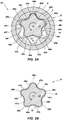
- FIG. 2A is a cross-sectional view of the stator 6 and the rotor 11 of the hydraulic drilling motor 10 taken at section A-A of FIG. 1A .
- FIG. 2B is a cross-sectional view of the rotor 11 of the hydraulic drilling motor 10 taken at section line A-A of FIG. 1A .
- the inner surface of the metal housing 4 and the outer surface of the resilient material 5 may each be approximately cylindrical or tubular.
- the inner surface 8 of the stator 6 shown in FIG. 2A includes lobes 42a-42f, which may be configured to interface with lobes 48a-48e of the rotor 11.
- the lobes 48a-48e of the rotor 11 move into and out of the spaces between the lobes 42a-42f of the stator 6.
- the stator 6 includes a resilient material 5
- the resilient material 5 may be designed to partially deform as the rotor 11 rotates.
- the resilient material 14 may be designed to partially deform as the rotor 11 rotates.
- the resilient materials 5, 14 may sustain a finite amount of damage (e.g., fatigue) for each rotation of the rotor 11.
- any damage to the resilient materials 5, 14 may be concentrated at portions of the resilient materials 5, 14 subjected to highest loads, which damage may be aggravated by solids in the drilling fluid.
- forces on the resilient material 5 may be concentrated on surfaces 44a-44f of the lobes 42a-42f.
- the surfaces 46a-46f on opposite sides of the lobes 42a-42f from the surfaces 44a-44f may be exposed to relatively lower stress.
- the portions of the lobes 42a-42f nearest the surfaces 44a-44f may sustain more damage than the portions of the lobes 42a-42f nearest the surfaces 46a-46f.
- FIG. 3 is a cross-sectional view of the stator 6 of the hydraulic drilling motor 10 taken at section line A-A of FIG. 1A after the stator 6 has been reversed from the orientation shown in FIG. 2A .
- the lobes 48a-48e of the rotor 11 move into and out of the spaces between the lobes 42a-42f of the stator 6 in the opposite order from the order corresponding to the orientation shown in FIG. 2A .
- the lobes 42a-42f may be symmetric, such that when the stator 6 is inverted, the lobes 42a-42f of the stator 6 engage with the lobes 48a-48e of the rotor 11 in the same manner as in the original non-inverted orientation.
- each of the surfaces 44a-44f and the surfaces 46a-46f may have identical profiles.
- FIG. 4 is a cross-sectional view of the rotor 11 of the hydraulic drilling motor 10 taken at section line A-A of FIG. 1A after the rotor 11 has been reversed from the orientation shown in FIG. 2B .
- the reversal may be independent of the reversal of the stator 6 depicted by the orientation shown in FIG. 3 .
- forces on the resilient material 14 may be concentrated on surfaces 47a-47e of the lobes 48a-48e.
- the surfaces 49a-49e on opposite sides of the lobes 48a-48e from the surfaces 47a-47e may be exposed to relatively lower stress.
- the portions of the lobes 48a-48e nearest the surfaces 47a-47e may sustain more damage than the portions of the lobes 48a-48e nearest the surfaces 49a-49e.
- the lobes 48a-48e may be symmetric, such that when the rotor 11 is inverted, the lobes 48a-48e of the stator 6 engage with the lobes 42a-42f of the stator 6 in the same manner as in the original non-inverted orientation.
- each of the surfaces 47a-47e and the surfaces 49a-49e may have identical profiles.
- the rotor 11 may have identical fittings at both ends.
- one or more adapters may be used to connect the rotor 11 to other parts of the hydraulic drilling motor 10.
- the more-worn or more-damaged portions of the resilient materials 5, 14 may be placed in positions where they are likely to be exposed to relatively lower stress, and the less-worn or less-damaged portions of the resilient materials 5, 14 may be placed in positions where they are likely to be exposed to relatively higher stress.
- the stator 6 and/or the rotor 11 may exhibit a longer useful life, and the stator 6 and/or the rotor 11 may wear more evenly than conventional stators and rotors.
- the stator 6 and/or the rotor 11 may exhibit approximately the same useful life in its second (reversed) orientation as in its first orientation. In such embodiments, the total life of the stator 6 and/or the rotor 11 may be approximately double the life of a conventional stator or rotor having similar materials and dimensions.
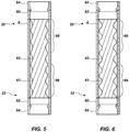
- FIG. 5 is another cross-sectional view illustrating the stator 6 of the hydraulic drilling motor 10.
- the stator 6 may include a first fitting 60 at one end of the stator 6 and a second fitting 62 at the opposite end of the stator 6.
- the first fitting 60 and the second fitting 62 may have identical threads ( e.g., the same pitch, thread density, and thread profile, both male or both female, etc. ), such that either the first fitting 60 or the second fitting 62 may be attached to top 30 or the bottom 32 of the power section 1 of the hydraulic drilling motor 10 (see FIG. 1A ).
- the first fitting 60 and/or the second fitting 62 may include one or more adapters 64 to connect the stator 6 to the top 30 or the bottom 32 of the power section 1.
- the first fitting 60 and the second fitting 62 need not have identical threads, although they may have identical threads, but the adapter(s) 64 may include appropriate threads to allow attachment to the top 30 or the bottom 32 of the power section 1.
- the adapter(s) 64 may, respectively, include an industry-standard box connection or pin connection.
- the stator 6 may include a more-worn region 66 near the lower end of the stator 6 and a less-worn region 68 near the upper end of the stator 6.
- the stator 6 may be reversed, such that the first fitting 60 is connected to the bottom 32 of the power section 1, and the second fitting 62 is connected to the top 30 of the power section 1.
- the more-worn region 66 is near the upper end of the stator 6 and a less-worn region 68 is near the lower end of the stator 6.
- the less-worn region 68 may be exposed to relatively more stress than the more-worn region 66 when the stator 6 is operated in this orientation.
- both regions 66, 68 may have similar amounts of wear or damage.
- the stator 6 and/or the rotor 11 may be free of the resilient materials 5, 14. If both the stator 6 and the rotor are free of the resilient materials 5, 14, the hydraulic drilling motor 10 may be referred to as a "metal-to-metal motor" because metal of the stator 6 contacts metal of the rotor 11 when the hydraulic drilling motor 10 is in operation. Metal-to-metal motors may be beneficial in some applications, such as when the hydraulic drilling motor 10 operates at temperatures above which the resilient materials 5, 14 are stable.
- the stators 6 and rotors 11 disclosed herein may be used in metal-to-metal motors to increase the useful life of such motors.
- FIG. 7 illustrates a cross-sectional view of another stator 6'.
- the stator 6' includes a metal housing 4' and a resilient material 5'.
- the inner surface of the metal housing 4 and the outer surface of the resilient material 5 may each be shaped to approximately correspond to the shape of the inner surface 8 of the stator 6', which may be the same shape as the inner surface 8 of the stator 6 shown in FIG. 2A . That is, the thickness of the resilient material 5' may be approximately uniform, and the shape of the inner surface 8 may be based on the shape of the inner surface of the metal housing 4'.
- the stator 6' may be referred to as "pre-contoured" because the shape of the inner surface 8 of the stator 6' is defined before application of the resilient material 5'.
- the stator 6' may be used in either direction in a hydraulic drilling motor 10 ( FIG. 1A ), as described above with respect to the stator 6 in reference to FIGS. 2A and 3 . That is, when the rotor 11 rotates in the direction indicated by arrow 15, forces on the resilient material 5' may be concentrated on surfaces 44a-44f of the lobes 42a-42f. The surfaces 46a-46f opposite the surfaces 44a-44f may be exposed to relatively little stress.
- the portions of the lobes 42a-42f nearest the surfaces 44a-44f may sustain more damage than the portions of the lobes 42a-42f nearest the surfaces 46a-46f.
- the portions of the lobes 42a-42f nearest the surfaces 46a-46f may sustain little to no significant damage when the stator 6' is used in the orientation of FIG. 7 .
- the stator 6' may be reversed ( e.g., inverted by flipping end-to-end).
- the rotor 11 rotates, different portions of the stator 6' experience relatively higher stresses from the portions experiencing relatively higher stresses in the orientation shown in FIG. 7 .
- forces on the resilient material 5' may be concentrated on surfaces 46a-46f of the lobes 42a-42f.
- the surfaces 44a-44f opposite the surfaces 46a-46f may be exposed to relatively lower stress at this time.
- the portions of the lobes 42a-42f nearest the surfaces 46a-46f may sustain more damage than the portions of the lobes 42a-42f nearest the surfaces 44a-44f.
- the wear on the resilient material 5' may be approximately the same near the surfaces 44a-44f and the surfaces 46a-46f. Reversal of the stator 6' may enable the stator 6' to have a longer useful life.
- the stator 6' when configured as described, may have lower risk of failure in service, such as by cracking and separation of the resilient material 5' while the stator 6' is downhole. Thus, the stator 6' may be reversibly used to limit non-productive time and tool damage.
- FIG. 8 illustrates a cross-sectional view of another stator 6".
- the stator 6" includes a metal housing 4" and a cartridge 80.
- the cartridge 80 includes a metal shell 82 and a resilient material 5" secured to the metal shell 82.
- the resilient material 5" may be bonded to the metal shell 82 by physical or chemical means. For example, an adhesive may be disposed between the resilient material 5" and the metal shell 82.
- the resilient material 5" may be structured and shaped such that the resilient material 5" stays in place within the metal shell 82.
- the cartridge 80 may include a mechanism for attachment in the metal housing 4", such as one or more tabs 84.
- the tabs 84 may protrude from the metal shell 82, and, when the cartridge 80 is placed within the metal housing 4", may be disposed within one or more corresponding slots 86 in the metal housing 4".
- rotation of the cartridge 80 within the metal housing 4" may be restricted by the interference of the tabs 84 with the metal housing 4".
- the cartridge 80 may be removable from the metal housing 4" so that the cartridge 80 may be operated in either of two opposing orientations, as previously described herein.
- the cartridge 80 may be configured to slide into and out of the metal housing 4" when the stator 6" is at least partially disconnected from a drill string. For example, when the stator 6" is separated from a bearing assembly 2 ( FIG. 1B ), the cartridge 80 may slide out of the metal housing 4" around the rotor 11.
- the cartridge 80 may include pins or other fastening means to lock the cartridge 80 inside the metal housing 4".
- a stator 6" having a cartridge 80 need not have the same connection hardware (e.g., threads, adapters, etc. ) at both ends thereof because the cartridge 80 itself can be reversed within the metal housing 4".
- connection hardware e.g., threads, adapters, etc.
- a stator 6" having a cartridge 80 may be fitted to existing drill strings with little modification, and without adapters.
- FIG. 9 illustrates a cross-sectional view of another rotor 11'.
- the rotor 11' includes a metal core 13' and a resilient material 14'.
- the outer surface of the metal core 13' may be circular, and the outer surface of the resilient material 14' may have lobes 48a-48e.
- the thickness of the resilient material 14' may be nonuniform.
- the rotor 11' may be used in either direction in a hydraulic drilling motor 10 ( FIG. 1A ), as described above with respect to the rotor 11 in reference to FIGS. 2B and 4 .
- FIG. 10 illustrates a cross-sectional view of another rotor 11".
- the rotor 11" includes a metal core 13" and a cartridge 90 over the metal core 13".
- the cartridge 90 includes a metal shell 92 and a resilient material 14" secured to the metal shell 92.
- the resilient material 14" may be bonded to the metal shell 92 by physical or chemical means. For example, an adhesive may be disposed between the resilient material 14" and the metal shell 92.
- the resilient material 14" may be structured and shaped such that the resilient material 14" stays in place over the metal shell 92.
- the cartridge 90 may include a mechanism for attachment to the metal core 13", such as one or more tabs 94.
- the tabs 94 may protrude from a surface of the metal shell 92, and, when the cartridge 90 is placed over the metal core 13", may be disposed within one or more corresponding slots 96 in the metal core 13". Thus, when the cartridge 90 is over the metal core 13", rotation of the cartridge 90 with respect to the metal core 13" may be restricted by the interference of the tabs 94 with the metal core 13".
- the cartridge 90 may be removable from the metal core 13" so that the cartridge 90 may be operated in either of two opposing orientations, as previously described herein.
- the cartridge 90 may be configured to slide onto and off of the metal core 13" when the rotor 11" is at least partially disconnected from a drill string. For example, when the rotor 11" is separated from a stator 6 ( FIG. 1A ), the cartridge 90 may slide off of the metal core 13".
- the cartridge 90 may include pins or other fastening means to lock the cartridge 90 to the metal core 13".
- a rotor 11" having a cartridge 90 need not have the same connection hardware (e.g., threads, adapters, etc. ) at both ends thereof because the cartridge 90 itself can be reversed over the metal core 13".
- connection hardware e.g., threads, adapters, etc.
- a rotor 11" having a cartridge 90 may be fitted to existing drill strings with little modification, and without adapters.
Landscapes
- Engineering & Computer Science (AREA)
- Life Sciences & Earth Sciences (AREA)
- Geology (AREA)
- Mining & Mineral Resources (AREA)
- Mechanical Engineering (AREA)
- Physics & Mathematics (AREA)
- Environmental & Geological Engineering (AREA)
- Fluid Mechanics (AREA)
- General Life Sciences & Earth Sciences (AREA)
- Geochemistry & Mineralogy (AREA)
- Hydraulic Motors (AREA)
- Rotary Pumps (AREA)
Claims (20)
- Hydraulisches Werkzeug (10), umfassend:einen Stator (6, 6', 6"); undeinen Rotor (11, 11', 11"), der innerhalb des Stators (6, 6', 6") drehbar angeordnet ist;wobei mindestens einer aus mindestens einem inneren Abschnitt des Stators (6, 6', 6") und mindestens einem äußeren Abschnitt des Rotors (11, 11', 11") konfiguriert ist, um in einen Bohrstrang in einer von zwei umgekehrten Ausrichtungen entlang einer Längsachse des hydraulischen Werkzeugs eingebaut zu werden; undwobei der Rotor (11, 11', 11") konfiguriert ist, um sich innerhalb des Stators (6, 6', 6") in einer der zwei umgekehrten Ausrichtungen zu drehen.
- Hydraulisches Werkzeug nach Anspruch 1, wobei der mindestens eine aus mindestens einem inneren Abschnitt des Stators (6, 6', 6") und dem mindestens einen äußeren Abschnitt des Rotors (11, 11', 11") ein elastisches Material (5, 5', 5"; 14, 14', 14") umfasst.
- Hydraulisches Werkzeug nach Anspruch 2, wobei das elastische Material (5, 5', 5"; 14, 14', 14") ein Material umfasst, das aus der Gruppe ausgewählt ist, die aus Fluorsilikonkautschuk, Acrylnitril-Butadien-Kautschuk, Fuorelastomeren, hydriertem Acrylnitril-Butadien-Kautschuk, fluoriertem Ethylenpropylen, Vinylmethylpolysiloxan, carboxyliertem Acrylnitril-Butadien-Kautschuk, Polyacrylat-Acrylkautschuk, Perfluorelastomeren, Ethylenpropylenkautschuk, Ethylen-Propylen-Dien-Monomer-Kautschuk und Acryl-Ethylen-Copolymer besteht.
- Hydraulisches Werkzeug nach Anspruch 2, wobei der mindestens eine innere Abschnitt des Stators (6, 6', 6") einen Einsatz umfasst, der das elastische Material (5") innerhalb einer Patrone (80) umfasst.
- Hydraulisches Werkzeug nach Anspruch 2, wobei der mindestens eine äußere Abschnitt des Rotors (11, 11', 11") eine Abdeckung umfasst, die das elastische Material (14, 14', 14") umfasst.
- Hydraulisches Werkzeug nach Anspruch 5, wobei die Abdeckung so konfiguriert ist, dass sie über dem Rotor (11, 11', 11") in einer von zwei umgekehrten Ausrichtungen entlang einer Längsachse des Rotors (11, 11', 11") angeordnet werden kann.
- Hydraulisches Werkzeug nach einem der Ansprüche 1 bis 6, wobei mindestens einer aus dem Stator (6, 6', 6") und dem Rotor (11, 11', 11") Folgendes umfasst:einen ersten Satz von Gewinden an einem ersten Ende davon; undeinen zweiten Satz von Gewinden an einem zweiten Ende davon, das dem ersten Ende gegenüberliegt;wobei der erste Satz von Gewinden und der zweite Satz von Gewinden jeweils konfiguriert sind, um an Adaptern (64), die entsprechende Anschlussstücke (60, 62) aufweisen, fixiert zu werden.
- Hydraulisches Werkzeug nach Anspruch 7, wobei der erste Satz von Gewinden eine Steigung, eine Gewindedichte und ein Gewindeprofil aufweist, die mit einer Steigung, einer Gewindedichte und einem Gewindeprofil des zweiten Satzes von Gewinden identisch sind.
- Hydraulisches Werkzeug nach Anspruch 7, wobei der erste Satz von Gewinden und der zweite Satz von Gewinden entweder beide Außengewinde oder beide Innengewinde sind.
- Hydraulisches Werkzeug nach einem der Ansprüche 1 bis 6, weiter umfassend mindestens einen Adapter (64), der an mindestens einem Ende des Stators (6, 6', 6") fixiert ist.
- Hydraulisches Werkzeug nach einem der Ansprüche 1 bis 6, wobei der Stator (6, 6', 6") ein Außengehäuse (4, 4', 4") und eine herausnehmbare Patrone (80) innerhalb des Außengehäuses (4, 4', 4") umfasst.
- Hydraulisches Werkzeug nach Anspruch 11, wobei die herausnehmbare Patrone (80) einen Metallmantel und eine Auskleidung umfasst, die ein elastisches Material (5, 5', 5") umfasst.
- Hydraulisches Werkzeug nach Anspruch 12, wobei der Metallmantel und das Außengehäuse (4, 4', 4") fest ineinandergreifen.
- Hydraulisches Werkzeug nach einem der Ansprüche 1 bis 6, weiter umfassend ein Hartauftragsschweißmaterial, das an mindestens einem aus einer Außenfläche des Rotors (11, 11', 11") und einer Innenfläche des Stators (6, 6', 6") aufgebracht ist, wobei das Hartauftragsschweißmaterial ein Material umfasst, das aus der Gruppe ausgewählt ist, die aus Chrom, Nickel, Kobalt, Wolframcarbid, Diamant, diamantähnlichem Kohlenstoff, Borcarbid, kubischem Bornitrid, Nitriden, Carbiden, Oxiden, Boriden und Legierungen, die durch Nitrieren, Borieren oder Karbonisieren gehärtet sind, besteht.
- Verfahren zur Verwendung eines hydraulischen Werkzeugs (10), umfassend:Anordnen eines Rotors (11, 11', 11") innerhalb eines Hohlraums, der von einem Stator (6, 6', 6") definiert wird, wobei der Stator (6, 6', 6") eine Vielzahl von Flügeln (42a-42f) aufweist, die ein erstes Ende nahe einem oberen Ende des hydraulischen Werkzeugs (10) und ein zweites Ende längs gegenüber dem ersten Ende nahe einem unteren Ende des hydraulischen Werkzeugs (10) aufweisen, wobei der Rotor (11, 11', 11") mindestens einen Flügel (48a-48e) aufweist, der ein erstes Ende und ein zweites Ende längs gegenüber dem ersten Ende aufweist, wobei das erste Ende des mindestens einen Flügels (48a-48e) des Rotors (11, 11', 11 ") nahe dem oberen Ende des hydraulischen Werkzeugs (10) angeordnet ist und wobei das zweite Ende des mindestens einen Flügels (48a-48e) des Rotors (11, 11', 11") nahe dem unteren Ende des hydraulischen Werkzeugs (10) angeordnet ist;Durchleiten eines Fluids durch den Hohlraum, der vom Stator (6, 6', 6") definiert wird, um den Rotor (11, 11', 11") zu drehen;mindestens eines aus dem Entfernen des Rotors (11, 11', 11") aus dem Hohlraum, der vom Stator (6, 6', 6") definiert wird, und dem Entfernen des Stators (6, 6', 6") aus dem hydraulischen Werkzeug (10); undmindestens eines aus:Anordnen des Rotors (11, 11', 11") in dem Hohlraum, der vom Stator (6, 6', 6") definiert wird, so dass das erste Ende des Rotors (11, 11', 11") nahe dem unteren Ende des hydraulischen Werkzeugs (10) angeordnet ist und das zweite Ende des Rotors (11, 11', 11") nahe dem oberen Ende des hydraulischen Werkzeugs (10) angeordnet ist; undFixieren des Stators (6, 6', 6") am hydraulischen Werkzeug (10), so dass das erste Ende des Stators (6, 6', 6") nahe dem unteren Ende des hydraulischen Werkzeugs (10) ist und das zweite Ende des Stators (6, 6', 6") nahe dem oberen Ende des hydraulischen Werkzeugs (10) ist.
- Verfahren nach Anspruch 15, weiter umfassend:Trennen einer Patrone (80), die die Vielzahl von Flügeln umfasst, von einem Außengehäuse (4, 4', 4") des Stators (6, 6', 6");Umkehren einer Längsausrichtung der Patrone (80) in Bezug auf das Außengehäuse (4, 4', 4"); undEinsetzen der Patrone (80) in das Außengehäuse (4, 4', 4") in der umgekehrten Längsausrichtung.
- Verfahren nach Anspruch 15, weiter umfassend das Fixieren eines Adapters (64) an mindestens einem Ende des Stators (6, 6', 6") .
- Verfahren nach Anspruch 15, weiter umfassend das Befestigen des Rotors (11, 11', 11") an einer Antriebswelle (52), die konfiguriert ist, um einen Bohrereinsatz zu drehen.
- Verfahren nach Anspruch 15, wobei das Anordnen des Rotors (11, 11', 11") in dem Hohlraum, der vom Stator (6, 6', 6") definiert wird, so dass das erste Ende des Rotors (11, 11', 11") nahe dem zweiten Ende des Stators (6, 6', 6") angeordnet ist und das zweite Ende des Rotors (11, 11', 11") nahe dem ersten Ende des Stators (6, 6', 6") angeordnet ist, das Umkehren einer Richtung des Stators (6, 6', 6") in einem Bohrstrang umfasst.
- Bohrsystem, umfassend das hydraulische Werkzeug (10) nach einem der Ansprüche 1 bis 6 und weiter umfassend:eine Fluidquelle;eine Antriebswelle (52), die in Wirkverbindung mit dem Rotor (11, 11', 11 ") des hydraulischen Werkzeugs (10) steht;undeinen Bohrereinsatz, der in Wirkverbindung mit der Antriebswelle (52) steht.
Applications Claiming Priority (2)
| Application Number | Priority Date | Filing Date | Title |
|---|---|---|---|
| US14/071,876 US20150122549A1 (en) | 2013-11-05 | 2013-11-05 | Hydraulic tools, drilling systems including hydraulic tools, and methods of using hydraulic tools |
| PCT/US2014/063807 WO2015069618A1 (en) | 2013-11-05 | 2014-11-04 | Hydraulic tools, drilling systems including hydraulic tools, and methods of using hydraulic tools |
Publications (3)
| Publication Number | Publication Date |
|---|---|
| EP3066287A1 EP3066287A1 (de) | 2016-09-14 |
| EP3066287A4 EP3066287A4 (de) | 2017-07-05 |
| EP3066287B1 true EP3066287B1 (de) | 2018-12-26 |
Family
ID=53006163
Family Applications (1)
| Application Number | Title | Priority Date | Filing Date |
|---|---|---|---|
| EP14859966.5A Active EP3066287B1 (de) | 2013-11-05 | 2014-11-04 | Hydraulische werkzeuge, bohrsysteme mit hydraulischen werkzeugen und verfahren zur verwendung hydraulischer werkzeuge |
Country Status (3)
| Country | Link |
|---|---|
| US (4) | US20150122549A1 (de) |
| EP (1) | EP3066287B1 (de) |
| WO (1) | WO2015069618A1 (de) |
Families Citing this family (11)
| Publication number | Priority date | Publication date | Assignee | Title |
|---|---|---|---|---|
| US20150122549A1 (en) * | 2013-11-05 | 2015-05-07 | Baker Hughes Incorporated | Hydraulic tools, drilling systems including hydraulic tools, and methods of using hydraulic tools |
| WO2016093857A1 (en) * | 2014-12-12 | 2016-06-16 | Halliburton Energy Services, Inc. | Drilling tool bearing and drivetrain assembly |
| US9896885B2 (en) | 2015-12-10 | 2018-02-20 | Baker Hughes Incorporated | Hydraulic tools including removable coatings, drilling systems, and methods of making and using hydraulic tools |
| CN106426830B (zh) * | 2016-09-23 | 2020-02-18 | 华南理工大学 | 一种利用偏心转子偏载驱动的动态混合方法及装置 |
| CA2961629A1 (en) | 2017-03-22 | 2018-09-22 | Infocus Energy Services Inc. | Reaming systems, devices, assemblies, and related methods of use |
| CN110005336A (zh) * | 2019-04-09 | 2019-07-12 | 盐城华亚石油机械制造有限公司 | 一种煤层气专用耐磨高效螺杆钻具及加工工艺 |
| US11795946B2 (en) * | 2020-03-04 | 2023-10-24 | Schlumberger Technology Corporation | Mud motor rotor with core and shell |
| WO2022006240A1 (en) | 2020-06-30 | 2022-01-06 | Schlumberger Technology Corporation | Over mandrel extrusion for composite pcp stator |
| EP4587682A4 (de) * | 2022-10-12 | 2025-08-06 | Services Petroliers Schlumberger | Pumpenstatorbindeschicht |
| US20250020025A1 (en) * | 2023-07-11 | 2025-01-16 | Thru Tubing Solutions, Inc. | Positive displacement fluid motor and associated method |
| US20260062999A1 (en) * | 2024-08-28 | 2026-03-05 | Thru Tubing Solutions, Inc. | Downhole fluid motor and associated methods |
Family Cites Families (94)
| Publication number | Priority date | Publication date | Assignee | Title |
|---|---|---|---|---|
| US3084631A (en) * | 1962-01-17 | 1963-04-09 | Robbins & Myers | Helical gear pump with stator compression |
| US3499389A (en) * | 1967-04-19 | 1970-03-10 | Seeberger Kg | Worm pump |
| US3802803A (en) * | 1971-10-13 | 1974-04-09 | A Bogdanov | Submersible screw pump |
| US3975120A (en) * | 1973-11-14 | 1976-08-17 | Smith International, Inc. | Wafer elements for progressing cavity stators |
| US3975121A (en) * | 1973-11-14 | 1976-08-17 | Smith International, Inc. | Wafer elements for progressing cavity stators |
| US3982858A (en) * | 1973-11-14 | 1976-09-28 | Smith International Corporation, Inc. | Segmented stator for progressive cavity transducer |
| US3999901A (en) * | 1973-11-14 | 1976-12-28 | Smith International, Inc. | Progressive cavity transducer |
| US3912426A (en) * | 1974-01-15 | 1975-10-14 | Smith International | Segmented stator for progressive cavity transducer |
| US4144001A (en) * | 1977-03-29 | 1979-03-13 | Fordertechnik Streicher Gmbh | Eccentric worm pump with annular wearing elements |
| US4207037A (en) * | 1978-07-17 | 1980-06-10 | Eastman Whipstock, Inc. | Stator for a downhole fluid operated motor and method of assembling the same |
| US4271915A (en) * | 1979-08-06 | 1981-06-09 | Bodine Albert G | Elastically vibratory longitudinal jacketed drill |
| US4585401A (en) * | 1984-02-09 | 1986-04-29 | Veesojuzny Ordena Trudovogo Krasnogo Znameni Naucho-Issle | Multistage helical down-hole machine with frictional coupling of working elements, and method therefor |
| US5150509A (en) * | 1984-05-03 | 1992-09-29 | Kompan A/S | Method of producing a stabilized bolt joint between a timber element and another construction element and the timber construction |
| SU1192432A1 (ru) * | 1984-07-19 | 1989-07-07 | Inst Burovoi Tekhnik | Mohtaжhoe пpиcпocoблehиe для opиehtиpobahhoй cбopkи paбoчиx opгahob bиhtoboгo зaбoйhoгo дbигateля, cпocoб eгo hactpoйkи и cпocoб opиehtиpobahhoй cбopkи paбoчиx opгahob bиhtoboгo зaбoйhoгo дbигateля |
| US4636151A (en) * | 1985-03-13 | 1987-01-13 | Hughes Tool Company | Downhole progressive cavity type drilling motor with flexible connecting rod |
| ATE75521T1 (de) * | 1986-01-31 | 1992-05-15 | Perm Vnii Burovoj Tekhn | Rotor eines bohrlochschneckenmotors und dessen herstellung. |
| US6183226B1 (en) * | 1986-04-24 | 2001-02-06 | Steven M. Wood | Progressive cavity motors using composite materials |
| US4669555A (en) * | 1986-04-28 | 1987-06-02 | Conoco Inc. | Downhole circulation pump |
| CH677518A5 (de) * | 1988-09-30 | 1991-05-31 | Gd Anker Gmbh & Co Kg | |
| US5171138A (en) * | 1990-12-20 | 1992-12-15 | Drilex Systems, Inc. | Composite stator construction for downhole drilling motors |
| US5620056A (en) * | 1995-06-07 | 1997-04-15 | Halliburton Company | Coupling for a downhole tandem drilling motor |
| US5832604A (en) * | 1995-09-08 | 1998-11-10 | Hydro-Drill, Inc. | Method of manufacturing segmented stators for helical gear pumps and motors |
| US5769618A (en) * | 1995-09-25 | 1998-06-23 | Heishin Sobi Kabushiki Kaisha | Uniaxial eccentric screw pump having a flexible plastic shaft |
| US6461128B2 (en) * | 1996-04-24 | 2002-10-08 | Steven M. Wood | Progressive cavity helical device |
| US5807087A (en) * | 1997-03-21 | 1998-09-15 | Tarby, Inc. | Stator assembly for a progressing cavity pump |
| DE69818099T2 (de) * | 1997-12-18 | 2004-03-25 | Baker-Hughes Inc., Houston | Verfahren zur herstellung von statormanteln für exzenterschneckenpumpen |
| DE19827101A1 (de) * | 1998-06-18 | 1999-12-23 | Artemis Kautschuk Kunststoff | Nach dem Moineau-Prinzip arbeitende Maschine für den Einsatz in Tiefbohrungen |
| GB9816607D0 (en) * | 1998-07-31 | 1998-09-30 | Drentham Susman Hector F A Van | Turbine |
| US6170572B1 (en) * | 1999-05-25 | 2001-01-09 | Delaware Capital Formation, Inc. | Progressing cavity pump production tubing having permanent rotor bearings/core centering bearings |
| US20020074167A1 (en) * | 2000-12-20 | 2002-06-20 | Andrei Plop | High speed positive displacement motor |
| US6568485B2 (en) | 2001-04-17 | 2003-05-27 | Thomas E. Falgout, Sr. | Stalled motor by-pass valve |
| US6604922B1 (en) | 2002-03-14 | 2003-08-12 | Schlumberger Technology Corporation | Optimized fiber reinforced liner material for positive displacement drilling motors |
| US7442019B2 (en) * | 2002-10-21 | 2008-10-28 | Noetic Engineering Inc. | Stator of a moineau-pump |
| US7084782B2 (en) * | 2002-12-23 | 2006-08-01 | Halliburton Energy Services, Inc. | Drill string telemetry system and method |
| US6881045B2 (en) * | 2003-06-19 | 2005-04-19 | Robbins & Myers Energy Systems, L.P. | Progressive cavity pump/motor |
| US7192260B2 (en) * | 2003-10-09 | 2007-03-20 | Lehr Precision, Inc. | Progressive cavity pump/motor stator, and apparatus and method to manufacture same by electrochemical machining |
| CA2543554C (en) * | 2003-10-27 | 2010-03-09 | Dyna-Drill Technologies, Inc. | Asymmetric contouring of elastomer liner on lobes in a moineau style power section stator |
| US20060131079A1 (en) * | 2004-12-16 | 2006-06-22 | Halliburton Energy Services, Inc. | Composite motor stator |
| US7396220B2 (en) * | 2005-02-11 | 2008-07-08 | Dyna-Drill Technologies, Inc. | Progressing cavity stator including at least one cast longitudinal section |
| GB2424452B (en) * | 2005-03-22 | 2011-01-19 | Schlumberger Holdings | Progressive cavity motor with rotor having an elastomer sleeve |
| US20080000083A1 (en) * | 2005-04-08 | 2008-01-03 | Wood Steven M | Process for lining a fluid helical device stator |
| DE102005028818B3 (de) * | 2005-06-22 | 2006-08-24 | Artemis Kautschuk- Und Kunststoff-Technik Gmbh | Stator für eine Exzenterschneckenpumpe und Verfahren zu seiner Herstellung |
| US8337182B2 (en) * | 2006-10-03 | 2012-12-25 | Schlumberger Technology Corporation | Skinning of progressive cavity apparatus |
| US9051780B2 (en) * | 2007-01-09 | 2015-06-09 | Schlumberger Technology Corporation | Progressive cavity hydraulic machine |
| NO327505B1 (no) * | 2007-09-11 | 2009-07-27 | Agr Subsea As | Eksenterskruepumpe tilpasset pumping av kompressible fluider |
| NO327503B1 (no) * | 2007-09-20 | 2009-07-27 | Agr Subsea As | Eksenterskruepumpe med flere pumpeseksjoner |
| US7757781B2 (en) * | 2007-10-12 | 2010-07-20 | Halliburton Energy Services, Inc. | Downhole motor assembly and method for torque regulation |
| US8215014B2 (en) * | 2007-10-31 | 2012-07-10 | Moyno, Inc. | Method for making a stator |
| GB2454700B (en) | 2007-11-15 | 2013-05-15 | Schlumberger Holdings | Work extraction from downhole progressive cavity devices |
| CA2612326C (en) * | 2007-11-27 | 2011-06-14 | Kudu Industries Inc. | Progressing cavity pump assembly and method of operation |
| US20100038142A1 (en) * | 2007-12-18 | 2010-02-18 | Halliburton Energy Services, Inc. | Apparatus and method for high temperature drilling operations |
| US7941906B2 (en) * | 2007-12-31 | 2011-05-17 | Schlumberger Technology Corporation | Progressive cavity apparatus with transducer and methods of forming and use |
| US20100006342A1 (en) * | 2008-07-11 | 2010-01-14 | Baker Hughes Incorporated | Method of making wellbore moineau devices |
| NO329714B1 (no) * | 2008-08-21 | 2010-12-06 | Agr Subsea As | Ytre rotor i eksenterskruepumpe med en indre og en ytre rotor |
| GB0904055D0 (en) | 2009-03-10 | 2009-04-22 | Russell Michael K | Hydraulic torque control system |
| WO2010141408A2 (en) * | 2009-06-01 | 2010-12-09 | National Oilwell Varco, L. P. | No-go tag systems and methods for progressive cavity pumps |
| US8109746B2 (en) * | 2009-06-12 | 2012-02-07 | Robbins & Myers Energy Systems L.P. | Progressing cavity pump/motor |
| US9347266B2 (en) * | 2009-11-13 | 2016-05-24 | Schlumberger Technology Corporation | Stator inserts, methods of fabricating the same, and downhole motors incorporating the same |
| US8777598B2 (en) * | 2009-11-13 | 2014-07-15 | Schlumberger Technology Corporation | Stators for downwhole motors, methods for fabricating the same, and downhole motors incorporating the same |
| NO346718B1 (no) * | 2010-07-23 | 2022-12-05 | Baker Hughes Holdings Llc | Komponenter og motorer for nedihullsverktøy og fremgangsmåte for å påføre hardsveising på overflatene derav |
| WO2012024215A2 (en) * | 2010-08-16 | 2012-02-23 | National Oilwell Varco, L.P. | Reinforced stators and fabrication methods |
| US9482223B2 (en) * | 2010-11-19 | 2016-11-01 | Smith International, Inc. | Apparatus and method for controlling or limiting rotor orbit in moving cavity motors and pumps |
| US8944789B2 (en) * | 2010-12-10 | 2015-02-03 | National Oilwell Varco, L.P. | Enhanced elastomeric stator insert via reinforcing agent distribution and orientation |
| EP2683906A4 (de) | 2011-03-08 | 2015-07-29 | Services Petroliers Schlumberger | Lager und getriebe für einen pdm-rotor/stator |
| US9909365B2 (en) * | 2011-04-29 | 2018-03-06 | Baker Hughes Incorporated | Downhole tools having mechanical joints with enhanced surfaces |
| US8776916B2 (en) * | 2011-07-01 | 2014-07-15 | Baker Hughes Incorporated | Drilling motors with elastically deformable lobes |
| US9340854B2 (en) * | 2011-07-13 | 2016-05-17 | Baker Hughes Incorporated | Downhole motor with diamond-like carbon coating on stator and/or rotor and method of making said downhole motor |
| US8800688B2 (en) * | 2011-07-20 | 2014-08-12 | Baker Hughes Incorporated | Downhole motors with a lubricating unit for lubricating the stator and rotor |
| US20130052067A1 (en) * | 2011-08-26 | 2013-02-28 | Baker Hughes Incorporated | Downhole Motors and Pumps with Improved Stators and Methods of Making and Using Same |
| US9540545B2 (en) * | 2011-09-02 | 2017-01-10 | Schlumberger Technology Corporation | Plasma treatment in fabricating directional drilling assemblies |
| US8888474B2 (en) * | 2011-09-08 | 2014-11-18 | Baker Hughes Incorporated | Downhole motors and pumps with asymmetric lobes |
| US9228584B2 (en) * | 2011-11-10 | 2016-01-05 | Schlumberger Technology Corporation | Reinforced directional drilling assemblies and methods of forming same |
| DE112012004811T5 (de) * | 2011-11-18 | 2014-07-31 | Smith International, Inc. | Verdrängungsmotor mit radial eingeschränktem Rotormitnehmer |
| US9091264B2 (en) * | 2011-11-29 | 2015-07-28 | Baker Hughes Incorporated | Apparatus and methods utilizing progressive cavity motors and pumps with rotors and/or stators with hybrid liners |
| US9127508B2 (en) * | 2012-01-10 | 2015-09-08 | Baker Hughes Incorporated | Apparatus and methods utilizing progressive cavity motors and pumps with independent stages |
| RU2014138063A (ru) * | 2012-02-21 | 2016-04-10 | Шлюмбергер Холдингз Лимитед | Волоконно-армированный эластомерный статор |
| US9404493B2 (en) * | 2012-06-04 | 2016-08-02 | Indian Institute Of Technology Madras | Progressive cavity pump including a bearing between the rotor and stator |
| WO2014014442A1 (en) * | 2012-07-16 | 2014-01-23 | Halliburton Energy Services, Inc. | Downhole motors having adjustable power units |
| CA2882736C (en) * | 2012-08-24 | 2021-10-26 | Barson Composites Corporation | Coatings for fluid energy device components |
| US8985977B2 (en) * | 2012-09-06 | 2015-03-24 | Baker Hughes Incorporated | Asymmetric lobes for motors and pumps |
| US9441627B2 (en) * | 2012-11-01 | 2016-09-13 | National Oilwell Varco, L.P. | Lightweight and flexible rotors for positive displacement devices |
| US8967985B2 (en) * | 2012-11-13 | 2015-03-03 | Roper Pump Company | Metal disk stacked stator with circular rigid support rings |
| CN104919175A (zh) * | 2012-12-19 | 2015-09-16 | 普拉德研究及开发股份有限公司 | 基于螺杆的控制系统 |
| US9217286B2 (en) * | 2012-12-21 | 2015-12-22 | Halliburton Energy Services, Inc. | Anti-reverse mechanism for mud motor |
| US9194208B2 (en) * | 2013-01-11 | 2015-11-24 | Thru Tubing Solutions, Inc. | Downhole vibratory apparatus |
| EP2973958A4 (de) * | 2013-03-13 | 2016-09-21 | Services Petroliers Schlumberger | Massiv verstärkter elastomerer stator |
| US9695637B2 (en) * | 2013-03-15 | 2017-07-04 | Smith International, Inc. | Downhole turbine motor and related assemblies |
| US9133841B2 (en) * | 2013-04-11 | 2015-09-15 | Cameron International Corporation | Progressing cavity stator with metal plates having apertures with englarged ends |
| US9856872B2 (en) * | 2013-05-23 | 2018-01-02 | Husky Oil Operations Limited | Progressive cavity pump and method for operating same in boreholes |
| US9112398B2 (en) * | 2013-06-25 | 2015-08-18 | Baker Hughes Incorporated | Nitrogen- and ceramic-surface-treated components for downhole motors and related methods |
| US20150122549A1 (en) * | 2013-11-05 | 2015-05-07 | Baker Hughes Incorporated | Hydraulic tools, drilling systems including hydraulic tools, and methods of using hydraulic tools |
| WO2015126955A2 (en) * | 2014-02-18 | 2015-08-27 | Reme Technologies, Llc | Graphene enhanced elastomeric stator |
| US20150267492A1 (en) * | 2014-03-18 | 2015-09-24 | Edwin J. Broussard, JR. | Top mount dual bit well drilling system |
| US9869126B2 (en) * | 2014-08-11 | 2018-01-16 | Nabors Drilling Technologies Usa, Inc. | Variable diameter stator and rotor for progressing cavity motor |
-
2013
- 2013-11-05 US US14/071,876 patent/US20150122549A1/en not_active Abandoned
-
2014
- 2014-11-04 EP EP14859966.5A patent/EP3066287B1/de active Active
- 2014-11-04 WO PCT/US2014/063807 patent/WO2015069618A1/en not_active Ceased
-
2017
- 2017-07-14 US US15/649,807 patent/US11261666B2/en active Active
-
2022
- 2022-01-19 US US17/648,386 patent/US11821288B2/en active Active
- 2022-08-25 US US17/822,341 patent/US11946341B2/en active Active
Non-Patent Citations (1)
| Title |
|---|
| None * |
Also Published As
| Publication number | Publication date |
|---|---|
| US20230003083A1 (en) | 2023-01-05 |
| US11261666B2 (en) | 2022-03-01 |
| US11821288B2 (en) | 2023-11-21 |
| EP3066287A1 (de) | 2016-09-14 |
| EP3066287A4 (de) | 2017-07-05 |
| US20220145706A1 (en) | 2022-05-12 |
| US11946341B2 (en) | 2024-04-02 |
| US20170306700A1 (en) | 2017-10-26 |
| US20150122549A1 (en) | 2015-05-07 |
| WO2015069618A1 (en) | 2015-05-14 |
Similar Documents
| Publication | Publication Date | Title |
|---|---|---|
| US11946341B2 (en) | Hydraulic tools, drilling systems including hydraulic tools, and methods of using hydraulic tools | |
| US10450800B2 (en) | Bearing/gearing section for a PDM rotor/stator | |
| RU2602856C2 (ru) | Двигатель объемного типа с радиально ограниченным зацеплением ротора | |
| CN103890304B (zh) | 带有非对称波瓣的井下马达和泵 | |
| US9051780B2 (en) | Progressive cavity hydraulic machine | |
| CN106030018B (zh) | 包括插入件的液压工具和相关方法 | |
| US8776916B2 (en) | Drilling motors with elastically deformable lobes | |
| EP3387207B1 (de) | Hydraulische werkzeuge mit entfernbaren beschichtungen, bohrsysteme und verfahren zur herstellung und verwendung hydraulischer werkzeuge | |
| GB2525500B (en) | Asymmetric lobes for motors and pumps | |
| WO2009139658A1 (en) | Progressive cavity hydraulic machine | |
| RU2285823C1 (ru) | Статор винтовой героторной гидромашины |
Legal Events
| Date | Code | Title | Description |
|---|---|---|---|
| PUAI | Public reference made under article 153(3) epc to a published international application that has entered the european phase |
Free format text: ORIGINAL CODE: 0009012 |
|
| 17P | Request for examination filed |
Effective date: 20160603 |
|
| AK | Designated contracting states |
Kind code of ref document: A1 Designated state(s): AL AT BE BG CH CY CZ DE DK EE ES FI FR GB GR HR HU IE IS IT LI LT LU LV MC MK MT NL NO PL PT RO RS SE SI SK SM TR |
|
| AX | Request for extension of the european patent |
Extension state: BA ME |
|
| DAX | Request for extension of the european patent (deleted) | ||
| A4 | Supplementary search report drawn up and despatched |
Effective date: 20170607 |
|
| RIC1 | Information provided on ipc code assigned before grant |
Ipc: F04D 13/10 20060101ALI20170531BHEP Ipc: E21B 4/02 20060101AFI20170531BHEP |
|
| STAA | Information on the status of an ep patent application or granted ep patent |
Free format text: STATUS: EXAMINATION IS IN PROGRESS |
|
| 17Q | First examination report despatched |
Effective date: 20171208 |
|
| GRAP | Despatch of communication of intention to grant a patent |
Free format text: ORIGINAL CODE: EPIDOSNIGR1 |
|
| STAA | Information on the status of an ep patent application or granted ep patent |
Free format text: STATUS: GRANT OF PATENT IS INTENDED |
|
| INTG | Intention to grant announced |
Effective date: 20180614 |
|
| RAP1 | Party data changed (applicant data changed or rights of an application transferred) |
Owner name: BAKER HUGHES, A GE COMPANY, LLC |
|
| GRAS | Grant fee paid |
Free format text: ORIGINAL CODE: EPIDOSNIGR3 |
|
| GRAA | (expected) grant |
Free format text: ORIGINAL CODE: 0009210 |
|
| STAA | Information on the status of an ep patent application or granted ep patent |
Free format text: STATUS: THE PATENT HAS BEEN GRANTED |
|
| AK | Designated contracting states |
Kind code of ref document: B1 Designated state(s): AL AT BE BG CH CY CZ DE DK EE ES FI FR GB GR HR HU IE IS IT LI LT LU LV MC MK MT NL NO PL PT RO RS SE SI SK SM TR |
|
| REG | Reference to a national code |
Ref country code: GB Ref legal event code: FG4D |
|
| REG | Reference to a national code |
Ref country code: CH Ref legal event code: EP |
|
| REG | Reference to a national code |
Ref country code: AT Ref legal event code: REF Ref document number: 1081660 Country of ref document: AT Kind code of ref document: T Effective date: 20190115 |
|
| REG | Reference to a national code |
Ref country code: DE Ref legal event code: R096 Ref document number: 602014038867 Country of ref document: DE |
|
| REG | Reference to a national code |
Ref country code: IE Ref legal event code: FG4D |
|
| REG | Reference to a national code |
Ref country code: NO Ref legal event code: T2 Effective date: 20181226 |
|
| PG25 | Lapsed in a contracting state [announced via postgrant information from national office to epo] |
Ref country code: LV Free format text: LAPSE BECAUSE OF FAILURE TO SUBMIT A TRANSLATION OF THE DESCRIPTION OR TO PAY THE FEE WITHIN THE PRESCRIBED TIME-LIMIT Effective date: 20181226 Ref country code: HR Free format text: LAPSE BECAUSE OF FAILURE TO SUBMIT A TRANSLATION OF THE DESCRIPTION OR TO PAY THE FEE WITHIN THE PRESCRIBED TIME-LIMIT Effective date: 20181226 Ref country code: BG Free format text: LAPSE BECAUSE OF FAILURE TO SUBMIT A TRANSLATION OF THE DESCRIPTION OR TO PAY THE FEE WITHIN THE PRESCRIBED TIME-LIMIT Effective date: 20190326 Ref country code: LT Free format text: LAPSE BECAUSE OF FAILURE TO SUBMIT A TRANSLATION OF THE DESCRIPTION OR TO PAY THE FEE WITHIN THE PRESCRIBED TIME-LIMIT Effective date: 20181226 Ref country code: FI Free format text: LAPSE BECAUSE OF FAILURE TO SUBMIT A TRANSLATION OF THE DESCRIPTION OR TO PAY THE FEE WITHIN THE PRESCRIBED TIME-LIMIT Effective date: 20181226 |
|
| REG | Reference to a national code |
Ref country code: NL Ref legal event code: MP Effective date: 20181226 |
|
| REG | Reference to a national code |
Ref country code: LT Ref legal event code: MG4D |
|
| PG25 | Lapsed in a contracting state [announced via postgrant information from national office to epo] |
Ref country code: SE Free format text: LAPSE BECAUSE OF FAILURE TO SUBMIT A TRANSLATION OF THE DESCRIPTION OR TO PAY THE FEE WITHIN THE PRESCRIBED TIME-LIMIT Effective date: 20181226 Ref country code: RS Free format text: LAPSE BECAUSE OF FAILURE TO SUBMIT A TRANSLATION OF THE DESCRIPTION OR TO PAY THE FEE WITHIN THE PRESCRIBED TIME-LIMIT Effective date: 20181226 Ref country code: GR Free format text: LAPSE BECAUSE OF FAILURE TO SUBMIT A TRANSLATION OF THE DESCRIPTION OR TO PAY THE FEE WITHIN THE PRESCRIBED TIME-LIMIT Effective date: 20190327 Ref country code: AL Free format text: LAPSE BECAUSE OF FAILURE TO SUBMIT A TRANSLATION OF THE DESCRIPTION OR TO PAY THE FEE WITHIN THE PRESCRIBED TIME-LIMIT Effective date: 20181226 |
|
| PG25 | Lapsed in a contracting state [announced via postgrant information from national office to epo] |
Ref country code: NL Free format text: LAPSE BECAUSE OF FAILURE TO SUBMIT A TRANSLATION OF THE DESCRIPTION OR TO PAY THE FEE WITHIN THE PRESCRIBED TIME-LIMIT Effective date: 20181226 |
|
| PG25 | Lapsed in a contracting state [announced via postgrant information from national office to epo] |
Ref country code: PT Free format text: LAPSE BECAUSE OF FAILURE TO SUBMIT A TRANSLATION OF THE DESCRIPTION OR TO PAY THE FEE WITHIN THE PRESCRIBED TIME-LIMIT Effective date: 20190426 Ref country code: ES Free format text: LAPSE BECAUSE OF FAILURE TO SUBMIT A TRANSLATION OF THE DESCRIPTION OR TO PAY THE FEE WITHIN THE PRESCRIBED TIME-LIMIT Effective date: 20181226 Ref country code: CZ Free format text: LAPSE BECAUSE OF FAILURE TO SUBMIT A TRANSLATION OF THE DESCRIPTION OR TO PAY THE FEE WITHIN THE PRESCRIBED TIME-LIMIT Effective date: 20181226 Ref country code: IT Free format text: LAPSE BECAUSE OF FAILURE TO SUBMIT A TRANSLATION OF THE DESCRIPTION OR TO PAY THE FEE WITHIN THE PRESCRIBED TIME-LIMIT Effective date: 20181226 Ref country code: PL Free format text: LAPSE BECAUSE OF FAILURE TO SUBMIT A TRANSLATION OF THE DESCRIPTION OR TO PAY THE FEE WITHIN THE PRESCRIBED TIME-LIMIT Effective date: 20181226 |
|
| PG25 | Lapsed in a contracting state [announced via postgrant information from national office to epo] |
Ref country code: SK Free format text: LAPSE BECAUSE OF FAILURE TO SUBMIT A TRANSLATION OF THE DESCRIPTION OR TO PAY THE FEE WITHIN THE PRESCRIBED TIME-LIMIT Effective date: 20181226 Ref country code: IS Free format text: LAPSE BECAUSE OF FAILURE TO SUBMIT A TRANSLATION OF THE DESCRIPTION OR TO PAY THE FEE WITHIN THE PRESCRIBED TIME-LIMIT Effective date: 20190426 Ref country code: EE Free format text: LAPSE BECAUSE OF FAILURE TO SUBMIT A TRANSLATION OF THE DESCRIPTION OR TO PAY THE FEE WITHIN THE PRESCRIBED TIME-LIMIT Effective date: 20181226 Ref country code: RO Free format text: LAPSE BECAUSE OF FAILURE TO SUBMIT A TRANSLATION OF THE DESCRIPTION OR TO PAY THE FEE WITHIN THE PRESCRIBED TIME-LIMIT Effective date: 20181226 Ref country code: SM Free format text: LAPSE BECAUSE OF FAILURE TO SUBMIT A TRANSLATION OF THE DESCRIPTION OR TO PAY THE FEE WITHIN THE PRESCRIBED TIME-LIMIT Effective date: 20181226 |
|
| REG | Reference to a national code |
Ref country code: DE Ref legal event code: R097 Ref document number: 602014038867 Country of ref document: DE |
|
| PG25 | Lapsed in a contracting state [announced via postgrant information from national office to epo] |
Ref country code: DK Free format text: LAPSE BECAUSE OF FAILURE TO SUBMIT A TRANSLATION OF THE DESCRIPTION OR TO PAY THE FEE WITHIN THE PRESCRIBED TIME-LIMIT Effective date: 20181226 |
|
| PLBE | No opposition filed within time limit |
Free format text: ORIGINAL CODE: 0009261 |
|
| STAA | Information on the status of an ep patent application or granted ep patent |
Free format text: STATUS: NO OPPOSITION FILED WITHIN TIME LIMIT |
|
| 26N | No opposition filed |
Effective date: 20190927 |
|
| PG25 | Lapsed in a contracting state [announced via postgrant information from national office to epo] |
Ref country code: SI Free format text: LAPSE BECAUSE OF FAILURE TO SUBMIT A TRANSLATION OF THE DESCRIPTION OR TO PAY THE FEE WITHIN THE PRESCRIBED TIME-LIMIT Effective date: 20181226 |
|
| PGFP | Annual fee paid to national office [announced via postgrant information from national office to epo] |
Ref country code: FR Payment date: 20191022 Year of fee payment: 6 |
|
| PG25 | Lapsed in a contracting state [announced via postgrant information from national office to epo] |
Ref country code: TR Free format text: LAPSE BECAUSE OF FAILURE TO SUBMIT A TRANSLATION OF THE DESCRIPTION OR TO PAY THE FEE WITHIN THE PRESCRIBED TIME-LIMIT Effective date: 20181226 |
|
| PGFP | Annual fee paid to national office [announced via postgrant information from national office to epo] |
Ref country code: AT Payment date: 20191023 Year of fee payment: 6 |
|
| REG | Reference to a national code |
Ref country code: CH Ref legal event code: PL |
|
| PG25 | Lapsed in a contracting state [announced via postgrant information from national office to epo] |
Ref country code: LU Free format text: LAPSE BECAUSE OF NON-PAYMENT OF DUE FEES Effective date: 20191104 Ref country code: MC Free format text: LAPSE BECAUSE OF FAILURE TO SUBMIT A TRANSLATION OF THE DESCRIPTION OR TO PAY THE FEE WITHIN THE PRESCRIBED TIME-LIMIT Effective date: 20181226 Ref country code: LI Free format text: LAPSE BECAUSE OF NON-PAYMENT OF DUE FEES Effective date: 20191130 Ref country code: CH Free format text: LAPSE BECAUSE OF NON-PAYMENT OF DUE FEES Effective date: 20191130 |
|
| REG | Reference to a national code |
Ref country code: BE Ref legal event code: MM Effective date: 20191130 |
|
| PG25 | Lapsed in a contracting state [announced via postgrant information from national office to epo] |
Ref country code: IE Free format text: LAPSE BECAUSE OF NON-PAYMENT OF DUE FEES Effective date: 20191104 |
|
| PG25 | Lapsed in a contracting state [announced via postgrant information from national office to epo] |
Ref country code: BE Free format text: LAPSE BECAUSE OF NON-PAYMENT OF DUE FEES Effective date: 20191130 |
|
| PG25 | Lapsed in a contracting state [announced via postgrant information from national office to epo] |
Ref country code: CY Free format text: LAPSE BECAUSE OF FAILURE TO SUBMIT A TRANSLATION OF THE DESCRIPTION OR TO PAY THE FEE WITHIN THE PRESCRIBED TIME-LIMIT Effective date: 20181226 |
|
| REG | Reference to a national code |
Ref country code: AT Ref legal event code: MM01 Ref document number: 1081660 Country of ref document: AT Kind code of ref document: T Effective date: 20201104 |
|
| PG25 | Lapsed in a contracting state [announced via postgrant information from national office to epo] |
Ref country code: MT Free format text: LAPSE BECAUSE OF FAILURE TO SUBMIT A TRANSLATION OF THE DESCRIPTION OR TO PAY THE FEE WITHIN THE PRESCRIBED TIME-LIMIT Effective date: 20181226 Ref country code: HU Free format text: LAPSE BECAUSE OF FAILURE TO SUBMIT A TRANSLATION OF THE DESCRIPTION OR TO PAY THE FEE WITHIN THE PRESCRIBED TIME-LIMIT; INVALID AB INITIO Effective date: 20141104 |
|
| PG25 | Lapsed in a contracting state [announced via postgrant information from national office to epo] |
Ref country code: AT Free format text: LAPSE BECAUSE OF NON-PAYMENT OF DUE FEES Effective date: 20201104 |
|
| PG25 | Lapsed in a contracting state [announced via postgrant information from national office to epo] |
Ref country code: FR Free format text: LAPSE BECAUSE OF NON-PAYMENT OF DUE FEES Effective date: 20201130 |
|
| REG | Reference to a national code |
Ref country code: AT Ref legal event code: UEP Ref document number: 1081660 Country of ref document: AT Kind code of ref document: T Effective date: 20181226 |
|
| PG25 | Lapsed in a contracting state [announced via postgrant information from national office to epo] |
Ref country code: MK Free format text: LAPSE BECAUSE OF FAILURE TO SUBMIT A TRANSLATION OF THE DESCRIPTION OR TO PAY THE FEE WITHIN THE PRESCRIBED TIME-LIMIT Effective date: 20181226 |
|
| P01 | Opt-out of the competence of the unified patent court (upc) registered |
Effective date: 20230526 |
|
| PGFP | Annual fee paid to national office [announced via postgrant information from national office to epo] |
Ref country code: DE Payment date: 20251022 Year of fee payment: 12 |
|
| PGFP | Annual fee paid to national office [announced via postgrant information from national office to epo] |
Ref country code: GB Payment date: 20251022 Year of fee payment: 12 |
|
| PGFP | Annual fee paid to national office [announced via postgrant information from national office to epo] |
Ref country code: NO Payment date: 20251024 Year of fee payment: 12 |