EP3066426B1 - Reconnaissance de régime d'écoulement pour adaptation de modèle d'écoulement - Google Patents
Reconnaissance de régime d'écoulement pour adaptation de modèle d'écoulement Download PDFInfo
- Publication number
- EP3066426B1 EP3066426B1 EP14861011.6A EP14861011A EP3066426B1 EP 3066426 B1 EP3066426 B1 EP 3066426B1 EP 14861011 A EP14861011 A EP 14861011A EP 3066426 B1 EP3066426 B1 EP 3066426B1
- Authority
- EP
- European Patent Office
- Prior art keywords
- flow
- determined
- stationarity
- multiphase fluid
- fluid flow
- Prior art date
- Legal status (The legal status is an assumption and is not a legal conclusion. Google has not performed a legal analysis and makes no representation as to the accuracy of the status listed.)
- Active
Links
Images


Classifications
-
- G—PHYSICS
- G01—MEASURING; TESTING
- G01F—MEASURING VOLUME, VOLUME FLOW, MASS FLOW OR LIQUID LEVEL; METERING BY VOLUME
- G01F1/00—Measuring the volume flow or mass flow of fluid or fluent solid material wherein the fluid passes through a meter in a continuous flow
- G01F1/56—Measuring the volume flow or mass flow of fluid or fluent solid material wherein the fluid passes through a meter in a continuous flow by using electric or magnetic effects
- G01F1/58—Measuring the volume flow or mass flow of fluid or fluent solid material wherein the fluid passes through a meter in a continuous flow by using electric or magnetic effects by electromagnetic flowmeters
-
- E—FIXED CONSTRUCTIONS
- E21—EARTH OR ROCK DRILLING; MINING
- E21B—EARTH OR ROCK DRILLING; OBTAINING OIL, GAS, WATER, SOLUBLE OR MELTABLE MATERIALS OR A SLURRY OF MINERALS FROM WELLS
- E21B47/00—Survey of boreholes or wells
- E21B47/10—Locating fluid leaks, intrusions or movements
-
- E—FIXED CONSTRUCTIONS
- E21—EARTH OR ROCK DRILLING; MINING
- E21B—EARTH OR ROCK DRILLING; OBTAINING OIL, GAS, WATER, SOLUBLE OR MELTABLE MATERIALS OR A SLURRY OF MINERALS FROM WELLS
- E21B49/00—Testing the nature of borehole walls; Formation testing; Methods or apparatus for obtaining samples of soil or well fluids, specially adapted to earth drilling or wells
- E21B49/08—Obtaining fluid samples or testing fluids, in boreholes or wells
-
- G—PHYSICS
- G01—MEASURING; TESTING
- G01F—MEASURING VOLUME, VOLUME FLOW, MASS FLOW OR LIQUID LEVEL; METERING BY VOLUME
- G01F1/00—Measuring the volume flow or mass flow of fluid or fluent solid material wherein the fluid passes through a meter in a continuous flow
- G01F1/74—Devices for measuring flow of a fluid or flow of a fluent solid material in suspension in another fluid
-
- G—PHYSICS
- G01—MEASURING; TESTING
- G01V—GEOPHYSICS; GRAVITATIONAL MEASUREMENTS; DETECTING MASSES OR OBJECTS; TAGS
- G01V5/00—Prospecting or detecting by the use of ionising radiation, e.g. of natural or induced radioactivity
- G01V5/04—Prospecting or detecting by the use of ionising radiation, e.g. of natural or induced radioactivity specially adapted for well-logging
- G01V5/08—Prospecting or detecting by the use of ionising radiation, e.g. of natural or induced radioactivity specially adapted for well-logging using primary nuclear radiation sources or X-rays
-
- G—PHYSICS
- G01—MEASURING; TESTING
- G01F—MEASURING VOLUME, VOLUME FLOW, MASS FLOW OR LIQUID LEVEL; METERING BY VOLUME
- G01F1/00—Measuring the volume flow or mass flow of fluid or fluent solid material wherein the fluid passes through a meter in a continuous flow
- G01F1/05—Measuring the volume flow or mass flow of fluid or fluent solid material wherein the fluid passes through a meter in a continuous flow by using mechanical effects
- G01F1/34—Measuring the volume flow or mass flow of fluid or fluent solid material wherein the fluid passes through a meter in a continuous flow by using mechanical effects by measuring pressure or differential pressure
- G01F1/36—Measuring the volume flow or mass flow of fluid or fluent solid material wherein the fluid passes through a meter in a continuous flow by using mechanical effects by measuring pressure or differential pressure the pressure or differential pressure being created by the use of flow constriction
- G01F1/40—Details of construction of the flow constriction devices
- G01F1/44—Venturi tubes
Definitions
- the present disclosure relates to methods and devices for determining the flow rate and/or phase fraction of various components in a multiphase fluid flow, sometimes referred to as multiphase flow meters (MPFM).
- MPFM multiphase flow meters
- Multiphase flow meters may employ a flow model to account for various types of multiphase flow conditions. Depending on the flow conditions, the variables or parameters within the flow model may be adjusted or adapted to more accurately measure the fluid flow rate of each phase. For example, a first variable may utilize flow characteristics for multiphase fluid flow where liquid is predominant, flow is potentially nonstationary, and the gas volume fraction (GVF) is less than about 85%. A second variable may utilize flow characteristics for multiphase fluid flow where gas is predominant, flow is stationary or almost stationary, and the GVF is greater than about 90-98%, depending on the operating pressure.
- a first variable may utilize flow characteristics for multiphase fluid flow where liquid is predominant, flow is potentially nonstationary, and the gas volume fraction (GVF) is less than about 85%.
- a second variable may utilize flow characteristics for multiphase fluid flow where gas is predominant, flow is stationary or almost stationary, and the GVF is greater than about 90-98%, depending on the operating pressure.
- Uncertainty may exist, however, with regard to how to adjust or adapt the variables and/or parameters in the flow model for multiphase fluid flow having a GVF between about 85% and about 98%, including what variables or parameters to adapt and/or adjust and, if so, when to do so.
- the present disclosure provides apparatuses and methods of adapting and/or adjusting the computation used to determine multiphase flow rates of multiphase fluids based on recognition of the flow regime.
- WO 96/14559 A1 describes a method of and system for analyzing a two-phase flow in a conduit in which acoustic energy is transmitted through a conduit and into the flow therein; return echoes are detected, one or more flow indicator quantities are computed from the return echoes; and the mass flow rate and/or the flow quality is determined from the computed flow indicator quantities.
- the present disclosure introduces a method comprising operating a sensor of a multiphase flow meter to determine a physical property attributable to multiphase fluid flow in a conduit of the multiphase flow meter.
- a stationarity of the multiphase fluid flow is determined based on the determined physical property in actual conditions compared to expected noise of the sensor in stationary flow conditions.
- At least one variable is selected from a plurality of variables based on a gas content of the multiphase fluid flow and the determined stationarity.
- the multiphase fluid flow is then modeled by adjusting or adapting the selected variable(s).
- the present disclosure also introduces an apparatus comprising a multiphase flow meter.
- the multiphase flow meter comprises a conduit containing a multiphase fluid flow, a nuclear source, and a nuclear detector operable to detect nuclear energy emitted by the nuclear source through the conduit and multiphase fluid flow.
- the apparatus further comprises an electronic instrument operable to determine a gas content of the multiphase fluid flow based on nuclear energy detected by the detector compared to expected noise of the nuclear detector in stationary flow conditions.
- the electronic instrument is further operable to determine a stationarity of the multiphase fluid flow based on the nuclear count rate, to select at least one variable from a plurality of variables based on the determined gas content and the determined stationarity, and to model the multiphase fluid flow by adjusting and/or adapting the selected variable(s).
- first and second features are formed in direct contact
- additional features may be formed interposing the first and second features, such that the first and second features may not be in direct contact.
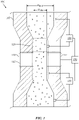
- FIG. 1 is a schematic view of at least a portion of apparatus comprising a multiphase flow meter (MPFM) 100 according to one or more aspects of the present disclosure.
- the MPFM 100 is operable to measure the flow rate of a multiphase fluid flowing in a conduit 110 of an installation at a well for producing hydrocarbons.
- Conduit 110 may be substantially vertical or substantially horizontal, or somewhere in between vertical and horizontal.
- the multiphase fluid comprises a liquid phase and a gas phase, wherein the liquid phase comprises one or more liquid hydrocarbons and perhaps water, whereas the gas phase comprises one or more gaseous hydrocarbons and perhaps steam.
- the GVF of the fluid flowing in the conduit 110 may vary from 0% (pure liquid) to 100% (pure gas).
- the flow regime within the conduit 110 may be characterized as bubble flow, slug flow, or wet gas flow, such as an annular-mist wet gas flow.
- Other flow regimes, such as plug and churn flows, are also within the scope of the present disclosure.
- Bubble flow may have a GVF of less than about 20%, with gas bubble sizes less than about 10% of the minimum diameter D MIN of the conduit 110, and perhaps a flow velocity sufficient to enable substantial mixing.
- Slug flow may comprise a succession of gas pockets and liquid plugs, both individually occupying a substantial portion of the diameter of the conduit 110 and perhaps having individual lengths up to a few meters.
- Wet gas flow may have a GVF of at least about 85%, and the flow velocity of the gas phase may be sufficiently high that the fluid substantially lacks liquid plugs.
- the minimum diameter D MIN may be the diameter of a Venturi portion 120 of the conduit 110, whereas a remaining portion of the conduit 110 may represent a maximum diameter D MAX .
- the minimum diameter D MIN may be less than the maximum diameter D MAX by an amount ranging between about 40% and about 80%. Although the minimum diameter D MIN may vary within the scope of the present disclosure, examples include about 29 mm and about 52 mm, among others.
- the MPFM 100 comprises one or more pressure sensors 130 operable to detect the pressure differential ⁇ p of the fluid traversing the transition between the minimum and maximum diameters D MIN and D MAX on the upstream and/or downstream side of the Venturi portion 120.
- the MPFM 100 also comprises a gas hold-up (GHU) sensor 140 comprising a nuclear emission source 142 and a corresponding detector 144 on opposing sides of the venturi 120.
- GHU is the fraction of gas present in a cross-section or interval of a conduit, such as the conduit 110.
- the GHU sensor 140 may be operable to emit and detect corresponding counts of gamma, X-ray, and/or other nuclear energy types, perhaps at different energy levels, whether serially or substantially simultaneously.
- the counts detected by the detector 144 may be utilized to determine GHU and/or other parameters of the multiphase fluid flow, whether by known or future-developed data processing techniques.
- An electronic device 150 is in electronic communication with the one or more pressure sensors 130 and the GHU sensor 140.
- the MPFM 100 may comprise the electronic device 150, or may instead comprise means for electronically communicating with the electronic device 150.
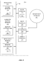
- FIG. 2 is a block diagram of an electronic device 200, at least a portion of which may form the electronic device 150 shown in FIG. 1 .
- the example electronic device 200 may execute transitory and/or non-transitory machine-readable instructions to implement one or more aspects of the methods and/or processes described herein, and/or to implement one or more aspects of the example flow regime recognition and/or flow model transition described herein.
- the electronic device 200 may be or comprise, for example, one or more processors, controllers, special-purpose computing devices, servers, personal computers, personal digital assistant (PDA) devices, smartphones, internet appliances, and/or other type(s) of electronic device(s).
- PDA personal digital assistant
- the electronic device 200 comprises a processor 212 such as, for example, a general-purpose programmable processor.
- the processor 212 may comprise a local memory 214, and may execute coded instructions 232 present in the local memory 214 and/or in another memory device.
- the processor 212 may execute, among other things, machine-readable instructions to implement the methods and/or processes described herein.
- the processor 212 may be, comprise, or be implemented by various types of processing units, such as one or more INTEL microprocessors, one or more microcontrollers from the ARM and/or PICO families of microcontrollers, one or more embedded soft/hard processors in one or more FPGAs, among other examples within the scope of the present disclosure.
- the processor 212 may be in communication with a main memory including a volatile (e.g., random-access) memory 218 and a non-volatile (e.g., read-only) memory 220 via a bus 210.
- the volatile memory 218 may be, comprise, or be implemented by static random-access memory (SRAM), synchronous dynamic random-access memory (SDRAM), dynamic random-access memory (DRAM), RAMBUS dynamic random-access memory (RDRAM), thyristor random-access memory (T-RAM), zero-capacitor random-access memory (Z-RAM), twin transistor random-access memory (TTRAM), and/or other types of random-access memory device.
- SRAM static random-access memory
- SDRAM synchronous dynamic random-access memory
- DRAM dynamic random-access memory
- RDRAM RAMBUS dynamic random-access memory
- T-RAM thyristor random-access memory
- Z-RAM zero-capacitor random-access memory
- TTRAM twin transistor random-access memory
- the non-volatile memory 1120 may be, comprise, or be implemented by flash memory, mask read-only memory, programmable read-only memory (PROM), erasable programmable read-only memory (EPROM), electrically erasable programmable read-only memory (EEPROM), non-volatile random-access memory (NVRAM), and/or other types of memory device.
- One or more memory controllers 216 may control access to the volatile memory 218, and one or more memory controllers 222 may control access to the non-volatile memory 220.
- the electronic device 200 may also comprise an interface circuit 224.
- the interface circuit 224 may be, comprise, or be implemented by various types of interface standards, such as Ethernet, universal serial bus (USB), and/or third generation input/output (3GIO), among others.
- One or more input devices 226 may be connected to the interface circuit 224.
- the input device(s) 226 may permit a user to enter data and/or commands into the processor 212.
- the input device(s) may be, comprise, or be implemented by, for example, a keyboard, a mouse, a touchscreen, a track-pad, a trackball, an isopoint, a voice recognition system, a motion sensor, and/or a scanner, among others.
- Motion sensors, radio frequency (RF) transmitters, receivers, and/or transceivers, transformers, wireless network devices, cellular network devices, and/or other cordless input devices may also be utilized.
- RF radio frequency
- One or more output devices 228 may also be connected to the interface circuit 224.
- the output devices 228 may be, comprise, or be implemented by, for example, display devices, printers, and/or speakers, among others.
- Example display devices may include a segment display, a cathode ray tube (CRT) display, a liquid crystal display (LCD), a plasma display, an organic light-emitting diode (OLED) display, and a three-dimensional (3D) display, among others.
- the interface circuit 224 may also comprise a graphics driver card.
- the interface circuit 224 may also comprise a modem, a network interface card, and/or another communication device, such as to facilitate the exchange of data with external computers and/or electronic devices via a network, including via Ethernet, DSL (digital subscriber line), POTS (plain old telephone service), cable, cellular telephone, satellite, Bluetooth, WiFi (IEEE 802.11), WiMax (Worldwide Interoperability for Microwave Access), UWB (ultra-wideband), and others.
- DSL digital subscriber line
- POTS plain old telephone service
- cable cable
- cellular telephone satellite
- Bluetooth Bluetooth
- WiFi IEEE 802.11
- WiMax Worldwide Interoperability for Microwave Access
- UWB ultra-wideband
- the electronic device 200 may also comprise one or more mass storage devices 230 operable to store machine-readable instructions and data.
- mass storage devices 230 include disk drives, hard disk drives, compact disk (CD) drives, digital versatile disk (DVD) drives, flash memory, and memory cards, among others.
- the coded instructions 232 may be stored in the local memory 214, the volatile memory 218, the non-volatile memory 220, the mass storage device 230, and/or on a removable storage medium 234, such as may be or comprise a CD or DVD.
- one or more aspects of the methods and or apparatus described herein may be embedded in other structures, such as an ASIC (application-specific integrated circuit) and/or other application-specific processors.
- ASIC application-specific integrated circuit
- FIG. 3 is a schematic view of a wellsite representing an example environment in which the MPFM 100 may be utilized according to one or more aspects of the present disclosure.
- the wellsite includes surface equipment 310 above a hydrocarbon geological formation 315 into which a wellbore 320 extends, and is in a production phase after drilling, completion, and perforating operations have been completed.
- the wellbore 320 may comprise one or more horizontal or deviated portions 325 extending from an initial, substantially vertical portion, and may be cased, partially cased, or uncased.
- a cased portion of the wellbore 320 may comprise an annulus 330 and a casing 335.
- the annulus 330 may be at least partially filled with cement or gravel pack, for example.
- Production zones 340 and 345 may comprise perforations and downhole production equipment 350, such as packers, tubing, and valves, among other examples.
- a multiphase fluid 355 may flow out of the production zones 340 and 345, through the downhole production equipment 350, and out of the wellbore 320 via a wellhead 360.
- the wellhead 360 is in fluid communication with production equipment 365 by one or more flowlines 370.
- the production equipment 365 may comprise a combination of one or more burners, heat exchangers, heaters, pressure reducers, pumps, separators, tanks, treaters, and/or other components, interconnected by various piping, tubing, and/or other conduits.
- One or more instances of the MPFM 100 described above may be installed in various locations at surface and downhole.
- an MPFM 100 may be in fluid communication with one of the flowlines 370, or with the downhole production equipment 350 of one or more of the production zones 340 and 345.
- the MPFM 100 at surface may be in electrical communication with various surface electronic apparatus 375, such as may comprise control and data acquisition equipment.
- One or more components of the surface electronic apparatus 375 may be embodied in, or otherwise substantially similar to, the electronic device 150 shown in FIG. 1 and/or one or more components of the electronic device 200 shown in FIG. 2 .
- the multiphase fluid 355 is directed to the conduit 110 of the MPFM 100.
- One or more of the electronic device 150, other components of the MPFM 100, one or more components of the electronic device 200, one or more components of the surface electronic apparatus 375, and/or other equipment components are independently and/or cooperatively operable to determine the overall GHU of the multiphase fluid in the conduit 110.
- One or more of the Electronic Instruments may also comprise a flow model, having one or more variables and/or parameters that may be adjusted and/or adapted depending on the detected flow regime, for determining volumetric flow rates of the constituent phases of different flow regimes, and may be independently and/or cooperatively operable to detect an actual flow regime of the multiphase fluid flow within the conduit 110.
- one or more of the Electronic Instruments may also determine which of the different flow model variables and/or parameters should be adapted and/or adjusted based on the determined GHU and the determined flow regime.
- One or more of the Electronic Instruments may also be independently and/or cooperatively operable to switch between the different flow model variables and/or parameters to be adjusted and/or adapted, perhaps automatically and gradually, in response to a detected change in the detected GHU and/or the detected flow regime.
- Determination of the flow regime by one or more of the Electronic Instruments is based on the time series analysis of high-frequency nuclear count rates detected by the GHU sensor 140.
- Theoretical statistics of nuclear counts of several energies are readily available due to predictable Poisson noise. Accordingly, measured data and/or statistics thereof will follow theoretical data and/or statistics thereof if the multiphase fluid flow exhibits stationarity, but will deviate if the fluid flow exhibits substantial nonstationarity.
- Stationarity refers to when a process or a field of any variable A(x,t) is statistically stationary if all statistics are invariant under a shift in time.
- a stationary process has the property that the mean, variance, and auto-correlation structure do not change over time.
- Stationarity may be indicated, visually speaking, by a flat looking series without trend and constant variance and constant auto-correlation structure over time with no periodic fluctuations. That is, the unchanging properties in a fluid flow exhibiting stationarity are limited to statistics of parameters and not directly to parameters themselves.
- i and j are indexes for different energy levels at which nuclear energy is emitted by the nuclear source 142, whether substantially simultaneously or serially, and ⁇ is the standard deviation or a factor related thereto.
- sensor 140 may be a venturi DP sensor used instead of or in addition to the high frequency nuclear count rate sensor. Determination of the flow regime by one or more of the Electronic Instruments may then be based on data from a fast venturi DP sensor.
- the venturi DP sensor could also indicate mixture density (gas content) for a multiphase flow of largely constant long-time-averaged mass flow rate.
- a stationarity indicator may thus be that of the spectral radius, p, which is a norm of the matrix Q, which may be computed utilizing a sample of the nuclear count data collected over a predetermined time period at a predetermined frequency.
- the predetermined time period may be about 1 minute, or about 5 minutes, or perhaps range between about 1 minute and about 5 minutes
- the predetermined frequency may be about 45 Hz or about 50 Hz.
- other time periods and frequencies are also within the scope of the present disclosure.
- FIG. 4 An example of the resulting stationarity indicator p is depicted in FIG. 4 .
- a predetermined stationarity ⁇ B may be the upper limit of stationarity for the purposes of subsequent actions in the context of the present disclosure, while another predetermined stationarity ⁇ A may similarly be the lower limit of nonstationarity.
- a stationarity indicator p between ⁇ B and ⁇ A may indicate that the multiphase fluid flow is a mix of stationary and nonstationary flow.
- one or more aspects introduced herein in the context of determining the stationarity indicator p may be applicable or readily adaptable for use with other or additional norms and/or measures that may be utilized in the determination of the stationarity indicator ⁇ .
- FIG. 4 demonstrates that the stationarity indicator p may be utilized to discriminate stationary flow from nonstationary flow at the transition between moderate gas content (slug flow) and high gas content (wet gas flow). Although only bubble flow, slug flow, and wet gas flow are shown in FIG. 4 , the stationarity indicator p may also be utilized to discriminate between the other flow regimes such as those previously discussed.
- the stationarity indicator p determined as above, in conjunction with the gas content also determined utilizing the MPFM 100, may then be utilized to select which of the one or more flow model variables stored by one or more of the Electronic Instruments described above should be utilized to determine volumetric flow rates of the different phases of the fluid flow.
- a first variable may be utilized for flow regimes having a low to moderate GHU regardless of the determined stationarity indicator p.
- the first variable may also be utilized for flow regimes having a moderate to high GHU if the flow is substantially stationary ( i.e. , ⁇ ⁇ ⁇ B ) .
- a second variable may be utilized for flow regimes having a moderate to high GHU if the flow is substantially nonstationary ( i.e., ⁇ > ⁇ A ).
- both variables may be adjusted and/or adapted simultaneously at all times, although such simultaneous adaptation/adjustment may be limited to when the GHU is greater than a predetermined GHU threshold and the stationarity indicator falls between first and second predetermined stationarity indicator thresholds, which may coincide with the substantially stationary threshold ⁇ B and the substantially nonstationary threshold ⁇ A .
- the predetermined GHU threshold may be 0.5, although other values are also within the scope of the present disclosure.
- the substantially stationary threshold ⁇ B may be about 20 and the substantially nonstationary threshold ⁇ A may be about 400, although other values are also within the scope of the present disclosure.
- the specific values may depend on the specific formulation of Q i,j and ⁇ , and perhaps on the shape and size of the apparatus, among other aspects which may affect flow stationarity.
- the multiphase flow rate may be determined as an adaptation or adjustment (continuously or otherwise) of the one or more flow model variables.
- FIG. 5 is a flow-chart diagram of at least a portion of a method (700) according to one or more aspects of the present disclosure.
- the method (700) may be executed by one or more of the Electronic Instruments described above.
- One or more aspects of the method (700) may also be performed by additional components shown in FIGS. 1-3 . As such, the following description refers to FIGS. 1-3 and 5 , collectively.
- the GHU sensor 140 of the MPFM 100 shown in FIG. 1 may be operated to obtain (710) nuclear count data associated with multiphase fluid flowing through the conduit 110 of the MPFM 100. This data may then be utilized to determine (720) attenuation attributable to the multiphase fluid.
- a flow model variable may then be selected, perhaps from a plurality of different flow model variables, based on the determined gas content, the determined stationarity, and/or the determined flow regime, and the multiphase fluid flow may be modeled by adjusting and/or adapting the selected flow model variable.
- the GHU may be determined (730) based on the determined attenuation.
- the method (700) may comprise determining (740) whether the determined GHU is less than a predetermined GHU threshold (e.g., 0.5). If the determined GHU is determined (740) to be less than the predetermined GHU threshold, then the multiphase fluid flow in the conduit 110 of the MPFM 100 may be modeled (745) by adjusting a first variable, referred to in FIG. 5 as VARIABLE A.
- the method (700) may then be repeated by, for example, obtaining (710) additional nuclear count data utilizing the MPFM 100, determining (720) attenuation, determining GHU (730), etc.
- the stationarity indicator p may be determined (750) as described above. If the determined stationarity indicator p is determined (760) to be less than a first predetermined stationarity indicator threshold (such as the upper stationarity threshold ⁇ B ), then the multiphase fluid flow in the conduit 110 of the MPFM 100 may be modeled (745) by adjusting VARIABLE A.
- a first predetermined stationarity indicator threshold such as the upper stationarity threshold ⁇ B
- the multiphase fluid flow in the conduit 110 of the MPFM 100 may be modeled (775) by adjusting a second variable, referred to in FIG. 5 as VARIABLE B.
- VARIABLE A and VARIBLE B may be both adjusted and/or adapted (780) as described above, and the multiphase fluid flow in the conduit 110 of the MPFM 100 may be modeled (785) utilizing the adjustment of both VARIABLE A and VARIABLE B. The method (700) may then be repeated.
- One or more aspects of the present disclosure are described in the context of determining flow regime based on time series analysis of high-frequency nuclear count rates detected by a nuclear sensor. However, one or more of such aspects may be applicable or readily adaptable for use with other types of sensors, including sensors having an available value of noise, whether it is accurate and/or predictable or a poor estimation.
- the present disclosure introduces a method comprising: operating a sensor of a multiphase flow meter to determine a physical property attributable to multiphase fluid flow in a conduit of the multiphase flow meter; determining a stationarity of the multiphase fluid flow based on the determined physical property in actual conditions compared to expected noise of the sensor in stationary flow conditions; selecting a one or more variables from a plurality of flow model variables based on a gas content of the multiphase fluid flow and the determined stationarity; and modeling the multiphase fluid flow utilizing the selected variable to be adjusted.
- the sensor may comprise a nuclear sensor and the physical property may be attenuation.
- the method may further comprise determining the expected noise.
- the predetermined plurality of possible flow regimes may comprise: a bubble flow regime in which the multiphase fluid flow has a gas volume fraction (GVF) less than about 20% and bubble sizes less than about 10% of a diameter of the conduit; a slug flow regime in which the multiphase fluid flow comprises a succession of gas pockets and liquid plugs alternatingly occupying a substantial portion of the diameter of the conduit; and a wet gas flow regime in which the multiphase fluid flow has a GVF of at least about 85% and substantially lacks liquid plugs.
- VVF gas volume fraction
- the sensor may comprise a nuclear source operable to emit nuclear energy through the conduit to an opposing nuclear detector, and determining the physical property attributable to the multiphase fluid flow may utilize statistical data based on nuclear energy detected by the nuclear detector.
- the nuclear energy detected by the detector may comprise nuclear energy emitted from the nuclear source at each of a plurality of different energy levels.
- the method may further comprise: determining a gas hold-up (GHU) of the multiphase fluid flow; and determining the gas content of the multiphase fluid flow based on the determined GHU.
- Selecting the flow model variable from the plurality of flow model variables based on the determined gas content and the determined stationarity may comprise: selecting a first variable if the determined gas content is less than a predetermined GHU threshold; selecting the first variable if the determined gas content is greater than the predetermined GHU threshold and the determined stationarity indicator is less than a first predetermined stationarity indicator threshold; selecting a second variable if the determined gas content is greater than the predetermined GHU threshold and the determined stationarity indicator is greater than a second predetermined stationarity indicator threshold; and selecting a third variable and/or parameter if the determined gas content is greater than the predetermined GHU threshold and the determined stationarity indicator is between the first and second predetermined stationarity indicator threshold.
- the method may further comprise: determining that the multiphase fluid flow is substantially stationary if the determined stationarity indicator is below the first predetermined stationarity indicator threshold; determining that the multiphase fluid flow is substantially nonstationary if the determined stationarity indicator is above the second predetermined stationarity indicator; and determining that the multiphase fluid flow is in transition between substantially stationary and substantially nonstationary if the determined stationarity indicator is between the first and second predetermined stationarity indicator thresholds.
- the third variable and/or parameter may be a combined adjustment of the first and second variables.
- the combined adjustment of the first and second variables may be a combined adjustment of both variables that is proportional to differences between the determined stationarity indicator and the first and second predetermined stationarity indicator thresholds.
- the combination of the first and second adjusted variables may be based on a function of the determined stationarity indicator.
- the present disclosure also introduces an apparatus comprising: a multiphase flow meter comprising: a conduit containing a multiphase fluid flow; a nuclear source; and a nuclear detector operable to detect nuclear energy emitted by the nuclear source through the conduit and multiphase fluid flow; and an electronic instrument operable for: determining a flow regime and a gas content of the multiphase fluid flow based on nuclear energy detected by the detector compared to expected noise of the nuclear detector in stationary flow conditions; determining a stationarity of the multiphase fluid flow based on the determined flow regime; selecting a flow model variable from a plurality of variables based on the determined gas content and the determined stationarity; and modeling the multiphase fluid flow by adjusting the selected variable.
- the apparatus may further comprise tubing extending from a production zone of a wellbore penetrating a subterranean formation, wherein the tubing is in fluid communication with the conduit.
- the present disclosure also introduces a method comprising: determining which of a plurality of fluid flow model variables an electronic instrument is adjusting and/or adapting to determine flow rates of each phase constituent of multiphase fluid flow within a conduit of a flow meter; operating the flow meter to determine a flow regime and a gas content of the multiphase fluid flow within the conduit; determining an indicator of stationarity of the multiphase fluid flow based on the determined flow regime and the determined gas content; and changing which of the plurality of flow model variables the electronic instrument adjusts to determine flow rates of each phase constituent of the multiphase fluid flow based on the determined gas content and the determined stationarity indicator.
- Changing which of the plurality of variables the electronic instrument adjusts may comprise changing from a first variable to a second variable.
- Changing which of the plurality of variables the electronic instrument adjusts may comprise changing from a first flow model variable to a combined adjustment of the first variable and a second variable.
Landscapes
- Physics & Mathematics (AREA)
- Life Sciences & Earth Sciences (AREA)
- Fluid Mechanics (AREA)
- Mining & Mineral Resources (AREA)
- Engineering & Computer Science (AREA)
- Geology (AREA)
- General Physics & Mathematics (AREA)
- General Life Sciences & Earth Sciences (AREA)
- Geophysics (AREA)
- Environmental & Geological Engineering (AREA)
- Geochemistry & Mineralogy (AREA)
- High Energy & Nuclear Physics (AREA)
- Electromagnetism (AREA)
- Measuring Volume Flow (AREA)
Claims (15)
- Procédé, comprenant :l'utilisation d'un capteur (140) d'un débitmètre multiphase (100) pour déterminer une propriété physique attribuable à un écoulement de fluide multiphase dans un conduit (110) du débitmètre multiphase (100) ;la détermination d'une stationnarité de l'écoulement de fluide multiphase sur la base de la propriété physique déterminée dans des conditions réelles par comparaison au rapport au bruit attendu du capteur dans des conditions d'écoulement stationnaires, dans lequel un processus ou un champ de n'importe quelle variable est dit être statistiquement stationnaire si toutes les statistiques sont invariantes sous un décalage dans le temps ;la sélection d'une variable parmi une pluralité de variables sur la base d'une teneur en gaz de l'écoulement de fluide multiphase et de la stationnarité déterminée ; et la modélisation de l'écoulement de fluide multiphase en ajustant la variable sélectionnée.
- Procédé selon la revendication 1, comprenant en outre la détermination d'un régime d'écoulement de l'écoulement de fluide multiphase sur la base de la teneur en gaz et de la stationnarité déterminée.
- Procédé selon la revendication 2, dans lequel la détermination du régime d'écoulement comprend la sélection du régime d'écoulement à partir d'une pluralité prédéfinie de régimes d'écoulement possibles.
- Procédé selon la revendication 3, dans lequel la pluralité prédéfinie de régimes d'écoulement possibles comprend :un régime d'écoulement à bulles dans lequel l'écoulement de fluide multiphase présente une fraction volumique de gaz (GVF) inférieure à environ 20 % et des tailles de bulles inférieures à environ 10 % d'un diamètre du conduit (110) ;un régime d'écoulement à bouchons dans lequel l'écoulement de fluide multiphase comprend une succession de poches de gaz et de bouchons de liquide occupant alternativement une partie importante du diamètre du conduit (110) ; etun régime de flux gazeux humide dans lequel l'écoulement de fluide multiphase présente un GVF d'au moins environ 85 % et est pratiquement dépourvu de bouchons liquides.
- Procédé selon la revendication 1, dans lequel le capteur (140) comprend une source nucléaire utilisable pour émettre de l'énergie nucléaire à travers le conduit (110) vers un détecteur nucléaire opposé et dans lequel la détermination de la propriété physique attribuable à l'écoulement de fluide multiphase utilise des données statistiques basées sur l'énergie nucléaire détectée par le détecteur nucléaire.
- Procédé selon la revendication 1, comprenant en outre :la détermination d'une rétention de gaz (GHU) de l'écoulement de fluide multiphase ; etla détermination de la teneur en gaz de l'écoulement de fluide multiphase sur la base du GHU déterminé.
- Procédé selon la revendication 6, dans lequel la sélection de la variable parmi la pluralité de variables sur la base de la teneur en gaz déterminée et de la stationnarité déterminée comprend au moins un parmi les éléments suivants :la sélection d'une première variable si la teneur en gaz déterminée est inférieure à un seuil de GHU prédéfini ;la sélection de la première variable destinée à un ajustement si la teneur en gaz déterminée est supérieure au seuil prédéfini de GHU et si un indicateur de stationnarité déterminé est inférieur à un premier seuil prédéfini d'indicateur de stationnarité ;la sélection d'une deuxième variable destinée à ajustement si la teneur en gaz déterminée est supérieure au seuil prédéfini de GHU et si l'indicateur de stationnarité déterminé est supérieur à un second seuil prédéfini d'indicateur de stationnarité ; etla sélection d'une troisième variable destinée à ajustement si la teneur en gaz déterminée est supérieure au seuil prédéfini de GHU et si l'indicateur de stationnarité déterminé se situe entre le premier et le second seuil prédéfini de l'indicateur de stationnarité.
- Procédé selon la revendication 7, comprenant en outre au moins une parmi :la détermination que l'écoulement de fluide multiphase est pratiquement stationnaire si l'indicateur de stationnarité déterminé est sous le premier seuil d'indicateur de stationnarité prédéfini ;la détermination que l'écoulement de fluide multiphase est pratiquement non-stationnaire si l'indicateur de stationnarité déterminé est au-dessus du second indicateur de stationnarité prédéfini ; etla détermination que l'écoulement de fluide multiphase est en transition entre un état pratiquement stationnaire et un état pratiquement non stationnaire si l'indicateur de stationnarité déterminé se situe entre les premier et second seuils d'indicateur de stationnarité prédéfinis.
- Procédé selon la revendication 7, dans lequel la troisième variable est une combinaison de l'ajustement des première et deuxième variables.
- Procédé selon la revendication 9, dans lequel la combinaison de l'ajustement des première et seconde variables est une combinaison proportionnelle aux différences entre l'indicateur de stationnarité déterminé et les premier et second seuils d'indicateur de stationnarité prédéfinis.
- Procédé selon la revendication 9, dans lequel la combinaison de l'ajustement des première et deuxième variables est basée sur une fonction de l'indicateur de stationnarité déterminé.
- Procédé selon la revendication 2, dans lequel :la détermination de la stationnarité est effectuée en déterminant un indicateur de stationnarité de l'écoulement de fluide multiphase sur la base du régime d'écoulement et de la teneur en gaz déterminés ; etla sélection de la variable est effectuée par :la détermination de celle d'une pluralité de variables de modèle d'écoulement un instrument électronique ajuste pour déterminer les débits de chaque phase constitutive d'un écoulement de fluide multiphase à l'intérieur d'un conduit d'un débitmètre ; etle changement de celle de la pluralité de variables du modèle d'écoulement l'instrument électronique ajuste pour déterminer les débits de chaque phase constitutive de l'écoulement de fluide multiphase sur la base de la teneur en gaz déterminée et de l'indicateur de stationnarité déterminé.
- Procédé selon la revendication 12, dans lequel le changement de celle de la pluralité de variables du modèle d'écoulement que l'instrument électronique utilise comprend le changement d'une première variable à une seconde variable.
- Procédé selon la revendication 12, dans lequel le changement de celle de la pluralité de variables de modèle d'écoulement que l'instrument électronique ajuste comprend le changement d'une première variable de modèle d'écoulement à un ajustement combiné de la première variable de modèle d'écoulement et d'une seconde variable de modèle d'écoulement.
- Appareil comprenant :un débitmètre multiphase (100) comprenant :un conduit (110) contenant un écoulement de fluide multiphase ;une source nucléaire (142) ; etun détecteur nucléaire (144) utilisable pour détecter l'énergie nucléaire émise par la source nucléaire à travers le conduit (110) et l'écoulement de fluide multiphase ; etun instrument électronique (150) utilisable pour :la détermination d'une teneur en gaz de l'écoulement de fluide multiphase sur la base de l'énergie nucléaire détectée par le détecteur nucléaire (144) par comparaison au bruit attendu du détecteur nucléaire (144) dans des conditions d'écoulement stationnaires ;la détermination d'une stationnarité de l'écoulement de fluide multiphase sur la base du taux de comptage nucléaire, dans lequel un processus ou un champ de n'importe quelle variable est dit être statistiquement stationnaire si toutes les statistiques sont invariantes sous un décalage dans le temps ;la sélection d'une variable parmi une pluralité de variables sur la base de la teneur en gaz déterminée et de la stationnarité déterminée ; etla modélisation de l'écoulement de fluide multiphase en ajustant la variable sélectionnée.
Applications Claiming Priority (2)
| Application Number | Priority Date | Filing Date | Title |
|---|---|---|---|
| US201361902048P | 2013-11-08 | 2013-11-08 | |
| PCT/US2014/064514 WO2015069995A1 (fr) | 2013-11-08 | 2014-11-07 | Reconnaissance de régime d'écoulement pour adaptation de modèle d'écoulement |
Publications (3)
| Publication Number | Publication Date |
|---|---|
| EP3066426A1 EP3066426A1 (fr) | 2016-09-14 |
| EP3066426A4 EP3066426A4 (fr) | 2017-06-14 |
| EP3066426B1 true EP3066426B1 (fr) | 2022-04-13 |
Family
ID=53042114
Family Applications (1)
| Application Number | Title | Priority Date | Filing Date |
|---|---|---|---|
| EP14861011.6A Active EP3066426B1 (fr) | 2013-11-08 | 2014-11-07 | Reconnaissance de régime d'écoulement pour adaptation de modèle d'écoulement |
Country Status (4)
| Country | Link |
|---|---|
| US (1) | US11226218B2 (fr) |
| EP (1) | EP3066426B1 (fr) |
| RU (1) | RU2632249C1 (fr) |
| WO (1) | WO2015069995A1 (fr) |
Families Citing this family (9)
| Publication number | Priority date | Publication date | Assignee | Title |
|---|---|---|---|---|
| CN105849536B (zh) | 2013-11-08 | 2021-07-30 | 普拉德研究及开发股份有限公司 | 利用谱去卷积进行谱分析 |
| US10533395B2 (en) * | 2016-01-26 | 2020-01-14 | Onesubsea Ip Uk Limited | Production assembly with integrated flow meter |
| WO2019015749A1 (fr) * | 2017-07-19 | 2019-01-24 | Schlumberger Technology Corporation | Amorçage d'écoulement par bouchons dans des modèles d'écoulement de fluide |
| US20200174149A1 (en) * | 2018-11-29 | 2020-06-04 | Bp Exploration Operating Company Limited | Event Detection Using DAS Features with Machine Learning |
| US11162348B2 (en) | 2019-10-17 | 2021-11-02 | Halliburton Energy Services, Inc. | Methods to improve fluid flow of a multi-phase mixture, methods to separate fluids of a multi-phase mixture, and multi-phase fluid mixture systems |
| EP4115153B1 (fr) * | 2020-03-05 | 2025-04-23 | Micro Motion, Inc. | Sélection d'un procédé de correction de mesure |
| US20220090947A1 (en) * | 2020-09-23 | 2022-03-24 | Saudi Arabian Oil Company | Wide range multi-phase flow meter |
| US12254252B2 (en) | 2021-06-30 | 2025-03-18 | Saudi Arabian Oil Company | Method and system for multiphase flow meter using updated flow model based on simulated data |
| CN115406575B (zh) * | 2022-08-31 | 2024-10-01 | 中国石油大学(北京) | 旋流气液分离器入口流型识别方法、装置及处理器 |
Citations (1)
| Publication number | Priority date | Publication date | Assignee | Title |
|---|---|---|---|---|
| WO2007089412A2 (fr) * | 2006-01-11 | 2007-08-09 | Cidra Corporation | Appareil et procédé de mesure d'un paramètre d'un écoulement polyphasique |
Family Cites Families (58)
| Publication number | Priority date | Publication date | Assignee | Title |
|---|---|---|---|---|
| US4688198A (en) | 1984-12-24 | 1987-08-18 | Schlumberger Technology Corporation | Entropy guided deconvolution of seismic signals |
| FR2616920B1 (fr) | 1987-06-19 | 1989-10-13 | Schlumberger Prospection | Inversion d'un profil sismique vertical en minimisant une fonction du type entropie |
| US4857729A (en) | 1988-04-22 | 1989-08-15 | Halliburton Logging Services, Inc. | Method of radioactive well logging |
| US5350925A (en) | 1988-12-08 | 1994-09-27 | Schlumberger Technology Corporation | Methods for determining values for earth formation properties |
| GB2237305B (en) | 1989-10-28 | 1993-03-31 | Schlumberger Prospection | Analysis of drilling solids samples |
| GB2237303A (en) | 1989-10-28 | 1991-05-01 | Services Tech Sedco Forex | Method of quantitative analysis of drilling fluid products |
| GB9014251D0 (en) * | 1990-06-27 | 1990-08-15 | British Petroleum Co Plc | Method for monitoring acoustic emissions |
| GB2259766B (en) | 1991-09-17 | 1995-08-23 | Schlumberger Services Petrol | A method to determine the phase composition of cement |
| GB2284887B (en) | 1993-12-17 | 1997-12-10 | Pumptech Nv | Method of analysing drilling fluids |
| US5550761A (en) * | 1994-02-08 | 1996-08-27 | Institut Francais Du Petrole | Method for modelling multiphase flows in pipelines |
| US5804820A (en) | 1994-09-16 | 1998-09-08 | Schlumberger Technology Corporation | Method for determining density of an earth formation |
| US5608215A (en) | 1994-09-16 | 1997-03-04 | Schlumberger Technology Corporation | Method and apparatus for determining density of earth formations |
| US5600073A (en) | 1994-11-02 | 1997-02-04 | Foster-Miller, Inc. | Method and system for analyzing a two phase flow |
| US8290721B2 (en) * | 1996-03-28 | 2012-10-16 | Rosemount Inc. | Flow measurement diagnostics |
| RU2184367C2 (ru) | 1996-05-02 | 2002-06-27 | Шелл Интернэшнл Рисерч Маатсхаппий Б.В. | Способ и измерительный прибор для определения состава многофазной жидкости |
| US5850623A (en) | 1997-03-14 | 1998-12-15 | Eastman Chemical Company | Method for standardizing raman spectrometers to obtain stable and transferable calibrations |
| FR2767919B1 (fr) | 1997-08-26 | 1999-10-29 | Schlumberger Services Petrol | Procede et dispositif de debitmetrie pour effluents petroliers |
| US6097786A (en) | 1998-05-18 | 2000-08-01 | Schlumberger Technology Corporation | Method and apparatus for measuring multiphase flows |
| EP1218728A1 (fr) | 1999-10-04 | 2002-07-03 | Daniel Industries, Inc., | Appareil et procede permettant de determiner les caracteristiques des effluents de puits de petrole dans des conditions d'ecoulement non homogenes |
| CN1325933C (zh) | 2000-08-21 | 2007-07-11 | V-目标技术有限公司 | 对坐标系统中放射性辐射源成像的系统 |
| US8565860B2 (en) | 2000-08-21 | 2013-10-22 | Biosensors International Group, Ltd. | Radioactive emission detector equipped with a position tracking system |
| GB2367613B (en) | 2000-10-05 | 2002-09-04 | Schlumberger Holdings | Fluid density monitor |
| FR2818379B1 (fr) | 2000-12-19 | 2003-03-14 | Schlumberger Services Petrol | Dispositif et procede pour la caracterisation d'effluents multiphasiques |
| US6820702B2 (en) * | 2002-08-27 | 2004-11-23 | Noble Drilling Services Inc. | Automated method and system for recognizing well control events |
| GB2401766B (en) | 2003-03-11 | 2006-03-15 | Symetrica Ltd | Improved gamma-ray camera system |
| US6958604B2 (en) | 2003-06-23 | 2005-10-25 | Schlumberger Technology Corporation | Apparatus and methods for J-edit nuclear magnetic resonance measurement |
| GB2408101B (en) | 2003-11-14 | 2007-04-04 | Schlumberger Holdings | High-frequency processing of seismic vibrator data |
| US7082368B2 (en) | 2004-06-04 | 2006-07-25 | Schlumberger Technology Corporation | Seismic event correlation and Vp-Vs estimation |
| AR048373A1 (es) * | 2004-07-08 | 2006-04-26 | Spinlock Srl | Un dispositivo y un metodo para medir en forma directa y en tiempo real, la proporcion y el caudal de los distintos componentes que conforman un fluido complejo multicomponente , una disposicion de linea de produccion para un fluido complejo multicomponente que utiliza dicho dispositivo y un metodo |
| KR20070062975A (ko) | 2004-08-26 | 2007-06-18 | 캔버라 인더스트리스, 인코포레이티드 | 핵종 식별 시스템 |
| US7202456B2 (en) | 2004-09-29 | 2007-04-10 | Precision Energy Services, Inc. | Gain stabilization apparatus and methods for spectral gamma ray measurement systems |
| EP1828977B1 (fr) | 2004-11-17 | 2013-09-11 | Koninklijke Philips Electronics N.V. | Restauration d'une image planaire 2d de medecine nucleaire par une deconvolution iterative contrainte |
| GB2425838B (en) | 2005-05-03 | 2007-06-27 | Westerngeco Seismic Holdings | Source signature deconvolution method |
| BRPI0612768A2 (pt) | 2005-07-07 | 2010-11-30 | Cidra Corp | sistema de medição de fluxo multifásico que tem um separador de fluìdo |
| US7512034B2 (en) | 2005-09-15 | 2009-03-31 | Schlumberger Technology Corporation | Drill noise seismic data acquisition and processing methods |
| GB2430493B (en) | 2005-09-23 | 2008-04-23 | Schlumberger Holdings | Systems and methods for measuring multiphase flow in a hydrocarbon transporting pipeline |
| US7482578B2 (en) | 2006-06-12 | 2009-01-27 | Lonkar Services, Ltd. | Gamma radiation spectral logging system and method for processing gamma radiation spectra |
| US7684540B2 (en) | 2006-06-20 | 2010-03-23 | Schlumberger Technology Corporation | Apparatus and method for fluid phase fraction determination using x-rays |
| US7617055B2 (en) | 2006-08-28 | 2009-11-10 | Invensys Systems, Inc. | Wet gas measurement |
| EP1970702A1 (fr) | 2007-03-05 | 2008-09-17 | Services Pétroliers Schlumberger | Détection d'un élément d'un flux |
| US8259299B2 (en) | 2007-06-21 | 2012-09-04 | Rf Science & Technology Inc. | Gas scanning and analysis |
| WO2009036337A2 (fr) | 2007-09-12 | 2009-03-19 | University Of Florida Research Foundation, Inc. | Procédé et appareil pour la déconvolution spectrale de spectres de détecteur |
| US8472582B2 (en) | 2007-10-30 | 2013-06-25 | Schlumberger Technology Corporation | Method and apparatus for determining volume fractions in a multiphase flow |
| US7903782B2 (en) | 2007-12-19 | 2011-03-08 | Schlumberger Technology Corporation | Apparatus and method for fluid phase fraction determination using x-rays optimized for wet gas |
| US8061186B2 (en) * | 2008-03-26 | 2011-11-22 | Expro Meters, Inc. | System and method for providing a compositional measurement of a mixture having entrained gas |
| CN101261235B (zh) | 2008-05-06 | 2010-12-08 | 罗平安 | 原油中含气率和含水率的双能χ射线测量方法 |
| DE102008059920B4 (de) | 2008-12-02 | 2016-07-14 | Krohne Meßtechnik GmbH & Co KG | Verfahren zum Betreiben eines Resonanzmeßsystems und diesbezügliches Resonanzmeßsystem |
| FR2939896B1 (fr) | 2008-12-12 | 2011-05-06 | Geoservices Equipements | Dispositif d'emission d'un premier faisceau de photons gamma de haute energie et d'un deuxieme faisceau de photons gamma de plus basse energie, ensemble de mesure et procede associe |
| GB2482271B (en) * | 2009-05-20 | 2016-07-13 | Schlumberger Holdings | System, method and apparatus for measuring multiphase flow |
| EP2431716A1 (fr) * | 2010-06-30 | 2012-03-21 | Services Petroliers Schlumberger | Débitmètre multi-phase et son procédé de correction |
| US9217802B2 (en) | 2011-04-05 | 2015-12-22 | Schlumberger Technology Corporation | Seismic image enhancement |
| EP2710413B1 (fr) | 2011-05-17 | 2016-12-14 | Services Pétroliers Schlumberger | Analyseur d'amplitude d'impulsions à haut débit |
| US9720124B2 (en) | 2011-08-10 | 2017-08-01 | Schlumberger Technology Corporation | Logging in gas shale and other unconventional reservoirs |
| US9528874B2 (en) | 2011-08-16 | 2016-12-27 | Gushor, Inc. | Reservoir sampling tools and methods |
| EP2574919B1 (fr) | 2011-09-29 | 2014-05-07 | Service Pétroliers Schlumberger | Appareil et procédé pour la détermination de la fraction de la phase liquide au moyen de rayons X |
| US20140110105A1 (en) * | 2012-10-23 | 2014-04-24 | Halliburton Energy Services, Inc. | Systems and Methods of Monitoring a Multiphase Fluid |
| EP2871478B1 (fr) | 2013-11-08 | 2020-04-29 | Services Petroliers Schlumberger SA | Méthode d'analyse de fluide et débitmètre multiphase |
| CN105849536B (zh) | 2013-11-08 | 2021-07-30 | 普拉德研究及开发股份有限公司 | 利用谱去卷积进行谱分析 |
-
2014
- 2014-11-07 EP EP14861011.6A patent/EP3066426B1/fr active Active
- 2014-11-07 US US15/034,759 patent/US11226218B2/en not_active Expired - Fee Related
- 2014-11-07 WO PCT/US2014/064514 patent/WO2015069995A1/fr not_active Ceased
- 2014-11-07 RU RU2016120730A patent/RU2632249C1/ru active
Patent Citations (1)
| Publication number | Priority date | Publication date | Assignee | Title |
|---|---|---|---|---|
| WO2007089412A2 (fr) * | 2006-01-11 | 2007-08-09 | Cidra Corporation | Appareil et procédé de mesure d'un paramètre d'un écoulement polyphasique |
Non-Patent Citations (3)
| Title |
|---|
| CHUL HWA SONG ET AL: "Investigation of bubble flow developments and its transition based on the instability of void fraction waves", INTERNATIONAL JOURNAL OF MULTIPHASE FLOW., vol. 21, no. 3, 1 June 1995 (1995-06-01), NL, pages 381 - 404, XP055713372, ISSN: 0301-9322, DOI: 10.1016/0301-9322(94)00079-Y * |
| KLEIN, F.L.;SELEGHIM JUNIOR, P. AND HERVIEU, E.: "Time-frequency analysis of intermittent two-phase flows in horizontal piping", JOURNAL OF THE BRAZILIAN SOCIETY OF MECHANICAL SCIENCES AND ENGINEERING, vol. 26, no. 2, 2004, pages 174 - 179, Retrieved from the Internet <URL:http://dx.doi.org/10.1590/S1678-58782004000200009> [retrieved on 20181022] * |
| SOLDATI, A.; PAGLIANTI, A.; GIONA, M.: "Identification of two phase flow regimes via diffusional analysis of experimental time series", EXPERIMENTS IN FLUIDS, vol. 21, no. 3, July 1996 (1996-07-01), pages 151 - 160 * |
Also Published As
| Publication number | Publication date |
|---|---|
| RU2632249C1 (ru) | 2017-10-03 |
| US20160290841A1 (en) | 2016-10-06 |
| US11226218B2 (en) | 2022-01-18 |
| WO2015069995A1 (fr) | 2015-05-14 |
| EP3066426A1 (fr) | 2016-09-14 |
| EP3066426A4 (fr) | 2017-06-14 |
Similar Documents
| Publication | Publication Date | Title |
|---|---|---|
| EP3066426B1 (fr) | Reconnaissance de régime d'écoulement pour adaptation de modèle d'écoulement | |
| US20230408313A1 (en) | Conductivity probe fluid property measurement systems and related methods | |
| EP3289319B1 (fr) | Débitmètres à phases multiples et procédés associés | |
| CN104141490B (zh) | 有水气藏单井水侵情况判断及气井产量控制方法和装置 | |
| US20210340869A1 (en) | Method and system for determining the flow rates of multiphase and/or multi-component fluid produced from an oil and gas well | |
| CN111878073B (zh) | 一种致密储层压裂效果评价方法及装置 | |
| CN107045671A (zh) | 产水气井积液风险预测方法 | |
| US20120303281A1 (en) | Enhanced dynamic well model for reservoir pressure determination | |
| WO2014074474A2 (fr) | Prévision de la performance de réservoirs de condensat de gaz | |
| NO342311B1 (no) | System, fremgangsmåte og apparat for å måle flerfasestrømning | |
| US10908007B1 (en) | Multiphase flow metering system for horizontal well compartments | |
| US20190316942A1 (en) | Methodologies and apparatus for the recognition of production tests stability | |
| Warren et al. | An evaluation of the significance of permeability measurements | |
| Taghavi et al. | The impact of autonomous inflow control valve on improved oil recovery in a thin-oil-rim reservoir | |
| EP2708858A1 (fr) | Procédé et appareil pour déterminer les paramètres d'un fluide | |
| CN107725035B (zh) | 一种用于非均匀产液水平井判别来水方向的压力监测方法 | |
| CN104265259A (zh) | 产能跟踪与评价方法 | |
| US20230194320A1 (en) | Virtual flow rate test | |
| CN103375161B (zh) | 监测孔隙型地层压力梯度的方法 | |
| Bhargava et al. | A case study-determination of accurate liquid level and its applications in CBM wells | |
| CN112443317A (zh) | 一种模拟化学驱注入井井口压力确定方法及系统 | |
| RU2768341C1 (ru) | Способ прогнозирования дебита скважин с учетом анизотропии проницаемости карбонатных горных пород | |
| Theuveny et al. | The Identification of Condensate Banking With Multiphase Flowmeters–A Case Study | |
| CN119491686B (zh) | 一种致密砂岩气藏可动水饱和度评价方法及系统 | |
| CN114607335B (zh) | 确定体积压裂对应的压裂液流量方法 |
Legal Events
| Date | Code | Title | Description |
|---|---|---|---|
| PUAI | Public reference made under article 153(3) epc to a published international application that has entered the european phase |
Free format text: ORIGINAL CODE: 0009012 |
|
| 17P | Request for examination filed |
Effective date: 20160503 |
|
| AK | Designated contracting states |
Kind code of ref document: A1 Designated state(s): AL AT BE BG CH CY CZ DE DK EE ES FI FR GB GR HR HU IE IS IT LI LT LU LV MC MK MT NL NO PL PT RO RS SE SI SK SM TR |
|
| AX | Request for extension of the european patent |
Extension state: BA ME |
|
| DAX | Request for extension of the european patent (deleted) | ||
| STAA | Information on the status of an ep patent application or granted ep patent |
Free format text: STATUS: EXAMINATION IS IN PROGRESS |
|
| A4 | Supplementary search report drawn up and despatched |
Effective date: 20170517 |
|
| RIC1 | Information provided on ipc code assigned before grant |
Ipc: G01F 1/58 20060101AFI20170511BHEP |
|
| 17Q | First examination report despatched |
Effective date: 20170601 |
|
| REG | Reference to a national code |
Ref country code: DE Ref legal event code: R079 Ref document number: 602014083267 Country of ref document: DE Free format text: PREVIOUS MAIN CLASS: G01F0001580000 Ipc: G01F0001740000 |
|
| RIC1 | Information provided on ipc code assigned before grant |
Ipc: G01F 1/74 20060101AFI20200619BHEP |
|
| GRAP | Despatch of communication of intention to grant a patent |
Free format text: ORIGINAL CODE: EPIDOSNIGR1 |
|
| STAA | Information on the status of an ep patent application or granted ep patent |
Free format text: STATUS: GRANT OF PATENT IS INTENDED |
|
| INTG | Intention to grant announced |
Effective date: 20211027 |
|
| GRAJ | Information related to disapproval of communication of intention to grant by the applicant or resumption of examination proceedings by the epo deleted |
Free format text: ORIGINAL CODE: EPIDOSDIGR1 |
|
| GRAS | Grant fee paid |
Free format text: ORIGINAL CODE: EPIDOSNIGR3 |
|
| GRAA | (expected) grant |
Free format text: ORIGINAL CODE: 0009210 |
|
| STAA | Information on the status of an ep patent application or granted ep patent |
Free format text: STATUS: THE PATENT HAS BEEN GRANTED |
|
| INTG | Intention to grant announced |
Effective date: 20211027 |
|
| AK | Designated contracting states |
Kind code of ref document: B1 Designated state(s): AL AT BE BG CH CY CZ DE DK EE ES FI FR GB GR HR HU IE IS IT LI LT LU LV MC MK MT NL NO PL PT RO RS SE SI SK SM TR |
|
| REG | Reference to a national code |
Ref country code: GB Ref legal event code: FG4D |
|
| REG | Reference to a national code |
Ref country code: CH Ref legal event code: EP |
|
| REG | Reference to a national code |
Ref country code: DE Ref legal event code: R096 Ref document number: 602014083267 Country of ref document: DE |
|
| REG | Reference to a national code |
Ref country code: IE Ref legal event code: FG4D |
|
| REG | Reference to a national code |
Ref country code: AT Ref legal event code: REF Ref document number: 1483741 Country of ref document: AT Kind code of ref document: T Effective date: 20220515 |
|
| REG | Reference to a national code |
Ref country code: LT Ref legal event code: MG9D |
|
| REG | Reference to a national code |
Ref country code: NL Ref legal event code: MP Effective date: 20220413 |
|
| REG | Reference to a national code |
Ref country code: NO Ref legal event code: T2 Effective date: 20220413 |
|
| REG | Reference to a national code |
Ref country code: AT Ref legal event code: MK05 Ref document number: 1483741 Country of ref document: AT Kind code of ref document: T Effective date: 20220413 |
|
| PG25 | Lapsed in a contracting state [announced via postgrant information from national office to epo] |
Ref country code: NL Free format text: LAPSE BECAUSE OF FAILURE TO SUBMIT A TRANSLATION OF THE DESCRIPTION OR TO PAY THE FEE WITHIN THE PRESCRIBED TIME-LIMIT Effective date: 20220413 |
|
| PG25 | Lapsed in a contracting state [announced via postgrant information from national office to epo] |
Ref country code: SE Free format text: LAPSE BECAUSE OF FAILURE TO SUBMIT A TRANSLATION OF THE DESCRIPTION OR TO PAY THE FEE WITHIN THE PRESCRIBED TIME-LIMIT Effective date: 20220413 Ref country code: PT Free format text: LAPSE BECAUSE OF FAILURE TO SUBMIT A TRANSLATION OF THE DESCRIPTION OR TO PAY THE FEE WITHIN THE PRESCRIBED TIME-LIMIT Effective date: 20220816 Ref country code: LT Free format text: LAPSE BECAUSE OF FAILURE TO SUBMIT A TRANSLATION OF THE DESCRIPTION OR TO PAY THE FEE WITHIN THE PRESCRIBED TIME-LIMIT Effective date: 20220413 Ref country code: HR Free format text: LAPSE BECAUSE OF FAILURE TO SUBMIT A TRANSLATION OF THE DESCRIPTION OR TO PAY THE FEE WITHIN THE PRESCRIBED TIME-LIMIT Effective date: 20220413 Ref country code: GR Free format text: LAPSE BECAUSE OF FAILURE TO SUBMIT A TRANSLATION OF THE DESCRIPTION OR TO PAY THE FEE WITHIN THE PRESCRIBED TIME-LIMIT Effective date: 20220714 Ref country code: FI Free format text: LAPSE BECAUSE OF FAILURE TO SUBMIT A TRANSLATION OF THE DESCRIPTION OR TO PAY THE FEE WITHIN THE PRESCRIBED TIME-LIMIT Effective date: 20220413 Ref country code: ES Free format text: LAPSE BECAUSE OF FAILURE TO SUBMIT A TRANSLATION OF THE DESCRIPTION OR TO PAY THE FEE WITHIN THE PRESCRIBED TIME-LIMIT Effective date: 20220413 Ref country code: BG Free format text: LAPSE BECAUSE OF FAILURE TO SUBMIT A TRANSLATION OF THE DESCRIPTION OR TO PAY THE FEE WITHIN THE PRESCRIBED TIME-LIMIT Effective date: 20220713 Ref country code: AT Free format text: LAPSE BECAUSE OF FAILURE TO SUBMIT A TRANSLATION OF THE DESCRIPTION OR TO PAY THE FEE WITHIN THE PRESCRIBED TIME-LIMIT Effective date: 20220413 |
|
| PG25 | Lapsed in a contracting state [announced via postgrant information from national office to epo] |
Ref country code: RS Free format text: LAPSE BECAUSE OF FAILURE TO SUBMIT A TRANSLATION OF THE DESCRIPTION OR TO PAY THE FEE WITHIN THE PRESCRIBED TIME-LIMIT Effective date: 20220413 Ref country code: PL Free format text: LAPSE BECAUSE OF FAILURE TO SUBMIT A TRANSLATION OF THE DESCRIPTION OR TO PAY THE FEE WITHIN THE PRESCRIBED TIME-LIMIT Effective date: 20220413 Ref country code: LV Free format text: LAPSE BECAUSE OF FAILURE TO SUBMIT A TRANSLATION OF THE DESCRIPTION OR TO PAY THE FEE WITHIN THE PRESCRIBED TIME-LIMIT Effective date: 20220413 Ref country code: IS Free format text: LAPSE BECAUSE OF FAILURE TO SUBMIT A TRANSLATION OF THE DESCRIPTION OR TO PAY THE FEE WITHIN THE PRESCRIBED TIME-LIMIT Effective date: 20220813 |
|
| REG | Reference to a national code |
Ref country code: DE Ref legal event code: R097 Ref document number: 602014083267 Country of ref document: DE |
|
| PG25 | Lapsed in a contracting state [announced via postgrant information from national office to epo] |
Ref country code: SM Free format text: LAPSE BECAUSE OF FAILURE TO SUBMIT A TRANSLATION OF THE DESCRIPTION OR TO PAY THE FEE WITHIN THE PRESCRIBED TIME-LIMIT Effective date: 20220413 Ref country code: SK Free format text: LAPSE BECAUSE OF FAILURE TO SUBMIT A TRANSLATION OF THE DESCRIPTION OR TO PAY THE FEE WITHIN THE PRESCRIBED TIME-LIMIT Effective date: 20220413 Ref country code: RO Free format text: LAPSE BECAUSE OF FAILURE TO SUBMIT A TRANSLATION OF THE DESCRIPTION OR TO PAY THE FEE WITHIN THE PRESCRIBED TIME-LIMIT Effective date: 20220413 Ref country code: EE Free format text: LAPSE BECAUSE OF FAILURE TO SUBMIT A TRANSLATION OF THE DESCRIPTION OR TO PAY THE FEE WITHIN THE PRESCRIBED TIME-LIMIT Effective date: 20220413 Ref country code: DK Free format text: LAPSE BECAUSE OF FAILURE TO SUBMIT A TRANSLATION OF THE DESCRIPTION OR TO PAY THE FEE WITHIN THE PRESCRIBED TIME-LIMIT Effective date: 20220413 Ref country code: CZ Free format text: LAPSE BECAUSE OF FAILURE TO SUBMIT A TRANSLATION OF THE DESCRIPTION OR TO PAY THE FEE WITHIN THE PRESCRIBED TIME-LIMIT Effective date: 20220413 |
|
| PLBE | No opposition filed within time limit |
Free format text: ORIGINAL CODE: 0009261 |
|
| STAA | Information on the status of an ep patent application or granted ep patent |
Free format text: STATUS: NO OPPOSITION FILED WITHIN TIME LIMIT |
|
| 26N | No opposition filed |
Effective date: 20230116 |
|
| PG25 | Lapsed in a contracting state [announced via postgrant information from national office to epo] |
Ref country code: AL Free format text: LAPSE BECAUSE OF FAILURE TO SUBMIT A TRANSLATION OF THE DESCRIPTION OR TO PAY THE FEE WITHIN THE PRESCRIBED TIME-LIMIT Effective date: 20220413 |
|
| PG25 | Lapsed in a contracting state [announced via postgrant information from national office to epo] |
Ref country code: SI Free format text: LAPSE BECAUSE OF FAILURE TO SUBMIT A TRANSLATION OF THE DESCRIPTION OR TO PAY THE FEE WITHIN THE PRESCRIBED TIME-LIMIT Effective date: 20220413 |
|
| REG | Reference to a national code |
Ref country code: DE Ref legal event code: R119 Ref document number: 602014083267 Country of ref document: DE |
|
| PG25 | Lapsed in a contracting state [announced via postgrant information from national office to epo] |
Ref country code: MC Free format text: LAPSE BECAUSE OF FAILURE TO SUBMIT A TRANSLATION OF THE DESCRIPTION OR TO PAY THE FEE WITHIN THE PRESCRIBED TIME-LIMIT Effective date: 20220413 |
|
| REG | Reference to a national code |
Ref country code: CH Ref legal event code: PL |
|
| REG | Reference to a national code |
Ref country code: BE Ref legal event code: MM Effective date: 20221130 |
|
| PG25 | Lapsed in a contracting state [announced via postgrant information from national office to epo] |
Ref country code: LI Free format text: LAPSE BECAUSE OF NON-PAYMENT OF DUE FEES Effective date: 20221130 Ref country code: CH Free format text: LAPSE BECAUSE OF NON-PAYMENT OF DUE FEES Effective date: 20221130 |
|
| PG25 | Lapsed in a contracting state [announced via postgrant information from national office to epo] |
Ref country code: LU Free format text: LAPSE BECAUSE OF NON-PAYMENT OF DUE FEES Effective date: 20221107 |
|
| PG25 | Lapsed in a contracting state [announced via postgrant information from national office to epo] |
Ref country code: IE Free format text: LAPSE BECAUSE OF NON-PAYMENT OF DUE FEES Effective date: 20221107 Ref country code: DE Free format text: LAPSE BECAUSE OF NON-PAYMENT OF DUE FEES Effective date: 20230601 |
|
| PG25 | Lapsed in a contracting state [announced via postgrant information from national office to epo] |
Ref country code: FR Free format text: LAPSE BECAUSE OF NON-PAYMENT OF DUE FEES Effective date: 20221130 Ref country code: BE Free format text: LAPSE BECAUSE OF NON-PAYMENT OF DUE FEES Effective date: 20221130 |
|
| P01 | Opt-out of the competence of the unified patent court (upc) registered |
Effective date: 20231208 |
|
| PG25 | Lapsed in a contracting state [announced via postgrant information from national office to epo] |
Ref country code: IT Free format text: LAPSE BECAUSE OF FAILURE TO SUBMIT A TRANSLATION OF THE DESCRIPTION OR TO PAY THE FEE WITHIN THE PRESCRIBED TIME-LIMIT Effective date: 20220413 |
|
| PG25 | Lapsed in a contracting state [announced via postgrant information from national office to epo] |
Ref country code: HU Free format text: LAPSE BECAUSE OF FAILURE TO SUBMIT A TRANSLATION OF THE DESCRIPTION OR TO PAY THE FEE WITHIN THE PRESCRIBED TIME-LIMIT; INVALID AB INITIO Effective date: 20141107 |
|
| PG25 | Lapsed in a contracting state [announced via postgrant information from national office to epo] |
Ref country code: CY Free format text: LAPSE BECAUSE OF FAILURE TO SUBMIT A TRANSLATION OF THE DESCRIPTION OR TO PAY THE FEE WITHIN THE PRESCRIBED TIME-LIMIT Effective date: 20220413 |
|
| PG25 | Lapsed in a contracting state [announced via postgrant information from national office to epo] |
Ref country code: MK Free format text: LAPSE BECAUSE OF FAILURE TO SUBMIT A TRANSLATION OF THE DESCRIPTION OR TO PAY THE FEE WITHIN THE PRESCRIBED TIME-LIMIT Effective date: 20220413 |
|
| PG25 | Lapsed in a contracting state [announced via postgrant information from national office to epo] |
Ref country code: TR Free format text: LAPSE BECAUSE OF FAILURE TO SUBMIT A TRANSLATION OF THE DESCRIPTION OR TO PAY THE FEE WITHIN THE PRESCRIBED TIME-LIMIT Effective date: 20220413 |
|
| PG25 | Lapsed in a contracting state [announced via postgrant information from national office to epo] |
Ref country code: MT Free format text: LAPSE BECAUSE OF FAILURE TO SUBMIT A TRANSLATION OF THE DESCRIPTION OR TO PAY THE FEE WITHIN THE PRESCRIBED TIME-LIMIT Effective date: 20220413 |
|
| PGFP | Annual fee paid to national office [announced via postgrant information from national office to epo] |
Ref country code: GB Payment date: 20240919 Year of fee payment: 11 |
|
| PG25 | Lapsed in a contracting state [announced via postgrant information from national office to epo] |
Ref country code: BG Free format text: LAPSE BECAUSE OF FAILURE TO SUBMIT A TRANSLATION OF THE DESCRIPTION OR TO PAY THE FEE WITHIN THE PRESCRIBED TIME-LIMIT Effective date: 20220413 |
|
| PG25 | Lapsed in a contracting state [announced via postgrant information from national office to epo] |
Ref country code: BG Free format text: LAPSE BECAUSE OF FAILURE TO SUBMIT A TRANSLATION OF THE DESCRIPTION OR TO PAY THE FEE WITHIN THE PRESCRIBED TIME-LIMIT Effective date: 20220413 |
|
| PGFP | Annual fee paid to national office [announced via postgrant information from national office to epo] |
Ref country code: NO Payment date: 20241111 Year of fee payment: 11 |