EP3066496B1 - Vorrichtung und verfahren zur detektion von neutronen und gamma-strahlung - Google Patents
Vorrichtung und verfahren zur detektion von neutronen und gamma-strahlung Download PDFInfo
- Publication number
- EP3066496B1 EP3066496B1 EP14828278.3A EP14828278A EP3066496B1 EP 3066496 B1 EP3066496 B1 EP 3066496B1 EP 14828278 A EP14828278 A EP 14828278A EP 3066496 B1 EP3066496 B1 EP 3066496B1
- Authority
- EP
- European Patent Office
- Prior art keywords
- layers
- scintillator
- gamma rays
- event
- detector
- Prior art date
- Legal status (The legal status is an assumption and is not a legal conclusion. Google has not performed a legal analysis and makes no representation as to the accuracy of the status listed.)
- Active
Links
- 238000000034 method Methods 0.000 title claims description 23
- 239000006096 absorbing agent Substances 0.000 claims description 54
- 239000000463 material Substances 0.000 claims description 40
- 229910052688 Gadolinium Inorganic materials 0.000 claims description 17
- 230000005855 radiation Effects 0.000 claims description 17
- UIWYJDYFSGRHKR-UHFFFAOYSA-N gadolinium atom Chemical compound [Gd] UIWYJDYFSGRHKR-UHFFFAOYSA-N 0.000 claims description 16
- 238000007405 data analysis Methods 0.000 claims description 15
- 229920003023 plastic Polymers 0.000 claims description 14
- 230000003993 interaction Effects 0.000 claims description 11
- 229910052793 cadmium Inorganic materials 0.000 claims description 7
- 239000011358 absorbing material Substances 0.000 claims description 6
- BDOSMKKIYDKNTQ-UHFFFAOYSA-N cadmium atom Chemical compound [Cd] BDOSMKKIYDKNTQ-UHFFFAOYSA-N 0.000 claims description 6
- 239000011149 active material Substances 0.000 claims description 4
- 238000004458 analytical method Methods 0.000 claims description 4
- 229920002102 polyvinyl toluene Polymers 0.000 claims description 3
- 230000008878 coupling Effects 0.000 claims description 2
- 238000010168 coupling process Methods 0.000 claims description 2
- 238000005859 coupling reaction Methods 0.000 claims description 2
- 238000012544 monitoring process Methods 0.000 claims description 2
- 230000003287 optical effect Effects 0.000 claims description 2
- 238000001514 detection method Methods 0.000 description 16
- 238000001228 spectrum Methods 0.000 description 10
- 238000005259 measurement Methods 0.000 description 9
- 230000008569 process Effects 0.000 description 6
- 230000002285 radioactive effect Effects 0.000 description 6
- 230000006870 function Effects 0.000 description 5
- 229940075613 gadolinium oxide Drugs 0.000 description 5
- 229910001938 gadolinium oxide Inorganic materials 0.000 description 5
- CMIHHWBVHJVIGI-UHFFFAOYSA-N gadolinium(iii) oxide Chemical compound [O-2].[O-2].[O-2].[Gd+3].[Gd+3] CMIHHWBVHJVIGI-UHFFFAOYSA-N 0.000 description 5
- 230000000875 corresponding effect Effects 0.000 description 4
- 239000007787 solid Substances 0.000 description 4
- 238000010521 absorption reaction Methods 0.000 description 3
- 230000005251 gamma ray Effects 0.000 description 3
- 229910052751 metal Inorganic materials 0.000 description 3
- 239000002245 particle Substances 0.000 description 3
- 230000009467 reduction Effects 0.000 description 3
- 230000002269 spontaneous effect Effects 0.000 description 3
- 230000008901 benefit Effects 0.000 description 2
- WTEOIRVLGSZEPR-UHFFFAOYSA-N boron trifluoride Chemical compound FB(F)F WTEOIRVLGSZEPR-UHFFFAOYSA-N 0.000 description 2
- 239000002131 composite material Substances 0.000 description 2
- 238000010276 construction Methods 0.000 description 2
- 238000011161 development Methods 0.000 description 2
- 238000010586 diagram Methods 0.000 description 2
- 230000000694 effects Effects 0.000 description 2
- 238000009434 installation Methods 0.000 description 2
- 239000002184 metal Substances 0.000 description 2
- 238000012986 modification Methods 0.000 description 2
- 230000004048 modification Effects 0.000 description 2
- 239000012857 radioactive material Substances 0.000 description 2
- 239000002994 raw material Substances 0.000 description 2
- 238000011160 research Methods 0.000 description 2
- 230000035945 sensitivity Effects 0.000 description 2
- 239000000758 substrate Substances 0.000 description 2
- 229910015900 BF3 Inorganic materials 0.000 description 1
- ZOXJGFHDIHLPTG-UHFFFAOYSA-N Boron Chemical compound [B] ZOXJGFHDIHLPTG-UHFFFAOYSA-N 0.000 description 1
- WHXSMMKQMYFTQS-UHFFFAOYSA-N Lithium Chemical compound [Li] WHXSMMKQMYFTQS-UHFFFAOYSA-N 0.000 description 1
- 239000005083 Zinc sulfide Substances 0.000 description 1
- 230000004913 activation Effects 0.000 description 1
- 239000004411 aluminium Substances 0.000 description 1
- 229910052782 aluminium Inorganic materials 0.000 description 1
- XAGFODPZIPBFFR-UHFFFAOYSA-N aluminium Chemical compound [Al] XAGFODPZIPBFFR-UHFFFAOYSA-N 0.000 description 1
- 230000005540 biological transmission Effects 0.000 description 1
- 229910052796 boron Inorganic materials 0.000 description 1
- 239000006227 byproduct Substances 0.000 description 1
- 229910052792 caesium Inorganic materials 0.000 description 1
- TVFDJXOCXUVLDH-UHFFFAOYSA-N caesium atom Chemical group [Cs] TVFDJXOCXUVLDH-UHFFFAOYSA-N 0.000 description 1
- JJWKPURADFRFRB-UHFFFAOYSA-N carbonyl sulfide Chemical compound O=C=S JJWKPURADFRFRB-UHFFFAOYSA-N 0.000 description 1
- 239000011248 coating agent Substances 0.000 description 1
- 238000000576 coating method Methods 0.000 description 1
- 229910017052 cobalt Inorganic materials 0.000 description 1
- 239000010941 cobalt Substances 0.000 description 1
- GUTLYIVDDKVIGB-UHFFFAOYSA-N cobalt atom Chemical compound [Co] GUTLYIVDDKVIGB-UHFFFAOYSA-N 0.000 description 1
- 230000002596 correlated effect Effects 0.000 description 1
- 230000001419 dependent effect Effects 0.000 description 1
- 230000008021 deposition Effects 0.000 description 1
- 238000005516 engineering process Methods 0.000 description 1
- 230000007613 environmental effect Effects 0.000 description 1
- 238000011156 evaluation Methods 0.000 description 1
- 239000007788 liquid Substances 0.000 description 1
- PQXKHYXIUOZZFA-UHFFFAOYSA-M lithium fluoride Inorganic materials [Li+].[F-] PQXKHYXIUOZZFA-UHFFFAOYSA-M 0.000 description 1
- 238000004519 manufacturing process Methods 0.000 description 1
- 239000011159 matrix material Substances 0.000 description 1
- 239000007769 metal material Substances 0.000 description 1
- 239000000203 mixture Substances 0.000 description 1
- 229910052756 noble gas Inorganic materials 0.000 description 1
- 150000002835 noble gases Chemical class 0.000 description 1
- 239000011824 nuclear material Substances 0.000 description 1
- 230000008520 organization Effects 0.000 description 1
- 230000000737 periodic effect Effects 0.000 description 1
- 230000002093 peripheral effect Effects 0.000 description 1
- 238000012545 processing Methods 0.000 description 1
- 238000012827 research and development Methods 0.000 description 1
- 239000011347 resin Substances 0.000 description 1
- 229920005989 resin Polymers 0.000 description 1
- 230000004044 response Effects 0.000 description 1
- 238000012552 review Methods 0.000 description 1
- 230000000630 rising effect Effects 0.000 description 1
- 238000005070 sampling Methods 0.000 description 1
- 239000004065 semiconductor Substances 0.000 description 1
- 238000000926 separation method Methods 0.000 description 1
- 239000000126 substance Substances 0.000 description 1
- 230000002123 temporal effect Effects 0.000 description 1
- 230000001988 toxicity Effects 0.000 description 1
- 231100000419 toxicity Toxicity 0.000 description 1
- 230000000007 visual effect Effects 0.000 description 1
- DRDVZXDWVBGGMH-UHFFFAOYSA-N zinc;sulfide Chemical compound [S-2].[Zn+2] DRDVZXDWVBGGMH-UHFFFAOYSA-N 0.000 description 1
Images


Classifications
-
- G—PHYSICS
- G01—MEASURING; TESTING
- G01V—GEOPHYSICS; GRAVITATIONAL MEASUREMENTS; DETECTING MASSES OR OBJECTS; TAGS
- G01V5/00—Prospecting or detecting by the use of ionising radiation, e.g. of natural or induced radioactivity
- G01V5/20—Detecting prohibited goods, e.g. weapons, explosives, hazardous substances, contraband or smuggled objects
- G01V5/281—Detecting prohibited goods, e.g. weapons, explosives, hazardous substances, contraband or smuggled objects detecting special nuclear material [SNM], e.g. Uranium-235, Uranium-233 or Plutonium-239
-
- G—PHYSICS
- G01—MEASURING; TESTING
- G01T—MEASUREMENT OF NUCLEAR OR X-RADIATION
- G01T1/00—Measuring X-radiation, gamma radiation, corpuscular radiation, or cosmic radiation
- G01T1/16—Measuring radiation intensity
- G01T1/20—Measuring radiation intensity with scintillation detectors
-
- G—PHYSICS
- G01—MEASURING; TESTING
- G01T—MEASUREMENT OF NUCLEAR OR X-RADIATION
- G01T3/00—Measuring neutron radiation
- G01T3/06—Measuring neutron radiation with scintillation detectors
Definitions
- the present invention relates to a device and a method for detecting neutrons and gamma rays emitted by radionuclides.
- the device according to the invention is suited, in particular, to providing a so-called "radiation portal monitor” (RPM), formed by one or more interconnected functional units, designed to detect radionuclides possibly carried by persons and/or vehicles moving along assigned paths.
- RPM radiation portal monitor
- RPMs radio frequency portal monitors
- the majority of the devices currently available for providing portals is typically made up of two distinct active parts: one part is dedicated to detecting gamma radiation, and the other to detecting neutrons.
- Gamma radiation is typically detected via devices that use plastic scintillators (for example, polyvinyltoluene) or, in some cases and especially where higher spectrometric performance is required, crystalline scintillators (for example, made of sodium iodide) or semiconductor detectors (for example, made of germanium).
- plastic scintillators for example, polyvinyltoluene
- crystalline scintillators for example, made of sodium iodide
- semiconductor detectors for example, made of germanium
- Neutron radiation is instead typically detected via the use of multiple detectors (frequently having a tubular shape) using 3 He in the gaseous state.
- the increase in cost of said raw material due to the reduction of its availability starting from the years 2000, renders, however, necessary research and development of alternative solutions.
- 3 He which is rare in nature, is mainly generated, artificially, as by-product of the process of production of nuclear warheads.
- a composite scintillator which contains, in addition to the scintillator element, also Cd or Gd; these elements are used in (solid or liquid) mixture with the scintillator.
- the neutron and gamma-ray detectors are "read" by a common sensor (photomultiplier), and discrimination between neutrons and gamma rays is obtained from analysis of the time plot of the signal.
- the device described therein is based upon a detector formed by an array of plastic scintillator bars wrapped in sheets of a reflecting material containing gadolinium oxide for capturing neutrons. Each bar is coupled to two photomultipliers. This device, both as regards the geometry of the plastic scintillator elements (bars) and owing to the fact that each bar is coupled to two photomultipliers, is not fully satisfactory.
- the device includes a gamma-neutron detector made of plastic scintillators and neutron absorbing material (Gd) in shape of thin sheets.
- GB2490513A discloses a spectrometer capable of discriminating between neutrons and gamma rays according to their energy.
- An aim of the present invention is to provide a device and a method for detecting neutrons and gamma rays that will be free from the drawbacks of the known art highlighted above.
- an aim of the invention is to provide a device and a method that will enable detection of both neutrons and gamma rays, in an efficient and at the same time relatively simple and inexpensive way, thus constituting a valid alternative to known solutions.
- an aim of the invention is to provide a device and a method that will be able to detect simultaneously neutrons and gamma rays, discriminating between the two types of radiation, also operating with traditional materials that present a relatively low cost and are simple to handle (plastic scintillators and neutron absorbers containing gadolinium or cadmium).
- the present invention hence regards a device and a method for detecting neutrons and gamma rays, in particular emitted by radionuclides carried by persons and/or vehicles, as defined in basic terms in the annexed Claim 1 and Claim 14, respectively, as well as, for the additional preferred features, in the dependent claims.
- the device and the method according to the invention enable detection both of gamma rays and of neutrons, as well as discrimination between gamma sources and neutron sources, using a single active element (that is the same for both), sensitive to gamma rays (in particular a plastic scintillator sensitive to gamma rays), associated to a neutron-absorbing material (for example, cadmium or, preferably, gadolinium) which generates in turn a gamma emission following upon neutron interaction.
- a single active element that is the same for both
- sensitive to gamma rays in particular a plastic scintillator sensitive to gamma rays
- a neutron-absorbing material for example, cadmium or, preferably, gadolinium
- Gamma rays and neutrons are then discriminated via a purposely provided acquisition and data-analysis system that implements an algorithm of energy-threshold discrimination between gamma events and neutron events (i.e., a discrimination based upon analysis of the energy levels of the events).
- the device according to the invention is mainly characterized by an organization into sections of the detector, in which:
- the active sections are asymmetrical, having different thicknesses and/or numbers of layers.
- the detector has two sections configured as follows: a front section (facing, in use, the source to be investigated) of smaller thickness, characterized by a high efficiency of collection of light for measurement of low-energy gamma rays; and a rear section (set behind the front section with respect to the source to be investigated) of greater thickness, for a good containment of the signal produced following upon neutron capture.
- the specific structure of the device, and specifically of the active part of the detector that uses a just one active element for detecting both neutrons and gamma rays (scintillator), makes it possible to adopt an energy-threshold discrimination system, which is particularly simple, effective, and reliable.
- gamma rays and neutrons are detected, in fact, as follows:
- Pairs of photomultipliers are optically connected to groups of scintillator layers to detect the light produced following upon interaction of the incident particles.
- the scintillator layers are grouped and coupled to the photomultipliers in an asymmetrical way, with: just a few scintillator layers, connected to a first pair of photomultipliers, in the front part of the device (facing in use the source being investigated); and a greater number of scintillator layers, connected to a second pair of photomultipliers, in the rear part of the device (furthest away, in use, from the source investigated).
- the front part of the device is hence characterized by a high efficiency of collection of the scintillation light, thanks to the higher ratio between the surface of the photomultiplier and the section of the scintillator, and enables detection of low-energy photons.
- the rear part characterized by a greater overall thickness of the scintillator, enables absorption with higher efficiency of the cascade of photons emitted by the absorber material (e.g., gadolinium) and hence detection of the neutrons.
- E TOT E FRONT + E BACK
- E LIM determines the amount of neutrons detected.
- the neutron/gamma-ray discrimination algorithm envisages detecting a signal in the rear active section, i.e., the section furthest away from the radioactive source, for neutron identification.
- the further request of having E BACK > 0 enables, together with the condition on the energy threshold, reduction of the measurement noise backgrounds and increase in neutron sensitivity.
- the device according to the invention is hence provided just with one active element sensitive to gamma rays (in particular, a plastic scintillator, which is simple to produce and use), and does not include, instead, a specific active element for detecting neutrons, as is the case, for example, of the devices described in WO2013116241-A1 .
- the device according to the invention has a completely different configuration, being formed by plane layers of scintillator material arranged in groups, each group being optically connected to a single pair of photomultipliers (so that each pair of photomultipliers is connected to a plurality of scintillator layers).
- the device according the invention achieves a higher efficiency of detection both of gamma rays and of neutrons at low costs (given that there are fewer photomultipliers, fewer signals to handle, and a simpler electronics).
- the layers of absorber material are in solid form in order to enable both a simple construction of the device and a high flexibility of use (in particular, making it possible to provide modular units that can be combined to constitute portals of different sizes and capacity).
- the gamma rays emitted by the radionuclides by spontaneous decay interact in the detector of the device mainly by the Compton effect and by photoelectric absorption, releasing a significant fraction of their energy into the active part of the device.
- the spectrum of the incident gamma rays is determined, and, by applying appropriate cuts, the rates of counting of the gamma rays are monitored in various energy windows. The increase of these counting rates with respect to the background level is indicative of the presence of a gamma radioactive source.
- the neutrons emitted by radionuclides interact with the active part of the device and precisely with the same active element as the one with which the gamma rays interact.
- the neutrons lose almost all their kinetic energy following upon elastic or anelastic impacts mainly with the nuclei of the plastic scintillator (slowing-down or thermalization process).
- the neutrons are then captured by the nuclei of the absorber material with emission of a cascade of gamma rays, with a characteristic total energy of the absorber material used (for example, approximately 8 MeV in the case of gadolinium), which interact as described previously.
- the device according to the invention is able to detect simultaneously gamma rays and neutrons by discriminating the two types of particles, counting the gamma rays (in different energy intervals) and the neutrons impinging upon the detector.
- the signal of a neutron is detected and discriminated from the signal of gamma rays by setting a threshold in the energy spectrum of gamma rays in the region of a few megaelectronvolts, since in a significant fraction of gamma events due to neutron capture the total energy deposited is higher than that of gamma sources. Consequently, the increase, with respect to the background value, of the rate of events with energy higher than this threshold is indicative of the presence of a neutron source.
- the device and the method according to the invention achieve the following advantages as compared to the solutions of the known art:
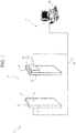
- Figure 1 is a schematic representation of a device 1 for detecting neutrons and gamma rays, comprising at least one detector 2 and an acquisition and data-analysis system 3, connected to the detector 2 for acquiring and processing signals received from the detector 2.
- the device 1 is used in a portal configuration, to provide a so-called radiation portal monitor 4 for detecting radionuclides possibly carried by persons and/or vehicles moving along assigned paths and specifically through the portal 4.
- the device 1 hence comprises a pair of facing detectors 2 connected to the acquisition and data-analysis system 3.
- the two detectors 2 are substantially the same and have the respective entry faces 5 facing one another (which in use face the object/source to be monitored).
- Each detector 2 may be constituted by one or more modular functional units 6, which can be combined together (set alongside one another horizontally and/or set on top of one another vertically) to provide portals 4 of different size and/or capacity.
- a detector 2 formed by a single functional unit 6.
- a detector 2 (i.e., a functional unit 6) extends substantially along a longitudinal axis A and comprises an active part 7 sensitive to gamma rays, which includes just one active material or else a number of active materials sensitive to gamma rays and uses only these active materials for detecting both gamma rays and neutrons.
- the active part 7 is formed by a plurality of scintillator layers 8 sensitive to gamma rays and absorber layers 9 set on top of one another and alternating with one another, having in particular the shape substantially of a thin sheet or plate, all of which are set parallel to one another and to a longitudinal plane (vertical in use) and are coupled to one another on respective substantially plane faces.
- the scintillator layers 8 are separated from one another by absorber layers 9.
- the scintillator layers 8 are plane layers made of a scintillator material sensitive to gamma rays, in particular an organic scintillator (also referred to as "plastic scintillator", i.e., made of polymeric material), for example, polyvinyltoluene.
- organic scintillator also referred to as "plastic scintillator”
- polymeric material for example, polyvinyltoluene.
- the absorber layers 9 are plane solid layers that contain at least one neutron-absorbing material, containing, for example, metal elements having a large section of impact for neutron capture.
- the neutron-absorbing material is able, by interacting with the incident neutrons, to produce in turn gamma rays.
- the absorber layers 9 contain cadmium or gadolinium in a solid form, in particular in metal form or in the form of oxides, etc., possibly applied to a sheet substrate.
- each absorber layer 9 is constituted by a sheet of polymeric material coated with gadolinium oxide, or containing gadolinium oxide in a resin-based matrix.
- the detector 2 comprises at least two scintillator layers 8 and preferably, but not necessarily, comprises a total number of scintillator layers 8 of between 5 and 15.
- the total amount of absorber material (gadolinium or cadmium, excluding the possible substrate material that forms, together with the absorber material, an absorber layer 9) set between two scintillator layers 8 is comprised between approximately 2 mg/cm 2 and approximately 2 g/cm 2 , irrespective of the deposition technology (coating, in the form of sheets, etc.) and the chemical form (metal, oxide, carbide, etc.).
- the scintillator layers 8 have transverse dimensions (width and length) of the order of tens of centimetres and a thickness of the order of the centimetre.
- the scintillator layers 8 have thickness comprised between approximately 5 and approximately 100 mm and, preferably, between approximately 5 mm and approximately 50 mm, in particular around approximately 20 mm.
- the absorber layers 9 have transverse dimensions similar to those of the scintillator layers 8 and a thickness such as not to induce significant energy losses by gamma rays with energies of the order of the megaelectronvolt, for example a thickness of some tens of microns.
- the scintillator layers 8 and the absorber layers 9 are arranged in elementary cells 10, each cell 10 being formed ( Figure 4 ) by a scintillator layer 8 and by an absorber layer 9 coupled along respective substantially plane faces.
- the active part 7 of the detector 2 is hence formed by a plurality of cells 10 set on top of one another, indicatively around ten cells, each formed by a scintillator layer 8 and by an absorber layer 9. It remains understood that the active part 7 may be formed with various arrangements of scintillator layers 8 and absorber layers 9.
- the active part 7 has a substantially prismatic shape, in particular the shape of a parallelepiped, which results from stacking of the scintillator layers 8 and of the absorber layers 9 (which have as a whole a rectangular shape in plan view), and extends along the axis A between two opposite longitudinal ends 11.
- the active part 7 is provided with photomultipliers 13 ( Figure 2 ), located at the ends 11 for detecting (or “reading") emission by the active part 7 or by parts thereof and in particular for collecting part of the energy released by interaction of the gamma rays with the scintillator material, as will be clarified hereinafter.
- the photomultipliers 13 are equipped with respective casings and magnetic shields (which are known).
- Optical coupling between the photomultipliers 13 and the active part 7 is provided by direct contact or else, as illustrated in Figure 2 , via light guides 14 that connect the photomultipliers 13 to the active part 7.
- the detector 2 comprises a plurality of active sections 15A, 15B, each of which is formed by a plurality of plane scintillator layers 8 and absorber layers 9 set on top of one another and alternating with one another.
- Each active section 15A, 15B has two or more scintillator layers 8 alternating with absorber layers 9.
- the detector 2 comprises a first active section 15A and a second active section 15B, which are set alongside one another and extend parallel to the axis A between the ends 11 and precisely between respective opposite longitudinal ends 11A, 11B of their own.
- Each active section 15A, 15B is formed by a plurality of plane scintillator layers 8 and absorber layers 9 set on top of one another and alternating with one another.
- Each active section 15A, 15B has two or more scintillator layers 8 alternating with absorber layers 9.
- the two active sections 15A, 15B are asymmetrical with respect to a longitudinal plane of the device, parallel to the axis A and to the scintillator layers 8 and the absorber layers 9; namely, the active sections 15A, 15B have a different thickness and/or a different number of scintillator layers 8 alternating with absorber layers 9 (i.e., of elementary cells 10) .
- the two active sections 15A, 15B are provided with respective photomultipliers 13A, 13B and are read independently of the respective photomultipliers 13A, 13B.
- each active section 15A, 15B is provided with a pair of photomultipliers 13A, 13B set at the longitudinal ends 11A, 11B of the respective active section 15A, 15B.
- Each active section 15A, 15B thus has two or more scintillator layers 8, alternating with absorber layers 9 and optically connected to a single pair of photomultipliers 13A, 13B, which are located at respective axially opposite longitudinal ends 11A, 11B of the active section 15A, 15B for collecting energy released by the interaction of the gamma rays with the scintillator material.
- Each pair of photomultipliers 13A, 13B is optically connected to a number of scintillator layers 8 alternating with absorber layers 9.
- Each end 11A, 11B has a peripheral end edge 16, substantially rectangular, and is connected to the respective photomultiplier 13A, 13B by an appropriately shaped light guide 14.
- each light guide 14 extends parallel to the axis A between an entry 17, which is joined to an edge 16 of an end 11A, 11B and has the shape of the edge 16 to which it is joined (hence, substantially rectangular), and an exit 18, which is opposite to the entry 17 and is joined to a photomultiplier 13 and has substantially the shape of an entry section of the photomultiplier 13 (or of the corresponding casing) to which it is joined (for example, a substantially circular shape).
- the photomultipliers 13 are provided with power-supply cables (not illustrated for simplicity) and transmission cables, which define a circuit 19 (schematically shown in Figure 1 ) that transmits the signals generated by the photomultipliers 13 to the acquisition and data-analysis system 3.
- the photomultipliers operate with a voltage comprised between 500 and 3000 V.
- the first active section 15A which in use is provided with the entry face 5 and faces the source or the object to be monitored (namely, in the portal configuration of the device 1, it faces the inside of the portal 4), has a smaller number of scintillator layers 8 and absorber layers 9 than the second active section 15B, which faces in use the side opposite to the source or object to be monitored (namely, the outside of the portal 5).
- the active section 15A hence also has a smaller thickness than the active section 15B and is provided with (i.e., is read by) photomultipliers 13A with a smaller diameter than the photomultipliers 13B associated to the active section 15B.
- Each photomultiplier 13 has a generically cylindrical shape and a diameter comparable with the overall thickness of the active section 7 to which it is connected.
- each photomultiplier 13 has a cross section of area at least 5% greater than the cross section of the active section 15 to which it is associated.
- the active section 15A is made up of two scintillator layers 8 and is read by 3-inch photomultipliers 13, while the second part is made up of ten scintillator layers 8 read by 5-inch photomultipliers.
- the active sections 15A, 15B may in any case have a different number of layers 8, 9.
- the two active sections 15A, 15B are separated by a separation plate 20 ( Figures 2 and 3 ), made, for example, of metal material, containing a greater amount of gadolinium than each of the absorber layers 9.
- the detector 2 (and hence the device 1 as a whole) presents a greater sensitivity in regard to low-energy photons, thanks to the independent reading of the first scintillator layers 8 (i.e., those of the first active section 15A, which are relatively few, for example one to five), where precisely the low-energy photons are absorbed.
- the active part 7 is advantageously contained within a casing 21, made, for example, of aluminium or plastic (illustrated, schematically, in Figure 1 ), having both functions of mechanical support and functions of shielding from light.
- the acquisition and data-analysis system 3 comprises at least one acquisition and data-analysis electronic board 23, connected to the photomultipliers 13, and a control unit 24 (for example, a computer), connected to the board 23.
- a control unit 24 for example, a computer
- the circuit 19 connects the photomultipliers 13 to the data-acquisition board 23 and the latter to the control unit 24.
- the board 23 operates as sampler/digitizer, preferably having a sampling rate not lower than 100 Msample/s.
- the board 23 is able to acquire, digitize, integrate in time, and save times and charges of analog signals of the duration of approximately 100 ns with rising edges of approximately 10 ns and a charge in the region of one picocoulomb, as well as to handle a high rate of events in pipeline, in the region of some hundreds of kilohertz per channel (non-processed data).
- the board 23 is configured so as to: detect in pipeline mode a signal coming from the detector 2, and precisely the presence of pulses having a voltage higher than a programmable threshold; digitize the signal received; and calculate the area of the signal received (which is proportional to the energy deposited in the scintillator material of the detector 2) and the time of arrival of the signal.
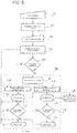
- the control unit 24 is provided with an acquisition and data-analysis program, which implements an algorithm for discrimination between gamma events and neutron events and operates, in implementation of the method for detecting neutrons and gamma rays emitted by radionuclides according to the invention, following the scheme appearing in Figure 6 and in particular so as to:
- the acquisition and data-analysis program includes the following steps:
- the signals of the photomultipliers 13 are acquired in pipeline mode by the board 23, which associates to each signal that exceeds the threshold value in voltage two values:
- the acquisition and data-analysis program processes said values of the signals and defines as event the condition in which there occurs a coincidence in time, within a window of the order of tens of nanoseconds, between two signals of the photomultipliers set at the two ends of the scintillator layers.
- Rejection of the component due to the measurement background is made during analysis of the data integrated over the entire measurement period, by subtracting the background energy spectrum from the total energy spectrum.
- the background component (which is assumed as being stable in the limits of uncertainty of measurement) is measured at the moment of installation and/or activation of the device 1.
- new periodic measurements of the background radiation may be carried out (for example, when the device 1 is not "busy” owing to passage of goods/persons to be screened) in order to update the measurement of the background radiation, and in this way the subtraction of the background component may be made "in real time", i.e., an instant after passage of the goods/person, immediately before supplying at output the energy spectrum.
- Discrimination between a gamma event and a neutron event is made in real time by implementation of the discrimination algorithm in the acquisition and data-analysis program.
- the program analyses, in real time, the total energies E TOT of the events.
- E LIM of the order of a few megaelectronvolts
- the total energy E TOT of the event is computed as sum of the energies E FRONT , E BACK released within the scintillator layers 8 of the active sections 15A, 15B.
- an event is classified as originating from a neutron source only in the presence of a non-zero signal in the rear active section 15B, set furthest away in use from the object/source to be monitored, i.e., if E TOT ⁇ E LIM and E BACK > 0.
- the program implements a further classification in some energy subintervals of amplitude of the order of hundreds of kiloelectronvolts, in such a way as to enable a basic identification of the source.
- typical gamma sources such as 137 Cs and 60 Co emit photons at different energies ( 137 Cs: approximately 600 keV; 60 Co: approximately 1.1 and approximately 1.3 MeV). Consequently, classifying the events in at least two distinct intervals containing these energy values makes it possible to identify the source and establish whether it is caesium or cobalt.
- the number of events is then integrated, in each energy window, over a time of the order of tenths of a second; in this way, the program computes an estimation of the corresponding rates of events.
- Threshold values on the rates of events are defined starting from the values of these rates in the absence of sources (i.e., in the presence of background radiation alone). In the case where one or more rates computed by the program exceed the threshold values, a corresponding alarm is issued.
- the gamma rays emitted by the radionuclides due to spontaneous decay interact in the detector 2 mainly as a result of the Compton effect and of photoelectric absorption, releasing a significant fraction of their energy into the active part 7.
- the spectrum of the incident gamma rays is determined, and, by applying appropriate cuts, the counting rates of the gamma rays in various energy windows are monitored. The increase of said counting rates with respect to the background level is indicative of the presence of a gamma radioactive source.
- the neutrons emitted by the radionuclides interact with the active part 7 of the detector 2.
- the neutrons lose almost all their kinetic energy (slowing-down or thermalization process) following upon elastic or anelastic impact mainly with the nuclei of the scintillator material.
- the neutrons are then captured by the nuclei of the absorber material with emission of a cascade of gamma rays having a characteristic total energy (for example, of approximately 8 MeV if gadolinium is used as absorber material), which interact as described previously.
- the signal of a neutron is detected and discriminated from the gamma-ray signal by setting of a threshold in the energy spectrum of gamma rays in the region of a few megaelectronvolts, since in a significant fraction of the gamma events due to neutron capture the total energy deposited is higher than that of gamma sources. Consequently, the increase, with respect to the background level, of the rate of the events with energy higher than this threshold is indicative of the presence of a neutron source.
- the program implements also the further classification in the energy subintervals for a basic identification of the source.
Landscapes
- Physics & Mathematics (AREA)
- Life Sciences & Earth Sciences (AREA)
- High Energy & Nuclear Physics (AREA)
- General Physics & Mathematics (AREA)
- Health & Medical Sciences (AREA)
- Molecular Biology (AREA)
- Spectroscopy & Molecular Physics (AREA)
- General Life Sciences & Earth Sciences (AREA)
- Geophysics (AREA)
- Measurement Of Radiation (AREA)
- Environmental & Geological Engineering (AREA)
- Geology (AREA)
Claims (17)
- Vorrichtung (1) zum Detektieren von Neuronen und Gammastrahlen, insbesondere von solchen, die von Radionukleotiden kommen, die von Personen und/oder Fahrzeugen getragen werden, die sich auf einem vorbestimmten Weg bewegen, umfassend mindestens einen Detektor (2) und ein Akquisitions- und Datenanalysesystem (3), verbunden mit dem Detektor (2); wobei der Detektor (2) nur einen aktiven Bestandteil (7) besitzt, der sich über eine longitudinale Achse (A) erstreckt und nur ein Material oder mehrere aktive Materialien beinhaltet, das gegenüber Gammastrahlen sensitiv ist, gebildet aus: einer Vielzahl von Szintillatorschichten (8), die gegenüber Gammastrahlen sensitiv sind, hergestellt aus einem Szintillatormaterial, das gegenüber Gammastrahlen sensitiv ist, insbesondere einem Plastikszintillator, zum Beispiel, Polyvinyltoluen; und angeordnet zwischen Absorberschichten (9), enthaltend mindestens ein Neutronen absorbierendes Material, insbesondere Cadmium oder Gadolinium; die Szintillatorschichten (8) im Wesentlichen aufweisend die Form einer dünnen Folie oder Platte, die miteinander gekoppelt sind auf den jeweiligen planaren Seiten; und wobei sowohl die Gammastrahlen als auch die Neutronen detektiert werden durch die gleichen Szintillatorschichten (8), die gegenüber Gammastrahlen sensitiv sind, und durch die Gammastrahlung, die erzeugt wird durch die Wechselwirkung der Neutronen mit dem Absorbermaterial der Absorberschichten (9); die Vorrichtung (1) gekennzeichnet dadurch, dass
der Detektor (2) organisiert ist in Abschnitte, wobei die Szintillatorschichten (8) und die Absorberschichten (9) in zwei oder mehr aktiven Abschnitten (15A, 15B) angeordnet sind, die gebildet sind jeweils aus Gruppen von Szintillatorschichten (8), die mit Absorberschichten (9) alternieren; wobei jeder aktive Abschnitt (15A, 15B) zwei oder mehr Szintillatorschichten (8) aufweist, die mit Absorberschichten (9) alternieren, und jeder Abschnitt jeweils optisch verbunden ist mit einem einzelnen Paar von Photovervielfachern (13A, 13B), angeordnet an den jeweiligen axial gegenüberstehenden longitudinalen Enden (11A, 11B) des aktiven Abschnitts (15A, 15B) zum Sammeln der Energie, die durch die Wechselwirkung der Gammastrahlen mit dem Szintillatormaterial freigesetzt wird, wobei jedes Paar von Photovervielfachern (13A, 13B) optisch verbunden ist mit einer Anzahl von Szintillatorschichten (8), die mit Absorberschichten (9) alternieren; und die aktiven Abschnitte (15A, 15B) unabhängig gelesen werden durch die jeweiligen Photovervielfacher (13A, 13B); und
dadurch, dass die Vorrichtung
mindestens einen ersten aktiven Abschnitt (15A) und einen zweiten aktiven Abschnitt (15B) umfasst, die zur einer longitudinalen Ebene asymmetrisch sind, parallel sind zu der Achse (A) und zu den Szintillatorschichten (8) und den Absorberschichten (9) der Vorrichtung; wobei die zwei aktiven Abschnitte (15A, 15B) eine unterschiedliche Dicke und/oder eine unterschiedliche Anzahl der Szintillatorschichten (8) aufweisen, die mit Absorberschichten (9) alternieren. - Vorrichtung gemäß Anspruch 1, wobei der erste aktive Abschnitt (15A), der im vorderen Abschnitt der Vorrichtung (1) und in Verwendung einem Objekt/einer Quelle gegenüberliegt, das beobachtet werden soll, eine Dicke und/oder Anzahl von Szintillatorschichten (8), die mit Absorberschichten (9) alternieren, aufweist, die kleiner ist als die des zweiten aktiven Abschnittes, der im hinteren Abschnitt der Vorrichtung (1) angeordnet ist, und in Verwendung der Seite gegenüberliegt, die von dem Objekt/der Quelle abgewandt ist.
- Vorrichtung gemäß einem der vorstehenden Ansprüche, wobei das Szintillatormaterial ein Plastikszintillator ist, insbesondere Polyvinyltoluen; und das Neutronen absorbierende Material Cadmium oder Gadolinium ist.
- Vorrichtung gemäß einem der vorstehenden Ansprüche, wobei jede Absorberschicht (9), die zwei Szintillatorschichten (8) trennt, eine Gesamtmenge an Absorbermaterial zwischen ungefähr 2 mg/cm2 und ungefähr 2 g/cm2 umfasst.
- Vorrichtung gemäß einem der vorstehenden Ansprüche, wobei die optische Verbindung zwischen den Photovervielfachern (13) und den jeweiligen aktiven Abschnitten (15A, 15B) entweder durch direkten Kontakt oder über Lichtleiter (14) erhalten wird, die die Photovervielfacher (13) mit den aktiven Abschnitten (15A, 15B) verbinden.
- Vorrichtung gemäß einem der vorstehenden Ansprüche, wobei die Photovervielfacher (13) mit den jeweiligen aktiven Abschnitten (15A, 15B) jeweils durch Lichtleiter (14) verbunden sind; jeder Lichtleiter (14) einen Eingang (17) besitzt, der mit einer Kante (16) eines Endes (11) des jeweiligen aktiven Abschnittes (15A, 15B) und die Form der Kante (16) im Wesentlichen rechteckig ist; und einen Ausgang (18), gegenüber dem Eingang (17), aufweist, und der verbunden ist mit einem Photovervielfacher (13) und der im Wesentlichen die Form des Eingangsabschnitts aufweist, mit dem er verbunden ist.
- Vorrichtung gemäß einem der vorstehenden Ansprüche, wobei die zwei aktiven Abschnitte (15A, 15B) durch eine Platte (20) getrennt werden, die eine größere Mengen an Absorbermaterial enthält als jede der Absorberschichten (9).
- Vorrichtung gemäß einem der vorstehenden Ansprüche, wobei die Vorrichtung (1) eine Portalkonfiguration besitzt und eine Portal (5) darstellt zum Beobachten der Strahlung zum Detektieren von Radionukleotiden kommen, die von Personen und/oder Fahrzeugen getragen werden, die sich durch das Portal (5) bewegen; die Vorrichtung (1) ein Paar von sich gegenüberstehenden Detektoren (2) umfasst, die mit dem Akquisitions- und Datenanalysesystem (3) verbunden sind.
- Vorrichtung gemäß Anspruch 8, wobei jeder Detektor (2) aus einem oder mehreren modularen funktionalen Einheiten (6) besteht, die miteinander kombiniert werden können und aufeinander horizontal ausgerichtet sind und/oder vertikal aufeinander ausgerichtet sind, um Portale (5) von verschiedener Größe und/oder Kapazität bereitzustellen.
- Vorrichtung gemäß einem der vorstehenden Ansprüche, wobei das Akquisitions- und Datenanalysesystem (3) konfiguriert ist: die Signale zu analysieren, die von dem Detektor (2) kommen und die Gesamtenergie zu berechnen, die innerhalb des Detektors (2) infolge der Interaktion mit Gammastrahlen oder Neutronen freigesetzt wird; und zwischen auf den Detektor (2) eintreffenden Gammastrahlen und Neutronen zu unterscheiden in Abhängigkeit davon, ob die Energie höher oder niedriger ist als eine vordefinierte Schwelle.
- Vorrichtung gemäß Anspruch 10, wobei das Akquisitions- und Datenanalysesystem (3) konfiguriert ist, die Gesamtenergie ETOT eines Ereignisses zu berechnen, die innerhalb der Szintillatorschichten (8) freigesetzt wird, und die Gesamtenergie ETOT mit einem vordefinierten Grenzwert ELIM zu vergleichen; und das Ereignis zu klassifizieren als:• Ein von einer Gammaquelle stammendes Ereignis, wenn ETOT < ELIM• Ein von einer Neutronenquelle stammendes Ereignis, wenn ETOT ≥ ELIM.
- Vorrichtung gemäß Anspruch 11, wobei das Akquisitions- und Datenanalysesystem (3) konfiguriert ist: die Gesamtenergie ETOT eines Ereignisses als die Summe der Energien EFRONT, EBACK zu berechnen, die innerhalb der Szintillatorschichten (8) des ersten aktiven Abschnitts (15A) und des zweiten Abschnitts (15B) jeweils freigesetzt werden, und das Ereignis als ausschließlich einer Neutronenquelle stammend zu klassifizieren beim Vorliegen eines von Null verschiedenen Signals in dem aktiven Abschnitt (15B), der bei Verwendung von dem Objekt/der Quelle am weitesten entfernt ist, d.h. wenn ETOT ≥ ELIM und EBACK > 0.
- Vorrichtung gemäß Anspruch 11 oder Anspruch 12, wobei das Akquisitions- und Datenanalysesystem (3) konfiguriert ist, das Ereignis, für den Fall von Ereignissen, die als von einer Gammaquelle stammend klassifiziert werden, in Energiesubintervallen zur Basisidentifikation der Quelle zu klassifizieren.
- Verfahren zum Detektieren von Neuronen und Gammastrahlen umfassend die Schritte:- Bereitstellen einer Vorrichtung (1) gemäß einem der vorstehenden Ansprüche;- Analysieren der Signale, die von dem Detektor (2) kommen und Berechnen der Gesamtenergie, die innerhalb des Detektors (2) infolge der Interaktion mit Gammastrahlen oder Neutronen freigesetzt wird; und- Unterscheiden zwischen auf den Detektor (2) eintreffenden Gammastrahlen und Neutronen in Abhängigkeit davon, ob die Energie höher oder niedriger ist als eine vordefinierte Schwelle.
- Verfahren gemäß Anspruch 14, umfassend die Schritte: Berechnen der Gesamtenergie ETOT eines Ereignisses, die innerhalb der Szintillatorschichten (8) freigesetzt wird, und Vergleichen der Gesamtenergie ETOT mit einem vordefinierten Grenzwert ELIM; und Klassifizieren des Ereignisses als:• Ein von einer Gammaquelle stammendes Ereignis, wenn ETOT < ELIM• Ein von einer Neutronenquelle stammendes Ereignis, wenn ETOT ≥ ELIM.
- Verfahren gemäß Anspruch 15, wobei: die Gesamtenergie ETOT eines Ereignisses als die Summe der Energien EFRONT, EBACK berechnet wird, die innerhalb der Szintillatorschichten (8) des ersten aktiven Abschnitts (15A) und des zweiten Abschnitts (15B) jeweils freigesetzt werden, und das Ereignis als ausschließlich einer Neutronenquelle stammend klassifizieren wird beim Vorliegen eines von Null verschiedenen Signals in dem aktiven Abschnitt (15B), der bei Verwendung von dem Objekt/der Quelle am weitesten entfernt ist, d.h. wenn ETOT ≥ ELIM und EBACK > 0.
- Verfahren gemäß Anspruch 15 oder Anspruch 16, umfassend die Schritte, Klassifizieren des Ereignisses, für den Fall von Ereignissen, die als von einer Gammaquelle stammend klassifiziert werden, in Energiesubintervallen zur Basisidentifikation der Quelle.
Applications Claiming Priority (2)
| Application Number | Priority Date | Filing Date | Title |
|---|---|---|---|
| IT001862A ITMI20131862A1 (it) | 2013-11-08 | 2013-11-08 | Dispositivo e metodo per la rivelazione di neutroni e raggi gamma |
| PCT/IB2014/065876 WO2015068133A1 (en) | 2013-11-08 | 2014-11-07 | Device and method for detecting neutrons and gamma rays |
Publications (3)
| Publication Number | Publication Date |
|---|---|
| EP3066496A1 EP3066496A1 (de) | 2016-09-14 |
| EP3066496B1 true EP3066496B1 (de) | 2019-04-03 |
| EP3066496B8 EP3066496B8 (de) | 2019-06-05 |
Family
ID=50073285
Family Applications (1)
| Application Number | Title | Priority Date | Filing Date |
|---|---|---|---|
| EP14828278.3A Active EP3066496B8 (de) | 2013-11-08 | 2014-11-07 | Vorrichtung und verfahren zur detektion von neutronen und gamma-strahlung |
Country Status (4)
| Country | Link |
|---|---|
| US (1) | US10107934B2 (de) |
| EP (1) | EP3066496B8 (de) |
| IT (1) | ITMI20131862A1 (de) |
| WO (1) | WO2015068133A1 (de) |
Families Citing this family (13)
| Publication number | Priority date | Publication date | Assignee | Title |
|---|---|---|---|---|
| US9804290B2 (en) * | 2013-04-02 | 2017-10-31 | Morpho Detection, Llc | Cross-correlated gamma ray and neutron detector |
| CN106324658B (zh) * | 2015-06-30 | 2019-04-23 | 中国辐射防护研究院 | 掺杂中子灵敏物质镉的塑料闪烁体及其测量热中子的方法 |
| JP6742259B2 (ja) * | 2017-03-02 | 2020-08-19 | 住友重機械工業株式会社 | 中性子線検出システム、及び中性子線検出システムの設定方法 |
| EP3797057A4 (de) | 2018-05-21 | 2022-02-23 | Rombakh, Volodymyr Pavlovich | Nichtinvasive überwachung von atomaren reaktionen zur erkennung struktureller ausfälle |
| CN112997102B (zh) * | 2018-06-25 | 2024-09-10 | Kth控股公司 | 辐射检测系统和方法 |
| CN109061708A (zh) * | 2018-09-13 | 2018-12-21 | 公安部第研究所 | 一种门式放射性监测与识别系统 |
| IT201900000076A1 (it) * | 2019-01-04 | 2020-07-04 | Univ Degli Studi Padova | Dispositivo e un procedimento per la misura del contenuto idrico del suolo, della vegetazione e del manto nevoso |
| FR3104738B1 (fr) | 2019-12-13 | 2021-12-17 | Commissariat Energie Atomique | Procédé de détection de radiations et système associé mettant en œuvre une discrimination des coincidences neutron-gamma |
| EP4115215B8 (de) * | 2020-03-05 | 2025-12-17 | Rapiscan Holdings, Inc. | Verfahren zur bestimmung eines neutronenflusses mittels eines tragbaren radionuklididentifizierungsgerätes (rid), einen szintillationswerkstoff mit iod enthaltend |
| CN111856603B (zh) * | 2020-07-23 | 2023-06-30 | 北京永新医疗设备有限公司 | 闸机设备及其控制方法 |
| US10941274B1 (en) * | 2020-09-01 | 2021-03-09 | King Abdulaziz University | Nanoparticle-infused ABS filament for 3D-printed materials and uses for neutron detection and discrimination |
| US12130393B2 (en) * | 2022-09-30 | 2024-10-29 | United States Of America As Represented By The Secretary Of The Navy | Layered scintillating neutron detector |
| US20250216563A1 (en) * | 2023-12-28 | 2025-07-03 | Applied Research, LLC | Method and System for Fast Radiation Signature Generation and Accurate Mixture Identification |
Family Cites Families (4)
| Publication number | Priority date | Publication date | Assignee | Title |
|---|---|---|---|---|
| US20110101230A1 (en) * | 2005-02-04 | 2011-05-05 | Dan Inbar | Advanced SNM Detector |
| US8723126B2 (en) * | 2009-05-26 | 2014-05-13 | The United States Of America, As Represented By The Secretary Of The Navy | Scintillator material |
| GB2490513B (en) * | 2011-05-04 | 2015-11-04 | Symetrica Ltd | Neutron spectrometer |
| CN104169741A (zh) | 2012-02-04 | 2014-11-26 | 拉皮斯坎系统股份有限公司 | 复合伽马中子检测系统 |
-
2013
- 2013-11-08 IT IT001862A patent/ITMI20131862A1/it unknown
-
2014
- 2014-11-07 WO PCT/IB2014/065876 patent/WO2015068133A1/en not_active Ceased
- 2014-11-07 US US15/034,921 patent/US10107934B2/en active Active
- 2014-11-07 EP EP14828278.3A patent/EP3066496B8/de active Active
Non-Patent Citations (1)
| Title |
|---|
| None * |
Also Published As
| Publication number | Publication date |
|---|---|
| EP3066496B8 (de) | 2019-06-05 |
| ITMI20131862A1 (it) | 2015-05-09 |
| US10107934B2 (en) | 2018-10-23 |
| EP3066496A1 (de) | 2016-09-14 |
| WO2015068133A1 (en) | 2015-05-14 |
| US20160291196A1 (en) | 2016-10-06 |
Similar Documents
| Publication | Publication Date | Title |
|---|---|---|
| EP3066496B1 (de) | Vorrichtung und verfahren zur detektion von neutronen und gamma-strahlung | |
| US8436315B1 (en) | Compact thermal neutron monitor | |
| US7388206B2 (en) | Pulse shape discrimination method and apparatus for high-sensitivity radioisotope identification with an integrated neutron-gamma radiation detector | |
| EP2778716B1 (de) | Detektor und verfahren zum gleichzeitigen nachweis von gamma- und neutronenstrahlen damit | |
| US8294114B2 (en) | Method for monitoring an unknown container or the contents in a volume, monitoring system for being used with said method, and radiation detector for such a monitoring system | |
| US20120074326A1 (en) | Apparatus and method for neutron detection with neutron-absorbing calorimetric gamma detectors | |
| EP2290406B1 (de) | Vorrichtung und Verfahren zur Neutronendetektion mit neutronenabsorbierenden kalorimetrischen Gamma-Detektoren | |
| US20070069146A1 (en) | Fiber optic thermal/fast neutron and gamma ray scintillation detector | |
| US20120080599A1 (en) | Apparatus and method for neutron detection by capture-gamma calorimetry | |
| CA2528177A1 (en) | Neutron and gamma ray monitor | |
| EP3811121B1 (de) | Strahlungsdetektionssystem und -verfahren | |
| EP1989573B1 (de) | Festkörperneutrondetektor | |
| EP3401706B1 (de) | Verfahren zur detektion von neutronen mit szintillationsdetektoren zur gamma-spektroskopie | |
| RU2189057C2 (ru) | Сцинтилляционный детектор нейтронного и гамма-излучения | |
| US20230400597A1 (en) | Neutron counting by delayed capture-gamma detection (dcd) | |
| Kandlakunta | Gamma Rays Rejection in a Gadolinium based Semiconductor Neutron Detector | |
| US20080205580A1 (en) | Real-time multiplicity counter | |
| RU2272301C1 (ru) | Сцинтилляционный детектор нейтронов | |
| Trombetta et al. | Investigation of the use of coincidences between fast neutrons and gamma rays for the detection of special nuclear materials | |
| EP3444639A1 (de) | Schneller neutronendetektor basierend auf protonenrückstossdetektion in einem zusammengesetzten szintillator mit eingebetteten wellenlängenverschiebungsfasern | |
| RU2615709C1 (ru) | Устройство для измерения плотности потока нейтронов ядерной энергетической установки в условиях фоновой помехи от гамма-квантов и высокоэнергетичных космических электронов и протонов | |
| Trombetta et al. | Sensitive detection of special nuclear materials for rpm applications based on gamma-fast neutron coincidence counting | |
| Farsoni et al. | Design and modeling of a Compton-suppressed phoswich detector for radioxenon monitoring | |
| Farsoni et al. | Characterization of triple-layer phoswich detector for radioxenon measurements | |
| RU2413246C1 (ru) | Твердотельный детектор нейтронов |
Legal Events
| Date | Code | Title | Description |
|---|---|---|---|
| PUAI | Public reference made under article 153(3) epc to a published international application that has entered the european phase |
Free format text: ORIGINAL CODE: 0009012 |
|
| 17P | Request for examination filed |
Effective date: 20160523 |
|
| AK | Designated contracting states |
Kind code of ref document: A1 Designated state(s): AL AT BE BG CH CY CZ DE DK EE ES FI FR GB GR HR HU IE IS IT LI LT LU LV MC MK MT NL NO PL PT RO RS SE SI SK SM TR |
|
| AX | Request for extension of the european patent |
Extension state: BA ME |
|
| DAX | Request for extension of the european patent (deleted) | ||
| GRAP | Despatch of communication of intention to grant a patent |
Free format text: ORIGINAL CODE: EPIDOSNIGR1 |
|
| STAA | Information on the status of an ep patent application or granted ep patent |
Free format text: STATUS: GRANT OF PATENT IS INTENDED |
|
| INTG | Intention to grant announced |
Effective date: 20180910 |
|
| GRAJ | Information related to disapproval of communication of intention to grant by the applicant or resumption of examination proceedings by the epo deleted |
Free format text: ORIGINAL CODE: EPIDOSDIGR1 |
|
| STAA | Information on the status of an ep patent application or granted ep patent |
Free format text: STATUS: REQUEST FOR EXAMINATION WAS MADE |
|
| INTC | Intention to grant announced (deleted) | ||
| GRAR | Information related to intention to grant a patent recorded |
Free format text: ORIGINAL CODE: EPIDOSNIGR71 |
|
| GRAS | Grant fee paid |
Free format text: ORIGINAL CODE: EPIDOSNIGR3 |
|
| STAA | Information on the status of an ep patent application or granted ep patent |
Free format text: STATUS: GRANT OF PATENT IS INTENDED |
|
| GRAA | (expected) grant |
Free format text: ORIGINAL CODE: 0009210 |
|
| STAA | Information on the status of an ep patent application or granted ep patent |
Free format text: STATUS: THE PATENT HAS BEEN GRANTED |
|
| GRAT | Correction requested after decision to grant or after decision to maintain patent in amended form |
Free format text: ORIGINAL CODE: EPIDOSNCDEC |
|
| REG | Reference to a national code |
Ref country code: DE Ref legal event code: R081 Ref document number: 602014044141 Country of ref document: DE Owner name: ISTITUTO NAZIONALE DI FISICA NUCLEARE, IT Free format text: FORMER OWNERS: ANSALDO NUCLEARE S.P.A., GENOVA, IT; INSTITUTO NAZIONALE DI FISICA NUCLEARE, FRASCATI, IT Ref country code: DE Ref legal event code: R081 Ref document number: 602014044141 Country of ref document: DE Owner name: ANSALDO NUCLEARE S.P.A., IT Free format text: FORMER OWNERS: ANSALDO NUCLEARE S.P.A., GENOVA, IT; INSTITUTO NAZIONALE DI FISICA NUCLEARE, FRASCATI, IT |
|
| AK | Designated contracting states |
Kind code of ref document: B1 Designated state(s): AL AT BE BG CH CY CZ DE DK EE ES FI FR GB GR HR HU IE IS IT LI LT LU LV MC MK MT NL NO PL PT RO RS SE SI SK SM TR |
|
| INTG | Intention to grant announced |
Effective date: 20190226 |
|
| REG | Reference to a national code |
Ref country code: GB Ref legal event code: FG4D |
|
| REG | Reference to a national code |
Ref country code: CH Ref legal event code: EP Ref country code: AT Ref legal event code: REF Ref document number: 1116421 Country of ref document: AT Kind code of ref document: T Effective date: 20190415 |
|
| RAP2 | Party data changed (patent owner data changed or rights of a patent transferred) |
Owner name: ANSALDO NUCLEARE S.P.A. Owner name: ISTITUTO NAZIONALE DI FISICA NUCLEARE |
|
| REG | Reference to a national code |
Ref country code: DE Ref legal event code: R096 Ref document number: 602014044141 Country of ref document: DE |
|
| REG | Reference to a national code |
Ref country code: IE Ref legal event code: FG4D |
|
| REG | Reference to a national code |
Ref country code: CH Ref legal event code: PK Free format text: BERICHTIGUNG B8 |
|
| REG | Reference to a national code |
Ref country code: CH Ref legal event code: NV Representative=s name: MOINAS AND SAVOYE SARL, CH |
|
| REG | Reference to a national code |
Ref country code: NL Ref legal event code: MP Effective date: 20190403 |
|
| REG | Reference to a national code |
Ref country code: LT Ref legal event code: MG4D |
|
| REG | Reference to a national code |
Ref country code: AT Ref legal event code: MK05 Ref document number: 1116421 Country of ref document: AT Kind code of ref document: T Effective date: 20190403 |
|
| PG25 | Lapsed in a contracting state [announced via postgrant information from national office to epo] |
Ref country code: NL Free format text: LAPSE BECAUSE OF FAILURE TO SUBMIT A TRANSLATION OF THE DESCRIPTION OR TO PAY THE FEE WITHIN THE PRESCRIBED TIME-LIMIT Effective date: 20190403 |
|
| PG25 | Lapsed in a contracting state [announced via postgrant information from national office to epo] |
Ref country code: SE Free format text: LAPSE BECAUSE OF FAILURE TO SUBMIT A TRANSLATION OF THE DESCRIPTION OR TO PAY THE FEE WITHIN THE PRESCRIBED TIME-LIMIT Effective date: 20190403 Ref country code: HR Free format text: LAPSE BECAUSE OF FAILURE TO SUBMIT A TRANSLATION OF THE DESCRIPTION OR TO PAY THE FEE WITHIN THE PRESCRIBED TIME-LIMIT Effective date: 20190403 Ref country code: PT Free format text: LAPSE BECAUSE OF FAILURE TO SUBMIT A TRANSLATION OF THE DESCRIPTION OR TO PAY THE FEE WITHIN THE PRESCRIBED TIME-LIMIT Effective date: 20190803 Ref country code: NO Free format text: LAPSE BECAUSE OF FAILURE TO SUBMIT A TRANSLATION OF THE DESCRIPTION OR TO PAY THE FEE WITHIN THE PRESCRIBED TIME-LIMIT Effective date: 20190703 Ref country code: FI Free format text: LAPSE BECAUSE OF FAILURE TO SUBMIT A TRANSLATION OF THE DESCRIPTION OR TO PAY THE FEE WITHIN THE PRESCRIBED TIME-LIMIT Effective date: 20190403 Ref country code: AL Free format text: LAPSE BECAUSE OF FAILURE TO SUBMIT A TRANSLATION OF THE DESCRIPTION OR TO PAY THE FEE WITHIN THE PRESCRIBED TIME-LIMIT Effective date: 20190403 Ref country code: CZ Free format text: LAPSE BECAUSE OF FAILURE TO SUBMIT A TRANSLATION OF THE DESCRIPTION OR TO PAY THE FEE WITHIN THE PRESCRIBED TIME-LIMIT Effective date: 20190403 Ref country code: ES Free format text: LAPSE BECAUSE OF FAILURE TO SUBMIT A TRANSLATION OF THE DESCRIPTION OR TO PAY THE FEE WITHIN THE PRESCRIBED TIME-LIMIT Effective date: 20190403 Ref country code: LT Free format text: LAPSE BECAUSE OF FAILURE TO SUBMIT A TRANSLATION OF THE DESCRIPTION OR TO PAY THE FEE WITHIN THE PRESCRIBED TIME-LIMIT Effective date: 20190403 |
|
| PG25 | Lapsed in a contracting state [announced via postgrant information from national office to epo] |
Ref country code: BG Free format text: LAPSE BECAUSE OF FAILURE TO SUBMIT A TRANSLATION OF THE DESCRIPTION OR TO PAY THE FEE WITHIN THE PRESCRIBED TIME-LIMIT Effective date: 20190703 Ref country code: RS Free format text: LAPSE BECAUSE OF FAILURE TO SUBMIT A TRANSLATION OF THE DESCRIPTION OR TO PAY THE FEE WITHIN THE PRESCRIBED TIME-LIMIT Effective date: 20190403 Ref country code: PL Free format text: LAPSE BECAUSE OF FAILURE TO SUBMIT A TRANSLATION OF THE DESCRIPTION OR TO PAY THE FEE WITHIN THE PRESCRIBED TIME-LIMIT Effective date: 20190403 Ref country code: LV Free format text: LAPSE BECAUSE OF FAILURE TO SUBMIT A TRANSLATION OF THE DESCRIPTION OR TO PAY THE FEE WITHIN THE PRESCRIBED TIME-LIMIT Effective date: 20190403 Ref country code: GR Free format text: LAPSE BECAUSE OF FAILURE TO SUBMIT A TRANSLATION OF THE DESCRIPTION OR TO PAY THE FEE WITHIN THE PRESCRIBED TIME-LIMIT Effective date: 20190704 |
|
| PG25 | Lapsed in a contracting state [announced via postgrant information from national office to epo] |
Ref country code: AT Free format text: LAPSE BECAUSE OF FAILURE TO SUBMIT A TRANSLATION OF THE DESCRIPTION OR TO PAY THE FEE WITHIN THE PRESCRIBED TIME-LIMIT Effective date: 20190403 Ref country code: IS Free format text: LAPSE BECAUSE OF FAILURE TO SUBMIT A TRANSLATION OF THE DESCRIPTION OR TO PAY THE FEE WITHIN THE PRESCRIBED TIME-LIMIT Effective date: 20190803 |
|
| REG | Reference to a national code |
Ref country code: DE Ref legal event code: R097 Ref document number: 602014044141 Country of ref document: DE |
|
| PG25 | Lapsed in a contracting state [announced via postgrant information from national office to epo] |
Ref country code: EE Free format text: LAPSE BECAUSE OF FAILURE TO SUBMIT A TRANSLATION OF THE DESCRIPTION OR TO PAY THE FEE WITHIN THE PRESCRIBED TIME-LIMIT Effective date: 20190403 Ref country code: DK Free format text: LAPSE BECAUSE OF FAILURE TO SUBMIT A TRANSLATION OF THE DESCRIPTION OR TO PAY THE FEE WITHIN THE PRESCRIBED TIME-LIMIT Effective date: 20190403 Ref country code: RO Free format text: LAPSE BECAUSE OF FAILURE TO SUBMIT A TRANSLATION OF THE DESCRIPTION OR TO PAY THE FEE WITHIN THE PRESCRIBED TIME-LIMIT Effective date: 20190403 Ref country code: SK Free format text: LAPSE BECAUSE OF FAILURE TO SUBMIT A TRANSLATION OF THE DESCRIPTION OR TO PAY THE FEE WITHIN THE PRESCRIBED TIME-LIMIT Effective date: 20190403 |
|
| PLBE | No opposition filed within time limit |
Free format text: ORIGINAL CODE: 0009261 |
|
| STAA | Information on the status of an ep patent application or granted ep patent |
Free format text: STATUS: NO OPPOSITION FILED WITHIN TIME LIMIT |
|
| PG25 | Lapsed in a contracting state [announced via postgrant information from national office to epo] |
Ref country code: SM Free format text: LAPSE BECAUSE OF FAILURE TO SUBMIT A TRANSLATION OF THE DESCRIPTION OR TO PAY THE FEE WITHIN THE PRESCRIBED TIME-LIMIT Effective date: 20190403 |
|
| 26N | No opposition filed |
Effective date: 20200106 |
|
| PG25 | Lapsed in a contracting state [announced via postgrant information from national office to epo] |
Ref country code: TR Free format text: LAPSE BECAUSE OF FAILURE TO SUBMIT A TRANSLATION OF THE DESCRIPTION OR TO PAY THE FEE WITHIN THE PRESCRIBED TIME-LIMIT Effective date: 20190403 |
|
| PG25 | Lapsed in a contracting state [announced via postgrant information from national office to epo] |
Ref country code: SI Free format text: LAPSE BECAUSE OF FAILURE TO SUBMIT A TRANSLATION OF THE DESCRIPTION OR TO PAY THE FEE WITHIN THE PRESCRIBED TIME-LIMIT Effective date: 20190403 |
|
| PG25 | Lapsed in a contracting state [announced via postgrant information from national office to epo] |
Ref country code: MC Free format text: LAPSE BECAUSE OF FAILURE TO SUBMIT A TRANSLATION OF THE DESCRIPTION OR TO PAY THE FEE WITHIN THE PRESCRIBED TIME-LIMIT Effective date: 20190403 Ref country code: LU Free format text: LAPSE BECAUSE OF NON-PAYMENT OF DUE FEES Effective date: 20191107 |
|
| PG25 | Lapsed in a contracting state [announced via postgrant information from national office to epo] |
Ref country code: CY Free format text: LAPSE BECAUSE OF FAILURE TO SUBMIT A TRANSLATION OF THE DESCRIPTION OR TO PAY THE FEE WITHIN THE PRESCRIBED TIME-LIMIT Effective date: 20190403 |
|
| PG25 | Lapsed in a contracting state [announced via postgrant information from national office to epo] |
Ref country code: MT Free format text: LAPSE BECAUSE OF FAILURE TO SUBMIT A TRANSLATION OF THE DESCRIPTION OR TO PAY THE FEE WITHIN THE PRESCRIBED TIME-LIMIT Effective date: 20190403 Ref country code: HU Free format text: LAPSE BECAUSE OF FAILURE TO SUBMIT A TRANSLATION OF THE DESCRIPTION OR TO PAY THE FEE WITHIN THE PRESCRIBED TIME-LIMIT; INVALID AB INITIO Effective date: 20141107 |
|
| PG25 | Lapsed in a contracting state [announced via postgrant information from national office to epo] |
Ref country code: MK Free format text: LAPSE BECAUSE OF FAILURE TO SUBMIT A TRANSLATION OF THE DESCRIPTION OR TO PAY THE FEE WITHIN THE PRESCRIBED TIME-LIMIT Effective date: 20190403 |
|
| PGFP | Annual fee paid to national office [announced via postgrant information from national office to epo] |
Ref country code: IT Payment date: 20221102 Year of fee payment: 9 Ref country code: IE Payment date: 20221118 Year of fee payment: 9 Ref country code: GB Payment date: 20221122 Year of fee payment: 9 Ref country code: FR Payment date: 20221122 Year of fee payment: 9 Ref country code: DE Payment date: 20221128 Year of fee payment: 9 |
|
| PGFP | Annual fee paid to national office [announced via postgrant information from national office to epo] |
Ref country code: CH Payment date: 20221123 Year of fee payment: 9 Ref country code: BE Payment date: 20221124 Year of fee payment: 9 |
|
| REG | Reference to a national code |
Ref country code: DE Ref legal event code: R119 Ref document number: 602014044141 Country of ref document: DE |
|
| REG | Reference to a national code |
Ref country code: CH Ref legal event code: PL |
|
| PG25 | Lapsed in a contracting state [announced via postgrant information from national office to epo] |
Ref country code: CH Free format text: LAPSE BECAUSE OF NON-PAYMENT OF DUE FEES Effective date: 20231130 |
|
| GBPC | Gb: european patent ceased through non-payment of renewal fee |
Effective date: 20231107 |
|
| PG25 | Lapsed in a contracting state [announced via postgrant information from national office to epo] |
Ref country code: CH Free format text: LAPSE BECAUSE OF NON-PAYMENT OF DUE FEES Effective date: 20231130 |
|
| REG | Reference to a national code |
Ref country code: BE Ref legal event code: MM Effective date: 20231130 |
|
| REG | Reference to a national code |
Ref country code: IE Ref legal event code: MM4A |
|
| PG25 | Lapsed in a contracting state [announced via postgrant information from national office to epo] |
Ref country code: DE Free format text: LAPSE BECAUSE OF NON-PAYMENT OF DUE FEES Effective date: 20240601 Ref country code: IE Free format text: LAPSE BECAUSE OF NON-PAYMENT OF DUE FEES Effective date: 20231107 |
|
| PG25 | Lapsed in a contracting state [announced via postgrant information from national office to epo] |
Ref country code: GB Free format text: LAPSE BECAUSE OF NON-PAYMENT OF DUE FEES Effective date: 20231107 |
|
| PG25 | Lapsed in a contracting state [announced via postgrant information from national office to epo] |
Ref country code: BE Free format text: LAPSE BECAUSE OF NON-PAYMENT OF DUE FEES Effective date: 20231130 |
|
| PG25 | Lapsed in a contracting state [announced via postgrant information from national office to epo] |
Ref country code: FR Free format text: LAPSE BECAUSE OF NON-PAYMENT OF DUE FEES Effective date: 20231130 |
|
| PG25 | Lapsed in a contracting state [announced via postgrant information from national office to epo] |
Ref country code: IE Free format text: LAPSE BECAUSE OF NON-PAYMENT OF DUE FEES Effective date: 20231107 Ref country code: GB Free format text: LAPSE BECAUSE OF NON-PAYMENT OF DUE FEES Effective date: 20231107 Ref country code: FR Free format text: LAPSE BECAUSE OF NON-PAYMENT OF DUE FEES Effective date: 20231130 Ref country code: DE Free format text: LAPSE BECAUSE OF NON-PAYMENT OF DUE FEES Effective date: 20240601 Ref country code: BE Free format text: LAPSE BECAUSE OF NON-PAYMENT OF DUE FEES Effective date: 20231130 |
|
| PG25 | Lapsed in a contracting state [announced via postgrant information from national office to epo] |
Ref country code: IT Free format text: LAPSE BECAUSE OF NON-PAYMENT OF DUE FEES Effective date: 20231107 |
|
| PG25 | Lapsed in a contracting state [announced via postgrant information from national office to epo] |
Ref country code: IT Free format text: LAPSE BECAUSE OF NON-PAYMENT OF DUE FEES Effective date: 20231107 |